CN1090423A - The disc box - Google Patents
The disc box Download PDFInfo
- Publication number
- CN1090423A CN1090423A CN93120558A CN93120558A CN1090423A CN 1090423 A CN1090423 A CN 1090423A CN 93120558 A CN93120558 A CN 93120558A CN 93120558 A CN93120558 A CN 93120558A CN 1090423 A CN1090423 A CN 1090423A
- Authority
- CN
- China
- Prior art keywords
- pallet
- disc
- mentioned
- shell
- combination member
- Prior art date
- Legal status (The legal status is an assumption and is not a legal conclusion. Google has not performed a legal analysis and makes no representation as to the accuracy of the status listed.)
- Pending
Links
- 238000003780 insertion Methods 0.000 claims abstract description 30
- 230000037431 insertion Effects 0.000 claims abstract description 30
- 239000000284 extract Substances 0.000 claims abstract description 10
- 238000000605 extraction Methods 0.000 claims description 20
- 238000003825 pressing Methods 0.000 claims description 14
- 238000003860 storage Methods 0.000 claims description 12
- RKTYLMNFRDHKIL-UHFFFAOYSA-N copper;5,10,15,20-tetraphenylporphyrin-22,24-diide Chemical group [Cu+2].C1=CC(C(=C2C=CC([N-]2)=C(C=2C=CC=CC=2)C=2C=CC(N=2)=C(C=2C=CC=CC=2)C2=CC=C3[N-]2)C=2C=CC=CC=2)=NC1=C3C1=CC=CC=C1 RKTYLMNFRDHKIL-UHFFFAOYSA-N 0.000 claims description 2
- 230000003321 amplification Effects 0.000 description 4
- 238000003199 nucleic acid amplification method Methods 0.000 description 4
- 230000001172 regenerating effect Effects 0.000 description 4
- 230000015572 biosynthetic process Effects 0.000 description 3
- 238000006073 displacement reaction Methods 0.000 description 3
- 238000012856 packing Methods 0.000 description 3
- 238000000151 deposition Methods 0.000 description 2
- 238000005516 engineering process Methods 0.000 description 2
- 210000003813 thumb Anatomy 0.000 description 2
- 239000000969 carrier Substances 0.000 description 1
- 238000013461 design Methods 0.000 description 1
- 238000007599 discharging Methods 0.000 description 1
- 230000005284 excitation Effects 0.000 description 1
- 210000003811 finger Anatomy 0.000 description 1
- 210000005224 forefinger Anatomy 0.000 description 1
- 230000001771 impaired effect Effects 0.000 description 1
- 238000012423 maintenance Methods 0.000 description 1
- 239000000463 material Substances 0.000 description 1
- 238000000034 method Methods 0.000 description 1
- 230000003287 optical effect Effects 0.000 description 1
- 230000002265 prevention Effects 0.000 description 1
- 230000008929 regeneration Effects 0.000 description 1
- 238000011069 regeneration method Methods 0.000 description 1
- 229920003002 synthetic resin Polymers 0.000 description 1
- 239000000057 synthetic resin Substances 0.000 description 1
- 238000003466 welding Methods 0.000 description 1
Images


Classifications
-
- G—PHYSICS
- G11—INFORMATION STORAGE
- G11B—INFORMATION STORAGE BASED ON RELATIVE MOVEMENT BETWEEN RECORD CARRIER AND TRANSDUCER
- G11B17/00—Guiding record carriers not specifically of filamentary or web form, or of supports therefor
- G11B17/02—Details
- G11B17/022—Positioning or locking of single discs
- G11B17/028—Positioning or locking of single discs of discs rotating during transducing operation
- G11B17/03—Positioning or locking of single discs of discs rotating during transducing operation in containers or trays
-
- G—PHYSICS
- G11—INFORMATION STORAGE
- G11B—INFORMATION STORAGE BASED ON RELATIVE MOVEMENT BETWEEN RECORD CARRIER AND TRANSDUCER
- G11B23/00—Record carriers not specific to the method of recording or reproducing; Accessories, e.g. containers, specially adapted for co-operation with the recording or reproducing apparatus ; Intermediate mediums; Apparatus or processes specially adapted for their manufacture
- G11B23/02—Containers; Storing means both adapted to cooperate with the recording or reproducing means
- G11B23/03—Containers for flat record carriers
- G11B23/0301—Details
- G11B23/0317—Containers with interchangeable record carriers
Abstract
A kind of disc box has following structure: 1. the pallet storing space is arranged and the shell that inserts mouthful 2. have pallet that disc deposits recess 3. pallet storing can be that 4. the 1st combination member that can take off forms the 2nd combination member on the dish at corresponding the 1st combination member place in making locking under the parking space state of shell; And allow pallet to the insertion of shell, extract out direction perpendicular to the disc box to the insertion of its drive unit, insert outgoing direction, thereby when the disc box was extracted out, shell can not stayed in the drive unit, record disc can not injure record surface exposing to extract out under the state.
Description
The present invention relates to the disc box,,, read, write the disc box of record in this state with its internal storage disc shaped record carrier form disc reproduction apparatus of directly packing into particularly about such as disc boxes such as optical disk cartridge, light-disk cartridge, disk cartridges.
This disc box in the past for the disc shaped record carrier is deposited in inside, but has the lid of switch or the pallet that can insert, extract out.Such disc box, known Japan is for example arranged real fair 3-48780 number, spy such as open flat 2-123583 number at the scheme that provides.
Real fair 3-48780 number disclosed disc box, cover cap (1) is bearing in one side of quadrilateral box-frame (2) by axle and constitutes.Be located at the claw-like sticking department (7) and locking open operation portion (15) interlock of being located at box-frame (2) side of cover cap (1) side, make cover cap (1) box-frame (2) maintenance closed condition relatively.Disc box one inserts regenerating unit, just opens shutter (3) by the control member of being located at the regenerating unit side and reads information.
Te Kaiping 2-123583 number disclosed disc box, its structure are made a side and are provided with the thin case shape shell (11) that pallet inserts mouthful (13) and can deposit the pallet (12) with disc mounting portion (17).After pallet (12) is drawn to the state of overlapping from shell (11), carry out recording of information regeneration.
The disc box that Japan is real fair 3-48780 number, can will deposit disc and the shell regenerating unit of packing into together, but because the easy switch of cover cap (1), be prone to because of user's (particularly child waits the user who is slow to operate) cover cap that staggers and deposit in that inner disc is made dirty or shortcoming such as damage.
Japanese kokai publication hei 2-123583 number disc box, because of not using shutter, so can realize the miniaturization of box body itself with simple structure, but in use owing to pallet will be extracted out from shell, so the drive unit side must have corresponding therewith space, it is big that thereby whole device becomes, and run counter to the aim of miniaturization, slimming.And, in order in drive unit, to be easy to extract out pallet, need to make the structure of sliding between pallet and shell freely, and owing to form the laminated spring (16) of discharging the direction excitation along pallet, can not prevent effectively that undesirable situation from taking place, pallet flies out when for example unlocking, and it is impaired etc. to cause disc to drop.
For overcoming above-mentioned shortcoming, the present application people once conceived disc box shown in Figure 10.This disc box 1 is made of shell 2, pallet 3 and record disc (not shown).Say in particular, select the cross sectional shape of shell 2 to be roughly コ shape, have head access aperture and mandrel patchhole below, on a side, form pallet and insert mouth 4.Pallet 3, inboard have the concavity storage part of the circle of put disc, and form head access aperture and mandrel patchhole at the head access aperture of the above-mentioned shell 2 of correspondence and the position of mandrel patchhole, and the insertion of shell 2 is come in as well as get out.Record disc can be stored the concavity storage part in pallet 3 for making the carrier of information record regeneratings such as CD, disk.
The structure of this disc box 1 can be deposited in the record disc (not shown) in the pallet 3, this pallet 3 is carried out writing or reading of information inserting the drive unit of directly packing under the state of shell 2, also can take out record disc from pallet 3, it is packed into separately in the drive unit.
The left and right sides of pallet 3 is provided with the locking elastic component that begins to expose from shell 2, in the time of in pallet 3 inserts shells 2, pallet 3 is locked in the shell 2 structure that formation pallet 3 can unexpectedly not deviate from from shell 2 with the latch-up structure of inside.And owing in the drive unit, make and open the structure of exposing record surface soon behind the door, so in drive unit, needn't extract pallet out.Thereby pallet and shell driving fit must be extracted sizable power that needs out.The result is that pallet was not easy when lock-out state was removed by accident.
Yet, the background technology disc box 1(of the original design of the present application people is referring to Figure 10), direction X and the pallet 3 extracted out because of disc 1 automatic drive device are equidirectional from the direction Y of shell 2 extractions, during from drive unit extraction disc box 1, if shown in Fig. 9 arrow Z, pinch extraction from both sides, then can remove the locking of shell 2 and pallet 3, overcome and understand the trouble situation of only shell 2 being stayed in the drive unit that produces between shell 2 and the pallet 3 after the friction force.
Also have, pallet 3 breaks away from shells 2 when extracting out, and the record disc that is stated from the pallet 3 is extracted out for exposing state under, and this can cause that disc falls etc. and is damaged, so existence causes the shortcomings such as obstacle that write and read the aspect of information.Such shortcoming, aforesaid conventional art (Japanese kokai publication hei 2-123583 number) exists too.
For this reason, the object of the present invention is to provide a kind of like this disc box, its shell can not stayed in the drive unit and single pallet of extracting out, and prevents that thus to damage disc, functional reliability height and volume little because of disc falls.
The present invention is to achieve these goals, its internal storage disc shaped record carrier, be contained in employed disc box in the disc drive appts, 1. its structure has, and there is the pallet storing space its inside, have pallet to insert mouth along disc drive appts direction of insertion one side place, and flat shape is tetragonal flat package; 2. have the spill storage part that is used for tray sheet record carrier on the one plane, and can be able to insert and to insert the pallet in the pallet storing space of shell with taking out; 3. be formed on the shell, to be used for making locking at pallet storing under the internal state of pallet storing space can be the 1st combination member that can take off; The 2nd combination member that forms on the pallet at 4. corresponding the 1st combination member place; Be selected to disc box to insertion or the extraction direction of disc drive appts vertical to the insertion or the extraction direction of shell pallet.
The present invention, vertical with the disc box because of pallet as mentioned above to insertion, the extraction direction of drive unit to insertion, the extraction direction of shell, so after solving disc box accident when drive unit is extracted out and unlocking, shell is stayed in the drive unit, record disc exposes extraction under the state and damages the such disadvantage of record surface, seeks to improve functional reliability.
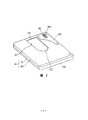
Fig. 1 and Fig. 2 are the summary diagrammatic sketch of the disc box 100 of one embodiment of the invention, and Fig. 1 overlooks oblique view, and Fig. 2 looks up oblique view.
Below, referring to Fig. 1 and Fig. 2 summary description disc box 100.Among Fig. 1, the application's disc box 100 comprises shell 101.Shell 101 is made of plastic first half shell 110 and Lower Half shell 120.The direction of insertion of the direction of insertion of the relative drive unit of top formation indicating panel film magazine of first half shell 110 is represented portion 111.And on a side of shell 101, forming pallet insertion mouth 102, the cross sectional shape of shell 101 is made and is roughly コ shape.Insert mouthful 102 two places of nearby dividing right and left on one side along pallet, be provided with the pallet lock hole 112 of locking usefulness.
Can insert the pallet of extracting out 130 to shell 101, make with for example synthetic resin material, substantial middle position above it has the spill storage part 131 of the circle of put disc, and corresponding outer shell side head access aperture 121 reaches outer shell side mandrel patchhole 122(referring to Fig. 2) the position form pallet side head access aperture 132(continuously referring to Fig. 3) and pallet side's mandrel patchhole 133.And top near preocular two places of dividing right and left of pallet 130 are provided with the elastic component 134 of corresponding pallet lock hole 112.This elastic component is because of forming groove crack 136, thereby can displacement when being subjected to arrow Z direction pressing and have elastic force.The top locking teat 135 that is provided with respectively of elastic component 134.Because after pallet 130 inserted in the shell 101, locking teat 135 just embedded pallet lock hole 112, thereby opposite shell 101 pallets 130 are locked, stopped the pallet extraction.
On the other hand, on Lower Half shell 120, as shown in Figure 2, form outer shell side head access aperture 121 and outer shell side mandrel patchhole 122 continuously.And the printing base plate 150 that external storage spare (not shown) etc. is housed is contained on the Lower Half shell 120, on the institute's allocation below printing base plate 150 contact terminal 151 is set.
Disc shaped record carriers such as CD (to call " record disc " in the following text) 160 can be deposited in the spill storage part 131 of pallet 130 with passing in and out.And it is consistent with the thickness direction of disc box 100 with the pressing direction Z of elastic component 134 that disc box 100 is made locking, and pallet 130 inserts, extracts out direction Y' to shell 101, and X ' is vertical to insertion, the extraction direction of drive unit with disc box 100.
The details of Fig. 3 to Fig. 8 indicating panel film magazine 100, Fig. 3 is the exploded perspective view of disc box; Fig. 4 is the phantom view of state before the clamping of expression information-recording disk sheet; Fig. 5 is the phantom view of expression information-recording disk sheet clamp position; Fig. 6 is the phantom view of expression the 2nd shutter bearing state; Fig. 7 is the amplification plan view around the locking teat; Fig. 8 is the amplification view around the locking teat.
Below referring to Fig. 3 to Fig. 8, describe disc box 100 in detail.Among Fig. 3,, form the round hole 113 bigger than the mandrel patchhole of record disc 160 at the substantial middle place of first half shell 110.Form step 116 in the perforate 113, support clamper part 115 and rotate freely (referring to Fig. 4).Cover plate 114 is fixing in the perforate 113 with proper methods such as welding, in case clamper part 115 comes off.
When not using, record disc 160 is accommodated to be bearing in the pallet 130, and as shown in Figure 4, clamper part 115 is bearing on the step 116 by its deadweight.
When disc box 100 is loaded onto drive unit, then by set shutter opening pin (not shown) in the drive unit, the 1st shutter 140 automatically slides, open formed outer shell side head access aperture 121 on the Lower Half shell 120, outer shell side mandrel patchhole 122, pallet side's head access aperture 132 and pallet side's mandrel patchhole 133, as shown in Figure 5, insert mandrel 170, the central part of record disc 160 by resilient clamp between mandrel 170 and clamper part 115.
Handle 137 vicinity of nearly pallet 130 are provided with two elastic components 134 across a certain distance, form locking teat 135 on free end one side direction of elastic component 134.And around this elastic component 134, form the groove crack 136 be roughly U-shaped, when downward pressing elastic component 134, have elastic force with regard to displacement.(referring to Fig. 7, Fig. 8) also has, and forms pallet lock hole 112 at the opposed locations place with the locking teat 135 of first half shell 110.
Therefore, as shown in Figure 8, under the state of pressing elastic component 134 not, elastic component 134 is the level of state, combine with it in the pallet lock hole 112 of locking teat 135 insertion first half shells 110, pallet 130 just is in and can not promptly be in the lock state from the state of shell 101 extractions.
Yet, when extracting pallet 130 out, the user can be by using left and right sides thumb along arrow Z direction (thickness direction of shell 101) difference pressing elastic component 134, by the unlock combination of teat 135 and pallet lock hole 112 of limit, the limit is drawn pallet 130 at the moment to oneself, just can extract out, can take out the record disc of depositing separately thus from shell 101.Like this, even child also can easily insert with little hand and extract pallet 130 out.
With the contact terminal 151(of Lower Half shell 120 referring to Fig. 2) the opposed locations place, form terminal hole 152.Terminal hole 152 carries out switch by the 2nd shutter 141 as shown in Figure 3.The 2nd shutter 141 and the 1st shutter 140 can be in the shell 101 inboard formed same direction slips in wall 123 upper edges (referring to Fig. 4, Fig. 6) of leading.Give two shutters 140,141 elastic force with a spring 142 towards closing direction.And, open the state of terminal hole 152 after expression the 2nd shutter 141 slides among Fig. 2 for ease of explanation.Be disc box 100 when not using, close terminal hole 152 with the 2nd shutter 141.
Battery carrier 154 by button cell 155 is deposited under the inboard state press from the side of Lower Half shell 120 into, insert with battery 155 and to be arranged in the framework of printing on the base plate 150 153.
This embodiment has illustrated the situation of the pallet lock hole 112 that perforate is set, and replaces the hole but also can form recess.In addition, also can jut be set, at elastic component 134 square one-tenth pallet lock hole or recesses shell 101 sides.
Also have, the situation that this embodiment represents be the combination member that pallet lock hole 112 and elastic component 134 constitutes is arranged at about, but also can strengthen the spill storage part 131 of pallet 130 and the interval of handle portion 137, to the insertion of disc drive appts, the substantial middle position of extraction direction X ' 1 group of combination member is set at the disc box.
In addition, this embodiment illustrated pallet insert mouthfuls 102 nearby form combination member, but so long as do not hinder the rotation and the 1st of record disc 160, the switch of the 2nd shutter, any position can form combination member.
Fig. 9 represents other embodiments of the invention.This embodiment disc box 200 is the same with the embodiment of Fig. 1 and Fig. 2, is made of first half shell 210, Lower Half shell 220, record disc 160 and pallet 230 etc.And in this embodiment, the pallet that pallet lock hole 212 is formed on shell 201 inserts on mouth 202 two lateral surfaces nearby.Also have,, form otch 236 because of elastic component 234 is located at the nearly left and right sides of part at the moment, thereby during along arrow Z' direction pressing, because of displacement has elastic force.Be located at the side of elastic component 234 respectively because of locking teat 235, after in the pallet 230 insertion shells 210, locking teat 235 just embeds pallet lock hole 212, and just energy is locked with respect to shell 201 pallets 230, and prevention pallet 230 is drawn out of.
When extracting pallet 230 out, the user can by with the thumb of a hand and forefinger or middle finger along the center (arrow Z ') direction pressing left and right sides elastic component 234, when unlocking the combination of teat 235 and pallet lock hole 212, pallet 230 is drawn in face of own, thereby extract out from shell 201.So just can take out the record disc of depositing separately.Therefore, if user's hand is big, singlehanded just can the insertion extracted pallet 230 out.
In addition, the same with the embodiment of Fig. 1 and Fig. 2, among this embodiment structure make pallet 230 to the insertion of shell, to extract direction out vertical to insertion, the extraction direction of drive unit with disc box 200.And, among this embodiment, the pressing direction Z' of elastic component 234 with to the insertion of drive unit, to extract direction X' out consistent.
The same with the embodiment of Fig. 1 and Fig. 2, also can be in the present embodiment by forming the pallet lock hole 212 that recess substitutes perforate.But also can projection be set shell 201 sides, at elastic component 234 1 square one-tenth pallet lock hole or recesses.
Have, as other embodiment, also can sliding component be set at the handle portion of pallet, the part of sliding component is combined with the combination member that is formed at shell one side, formation can be in conjunction with locking pallet and shell with deviating from.And the same with aforementioned two embodiment, among this embodiment, pallet is selected to vertical to insertion, the extraction direction of drive unit with the disc box to insertion, the extraction direction of shell.
As mentioned above, the present invention is because pallet is vertical to insertion, the extraction direction of drive unit with the disc box to insertion, the extraction direction of shell, can eliminate when drive unit is extracted the disc box out after careless the unlocking, shell is stayed in the drive unit, the drawback of damage record disc seeks to improve functional reliability to record disc exposing extraction under the state.
If not, just can not take out pallet, so record disc situation such as fly out pallet or disc box can not take place to extract out carelessly fall the time because of along pressing combination member limit, the direction limit pull that unlocks.Consequently can prevent to stain, damage record disc, prevent the data read errors that the record disc damage causes.
Fig. 1 is the oblique view of one embodiment of the invention disc box 100;
Fig. 2 is the oblique view of being looked from Fig. 1 embodiment bottom surface;
Fig. 3 is the exploded perspective view of Fig. 1 embodiment;
Fig. 4 is a phantom view, the partial sectional view of state before the clamping of record disc 106 among presentation graphs 1 embodiment;
The partial sectional view of the clamp position of record disc 106 among Fig. 5 presentation graphs 1 embodiment;
Fig. 6 is a phantom view, the holding state partial sectional view of the 2nd shutter 141 among presentation graphs 1 embodiment;
Fig. 7 is near the amplification plan view the locking teat 135 among Fig. 1 embodiment;
Fig. 8 is near the amplification view the locking teat 135 among Fig. 1 embodiment;
Fig. 9 is the oblique view of other embodiment disc box 200 of the present invention;
Figure 10 is the vertical view as the application's background technology disc box 1.
It below is symbol description, 100,200: the disc box, 101,201: shell, 102,202: pallet inserts mouth, 110,210: first half shell, 111,211: direction of insertion is represented portion, 112,212: pallet lock hole, 120,220: the Lower Half shell, 121: outer shell side head access aperture, 122: outer shell side mandrel patchhole, 130,230: pallet, 131,231: the spill storage part, 133,233: pallet side's mandrel patchhole, 134,234: elastic component, 135,235: locking teat, 136,236: the groove crack, 160: record disc, X, X ': direction, Y are extracted in the insertion of disc box out, Y ': the insertion of pallet, extract direction out, Z, Z ': the pressing direction of elastic component.
Claims (5)
1, a kind of its internal storage disc shaped record carrier, be contained in employed disc box on the disc drive appts, it is characterized in that having 1. that there is the pallet storing space its inside, along there being pallet to insert mouthful to place, disc drive appts direction of insertion one side, and flat shape is tetragonal flat package; 2. have the spill storage part that is used for tray sheet record carrier on the one plane, and can insert the pallet in the above-mentioned pallet storing space that can insert above-mentioned shell with taking out; 3. be formed on the above-mentioned shell, be used for above-mentioned pallet storing under the internal state of pallet storing space, making locking can be the 1st combination member that can take off; The 2nd combination member that forms on the above-mentioned pallet at 4. corresponding above-mentioned the 1st combination member place; Be selected to disc box to insertion or the extraction direction of disc drive appts vertical to the insertion or the extraction direction of above-mentioned shell above-mentioned pallet.
2, disc box according to claim 1, it is characterized in that above-mentioned the 2nd combination member along the disc box when disc drive appts inserts or extracts the direction pressing out, remove locking with above-mentioned the 1st combination member.
When 3, disc box according to claim 1, above-mentioned the 2nd combination member are subjected to disc box thickness direction pressing, remove locking with the 1st combination member.
4, disc box according to claim 1 is characterized in that the 1st above-mentioned combination member is located near the above-mentioned pallet insertion mouth of above-mentioned shell, and above-mentioned the 2nd combination member is located on the above-mentioned pallet of corresponding the 1st combination member position.
5, disc box according to claim 1 is characterized in that above-mentioned the 1st combination member is located at separately two places of above-mentioned shell, and above-mentioned the 2nd combination member is located at respectively on the position of corresponding the 1st combination member.
Applications Claiming Priority (2)
| Application Number | Priority Date | Filing Date | Title |
|---|---|---|---|
| JP4320238A JPH06168566A (en) | 1992-11-30 | 1992-11-30 | Disk cartridge |
| JP320238/92 | 1992-11-30 |
Publications (1)
| Publication Number | Publication Date |
|---|---|
| CN1090423A true CN1090423A (en) | 1994-08-03 |
Family
ID=18119268
Family Applications (1)
| Application Number | Title | Priority Date | Filing Date |
|---|---|---|---|
| CN93120558A Pending CN1090423A (en) | 1992-11-30 | 1993-11-30 | The disc box |
Country Status (14)
| Country | Link |
|---|---|
| JP (1) | JPH06168566A (en) |
| KR (1) | KR940012322A (en) |
| CN (1) | CN1090423A (en) |
| AU (1) | AU682476B2 (en) |
| BR (1) | BR9304850A (en) |
| CA (1) | CA2110203A1 (en) |
| DE (1) | DE4340601A1 (en) |
| ES (1) | ES2077521B1 (en) |
| FR (1) | FR2698709A1 (en) |
| GB (1) | GB2272990B (en) |
| IT (1) | IT1265235B1 (en) |
| MX (1) | MX9307434A (en) |
| NL (1) | NL193095C (en) |
| SE (1) | SE9303980L (en) |
Cited By (4)
| Publication number | Priority date | Publication date | Assignee | Title |
|---|---|---|---|---|
| CN1082701C (en) * | 1995-10-30 | 2002-04-10 | 株式会社东芝 | Disk sheet case device |
| US6445677B1 (en) | 1998-05-23 | 2002-09-03 | Samsung Electronics Co., Ltd. | Cartridge for an information recording medium |
| CN1324608C (en) * | 1999-06-04 | 2007-07-04 | 松下电器产业株式会社 | Cassette record disk |
| CN111798877A (en) * | 2019-04-09 | 2020-10-20 | 光宝电子(广州)有限公司 | Disk library storage system and cassette box for the same |
Families Citing this family (11)
| Publication number | Priority date | Publication date | Assignee | Title |
|---|---|---|---|---|
| US6044058A (en) * | 1993-08-24 | 2000-03-28 | Matsushita Electric Industrial Co., Ltd. | Adaptor cartridge for mounting a second disk in a device designed to mount a first-disk cartridge |
| US5991260A (en) * | 1995-02-20 | 1999-11-23 | Hitachi, Ltd. | Disk cartridge and disk device using the same |
| US5913419A (en) * | 1995-05-29 | 1999-06-22 | U.S. Philips Corporation | Combination of a support for a disc-shaped recording medium and a holder for the support |
| EP0794532B1 (en) * | 1995-09-21 | 2003-11-26 | Matsushita Electric Industrial Co., Ltd. | Cartridge with removable disk |
| JP3516089B2 (en) * | 1996-02-26 | 2004-04-05 | 日立マクセル株式会社 | Disk cartridge |
| US6205115B1 (en) | 1997-09-10 | 2001-03-20 | Tdk Corporation | Disc cartridge |
| EP0961272B1 (en) | 1997-12-16 | 2001-02-28 | Matsushita Electric Industrial Co., Ltd. | Disk cartridge |
| JPH11185423A (en) * | 1997-12-24 | 1999-07-09 | Tdk Corp | Disc cartridge |
| JP2000207864A (en) | 1999-01-08 | 2000-07-28 | Alps Electric Co Ltd | Optical disk cartridge |
| JP3840346B2 (en) | 1999-01-08 | 2006-11-01 | アルプス電気株式会社 | Optical disc cartridge |
| DE60000078D1 (en) * | 1999-06-04 | 2002-04-04 | Matsushita Electric Ind Co Ltd | disk cartridge |
Family Cites Families (6)
| Publication number | Priority date | Publication date | Assignee | Title |
|---|---|---|---|---|
| GB2047942B (en) * | 1979-04-06 | 1983-02-02 | Rca Corp | Record handling mechanism for caddy tyre record disc player |
| US4316539A (en) * | 1980-12-10 | 1982-02-23 | Rca Corporation | Video disc caddy |
| US4463849A (en) * | 1983-05-23 | 1984-08-07 | Rca Corporation | Video disc caddy |
| NL8601884A (en) * | 1986-07-21 | 1988-02-16 | Philips Nv | PLATE CASSETTE. |
| EP0267644A1 (en) * | 1986-11-03 | 1988-05-18 | Koninklijke Philips Electronics N.V. | System for recording/reading information on/from a disc, comprising a disc cassette and an apparatus |
| NL8702222A (en) * | 1987-09-17 | 1989-04-17 | Philips Nv | SYSTEM FOR REGISTERING / READING INFORMATION ON / FROM A PLATE. |
-
1992
- 1992-11-30 JP JP4320238A patent/JPH06168566A/en not_active Withdrawn
-
1993
- 1993-11-24 AU AU51875/93A patent/AU682476B2/en not_active Ceased
- 1993-11-26 KR KR1019930025455A patent/KR940012322A/en not_active Application Discontinuation
- 1993-11-26 MX MX9307434A patent/MX9307434A/en unknown
- 1993-11-26 ES ES09302497A patent/ES2077521B1/en not_active Expired - Lifetime
- 1993-11-26 BR BR9304850A patent/BR9304850A/en not_active Application Discontinuation
- 1993-11-26 FR FR9314186A patent/FR2698709A1/en active Granted
- 1993-11-29 IT IT93MI002510A patent/IT1265235B1/en active IP Right Grant
- 1993-11-29 DE DE4340601A patent/DE4340601A1/en not_active Withdrawn
- 1993-11-29 GB GB9324578A patent/GB2272990B/en not_active Expired - Fee Related
- 1993-11-29 CA CA002110203A patent/CA2110203A1/en not_active Abandoned
- 1993-11-30 NL NL9302078A patent/NL193095C/en not_active IP Right Cessation
- 1993-11-30 CN CN93120558A patent/CN1090423A/en active Pending
- 1993-11-30 SE SE9303980A patent/SE9303980L/en not_active Application Discontinuation
Cited By (11)
| Publication number | Priority date | Publication date | Assignee | Title |
|---|---|---|---|---|
| CN1082701C (en) * | 1995-10-30 | 2002-04-10 | 株式会社东芝 | Disk sheet case device |
| US6445677B1 (en) | 1998-05-23 | 2002-09-03 | Samsung Electronics Co., Ltd. | Cartridge for an information recording medium |
| US6728200B2 (en) | 1998-05-23 | 2004-04-27 | Samsung Electronics Co., Ltd. | Cartridge for an information recording medium |
| US6912724B2 (en) | 1998-05-23 | 2005-06-28 | Samsung Electronics Co., Ltd. | Cartridge for an information recording medium |
| US6931655B2 (en) | 1998-05-23 | 2005-08-16 | Samsung Electronics Co., Ltd. | Cartridge for an information recording medium |
| US7185351B2 (en) | 1998-05-23 | 2007-02-27 | Samsung Electronics Co., Ltd. | Cartridge for an information recording medium |
| US7222352B2 (en) | 1998-05-23 | 2007-05-22 | Samsung Electronics Co., Ltd. | Cartridge for an information recording medium |
| US7519981B2 (en) | 1998-05-23 | 2009-04-14 | Samsung Electronics Co., Ltd. | Cartridge for an information recording medium |
| CN1324608C (en) * | 1999-06-04 | 2007-07-04 | 松下电器产业株式会社 | Cassette record disk |
| CN111798877A (en) * | 2019-04-09 | 2020-10-20 | 光宝电子(广州)有限公司 | Disk library storage system and cassette box for the same |
| US11094348B2 (en) | 2019-04-09 | 2021-08-17 | Lite-On Electronics (Guangzhou) Limited | Disc library storage system and disc cartridge used thereof |
Also Published As
| Publication number | Publication date |
|---|---|
| JPH06168566A (en) | 1994-06-14 |
| DE4340601A1 (en) | 1994-06-01 |
| IT1265235B1 (en) | 1996-10-31 |
| AU682476B2 (en) | 1997-10-09 |
| GB2272990A (en) | 1994-06-01 |
| ES2077521B1 (en) | 1998-01-16 |
| AU5187593A (en) | 1994-06-09 |
| KR940012322A (en) | 1994-06-23 |
| FR2698709A1 (en) | 1994-06-03 |
| ITMI932510A0 (en) | 1993-11-29 |
| GB9324578D0 (en) | 1994-01-19 |
| CA2110203A1 (en) | 1994-05-31 |
| FR2698709B1 (en) | 1997-02-21 |
| MX9307434A (en) | 1994-08-31 |
| ITMI932510A1 (en) | 1995-05-29 |
| NL9302078A (en) | 1994-06-16 |
| SE9303980L (en) | 1994-05-31 |
| NL193095C (en) | 1998-10-05 |
| BR9304850A (en) | 1994-08-16 |
| SE9303980D0 (en) | 1993-11-30 |
| ES2077521R (en) | 1997-05-16 |
| ES2077521A2 (en) | 1995-11-16 |
| GB2272990B (en) | 1996-04-10 |
| NL193095B (en) | 1998-06-02 |
Similar Documents
| Publication | Publication Date | Title |
|---|---|---|
| CN1090423A (en) | The disc box | |
| TW396334B (en) | Disk tray and tray allocation box | |
| US7249364B2 (en) | Methods and systems for scaling and rotating an image in a single operation | |
| JPH0346910B2 (en) | ||
| TWI228706B (en) | CD drivng device | |
| US5881872A (en) | Four-part package for storage media | |
| US7146625B2 (en) | Disc cartridge and disc drive using the same | |
| US5984094A (en) | Hinge for storage media package | |
| TWI226046B (en) | Cassette for accommodating recording medium | |
| US5984093A (en) | Automatic storage media release mechanism for storage media package | |
| JPH08504995A (en) | Optical compact disc storage and loading cassette | |
| US6123190A (en) | Disc cartridge storage case | |
| JPS583312B2 (en) | Cartridge for disc-shaped recording media | |
| JP3313562B2 (en) | Disk cartridge and disk device using the same | |
| JPH0523511Y2 (en) | ||
| JP3051286B2 (en) | Incorrect disk insertion prevention mechanism in autochanger device | |
| TW409243B (en) | Disc cartridge | |
| JP2903585B2 (en) | Disc loading mechanism | |
| JPS606935Y2 (en) | Cartridge | |
| US20040212927A1 (en) | Drive device | |
| TW569190B (en) | Disc case | |
| JPS6134605Y2 (en) | ||
| KR0113722Y1 (en) | Disk cartridge case | |
| JPH09198834A (en) | Magnetic disk cartridge and magnetic disk driving device | |
| JPH07206068A (en) | Carrying case |
Legal Events
| Date | Code | Title | Description |
|---|---|---|---|
| C06 | Publication | ||
| PB01 | Publication | ||
| C10 | Entry into substantive examination | ||
| SE01 | Entry into force of request for substantive examination | ||
| C01 | Deemed withdrawal of patent application (patent law 1993) | ||
| WD01 | Invention patent application deemed withdrawn after publication |