Disclosure of Invention
The technical problem to be solved by the application is that the data being transmitted is lost due to the restart of the FPGA, and the lost data cannot be recovered. A data recovery method and apparatus are provided.
In a first aspect, an embodiment of the present application provides a data recovery method, which is applied to a data receiving end, and includes:
if the first message receiving abnormity is detected, a message retransmission request is sent to a data sending end; the message retransmission request carries a message identifier of a first message, so that the data sending end can read the first message from a retransmission cache according to the message identifier and send the first message to the data receiving end;
if a message retransmission response sent by the data sending end is received, stopping sending the message retransmission request to the data sending end; the message retransmission response represents that the data sending end has sent the first message to the data receiving end.
Optionally, if a message retransmission response sent by the data sending end is received, stopping sending a message retransmission request to the data sending end includes:
and if the message retransmission response sent by the data sending end is received and the message retransmission response is verified to be passed, stopping sending a message retransmission request to the data sending end.
Optionally, if a message retransmission response sent by the data sending end is received, stopping sending a message retransmission request to the data sending end includes:
and if the message retransmission response sent by the data sending end is received within a preset time period, stopping sending a message retransmission request to the data sending end.
Optionally, the method further includes:
and if the message retransmission response sent by the data sending end is not received within a preset time period, stopping sending a message retransmission request to the data sending end and giving an abnormal signal.
Optionally, the address range of the retransmission cache is from 0 to M, and the packet identifier of the first packet is obtained by performing a remainder operation on the packet sequence number of the first packet and (M +1), where the packet sequence number includes a sequence number of an effective packet received by the data receiving end.
Optionally, if the data sending end sends a packet to the data receiving end in a multi-path packet parallel sending manner, the retransmission cache further stores identification information of the multi-path packet, where the identification information is used to identify an effective packet in the multi-path packet;
the data sending end reads the first message from a retransmission cache according to the message identifier, and the method comprises the following steps:
and the data sending end reads the first message from the storage address according to the message identification and the identification information.
Optionally, the method further includes:
and if the effective message is successfully received, sending a successful receiving response to the data sending end so that the data sending end deletes the successfully received effective message from the retransmission cache.
Optionally, the method further includes:
and receiving a second message sent by the data sending end, wherein the second message is sent to the data receiving end after the data sending end sends the first message, but is not successfully received by the data receiving end.
In a second aspect, an embodiment of the present application provides a data recovery apparatus, which is applied to a data receiving end, and includes:
a request sending unit, configured to send a message retransmission request to the data sending end if it is detected that the first message is received abnormally; the message retransmission request carries a message identifier of a first message, so that the data sending end can read the first message from a retransmission cache according to the message identifier and send the first message to the data receiving end;
a sending stopping unit, configured to stop sending the message retransmission request to the data sending end if a message retransmission response sent by the data sending end is received; the message retransmission response represents that the data sending end has sent the first message to the data receiving end.
Optionally, the stop sending unit is specifically configured to:
and if the message retransmission response sent by the data sending end is received and the message retransmission response is verified to be passed, stopping sending a message retransmission request to the data sending end.
Optionally, the stop sending unit is specifically configured to:
and if the message retransmission response sent by the data sending end is received within a preset time period, stopping sending a message retransmission request to the data sending end.
Optionally, the apparatus further comprises:
and the abnormal signal generating unit is used for stopping sending a message retransmission request to the data sending end and giving an abnormal signal if the message retransmission response sent by the data sending end is not received within a preset time period.
Optionally, the address range of the retransmission cache is from 0 to M, and the packet identifier of the first packet is obtained by performing a remainder operation on the packet sequence number of the first packet and (M +1), where the packet sequence number includes a sequence number of an effective packet received by the data receiving end.
Optionally, if the data sending end sends a packet to the data receiving end in a multi-path packet parallel sending manner, the retransmission cache further stores identification information of the multi-path packet, where the identification information is used to identify an effective packet in the multi-path packet;
the data sending end reads the first message from a retransmission cache according to the message identifier, and the method comprises the following steps:
and the data sending end reads the first message from the storage address according to the message identification and the identification information.
Optionally, the apparatus further comprises:
and the response sending unit is used for sending a successful receiving response to the data sending end if the effective message is successfully received, so that the data sending end deletes the successfully received effective message from the retransmission cache.
Optionally, the apparatus further comprises:
a message receiving unit, configured to receive a second message sent by the data sending end, where the second message is a message that is sent to the data receiving end by the data sending end after sending the first message, but is not successfully received by the data receiving end.
Compared with the prior art, the embodiment of the application has the following advantages:
the data recovery method and device provided by the embodiment of the application comprise the following steps: if the first message receiving abnormity is detected, a message retransmission request is sent to a data sending end; the message retransmission request carries a message identifier of a first message, so that the data sending end can read the first message from a retransmission cache according to the message identifier and send the first message to the data receiving end; if a message retransmission response sent by the data sending end is received, stopping sending a message retransmission request to the data sending end; the message retransmission response represents that the data sending end has sent the first message. Therefore, by using the data recovery method and the device provided by the embodiment of the application, the data receiving end can send a message retransmission request to the data sending end when the first message is received abnormally, and the message retransmission request carries the message identifier of the first message, so that the message sending end can determine which message is abnormal, and then send the first message to the data receiving end again, and after receiving a message retransmission response, the data sending end can determine that the first message has been sent to the data receiving end again, and thus the first message is determined to be retransmitted. That is to say, with the scheme provided in the embodiment of the present application, even if the first packet is lost during the reset due to the abnormal reset of the physical layer, the first packet can be recovered after the reset is completed by sending the packet retransmission request.
Detailed Description
In order to make the technical solutions of the present application better understood, the technical solutions in the embodiments of the present application will be clearly and completely described below with reference to the drawings in the embodiments of the present application, and it is obvious that the described embodiments are only a part of the embodiments of the present application, and not all of the embodiments. All other embodiments, which can be derived by a person skilled in the art from the embodiments given herein without making any creative effort, shall fall within the protection scope of the present application.
Through research, the inventor of the present application finds that, in the prior art, a physical layer reset, for example, a fiber is unplugged, may cause a data link layer reset, thereby causing a restart of the FPGA, further causing loss of data being transmitted, and the lost data cannot be recovered.
In order to solve the above problem, an embodiment of the present application provides a data recovery method and apparatus, including: if the first message receiving abnormity is detected, a message retransmission request is sent to a data sending end; the message retransmission request carries a message identifier of a first message, so that the data sending end can read the first message from a retransmission cache according to the message identifier and send the first message to the data receiving end; if a message retransmission response sent by the data sending end is received, stopping sending a message retransmission request to the data sending end; the message retransmission response represents that the data sending end has sent the first message. Therefore, by using the data recovery method and the device provided by the embodiment of the application, the data receiving end can send a message retransmission request to the data sending end when the first message is received abnormally, and the message retransmission request carries the message identifier of the first message, so that the message sending end can determine which message is abnormal, and then send the first message to the data receiving end again, and after receiving a message retransmission response, the data sending end can determine that the first message has been sent to the data receiving end again, and thus the first message is determined to be retransmitted. That is to say, with the scheme provided in the embodiment of the present application, even if the first packet is lost during the reset due to the abnormal reset of the physical layer, the first packet can be recovered after the reset is completed by sending the packet retransmission request.
Various non-limiting embodiments of the present application are described in detail below with reference to the accompanying drawings.
Exemplary method
Referring to fig. 1, the figure is a schematic flowchart of a data recovery method according to an embodiment of the present application.
The data recovery method provided by the embodiment of the application is applied to a data receiving end, and the data receiving end can be a board card comprising an FPGA.
The method may be implemented, for example, by the following steps S101-S102.
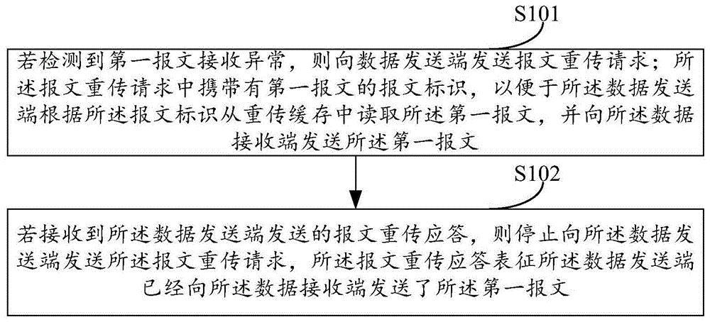
S101: if the first message receiving abnormity is detected, a message retransmission request is sent to a data sending end; the message retransmission request carries a message identifier of a first message, so that the data sending end reads the first message from a retransmission cache according to the message identifier and sends the first message to the data receiving end.
In this embodiment of the present application, the first packet refers to a packet that is being received by a data receiving end when the FPGA is reset.
It can be understood that if the FPGA is reset, the data receiving end cannot normally receive data. The first message receiving exception mentioned here can be understood to be that the FPGA is in a reset state to some extent.
It should be noted that, generally, when a message is transmitted between a data sending end and a data receiving end, in order to verify whether the message is tampered during transmission, when the data sending end sends the message to the data receiving end, a checksum (e.g., CRC checksum) corresponding to the message may be sent to the data receiving end, so that when the data receiving end receives the message, the checksum is used to verify whether the received message is a correct message.
If the FPGA is reset, the checksum of the message received by the receiver may be in error, and in the embodiment of the present application, it may be detected that the first message is received abnormally, for example, the checksum of the first message is detected in error.
In this embodiment of the present application, the message retransmission request is used to request the data sending end to send the first message to the data receiving end again.
It should be noted that, in this embodiment of the application, after the data sending end sends the message to the data receiving end, the message may also be stored in the retransmission cache. When the message needs to be retransmitted, the message is read from the retransmission buffer and sent to the data receiving end again.
It should be noted that, in the embodiment of the present application, the retransmission buffer may be a RAM in an FPGA.
In this embodiment, the message retransmission request carries a message identifier of the first message. The message identifier is used for indicating a storage address of the first message in the retransmission cache.
The layout system of the embodiment of the application defines the packet identifier, and as an example, if the address range of the retransmission cache is from 0 to M, the packet identifier of the first packet is obtained by performing a remainder operation on a packet sequence number of the first packet and (M +1), where the packet sequence number includes a sequence number of an effective packet received by the data receiving end. For example, if the value of M is decimal 127, and the message serial number of the first message is decimal 2, the identifier of the first message is decimal 2.
In this embodiment of the present application, M is a positive integer greater than 0, and the specific value of M is not specifically limited in this embodiment of the present application, and may be determined according to an actual situation, for example, according to the remaining resources of the FPGA.
It can be understood that, since the packet identifier is used to indicate a storage address of the first packet in the retransmission cache, the data sending end may read the first packet from the retransmission cache according to the packet identifier and send the first packet to the data receiving end.
It should be noted that, in this embodiment of the application, if a message retransmission response sent by the data sending end is not received, the data receiving end may continuously send a message retransmission request to the data sending end, that is, if the data receiving end does not receive the message retransmission response sent by the data sending end after sending a message retransmission request to the data sending end, the data receiving end may continuously send the message retransmission request to the data sending end.
S102: and if a message retransmission response sent by the data sending end is received, stopping sending the message retransmission request to the data sending end, wherein the message retransmission response represents that the data sending end has sent the first message to the data receiving end.
It should be noted that, in the embodiment of the present application, if a message retransmission response sent by the data sending end is received, it may be characterized to a certain extent that the FPGA of the data receiving end is reset, so that the message may be normally received.
In this embodiment of the application, after the data sending end sends the first message to the data receiving end again, a message retransmission response is sent to the data receiving end, and if the data receiving end receives the message retransmission response, the data receiving end can represent that the data receiving end has received the first message retransmitted by the data sending end to a certain extent. At this time, the data receiving end may stop sending the message retransmission request to the data sending end, thereby entering a normal message receiving state.
When the steps S101 to S102 are implemented in an FPGA, the steps may be implemented by a state-state machine (FSM), for example, a three-stage state machine.
Therefore, by using the data recovery method provided by the embodiment of the present application, the data receiving end may send a message retransmission request to the data sending end when the first message is received abnormally, and because the message retransmission request carries the message identifier of the first message, the message identifier may enable the message sending end to determine which message is abnormal, so as to send the first message to the data receiving end again, and after receiving a message retransmission response, it may be determined that the data sending end has sent the first message to the data receiving end again, so as to determine that the first message has been retransmitted. That is to say, with the scheme provided in the embodiment of the present application, even if the first packet is lost during the reset due to the abnormal reset of the physical layer, the first packet can be recovered after the reset is completed by sending the packet retransmission request.
It will be appreciated that the FPGA reset may be embodied as a check and error of data received by the data receiver. In order to further determine that the FPGA of the data receiving end is reset, the message can be normally received. In a possible implementation manner of the embodiment of the present application, when the step S102 is implemented specifically, the following steps may be performed: and if the message retransmission response sent by the data sending end is received and the message retransmission response is verified to be passed, stopping sending a message retransmission request to the data sending end.
It should be noted that, the passing of the message retransmission acknowledgement check mentioned herein may be, for example, passing of a CRC of the message retransmission acknowledgement check.
It can be understood that, when the message retransmission response is checked to pass, it can be characterized that the data receiving end receives a correct message retransmission response, and further, it can be characterized that the data receiving end receives the first message sent by the data sending end.
As described above, if a message retransmission response sent by the data sending end is not received, the data receiving end may continuously send a message retransmission request to the data sending end. In this embodiment of the present application, in consideration that in practical application, if the duration of the reset signal is too long, the above method stays in step S101 all the time, and the continuous sending of the message retransmission request needs to consume resources of the FPGA, therefore, in an implementation manner of this embodiment of the present application, step S102 may be implemented specifically as follows: and if the message retransmission response sent by the data sending end is received within a preset time period, stopping sending a message retransmission request to the data sending end.
It should be noted that the preset time period mentioned herein is a time period taking a time when the data receiving side first sends a message retransmission request as a starting time. The preset time period is not specifically limited in the embodiment of the present application, and the preset time period may be embodied as a specific value, for example, 5ms, and the preset time period may also be embodied as the number of times of the message retransmission request sent by the data receiving end, for example, 5 times.
For example, if the message retransmission response is received within 5ms from the time when the data receiving side first sends the message retransmission request, the message retransmission request is stopped being sent to the data sending side, and the normal message receiving state is entered; and if the message retransmission response is received after the 3-time message retransmission request is sent, stopping sending the message retransmission request to the data sending end and entering a normal message receiving state.
In an example of the embodiment of the present application, if a message retransmission response sent by the data sending end is not received within a preset time period, it may be considered that a duration of the abnormal reset may be relatively long, and in order to save resources of the FPGA, sending a message retransmission request to the data sending end may be stopped, and an abnormal signal is given to remind a maintainer that the FPGA is abnormally reset.
It can be understood that, in practical applications, when a data sending end sends a packet to a data receiving end, a parallel sending manner may be adopted, for example, there may be multiple data sending ports, and multiple data sending ports may send packets at the same time, that is, multiple packets may be sent at the same time. It is understood that in the multiple messages sent in parallel, not all messages are valid messages, and for example, some invalid messages or null messages may exist. While invalid and null messages are meaningless to the data receiving end.
In an implementation manner of the embodiment of the present application, if the data sending end sends a packet to the data receiving end in a manner of parallel sending of multiple packets of packets, the retransmission cache further stores identification information of the multiple packets of packets, where the identification information is used to identify an effective packet in the multiple packets of packets.
In this embodiment of the present application, the multiple paths of messages that are sent in parallel and the identification information of the multiple paths of messages may be stored in a certain address of the retransmission cache. For example, as can be understood in conjunction with fig. 2, fig. 2 is a schematic structural diagram of data stored in a retransmission buffer according to an embodiment of the present application. Fig. 2 illustrates data stored in address 0 of the retransmission buffer by taking parallel transmission of 4-way messages as an example. Wherein 201 is the identification information of the 4-way packet, 4' b0101 identifies that packet 202 is an empty packet, packet 203 is an effective packet, packet 204 is an empty packet, and packet 205 is an effective packet.
In this embodiment of the present application, since the first packet is an effective packet and a null packet is included in the packets stored in the retransmission cache, in order to determine a specific location of the first packet in the retransmission cache, in this embodiment of the present application, the data sending end may read the first packet from the storage address according to the packet identifier and the identifier information.
Specifically, the storage address of the first packet may be determined according to the packet identifier and the identifier information in the preset storage range in the retransmission cache, and then a specific storage location of the first packet in the storage address of the first packet is determined according to the identifier information of the storage address of the first packet, so as to read the first packet from the storage location.
It should be noted that the preset storage range refers to a storage range between the first address and the second address. The first address refers to a tail address of the retransmission cache, the second address refers to a head address of the retransmission cache, wherein the head address stores a message which is sent by the data sending end most recently and identification information corresponding to the message, and the tail address stores a message which is sent by the data sending end before and identification information corresponding to the message. And the value of the tail address is smaller than that of the head address, and the message stored in the previous address of the tail address is an invalid message.
It should be noted that, in this embodiment of the present application, in consideration of the limited storage space of the retransmission cache, in this embodiment of the present application, the retransmission cache uses a loop-back storage manner, that is, after storing the read/write address (M-1), storage is started from address 0.
In view of this, in the embodiment of the present application, if the data receiving end successfully receives the valid packet, the data receiving end sends a successful reception response to the data sending end, so that the data sending end deletes the successfully received valid packet from the retransmission cache.
That is to say, in the embodiment of the present application, if it is determined that the data receiving end has successfully received the valid packet, the data sending end deletes the valid packet from the retransmission cache, so as to continue to store other packets by using the retransmission cache. It is understood that after deleting the valid packets, the tail address of the retransmission buffer mentioned above may also be adaptively changed, for example, if deleting 4 valid packets, the value of the tail address may be increased by 4.
It can be understood that, in practical applications, if the data receiving end is reset in the process of receiving the first packet, receiving the first packet fails, and at this time, the data receiving end may have already sent multiple packets to the data receiving end, that is, except for that the data receiving end fails to receive the first packet, the data sending end sends the packet to the data receiving end after sending the first packet, and the data receiving end also fails to receive the packet.
In this embodiment, a packet that is sent to the data receiving end by the data sending end after sending the first packet but is not successfully received by the data receiving end is referred to as a second packet. In this embodiment of the application, the data sending end may also retransmit a second message to the data receiving end in addition to retransmitting the first message to the data receiving end, that is, the data receiving end may also receive the second message sent by the data sending end, so as to recover all messages lost by the data receiving end reset deadline.
Specifically, when the second packet is retransmitted to a data receiving end, in a specific implementation, data stored in an address after the address of the first packet and before the first address (including the first address) may be retransmitted to the data receiving end.
Exemplary device
Referring to fig. 3, this figure is a schematic structural diagram of a data recovery apparatus in an embodiment of the present application.
The data recovery apparatus 300 provided in the embodiment of the present application may specifically include: a request sending unit 310 and a stop sending unit 320.
A request sending unit 310, configured to send a message retransmission request to a data sending end if it is detected that the first message is received abnormally; the message retransmission request carries a message identifier of a first message, so that the data sending end can read the first message from a retransmission cache according to the message identifier and send the first message to the data receiving end;
a sending stop unit 320, configured to stop sending the message retransmission request to the data sending end if a message retransmission response sent by the data sending end is received; the message retransmission response represents that the data sending end has sent the first message to the data receiving end.
Optionally, the stop sending unit 320 is specifically configured to:
and if the message retransmission response sent by the data sending end is received and the message retransmission response is verified to be passed, stopping sending a message retransmission request to the data sending end.
Optionally, the stop sending unit 320 is specifically configured to:
and if the message retransmission response sent by the data sending end is received within a preset time period, stopping sending a message retransmission request to the data sending end.
Optionally, the apparatus 300 further includes:
and the abnormal signal generating unit is used for stopping sending a message retransmission request to the data sending end and giving an abnormal signal if the message retransmission response sent by the data sending end is not received within a preset time period.
Optionally, the address range of the retransmission cache is from 0 to M, and the packet identifier of the first packet is obtained by performing a remainder operation on the packet sequence number of the first packet and (M +1), where the packet sequence number includes a sequence number of an effective packet received by the data receiving end.
Optionally, if the data sending end sends a packet to the data receiving end in a multi-path packet parallel sending manner, the retransmission cache further stores identification information of the multi-path packet, where the identification information is used to identify an effective packet in the multi-path packet;
the data sending end reads the first message from a retransmission cache according to the message identifier, and the method comprises the following steps:
and the data sending end reads the first message from the storage address according to the message identification and the identification information.
Optionally, the apparatus 300 further includes:
and the response sending unit is used for sending a successful receiving response to the data sending end if the effective message is successfully received, so that the data sending end deletes the successfully received effective message from the retransmission cache.
Optionally, the apparatus 300 further includes:
a message receiving unit, configured to receive a second message sent by the data sending end, where the second message is a message that is sent to the data receiving end by the data sending end after sending the first message, but is not successfully received by the data receiving end.
Since the apparatus 300 is a device corresponding to the data recovery method provided in the above method embodiment, and the implementation of each unit of the apparatus 300 is the same as the method of the above method embodiment, for the specific implementation of each unit of the apparatus 300, reference may be made to the description of the above method embodiment, and details are not repeated here.
Therefore, by using the data recovery device provided in the embodiment of the present application, the data receiving end may send a message retransmission request to the data sending end when the first message is received abnormally, and because the message retransmission request carries the message identifier of the first message, the message identifier may enable the message sending end to determine which message is abnormal, so as to send the first message to the data receiving end again, and after receiving a message retransmission response, it may be determined that the data sending end has sent the first message to the data receiving end again, so as to determine that the first message has been retransmitted. That is to say, with the scheme provided in the embodiment of the present application, even if the first packet is lost during the reset due to the abnormal reset of the physical layer, the first packet can be recovered after the reset is completed by sending the packet retransmission request.
Other embodiments of the present application will be apparent to those skilled in the art from consideration of the specification and practice of the invention disclosed herein. This application is intended to cover any variations, uses, or adaptations of the invention following, in general, the principles of the application and including such departures from the present disclosure as come within known or customary practice in the art to which the invention pertains. It is intended that the specification and examples be considered as exemplary only, with a true scope and spirit of the application being indicated by the following claims.
It will be understood that the present application is not limited to the precise arrangements described above and shown in the drawings and that various modifications and changes may be made without departing from the scope thereof. The scope of the application is limited only by the attached claims
The above description is only exemplary of the present application and should not be taken as limiting the present application, as any modification, equivalent replacement, or improvement made within the spirit and principle of the present application should be included in the protection scope of the present application.