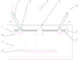
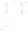
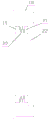
CN109035552B - Smart phone card reader based on block chain technology - Google Patents

Smart phone card reader based on block chain technology Download PDF

Info

Publication number
CN109035552B
CN109035552B CN201811036384.7A CN201811036384A CN109035552B CN 109035552 B CN109035552 B CN 109035552B CN 201811036384 A CN201811036384 A CN 201811036384A CN 109035552 B CN109035552 B CN 109035552B
Authority
CN
China
Prior art keywords
main body
card reader
block chain
smart phone
fixed
Prior art date
Legal status (The legal status is an assumption and is not a legal conclusion. Google has not performed a legal analysis and makes no representation as to the accuracy of the status listed.)
Expired - Fee Related
Application number
CN201811036384.7A
Other languages
Chinese (zh)
Other versions
CN109035552A (en
Inventor
张佳星
张萍
Current Assignee (The listed assignees may be inaccurate. Google has not performed a legal analysis and makes no representation or warranty as to the accuracy of the list.)
Shenzhen Jiuge Innovation Technology Co ltd
Original Assignee
Shenzhen Wanjitong Electronics Co ltd
Priority date (The priority date is an assumption and is not a legal conclusion. Google has not performed a legal analysis and makes no representation as to the accuracy of the date listed.)
Filing date
Publication date
Application filed by Shenzhen Wanjitong Electronics Co ltd filed Critical Shenzhen Wanjitong Electronics Co ltd
Priority to CN201811036384.7A priority Critical patent/CN109035552B/en
Publication of CN109035552A publication Critical patent/CN109035552A/en
Application granted granted Critical
Publication of CN109035552B publication Critical patent/CN109035552B/en
Expired - Fee Related legal-status Critical Current
Anticipated expiration legal-status Critical

Links

Images

Classifications

    • GPHYSICS
    • G07CHECKING-DEVICES
    • G07FCOIN-FREED OR LIKE APPARATUS
    • G07F7/00Mechanisms actuated by objects other than coins to free or to actuate vending, hiring, coin or paper currency dispensing or refunding apparatus
    • G07F7/08Mechanisms actuated by objects other than coins to free or to actuate vending, hiring, coin or paper currency dispensing or refunding apparatus by coded identity card or credit card or other personal identification means
    • G07F7/0873Details of the card reader
    • GPHYSICS
    • G06COMPUTING OR CALCULATING; COUNTING
    • G06QINFORMATION AND COMMUNICATION TECHNOLOGY [ICT] SPECIALLY ADAPTED FOR ADMINISTRATIVE, COMMERCIAL, FINANCIAL, MANAGERIAL OR SUPERVISORY PURPOSES; SYSTEMS OR METHODS SPECIALLY ADAPTED FOR ADMINISTRATIVE, COMMERCIAL, FINANCIAL, MANAGERIAL OR SUPERVISORY PURPOSES, NOT OTHERWISE PROVIDED FOR
    • G06Q20/00Payment architectures, schemes or protocols
    • G06Q20/30Payment architectures, schemes or protocols characterised by the use of specific devices or networks
    • G06Q20/34Payment architectures, schemes or protocols characterised by the use of specific devices or networks using cards, e.g. integrated circuit [IC] cards or magnetic cards
    • G06Q20/341Active cards, i.e. cards including their own processing means, e.g. including an IC or chip
    • G06Q20/3415Cards acting autonomously as pay-media
    • GPHYSICS
    • G06COMPUTING OR CALCULATING; COUNTING
    • G06QINFORMATION AND COMMUNICATION TECHNOLOGY [ICT] SPECIALLY ADAPTED FOR ADMINISTRATIVE, COMMERCIAL, FINANCIAL, MANAGERIAL OR SUPERVISORY PURPOSES; SYSTEMS OR METHODS SPECIALLY ADAPTED FOR ADMINISTRATIVE, COMMERCIAL, FINANCIAL, MANAGERIAL OR SUPERVISORY PURPOSES, NOT OTHERWISE PROVIDED FOR
    • G06Q20/00Payment architectures, schemes or protocols
    • G06Q20/38Payment protocols; Details thereof
    • G06Q20/382Payment protocols; Details thereof insuring higher security of transaction
    • G06Q20/3829Payment protocols; Details thereof insuring higher security of transaction involving key management

Landscapes

  • Business, Economics & Management (AREA)
  • Engineering & Computer Science (AREA)
  • Physics & Mathematics (AREA)
  • Accounting & Taxation (AREA)
  • General Physics & Mathematics (AREA)
  • Strategic Management (AREA)
  • General Business, Economics & Management (AREA)
  • Theoretical Computer Science (AREA)
  • Finance (AREA)
  • Computer Security & Cryptography (AREA)
  • Microelectronics & Electronic Packaging (AREA)
  • Computer Networks & Wireless Communication (AREA)
  • Telephone Set Structure (AREA)

Abstract

The invention relates to a smart phone card reader based on a block chain technology, which comprises a main body and a joint, wherein a processor and a memory are arranged in the main body, a retraction mechanism is arranged in the main body and comprises a driving component and a telescopic component, the telescopic component comprises a telescopic frame, a lifting plate, a fixed block and two hinging blocks, reinforcing mechanisms are respectively arranged at two sides of the main body, each reinforcing mechanism comprises a power box and two reinforcing components, a first motor and two power components are arranged in the power box, the smart phone card reader based on the block chain technology adopts the block chain technology to store data, so that the data safety degree is high, in addition, the smart phone card reader based on the block chain technology can retract the joint into the main body through the retraction mechanism when the smart phone card reader is idle, the probability that the joint is damaged is reduced, and the stability of the connection between the smart phone card reader and a mobile phone can be improved through the reinforcing mechanisms, the phenomenon that the card swiping effect of the mobile phone is influenced by the rotation of the card swiping device is avoided.

Description

Smart phone card reader based on block chain technology
Technical Field
The invention relates to a smart phone card reader based on a block chain technology.
Background
The block chain technology is a brand new distributed infrastructure and a computing mode which utilize a block chain type data structure to verify and store data, utilize a distributed node consensus algorithm to generate and update data, utilize a cryptography mode to ensure the safety of data transmission and access, and utilize an intelligent contract composed of automatic script codes to program and operate data, and is a novel application mode of computer technologies such as distributed data storage, point-to-point transmission, a consensus mechanism, an encryption algorithm and the like.
The data security degree of the block chain technology is high, and the application is very wide. Including a smart phone card reader.
The mobile phone card reader in the prior art generally adopts a traditional data encryption mode, data loss is easily caused, moreover, a connector of the mobile phone card reader in the prior art is exposed outside for a long time, the probability of damage is increased, the safety of the mobile phone card reader is reduced, and moreover, when the mobile phone card reader in the prior art is used for card reading work, the mobile phone card reader is easily driven to rotate, the card reading is influenced, and the stability of connection between the mobile phone card reader and a mobile phone is reduced.
Disclosure of Invention
The technical problem to be solved by the invention is as follows: in order to overcome the defects of the prior art, the smart phone card reader based on the block chain technology is provided.
The technical scheme adopted by the invention for solving the technical problems is as follows: a smart phone card reader based on a block chain technology comprises a main body and a connector, wherein the connector is arranged inside the main body, a processor and a memory are arranged in the main body, the processor is electrically connected with the memory, and the memory receives block chain data written by block chain nodes and stores the block chain data;
a through hole is formed above the main body, a retraction mechanism is arranged in the main body, the joint is arranged on one side of the retraction mechanism, the retraction mechanism comprises a driving assembly and a telescopic assembly, the driving assembly is arranged at the bottom in the main body, and the driving assembly is in transmission connection with the telescopic assembly;
the telescopic assembly comprises a telescopic frame, a lifting plate, a fixed block and two hinge blocks, the fixed block is fixed on one side, close to the joint, of the lifting plate, the joint is fixed on the fixed block, a sliding groove is formed in the lifting plate, one of the two hinge blocks is arranged in the sliding groove, one hinge block is connected with the sliding groove in a sliding mode, the other hinge block is fixed on the lifting plate, two sides of one end of the telescopic frame are respectively hinged with the two hinge blocks, and the other end of the telescopic frame is connected with the driving assembly;
the reinforcing mechanism is arranged on each of two sides of the main body and comprises a power box and two reinforcing assemblies, the power box is fixed on one side of the main body, the two reinforcing assemblies are arranged on two sides above the main body respectively, each reinforcing assembly comprises a supporting shaft and a reinforcing box, the bottom end of each supporting shaft is fixed on the main body, and the supporting shafts are hinged to the reinforcing boxes;
one side of headstock that is close to the joint is equipped with first opening, be equipped with first motor and two power components in the headstock, bottom in the headstock is fixed to first motor, and two power components set up the both sides at first motor respectively, first motor is connected with the power component transmission, first motor is connected with the treater transmission.
Preferably, in order to ensure the safety of the internal facility data of the equipment, a blockchain system is arranged in the processor, the blockchain system comprises a data layer, a network layer, a consensus layer, an incentive layer, a contract layer and an application layer, and the blockchain data is derived from the data layer.
Preferably, in order to improve the intelligence degree of the device, the processor is a PLC, the memory includes a memory database and a disk database, and the memory database and the disk database respectively receive the block chain data written by the block chain node and store the block chain data.
Preferably, for the flexible power that provides for the expansion bracket, drive assembly includes air pump, cylinder and gas pole, air pump and cylinder are all fixed in the bottom of main part, air pump and cylinder intercommunication, the one end setting of gas pole is in the cylinder, the both sides of the bottom of expansion bracket are articulated with the other end and the cylinder of gas pole respectively, the air pump is connected with the treater electricity.
Preferably, in order to limit the moving direction of the lifting plate, the retraction mechanism further comprises two guide rods, the two guide rods are respectively arranged on two sides of the telescopic assembly, the top end and the bottom end of each guide rod are respectively fixed at the top and the bottom in the main body, and two ends of the lifting plate are respectively sleeved in the two guide rods.
Preferably, in order to drive the reinforcing box to overturn, the power assembly comprises a screw rod, a sliding block and a connecting rod, the first motor is in transmission connection with the screw rod, the sliding block is sleeved on the screw rod, a thread matched with the screw rod is arranged at the joint of the sliding block and the screw rod, one end of the connecting rod is hinged to the sliding block, and the other end of the connecting rod is hinged to the reinforcing box.
Preferably, in order to provide a supporting force for the screw rod, the power assembly further comprises a bearing seat, the bearing seat is fixed on the inner wall of one side of the power box, and one end of the screw rod, which is far away from the first motor, is arranged in the bearing seat.
As preferred, for the moving direction of restriction slider, still be equipped with two slides in the headstock, slide and slider one-to-one, the bottom in the headstock is fixed to the slide, the top of slide is equipped with the bar groove, the below of slider sets up in the bar inslot, slider and slide sliding connection.
As preferred, in order to improve the stability that the cell-phone ware of punching the card is connected with the cell-phone, one side of consolidating the box is equipped with the second opening, consolidate the box in and be equipped with reinforced subassembly, reinforced subassembly includes gusset plate and two reinforcement units, and two reinforcement units set up the both ends in one side of gusset plate respectively, reinforced unit includes electro-magnet, spring and iron plate, the electro-magnet is fixed in the one side of consolidating keeping away from the second opening of box, the iron plate is fixed on the inner wall of the one side of keeping away from the second opening of gusset plate, the electro-magnet passes through the spring and is connected with the iron plate, the electro-magnet is connected with the treater electricity.
Preferably, in order to control the operation of the equipment, the main body is provided with a control panel, the control panel is provided with two control keys, and the control keys are electrically connected with the processor.
The smart phone card reader based on the block chain technology has the advantages that the block chain technology is adopted for data storage, so that the data safety degree is high, in addition, the smart phone card reader based on the block chain technology can retract the connector into the main body through the retraction mechanism when the smart phone card reader is idle, and the probability of damage of the connector is reduced.
Drawings
The invention is further illustrated with reference to the following figures and examples.
FIG. 1 is a system diagram of a blockchain system of a smart phone card reader based on blockchain technology in accordance with the present invention;
FIG. 2 is a schematic structural diagram of a smart phone card reader based on the block chain technology according to the present invention;
FIG. 3 is a side view of a smart phone card reader based on blockchain technology of the present invention;
FIG. 4 is a schematic structural diagram of a reinforcing component of a smart phone card reader based on a block chain technology according to the present invention;
FIG. 5 is a schematic structural diagram of a card reader/writer mechanism of a smart phone based on a block chain technology according to the present invention;
in the figure: 1. the main body, 2, a joint, 3, an air pump, 4, an air cylinder, 5, an air rod, 6, a telescopic frame, 7, a hinged block, 8, a lifting plate, 9, a fixed block, 10, a guide rod, 11, a power box, 12, a first motor, 13, a screw rod, 14, a sliding block, 15, a bearing seat, 16, a slide way, 17, a connecting rod, 18, a reinforcing box, 19, an electromagnet, 20, a spring, 21, an iron block, 22, a reinforcing plate and 23, a control panel.
Detailed Description
The present invention will now be described in further detail with reference to the accompanying drawings. These drawings are simplified schematic views illustrating only the basic structure of the present invention in a schematic manner, and thus show only the constitution related to the present invention.
As shown in fig. 1, a smart phone card reader based on a block chain technology includes a main body 1 and a connector 2, the connector 2 is disposed inside the main body 1, a processor and a memory are disposed in the main body 1, the processor is electrically connected to the memory, the memory receives block chain data written by block chain nodes and stores the block chain data, a block chain system is disposed in the processor, the block chain system includes a data layer, a network layer, a common identification layer, an excitation layer, a contract layer and an application layer, the block chain data is derived from the data layer, the processor is a PLC, the memory includes a memory database and a disk database, and the memory database and the disk database respectively receive the block chain data written by the block chain nodes and store the block chain data.
In fact, the processor is mainly used for processing data, and the memory is used for data storage, where:
the data layer encapsulates bottom data blocks and related data encryption, time stamp and other technologies;
in fact, the blockchain data received or stored by the memory database and the disk database are from the data layer.
The network layer comprises a distributed networking mechanism, a data transmission mechanism, a data verification mechanism and the like;
the consensus layer mainly encapsulates various consensus algorithms of the network nodes;
the incentive layer integrates economic factors into a block chain technology system, and mainly comprises an economic incentive issuing mechanism, an economic incentive distributing mechanism and the like;
the contract layer mainly encapsulates various scripts, algorithms and intelligent contracts and is the basis of the programmable characteristic of the block chain;
the application layer encapsulates various application scenarios and cases of the blockchain.
Through the block chain system, the safety of data storage can be guaranteed, and the intelligent degree of equipment is improved.
As shown in fig. 5, a through hole is formed above the main body 1, a retraction mechanism is arranged in the main body 1, the joint 2 is arranged on one side of the retraction mechanism, the retraction mechanism comprises a driving assembly and a telescopic assembly, the driving assembly is arranged at the bottom in the main body 1, and the driving assembly is in transmission connection with the telescopic assembly;
the telescopic assembly comprises a telescopic frame 6, a lifting plate 8, a fixed block 9 and two hinge blocks 7, wherein the fixed block 9 is fixed on one side, close to the joint 2, of the lifting plate 8, the joint 2 is fixed on the fixed block 9, a sliding groove is formed in the lifting plate 8, one hinge block 7 of the two hinge blocks 7 is arranged in the sliding groove, one hinge block 7 is in sliding connection with the sliding groove, the other hinge block 7 is fixed on the lifting plate 8, two sides of one end of the telescopic frame 6 are respectively hinged with the two hinge blocks 7, and the other end of the telescopic frame 6 is connected with the driving assembly;
when the mobile phone card reader is idle, the processor controls the driving assembly to work, so that the expansion bracket 6 contracts, the connector 2 is driven by the lifting plate 8 to be retracted into the main body 1, the probability that the connector 2 is damaged is reduced, and the safety of the mobile phone card reader is improved.
As shown in fig. 2-4, two sides of the main body 1 are respectively provided with a reinforcing mechanism, the reinforcing mechanism comprises a power box 11 and two reinforcing components, the power box 11 is fixed on one side of the main body 1, the two reinforcing components are respectively arranged on two sides above the main body 1, the reinforcing components comprise a supporting shaft and a reinforcing box 18, the bottom end of the supporting shaft is fixed on the main body 1, and the supporting shaft is hinged with the reinforcing box 18;
one side of headstock 11 that is close to joint 2 is equipped with first opening, be equipped with first motor 12 and two power components in the headstock 11, bottom in headstock 11 is fixed to first motor 12, and two power components set up the both sides at first motor 12 respectively, first motor 12 is connected with the power component transmission, first motor 12 is connected with the treater transmission.
When the mobile phone card reader is connected with a mobile phone, the first motor 12 is started, so that the two power assemblies work, the two reinforcing boxes 18 are driven to rotate through the power assemblies, the reinforcing boxes 18 reinforce the mobile phone, the stability of connection between the mobile phone card reader and the mobile phone is improved, and the influence on card reading caused by rotation of the mobile phone card reader is avoided.
Preferably, in order to provide power for the flexible of expansion bracket 6, drive assembly includes air pump 3, cylinder 4 and gas pole 5, the bottom in main part 1 is all fixed to air pump 3 and cylinder 4, air pump 3 and cylinder 4 intercommunication, the one end setting of gas pole 5 is in cylinder 4, the both sides of the bottom of expansion bracket 6 are articulated with the other end and the cylinder 4 of gas pole 5 respectively, air pump 3 is connected with the treater electricity. When the folding and unfolding operation is carried out, the air pump 3 is started, the air rod 5 is driven to move by changing the pressure intensity in the air cylinder 4, the expansion bracket 6 is made to expand and contract, the connector 2 can be driven to be retracted into the main body 1 or pushed out of the main body 1 through the lifting plate 8, and the function of folding and unfolding the connector 2 is achieved.
Preferably, in order to limit the moving direction of the lifting plate 8, the retraction mechanism further includes two guide rods 10, the two guide rods 10 are respectively disposed at two sides of the telescopic assembly, the top end and the bottom end of the guide rods 10 are respectively fixed at the top and the bottom of the main body 1, and two ends of the lifting plate 8 are respectively sleeved in the two guide rods 10. By providing the guide rod 10, the moving direction of the lifting plate 8 is limited, so that the lifting plate 8 is more stable when moving.
Preferably, in order to drive the reinforcing box 18 to turn over, the power assembly comprises a screw rod 13, a sliding block 14 and a connecting rod 17, the first motor 12 is in transmission connection with the screw rod 13, the sliding block 14 is sleeved on the screw rod 13, a thread matched with the screw rod 13 is arranged at the joint of the sliding block 14 and the screw rod 13, one end of the connecting rod 17 is hinged to the sliding block 14, and the other end of the connecting rod 17 is hinged to the reinforcing box 18. The first motor 12 is started, the screw rod 13 rotates to drive the sliding block 14 to move in the direction far away from the first motor 12, and the reinforcing box 18 is driven to rotate through the connecting rod 17, so that the reinforcing box 18 can reinforce the mobile phone, and the stability of the mobile phone card reader connected with the mobile phone is improved.
Preferably, in order to provide a supporting force for the screw 13, the power assembly further comprises a bearing seat 15, the bearing seat 15 is fixed on the inner wall of one side of the power box 11, and one end of the screw 13 far away from the first motor 12 is arranged in the bearing seat 15. Through setting up bearing frame 15, do not influence the pivoted circumstances of lead screw 13, provide the holding power for lead screw 13 is more stable when rotating.
Preferably, in order to limit the moving direction of the sliding block 14, two sliding ways 16 are further arranged in the power box 11, the sliding ways 16 correspond to the sliding blocks 14 one to one, the sliding ways 16 are fixed at the bottom of the power box 11, a strip-shaped groove is formed above the sliding ways 16, the lower portion of the sliding block 14 is arranged in the strip-shaped groove, and the sliding block 14 is connected with the sliding ways 16 in a sliding manner. By arranging the slide way 16, the slide block 14 does not rotate when moving, and the stability of the slide block 14 when moving is improved.
As shown in fig. 4, a second opening is formed in one side of the reinforcing box 18, a reinforcing component is arranged in the reinforcing box 18, the reinforcing component includes a reinforcing plate 22 and two reinforcing units, the two reinforcing units are respectively arranged at two ends of one side of the reinforcing plate 22, the reinforcing unit includes an electromagnet 19, a spring 20 and an iron block 21, the electromagnet 19 is fixed on an inner wall of one side of the reinforcing box 18, which is far away from the second opening, the iron block 21 is fixed on one side of the reinforcing plate 22, which is far away from the second opening, the electromagnet 19 is connected with the iron block 21 through the spring 20, and the electromagnet 19 is electrically connected with the processor. When the reinforcing operation is carried out, the electromagnet 19 is electrified, so that the electromagnet 19 generates a force repulsive to the iron block 21, the reinforcing plate 22 can be pushed out of the reinforcing box 18, the reinforcing operation is carried out, and the stability of connection between the mobile phone card reader and the mobile phone is improved.
Preferably, in order to control the operation of the device, the main body 1 is provided with a control panel 23, and the control panel 23 is provided with two control keys electrically connected with the processor.
When the mobile phone card reader is idle, the processor controls the driving assembly to work, so that the expansion bracket 6 contracts, the connector 2 is driven by the lifting plate 8 to be retracted into the main body 1, the probability that the connector 2 is damaged is reduced, and the safety of the mobile phone card reader is improved. When the mobile phone card reader is connected with a mobile phone, the first motor 12 is started, so that the two power assemblies work, the two reinforcing boxes 18 are driven to rotate through the power assemblies, the reinforcing boxes 18 reinforce the mobile phone, the stability of connection between the mobile phone card reader and the mobile phone is improved, and the influence on card reading caused by rotation of the mobile phone card reader is avoided.
Compared with the prior art, the smart phone card reader based on the block chain technology has the advantages that the block chain technology is adopted for data storage, so that the data safety degree is high, in addition, the smart phone card reader based on the block chain technology can retract the connector 2 into the main body 1 through the retraction mechanism when the smart phone card reader is idle, the probability that the connector 2 is damaged is reduced, compared with the existing retraction mechanism, the retraction mechanism is stable in structure, the safety of the smart phone card reader is improved, the stability of the connection of the smart phone card reader and a mobile phone can be improved through the reinforcing mechanism, the phenomenon that the smart phone card reader rotates to influence the card reading effect is avoided, compared with the existing reinforcing mechanism, the reinforcing mechanism is good in reinforcing effect, and the stability of the smart phone card reader is improved.
In light of the foregoing description of the preferred embodiment of the present invention, many modifications and variations will be apparent to those skilled in the art without departing from the spirit and scope of the invention. The technical scope of the present invention is not limited to the content of the specification, and must be determined according to the scope of the claims.

Claims (9)

1. A smart phone card reader based on a block chain technology comprises a main body (1) and a connector (2), wherein the connector (2) is arranged inside the main body (1), and is characterized in that a processor and a memory are arranged in the main body (1), the processor is electrically connected with the memory, and the memory receives block chain data written by a block chain node and stores the block chain data;
a through hole is formed above the main body (1), a retraction mechanism is arranged in the main body (1), the joint (2) is arranged on one side of the retraction mechanism, the retraction mechanism comprises a driving assembly and a telescopic assembly, the driving assembly is arranged at the bottom in the main body (1), and the driving assembly is in transmission connection with the telescopic assembly;
the telescopic assembly comprises a telescopic frame (6), a lifting plate (8), a fixed block (9) and two hinged blocks (7), wherein the fixed block (9) is fixed on one side, close to the joint (2), of the lifting plate (8), the joint (2) is fixed on the fixed block (9), a sliding groove is formed in the lifting plate (8), one of the hinged blocks (7) is arranged in the sliding groove, one of the hinged blocks (7) is in sliding connection with the sliding groove, the other hinged block (7) is fixed on the lifting plate (8), two sides of one end of the telescopic frame (6) are respectively hinged to the two hinged blocks (7), and the other end of the telescopic frame (6) is connected with a driving assembly;
the reinforcing mechanism is arranged on each of two sides of the main body (1) and comprises a power box (11) and two reinforcing assemblies, the power box (11) is fixed on one side of the main body (1), the two reinforcing assemblies are arranged on two sides above the main body (1) respectively, each reinforcing assembly comprises a supporting shaft and a reinforcing box (18), the bottom end of each supporting shaft is fixed on the main body (1), and each supporting shaft is hinged to the corresponding reinforcing box (18);
a first opening is formed in one side, close to the joint (2), of the power box (11), a first motor (12) and two power assemblies are arranged in the power box (11), the first motor (12) is fixed to the bottom in the power box (11), the two power assemblies are respectively arranged on two sides of the first motor (12), the first motor (12) is in transmission connection with the power assemblies, and the first motor (12) is in transmission connection with the processor;
one side of consolidating box (18) is equipped with the second opening, be equipped with the reinforcement subassembly in consolidating box (18), the reinforcement subassembly includes gusset plate (22) and two reinforcement units, and two reinforcement units set up the both ends in one side of gusset plate (22) respectively, the reinforcement unit includes electro-magnet (19), spring (20) and iron plate (21), electro-magnet (19) are fixed on the inner wall of the second open-ended one side of keeping away from of consolidating box (18), second open-ended one side of keeping away from of gusset plate (22) is fixed in iron plate (21), electro-magnet (19) are connected with iron plate (21) through spring (20), electro-magnet (19) are connected with the treater electricity.
2. The smart phone card reader based on the blockchain technology as claimed in claim 1, wherein a blockchain system is arranged in the processor, the blockchain system comprises a data layer, a network layer, a consensus layer, a stimulus layer, a contract layer and an application layer, and the blockchain data is derived from the data layer.
3. The smart phone card reader based on the blockchain technology as claimed in claim 1, wherein the processor is a single chip or a PLC, the memory includes a memory database and a disk database, and the memory database and the disk database respectively receive blockchain data written by blockchain nodes and store the blockchain data.
4. The smart phone card reader based on the block chain technology as claimed in claim 1, wherein the driving assembly comprises an air pump (3), an air cylinder (4) and an air rod (5), the air pump (3) and the air cylinder (4) are both fixed at the bottom of the main body (1), the air pump (3) is communicated with the air cylinder (4), one end of the air rod (5) is arranged in the air cylinder (4), two sides of the bottom end of the telescopic frame (6) are respectively hinged with the other end of the air rod (5) and the air cylinder (4), and the air pump (3) is electrically connected with the processor.
5. A smart phone card reader based on block chain technology as claimed in claim 1, wherein the retracting mechanism further comprises two guiding rods (10), the two guiding rods (10) are respectively disposed at two sides of the telescopic assembly, the top end and the bottom end of the guiding rods (10) are respectively fixed at the top and the bottom of the main body (1), two ends of the lifting plate (8) are respectively sleeved in the two guiding rods (10), and the lifting plate (8) is slidably connected with the guiding rods (10).
6. A smart phone card reader based on block chain technology as claimed in claim 1, wherein the power assembly comprises a screw rod (13), a slider (14) and a connecting rod (17), the first motor (12) is in transmission connection with the screw rod (13), the slider (14) is sleeved on the screw rod (13), a connecting part of the slider (14) and the screw rod (13) is provided with a thread matching with the screw rod (13), one end of the connecting rod (17) is hinged with the slider (14), and the other end of the connecting rod (17) is hinged with the reinforcing box (18).
7. A smart phone card reader based on block chain technology according to claim 6, wherein the power assembly further comprises a bearing seat (15), the bearing seat (15) is fixed on the inner wall of one side of the power box (11), and one end of the screw rod (13) far away from the first motor (12) is arranged in the bearing seat (15).
8. The smart phone card reader based on the block chain technology as claimed in claim 6, wherein two slide ways (16) are further arranged in the power box (11), the slide ways (16) are in one-to-one correspondence with the slide blocks (14), the slide ways (16) are fixed at the bottom in the power box (11), a strip-shaped groove is formed above the slide ways (16), the lower part of the slide block (14) is arranged in the strip-shaped groove, and the slide blocks (14) are slidably connected with the slide ways (16).
9. A smart phone card reader based on block chain technology as claimed in claim 1, wherein the main body (1) is provided with a control panel (29), the control panel (29) is provided with two control keys, and the control keys are electrically connected with the processor.
CN201811036384.7A 2018-09-06 2018-09-06 Smart phone card reader based on block chain technology Expired - Fee Related CN109035552B (en)

Priority Applications (1)

Application Number Priority Date Filing Date Title
CN201811036384.7A CN109035552B (en) 2018-09-06 2018-09-06 Smart phone card reader based on block chain technology

Applications Claiming Priority (1)

Application Number Priority Date Filing Date Title
CN201811036384.7A CN109035552B (en) 2018-09-06 2018-09-06 Smart phone card reader based on block chain technology

Publications (2)

Publication Number Publication Date
CN109035552A CN109035552A (en) 2018-12-18
CN109035552B true CN109035552B (en) 2021-10-15

Family

ID=64624333

Family Applications (1)

Application Number Title Priority Date Filing Date
CN201811036384.7A Expired - Fee Related CN109035552B (en) 2018-09-06 2018-09-06 Smart phone card reader based on block chain technology

Country Status (1)

Country Link
CN (1) CN109035552B (en)

Families Citing this family (4)

* Cited by examiner, † Cited by third party
Publication number Priority date Publication date Assignee Title
CN109215215B (en) * 2018-09-06 2019-12-24 深圳中琛源科技股份有限公司 A mobile phone credit card reader with storage function based on blockchain technology
CN109830074A (en) * 2019-01-28 2019-05-31 深圳市中科智诚科技有限公司 A kind of mobile phone card reader convenient for storage based on block chain technology
CN109961524B (en) * 2019-03-14 2021-10-22 深圳市星宏辉科技有限公司 Convenient card swiping device based on block chain technology and used for public transportation system
CN110164065B (en) * 2019-05-07 2021-06-25 深圳慧卡科技有限公司 Mobile POS machine with good contact for payment transaction

Citations (4)

* Cited by examiner, † Cited by third party
Publication number Priority date Publication date Assignee Title
CN2705830Y (en) * 2004-05-31 2005-06-22 林宣满 Self-aid bank card scanner
CN106446067A (en) * 2016-09-06 2017-02-22 联动优势科技有限公司 Transaction data acquisition method and apparatus
CN107122477A (en) * 2017-05-02 2017-09-01 成都中远信电子科技有限公司 A kind of block chain storage system
CN108416950A (en) * 2018-03-01 2018-08-17 深圳市安思科电子科技有限公司 A kind of steady type cell phone card reader with connection-peg defencive function

Family Cites Families (14)

* Cited by examiner, † Cited by third party
Publication number Priority date Publication date Assignee Title
DE19720527A1 (en) * 1997-05-16 1998-11-19 Peter Fuchs Supermarket trolley return system
KR100447431B1 (en) * 2004-03-15 2004-09-07 (주)엠씨페이 a wireless credit card settle accounting apparatus
DE102010038179B4 (en) * 2010-10-14 2013-10-24 Kobil Systems Gmbh Individual updating of computer programs
US20120234918A1 (en) * 2011-03-16 2012-09-20 Lindsay Peter R Card reader device for a cell phone and method of use
CN202486891U (en) * 2011-12-31 2012-10-10 智嘉通讯科技(东莞)有限公司 New card reader
KR101343015B1 (en) * 2012-06-19 2013-12-18 주식회사 제패트로닉스 Hybrid card reader for smart phone
CN103035066A (en) * 2012-12-14 2013-04-10 广州市易票联支付技术有限公司 Mobile phone card reader with positioning element
CN203466350U (en) * 2013-07-17 2014-03-05 深圳华智融科技股份有限公司 Plug expansion and contraction device
US9208487B2 (en) * 2013-09-03 2015-12-08 Smart Approach Co., Ltd. Card transaction device and method thereof
US8910868B1 (en) * 2013-11-27 2014-12-16 Square, Inc. Firmware management
CN205121743U (en) * 2015-07-28 2016-03-30 王绍峰 External ware of punching card of internet finance cell -phone
CN105877363B (en) * 2016-02-15 2017-06-20 郭浣华 A kind of cup lid and the cup using the cup lid
CN206427895U (en) * 2017-01-20 2017-08-22 广东长城电梯有限公司 A kind of magnetic mutually repelling safety elevator
CN206480078U (en) * 2017-02-28 2017-09-08 唐山市君浩科技有限公司 A kind of financial mobile phone external card reader in internet

Patent Citations (4)

* Cited by examiner, † Cited by third party
Publication number Priority date Publication date Assignee Title
CN2705830Y (en) * 2004-05-31 2005-06-22 林宣满 Self-aid bank card scanner
CN106446067A (en) * 2016-09-06 2017-02-22 联动优势科技有限公司 Transaction data acquisition method and apparatus
CN107122477A (en) * 2017-05-02 2017-09-01 成都中远信电子科技有限公司 A kind of block chain storage system
CN108416950A (en) * 2018-03-01 2018-08-17 深圳市安思科电子科技有限公司 A kind of steady type cell phone card reader with connection-peg defencive function

Also Published As

Publication number Publication date
CN109035552A (en) 2018-12-18

Similar Documents

Publication Publication Date Title
CN109035552B (en) Smart phone card reader based on block chain technology
CN103914324B (en) A kind of method and its system of automatic programming embedded device firmware
CN107977217A (en) The method of on-line loaded XILINX-FPGA multi versions more new procedures
CN102662913A (en) Method and MCU (microcontroller unit) chip for improving storage performance of MCU
CN109033916B (en) Code scanner based on block chain technology
CN104751206A (en) Cabinet based on UHF (Ultra High Frequency) electronic tag and article information reading method therein
CN101706860B (en) Card reader and intelligent card
CN101702119B (en) Device oriented programming technology and method
CN100583293C (en) Storage device and read-write method thereof
CN102708075A (en) Secure digital (SD) memory card hardware control device and control method
CN207489166U (en) It is a kind of to scan the two-dimensional code the intelligent public bookcase for opening cabinet door
CN107622027A (en) A kind of All-in-One Flash controllers and fabrication method
CN204965624U (en) Self -service library's book case of borrowing book
CN210864372U (en) Intelligent control type electric meter box
CN1265749A (en) Circuit configuration and method of storage management and application of user program in small control units
CN109003406B (en) Block chain technology-based mobile POS machine with moisture-proof function
CN109409149A (en) A kind of scanning based on block chain technology accurately mobile phone code reader
CN104503369A (en) Servo driver and servo parameter operation method
CN206233724U (en) The electromagnetism lock control system and intelligent cabinet of intelligent cabinet
CN106228154A (en) Supercargo's identity authorization system based on escort delivery identification electronic Verification System
CN109215261A (en) A kind of smart phone card reader of the antisitic defect based on block chain technology
CN202453910U (en) Card pre-issuing device
CN214122861U (en) Copyright asset management device for big data processing
KR102727710B1 (en) Management support management system
CN112278678A (en) A vehicle body moving device

Legal Events

Date Code Title Description
PB01 Publication
PB01 Publication
SE01 Entry into force of request for substantive examination
CB03 Change of inventor or designer information

Inventor after: Zhang Jiaxing

Inventor after: Zhang Ping

Inventor before: Zhang Ping

CB03 Change of inventor or designer information
TA01 Transfer of patent application right

Effective date of registration: 20210924

Address after: 518000 floor 3, building a, No. 5, Minle Road, Pinghu community, Pinghu street, Longgang District, Shenzhen, Guangdong Province (i.e. floor 3, building 7, Fumin Industrial Zone)

Applicant after: Shenzhen wanjitong Electronics Co.,Ltd.

Address before: 518000 A, unit 12, phase four, Keyuan four, bu Sha Road, Longgang District, Shenzhen, Guangdong.

Applicant before: Zhang Ping

GR01 Patent grant
GR01 Patent grant
TR01 Transfer of patent right

Effective date of registration: 20240614

Address after: Room 602A, Building B, Zhongshen Garden, No. 2010 Caitian Road, Fushan Community, Futian Street, Futian District, Shenzhen City, Guangdong Province, 518035

Patentee after: Shenzhen Jiuge Innovation Technology Co.,Ltd.

Country or region after: China

Address before: 518000 floor 3, building a, No. 5, Minle Road, Pinghu community, Pinghu street, Longgang District, Shenzhen, Guangdong Province (i.e. floor 3, building 7, Fumin Industrial Zone)

Patentee before: Shenzhen wanjitong Electronics Co.,Ltd.

Country or region before: China

TR01 Transfer of patent right
CF01 Termination of patent right due to non-payment of annual fee

Granted publication date: 20211015

CF01 Termination of patent right due to non-payment of annual fee