CN108945552B - Automatic resistance reducing agent adding device - Google Patents
Automatic resistance reducing agent adding device Download PDFInfo
- Publication number
- CN108945552B CN108945552B CN201810517784.3A CN201810517784A CN108945552B CN 108945552 B CN108945552 B CN 108945552B CN 201810517784 A CN201810517784 A CN 201810517784A CN 108945552 B CN108945552 B CN 108945552B
- Authority
- CN
- China
- Prior art keywords
- soil
- unit
- resistance value
- spline
- reducing agent
- Prior art date
- Legal status (The legal status is an assumption and is not a legal conclusion. Google has not performed a legal analysis and makes no representation as to the accuracy of the status listed.)
- Active
Links
- 239000003638 chemical reducing agent Substances 0.000 title claims abstract description 37
- 239000002689 soil Substances 0.000 claims abstract description 61
- 238000001514 detection method Methods 0.000 claims abstract description 42
- XLYOFNOQVPJJNP-UHFFFAOYSA-N water Substances O XLYOFNOQVPJJNP-UHFFFAOYSA-N 0.000 claims abstract description 29
- 230000003321 amplification Effects 0.000 claims abstract description 3
- 238000003199 nucleic acid amplification method Methods 0.000 claims abstract description 3
- 230000003020 moisturizing effect Effects 0.000 claims description 15
- 238000007569 slipcasting Methods 0.000 claims description 10
- 238000005553 drilling Methods 0.000 claims description 6
- 239000007787 solid Substances 0.000 claims 2
- 239000002699 waste material Substances 0.000 abstract description 5
- 239000000463 material Substances 0.000 abstract description 4
- 238000001035 drying Methods 0.000 abstract description 3
- 238000010586 diagram Methods 0.000 description 5
- 150000002500 ions Chemical class 0.000 description 4
- 238000009736 wetting Methods 0.000 description 4
- 238000000034 method Methods 0.000 description 2
- NRTLIYOWLVMQBO-UHFFFAOYSA-N 5-chloro-1,3-dimethyl-N-(1,1,3-trimethyl-1,3-dihydro-2-benzofuran-4-yl)pyrazole-4-carboxamide Chemical compound C=12C(C)OC(C)(C)C2=CC=CC=1NC(=O)C=1C(C)=NN(C)C=1Cl NRTLIYOWLVMQBO-UHFFFAOYSA-N 0.000 description 1
- 230000009286 beneficial effect Effects 0.000 description 1
- 230000000903 blocking effect Effects 0.000 description 1
- 239000004020 conductor Substances 0.000 description 1
- 230000007547 defect Effects 0.000 description 1
- 238000009792 diffusion process Methods 0.000 description 1
- 230000000694 effects Effects 0.000 description 1
- 230000005611 electricity Effects 0.000 description 1
- 238000007689 inspection Methods 0.000 description 1
- 230000013011 mating Effects 0.000 description 1
- 238000012986 modification Methods 0.000 description 1
- 230000004048 modification Effects 0.000 description 1
- 230000000284 resting effect Effects 0.000 description 1
Images


Classifications
-
- B—PERFORMING OPERATIONS; TRANSPORTING
- B65—CONVEYING; PACKING; STORING; HANDLING THIN OR FILAMENTARY MATERIAL
- B65B—MACHINES, APPARATUS OR DEVICES FOR, OR METHODS OF, PACKAGING ARTICLES OR MATERIALS; UNPACKING
- B65B3/00—Packaging plastic material, semiliquids, liquids or mixed solids and liquids, in individual containers or receptacles, e.g. bags, sacks, boxes, cartons, cans, or jars
- B65B3/26—Methods or devices for controlling the quantity of the material fed or filled
-
- G—PHYSICS
- G01—MEASURING; TESTING
- G01N—INVESTIGATING OR ANALYSING MATERIALS BY DETERMINING THEIR CHEMICAL OR PHYSICAL PROPERTIES
- G01N27/00—Investigating or analysing materials by the use of electric, electrochemical, or magnetic means
- G01N27/02—Investigating or analysing materials by the use of electric, electrochemical, or magnetic means by investigating impedance
- G01N27/04—Investigating or analysing materials by the use of electric, electrochemical, or magnetic means by investigating impedance by investigating resistance
- G01N27/045—Circuits
Landscapes
- Chemical & Material Sciences (AREA)
- Health & Medical Sciences (AREA)
- Analytical Chemistry (AREA)
- Chemical Kinetics & Catalysis (AREA)
- Electrochemistry (AREA)
- Physics & Mathematics (AREA)
- Engineering & Computer Science (AREA)
- Life Sciences & Earth Sciences (AREA)
- Mechanical Engineering (AREA)
- Biochemistry (AREA)
- General Health & Medical Sciences (AREA)
- General Physics & Mathematics (AREA)
- Immunology (AREA)
- Pathology (AREA)
- Investigating Or Analyzing Materials By The Use Of Electric Means (AREA)
Abstract
The invention discloses an automatic resistance reducing agent adding device, which relates to the field of grounding electrode detection, and adopts the technical scheme that the device comprises a placing disc, a grouting pipe, a material storage tank and a grouting valve, wherein the placing disc, the grouting pipe, the material storage tank and the grouting valve are arranged on a grounding electrode, the bottom end of the grouting pipe is clamped with the grounding electrode, a resistance value detection module is arranged on the grounding electrode, and the resistance value detection module comprises: the resistance value detection unit, the first amplification unit and the alarm unit. When the resistance value of the soil is increased, the first comparison unit outputs a high level signal to drive the alarm unit to work, water needs to be added into the soil to avoid the increase of the soil resistance value due to sudden drying, if the alarm unit continues to work after the water is added into the soil, the resistance reducing agent in the soil needs to be added into the soil if the resistance reducing agent in the soil is too little, the grouting valve is opened at the moment, the resistance reducing agent is added into the grounding electrode until the alarm unit stops working, the resistance reducing agent is added into the soil only when the resistance reducing agent in the soil is too little, and the waste of the resistance reducing agent is avoided.
Description
Technical Field
The invention relates to the field of grounding electrode detection, in particular to an automatic resistance reducing agent adding device.
Background
The grounding electrode is used as a conductor which is in close contact with the soil of the ground and provides an electrical connection with the ground, and the energy of the safe free flow thunder is discharged into the ground. The resistance reducing agent is used as an auxiliary material for reducing the resistance of the soil around the grounding electrode. The resistance reducing agent is generally added to the inside of the ground electrode, and is slowly diffused in the soil through the holes formed in the ground electrode, and the resistance of the surrounding soil is reduced by the ions ionized from the resistance reducing agent. The resistance reducing agent in the grounding electrode is gradually reduced along with the diffusion of ions, and when the resistance reducing agent in the grounding electrode is used up, the resistance of the surrounding soil is increased due to the lack of ions.
Since the earth electrode is buried in the soil layer, which affects not only the amount of ionizable ions in the soil but also the moisture of the soil, when the resistance value of the soil increases, it cannot be determined whether the cause of the increase in the resistance value of the soil is affected by the resistance reducer. The resistance of the soil is increased due to the drying of the soil, and at the moment, the resistance of the soil cannot be improved by adding the resistance reducing agent into the grounding electrode, so that the waste of the resistance reducing agent is caused.
Disclosure of Invention
Aiming at the defects in the prior art, the invention aims to provide an automatic resistance reducing agent adding device capable of reducing waste of the resistance reducing agent.
In order to achieve the purpose, the invention provides the following technical scheme: the utility model provides an automatic device that adds of resistance reducing agent, is placing the slip casting pipe on the dish, setting up the slip casting pipe on placing the dish, setting up the storage tank in slip casting pipe top and fixing the slip casting valve on slip casting pipe top and lie in the storage tank bottom including setting up on the earthing pole, the bottom of slip casting pipe is provided with resistance detection module on with earthing pole joint earthing pole, resistance detection module includes: the resistance detection unit comprises a resistance detector fixed on the grounding electrode, and the resistance detector detects the resistance condition of the soil in real time and outputs a current signal; the first comparison unit is coupled with the resistance value detection unit, compares a current signal output by the resistance value detection unit with a preset reference value, and outputs a high level signal when the current signal is greater than the preset reference value; the first amplifying unit is coupled with the first comparing unit and amplifies and outputs the high-level signal output by the first comparing unit; and the alarm unit receives the electric signal output by the first amplification unit and outputs an alarm signal.
By adopting the technical scheme, when the resistance value of the soil is increased, the first comparison unit outputs a high level signal to drive the alarm unit to work, in order to avoid the increase of the soil resistance value caused by sudden drying, water needs to be added into the soil, if the alarm unit continues to work after the water is added into the soil, the resistance reducing agent in the soil needs to be reduced, at the moment, the grouting valve is opened, the resistance reducing agent is added into the grounding electrode, the alarm unit stops working, the resistance reducing agent is added into the soil only when the resistance reducing agent in the soil is too small, and the waste of the resistance reducing agent is avoided.
The invention is further configured to: a moisturizing device is arranged on one side of the grouting pipe, and a fixing block is rotatably connected to the grouting pipe; the moisturizing device comprises a connecting block fixedly connected with the fixing block, a motor arranged on the connecting block, a spline housing driven by the motor to rotate and rotationally connected with the connecting block, a spline shaft matched with the spline housing, a rotating head fixed at the bottom end of the spline shaft and a water delivery pipe inserted in the spline housing and the spline shaft; a main gear is fixed on an output shaft of the motor, wall teeth matched with the main gear are arranged at the top end of the spline housing, a spline groove is formed in the spline housing, the spline shaft is hollow, a spline matched with the spline groove is arranged outside the spline shaft, and a plurality of water outlet holes are formed in the bottom end of the spline shaft; still be provided with the drive circuit of control moisturizing device work on the device of moisturizing, drive circuit includes: the forward rotation control module controls the motor to rotate forward to drive the rotating head and the spline shaft to drill into soil; the driving module drives the motor to rotate and drives the spline shaft and the rotating head to rotate; the reverse control module controls the motor to rotate reversely to drive the rotating head and the spline shaft to leave the soil; and the humidity detection module is used for detecting the humidity condition in the soil in real time, and controlling the reverse rotation control module to work and the reverse rotation of the motor when the humidity in the soil is qualified.
Through adopting above-mentioned technical scheme, alarm unit work back, corotation control module work drives the integral key shaft and gets into the inside of soil, and later humidity detection module work, if the humidity of soil is low then the integral key shaft does not return, leads to water in the water delivery pipe this moment, and after the humidity of soil reachd the requirement, the motor reversal drives the integral key shaft and returns, makes things convenient for the resistance of automated inspection soil and leads to water in to soil.
The invention is further configured to: the alarm unit comprises a buzzer HD connected in series in the circuit.
By adopting the technical scheme, the alarm unit works, the buzzer works, and the increase of the soil resistance value is conveniently informed.
The invention is further configured to: the placing disc is provided with a plurality of water through holes, and the water through holes are distributed in a circumferential array by taking the circle center of the placing disc as the circle center.
By adopting the technical scheme, the circumference array of the limbers can uniformly wet the periphery of the grounding electrode, and the wetting effect is improved.
The invention is further configured to: the placing disc is provided with an annular groove with the radius smaller than the distance from the water through holes to the circle center of the placing disc, a clamping ring is arranged in the annular groove, and the clamping ring is provided with open grooves with the same number as the water through holes; the bottom mounting of fixed block has fixed cover and rotates the L shape screens pole of being connected with the slip casting pipe, and the bottom and the screens ring butt of screens pole have still cup jointed the spring on the slip casting pipe, and the spring setting is between screens pole and fixed cover.
Through adopting above-mentioned technical scheme, the quantity of open slot is the same with the quantity of limbers, and the screens pole rotates the position to the open slot at every turn, and the wetting device moves the top of limbers, conveniently rotates the wetting device, makes the wetting device can both align the limbers at every turn.
The invention is further configured to: the placing plate is provided with a plurality of through holes, fixing devices are arranged in the through holes, and each fixing device comprises a fixing ring fixedly connected with the through holes and a sliding rod slidably connected with the fixing ring.
Through adopting above-mentioned technical scheme, through the slide bar that inserts in soil, it is convenient to fix placing the dish.
The invention is further configured to: the bottom end of the sliding rod is fixed with a ground drilling head.
Through adopting above-mentioned technical scheme, bore the ground head and further make things convenient for the slide bar to insert in the soil.
The invention is further configured to: the bottom mounting of through-hole has fixed cover, sliding connection has the mounting on the fixed cover, the inboard of mounting is provided with the inclined plane, be provided with on the slide bar with slide bar complex back taper.
Through adopting above-mentioned technical scheme, press the slide bar downwards, make the mounting stretch out the outside of fixed cover, increase the area with soil contact, further improve and place the fixed stability of dish.
The invention is further configured to: the rotary head is provided with an earth drilling thread.
Through adopting above-mentioned technical scheme, bore the more convenient rotatory rotating head of ground screw and get into soil.
In conclusion, the invention has the following beneficial effects: the invention detects the soil humidity first, and reduces the waste of the resistance reducing agent by placing the situation that the soil resistance value is increased due to the dry soil.
Drawings
FIG. 1 is an overall isometric view of an embodiment;
FIG. 2 is an isometric view of a resting tray;
FIG. 3 is an isometric view of the turning gear;
FIG. 4 is an isometric view of the fixation device;
FIG. 5 is a cross-sectional view of the fixture;
FIG. 6 is an enlarged view of portion A of FIG. 5;
fig. 7 is an isometric view of a moisturizing device;
FIG. 8 is a schematic view showing the mating of spline grooves with spline shafts;
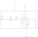
FIG. 9 is a circuit diagram of a resistance detection module;
FIG. 10 is a circuit diagram of a forward rotation control module;
FIG. 11 is a circuit diagram of a driver module;
FIG. 12 is a circuit diagram of an inversion control module;
FIG. 13 is a circuit diagram of a humidity detection module.
In the figure: 1. a ground electrode; 2. placing a tray; 21. a through hole; 22. a water through hole; 23. an annular groove; 24. a position clamping ring; 241. an open slot; 3. a fixing device; 31. a fixing ring; 32. a slide bar; 321. back tapering; 33. a fixing member; 331. a bevel; 332. a protrusion; 34. fixing a sleeve; 341. a groove; 35. drilling a ground head; 4. a rotating device; 41. a grouting pipe; 42. a position clamping rod; 421. a spring; 43. a fixed block; 431. fixing a sleeve; 44. a material storage tank; 45. a grouting valve; 46. a travel switch; 5. a moisturizing device; 51. connecting blocks; 52. a motor; 521. a main gear; 53. wall teeth; 54. a spline housing; 541. a spline groove; 55. a spline shaft; 551. a spline; 552. a water outlet hole; 56. rotating the head; 561. drilling ground threads; 57. a water delivery pipe; 6. a resistance value detection module; 61. a resistance value detection unit; 62. a first comparing unit; 63. a first amplifying unit; 64. an alarm unit; 7. a forward rotation control module; 71. a forward rotation control unit; 72. a forward rotation stopping unit; 8. a drive module; 81. a forward rotation drive unit; 82. a reverse drive unit; 83. a reverse rotation control unit; 9. a reverse rotation control module; 10. a humidity detection module; 101. a humidity detection unit; 102. a second detection unit; 103. a second amplifying unit; 104. and an output unit.
Detailed Description
The present invention will be described in further detail with reference to the accompanying drawings.
Example (b): an automatic resistance reducing agent adding device is shown in fig. 1 and comprises a placing disc 2 arranged above a grounding electrode 1, a fixing device 3 fixed on the placing disc 2, a rotating device 4 rotatably connected to the circle center of the placing disc 2 and a moisturizing device 5 arranged on one side of the rotating device 4.
Referring to fig. 2, a plurality of through holes 21 are formed in the placing disc 2, the through holes 21 are arranged in a circumferential array with the circle center of the placing disc 2 as the circle center, and the fixing device 3 is fixedly connected with the placing disc 2 through the through holes 21. The placing disc 2 is also provided with water through holes 22 which are circumferentially arrayed by taking the circle center of the placing disc 2 as the circle center. The placing disc 2 is provided with an annular groove 23, and the radius of the annular groove 23 is smaller than the distance from the limber hole 22 to the circle center of the placing disc 2. The annular groove 23 is fixed with a retaining ring 24, and the retaining ring 24 is circumferentially provided with open grooves 241 with the same number as the water through holes 22.
Referring to fig. 3, the rotating device 4 includes a grouting pipe 41 rotatably connected to the center of the placing tray 2, an L-shaped clamping rod 42 rotatably connected to the grouting pipe 41, a fixing block 43 rotatably connected to the periphery of the grouting pipe 41, a storage tank 44 fixed to the top end of the grouting pipe 41, and a grouting valve 45 disposed between the storage tank 44 and the grouting pipe 41. The bottom end of the grouting pipe 41 is clamped with the grounding electrode 1. The bottom end of the position clamping rod 42 is abutted against the position clamping ring (24). The bottom end of the fixed block 43 is fixed with a fixed sleeve 431 sleeved on the grouting pipe 41. The grouting pipe 41 is further sleeved with a spring 421, and the spring 421 is arranged between the fixing sleeve 431 and the blocking rod 42. The side of the water passage hole 22 is provided with a travel switch 46.
Referring to fig. 4 and 5, the fixing device 3 includes a fixing ring 31 fixed on the through hole 21, a sliding rod 32 slidably connected with the fixing ring 31, a fixing member 33 fixed on the sliding rod 32, a fixing sleeve 34 fixed at the bottom end of the placing plate 2 (see fig. 1), and a ground drilling head 35 fixed on the periphery of the fixing sleeve 34.
Referring to fig. 6, an inverted cone 321 is disposed at the connection position of the sliding rod 32 and the fixed member 33, and the connection surface of the fixed member 33 and the sliding rod 32 is an inclined surface 331 engaged with the inverted cone 321. The fixing sleeve 34 has a groove 341 formed therein, and the fixing member 33 has a protrusion 332 slidably fitted in the groove 341.
Referring to fig. 7 and 8, the moisturizing device 5 includes a connecting block 51 fixedly connected to the fixing block 43 (see fig. 3), a motor 52 disposed on the connecting block 51, a spline housing 54 driven by the motor 52 to rotate, a spline shaft 55 slidably connected to the spline housing 54, a rotating head 56 fixed to a bottom end of the spline shaft 55, and a water pipe 57 inserted into the spline shaft 55.
The output shaft of the motor 52 is fixed with a main gear 521, and the outer part of the spline housing 54 is provided with wall teeth 53 matched with the main gear 521. Spline groove 541 is formed in spline housing 54, spline 551 matched with spline groove 541 is fixed outside spline shaft 55, spline shaft 55 is hollow, and a plurality of water outlet holes 552 are formed in the bottom end of spline shaft 55. The rotating head 56 is provided with earth-boring threads 561.
The moisturizing device 5 is provided with a driving circuit for controlling the movement of the moisturizing device 5, and the driving circuit comprises a forward rotation control module 7, a driving module 8, a reverse rotation control module 9 and a humidity detection module 10.
And a resistance value detection module 6 is arranged on the grounding electrode 1. Referring to fig. 9, the resistance value detection module 6 includes a resistance value detection unit 61 coupled to the power source VCC, the resistance value detection unit 61 includes a resistance value detector disposed on the ground electrode 1, the resistance value detector detects resistance value information of the soil in real time and outputs a current value signal, and when the soil resistance value is high, the output current value signal is large; the resistance value detection unit 61 is coupled to the first comparison unit 62, the first comparison unit 62 includes a first comparator T1, a positive input terminal of the first comparator T1 receives the current value signal output by the resistance value detection unit, a negative input terminal of the first comparator T3526 inputs a first preset value Vref1, and when the signal of the positive input terminal is greater than the signal of the negative input terminal, a high level signal is output; a first amplifying unit 63, an output terminal of the first comparator T1 is coupled to a positive input terminal of the first amplifier T2, a resistor R6 is coupled between a negative input terminal and an output terminal of the first amplifier T2, a resistor R7 is further coupled to a negative input terminal of the first amplifier T2, and the first amplifying unit is grounded via a resistor R6; the alarm unit 64, the alarm unit 64 includes a buzzer HA coupled to the output terminal of the amplifier T2, a resistor R8 connected in series with the buzzer HA, and a resistor R8 coupled to the resistor R7 and then grounded.
Referring to fig. 10, the forward rotation control module 7 includes a first stroke switch SB1 coupled to the power source VCC, a resistor R connected in series with the first stroke switch SB1, a forward rotation control unit 71 coupled to the resistor R1, and a forward rotation stopping unit 72 connected in parallel to the forward rotation control unit 71, and the forward rotation control unit 71 is grounded after being coupled to the forward rotation stopping unit. The forward rotation control unit 71 includes a first electromagnetic coil KA1 connected in series in an electric circuit, and the forward rotation stopping unit 72 includes a normally open contact KA 3-1.
Referring to FIG. 11, the normally open contact KA1-1 is coupled to the power source VCC, and the driver module 8 is coupled to the normally open contact KA 1-1. The driving module 8 comprises a forward rotation driving unit 81, wherein the forward rotation driving unit 81 comprises a motor M (equal to the motor 52 in FIG. 7) coupled with a normally open contact KA1-1, and normally closed contacts KA2-1 coupled at two ends of the motor M; the reverse driving unit 82 is characterized in that the reverse driving unit 82 comprises a normally open contact KA2-1 which is connected in parallel at two ends of a circuit where the motor M and any one normally closed contact KA2-1 which is arranged in series are located; and a reverse rotation control unit 83, wherein the reverse rotation control unit 83 comprises a normally open contact KA5-1 which is connected with the normally open contact KA1-1 in parallel.
Referring to fig. 12, the reverse rotation control module 9 includes a second stroke switch SB2 in series with the power source VCC, a resistor R2 in series with the second stroke switch SB2, a third solenoid KA3 in series with the resistor R2, and a fourth solenoid KA4 in series with the third solenoid KA3, the solenoid KA4 being grounded.
Referring to FIG. 13, the normally open contact KA4-1 is coupled to the power source VCC and the humidity detection module 10 is coupled to the normally open contact KA 4-1. The temperature detection module 10 comprises a humidity detection unit 101 coupled with the normally open contact KA4-1, wherein the humidity detection unit 101 comprises a humidity detector arranged on the rotating head 56, and the humidity detector detects humidity information of soil in real time and outputs a current value signal; the humidity detection unit is coupled to the second comparison unit 102 through 101, the first comparison unit 102 includes a second comparator T3, a positive input terminal of the second comparator T3 receives the current value signal output by the humidity detection unit, a negative input terminal of the second comparator T3526 inputs a second preset value Vref2, and when the signal of the positive input terminal is greater than the signal of the negative input terminal, a high level signal is output; a second amplifying unit 103, an output terminal of the second comparator T3 is coupled to a positive input terminal of the second amplifier T4, a resistor R3 is coupled between a negative input terminal and an output terminal of the second amplifier T4, a resistor R4 is further coupled to a negative input terminal of the first amplifier T2, and the second amplifying unit is grounded via a resistor R6; the output unit 104, the output unit 104 includes a second electromagnetic coil KA2 coupled with the output terminal of the amplifier T2, a fifth electromagnetic coil KA5 coupled with the second electromagnetic coil KA2, a resistor R5 connected in series with the fifth electromagnetic coil KA5, and a resistor R5 coupled with the resistor R4 and then grounded.
The working principle is as follows: when the resistance of the soil around the grounding electrode 1 is too high, the alarm unit 64 of the resistance detection module 6 works to drive the buzzer HA to sound. After the buzzer HA sounds, the travel switch SB1 is pulled, and after the travel switch SB1 is closed, the first electromagnetic coil KA1 is electrified to drive the normally open contact KA1-1 to be closed. After the normally open contact KA1-1 is closed, the motor 52 of the moisturizing device 5 is driven to rotate, the motor 52 drives the spline housing 54 and the spline shaft 55 to rotate, and the rotating spline shaft 55 drives the rotating head 56 to move downwards. In the initial state, the spline shaft 55 is located inside the spline housing 54, and as the spline shaft 55 moves downward, the second stroke switch SB2 is closed after the spline shaft 55 contacts the second stroke switch SB2 (equivalent to the stroke switch 46 in fig. 3).
The second stroke switch SB2 turns on the electricity that energizes the third and fourth solenoids KA3, KA4 of the reverse rotation control module 9. The third electromagnetic coil KA3 is electrified to drive the third normally open contact KA3-1 to be closed, at the moment, the electromagnetic coil KA1 is short-circuited, the first normally open contact KA1-1 is electrified and disconnected, and the motor M stops rotating.
The fourth electromagnetic coil KA4 is electrified to drive the fourth normally open contact KA4-1 to be closed, and the KA4-1 closing humidity detection module 10 is electrified. The output current signal of the moisture detector on the rotary head 56 is compared with the second preset value Vref2, when the humidity is higher, the output electrical signal from the moisture detector is greater than the second preset value Vref2, and the output signal of the second comparator T3. The signal is amplified by the second amplifier T4 and then transmitted to the second solenoid coil KA2 and the fifth solenoid coil KA 5.
The second electromagnetic coil KA2 is electrified to drive the second normally open contact KA2-1 to be closed, the second normally closed contact KA2-1 is disconnected, and the motor M is reversely connected into the circuit. The fifth electromagnetic coil KA5 is powered on to drive the normally open contact KA5-1 to be closed, the driving module 8 is powered on again, and the motor M is driven to rotate reversely to drive the rotating head 56 to ascend.
In the detection process, if the rotating head 56 enters the soil, if the soil humidity is low, the spline shaft 552 will not rise, and at this time, water needs to be supplied into the water supply pipe 57 until the spline shaft 552 rises. The preceding process is then repeated until after a full circle around the laying disk 2. If the buzzer HA continues to sound at this time, the reason why the soil resistance value increases is that the amount of friction reducer in the soil is too small, not that the soil is dry. At this time, the grouting valve 45 needs to be opened until the buzzer HA stops sounding.
The above description is only a preferred embodiment of the present invention, and the protection scope of the present invention is not limited to the above embodiments, and all technical solutions belonging to the idea of the present invention belong to the protection scope of the present invention. It should be noted that modifications and embellishments within the scope of the invention may occur to those skilled in the art without departing from the principle of the invention, and are considered to be within the scope of the invention.
Claims (8)
1. The utility model provides an automatic device that adds of resistance reducing agent which characterized in that: the grounding electrode structure comprises a placing disc (2) arranged on a grounding electrode (1), a grouting pipe (41) arranged on the placing disc (2), a storage tank (44) arranged above the grouting pipe (41) and a grouting valve (45) fixed at the top end of the grouting pipe (41) and positioned at the bottom end of the storage tank (44), wherein the bottom end of the grouting pipe (41) is clamped with the grounding electrode (1);
be provided with resistance detection module (6) on earthing pole (1), resistance detection module (6) include:
the resistance value detection unit (61), the resistance value detection unit (61) includes the resistance value detector fixed on the earth electrode (1), the resistance value detector detects the resistance value condition of the soil in real time and outputs a current signal;
the first comparison unit (62), the first comparison unit (62) is coupled with the resistance value detection unit (61), compares the current signal output by the resistance value detection unit (61) with a preset reference value, and outputs a high level signal when the current signal is greater than the preset reference value;
the first amplifying unit (63), the first amplifying unit (63) is coupled with the first comparing unit (62), and amplifies and outputs the high-level signal output by the first comparing unit (62);
the alarm unit (64), the alarm unit (64) receives the electric signal that the first amplification unit (63) outputs and sends out the alarm signal;
a moisturizing device (5) is arranged on one side of the grouting pipe (41), and a fixing block (43) is rotatably connected to the grouting pipe (41);
the moisturizing device (5) comprises a connecting block (51) fixedly connected with the fixing block (43), a motor (52) arranged on the connecting block (51), a spline housing (54) driven by the motor (52) to rotate and rotatably connected with the connecting block (51), a spline shaft (55) matched with the spline housing (54), a rotating head (56) fixed at the bottom end of the spline shaft (55) and a water pipe (57) inserted into the spline housing (54) and the spline shaft (55);
a main gear (521) is fixed on an output shaft of the motor (52), wall teeth (53) matched with the main gear (521) are arranged at the top end of the spline housing (54), a spline groove (541) is formed in the spline housing (54), the spline shaft (55) is hollow, a spline (551) matched with the spline groove (541) is arranged outside the spline shaft (55), and a plurality of water outlet holes (552) are formed in the bottom end of the spline shaft (55);
still be provided with the drive circuit of control moisturizing device (5) work on moisturizing device (5), drive circuit includes:
the forward rotation control module (7), the forward rotation control module (7) controls the motor (52) to rotate forward, and drives the rotating head (56) and the spline shaft (55) to drill into the soil;
the driving module (8), the driving module (8) drives the motor (52) to rotate, and drives the spline shaft (55) and the rotating head (56) to rotate;
the reverse rotation control module (9), the reverse rotation control module (9) controls the motor (52) to rotate reversely, and drives the rotating head (56) and the spline shaft (55) to leave the soil;
and the humidity detection module (10) is used for detecting the humidity condition in the soil in real time, and controlling the reverse rotation control module (9) to work and controlling the reverse rotation of the motor (52) when the humidity in the soil is qualified.
2. The automatic friction reducer adding device according to claim 1, wherein: the alarm unit (64) includes a buzzer HD connected in series in the circuit.
3. The automatic friction reducer adding device according to claim 1, wherein: the grouting pipe (41) is located at the circle center of the placing disc (2), a plurality of water through holes (22) are formed in the placing disc (2), and the water through holes (22) are distributed in a circumferential array mode by taking the circle center of the placing disc (2) as the circle center.
4. The automatic friction reducer adding device according to claim 2, wherein: the placing disc (2) is provided with an annular groove (23) with the radius smaller than the distance from the water through holes (22) to the circle center of the placing disc (2), a clamping ring (24) is arranged in the annular groove (23), and the clamping ring (24) is provided with open grooves (241) with the same number as the water through holes (22); the bottom mounting of fixed block (43) has fixed cover (431) and rotates L shape screens pole (42) of being connected with slip casting pipe (41), and the bottom and the screens ring (24) butt of screens pole (42) have still cup jointed spring (421) on slip casting pipe (41), and spring (421) set up between screens pole (42) and fixed cover (431).
5. The automatic friction reducer adding device according to claim 1, wherein: place and seted up a plurality of through-holes (21) on dish (2), be provided with fixing device (3) in through-hole (21), fixing device (3) including with through-hole (21) fixed connection's solid fixed ring (31) and with solid fixed ring (31) sliding connection's slide bar (32).
6. The automatic friction reducer adding device according to claim 5, wherein: the bottom end of the sliding rod (32) is fixed with a ground drilling head (35).
7. The automatic friction reducer adding device according to claim 5, wherein: the bottom mounting of through-hole (21) has fixed cover (34), sliding connection has mounting (33) on fixed cover (34), the inboard of mounting (33) is provided with inclined plane (331), be provided with on slide bar (32) with slide bar (32) complex back taper (321).
8. The automatic friction reducer adding device according to claim 1, wherein: the rotating head (56) is provided with an earth-boring thread (561).
Priority Applications (1)
| Application Number | Priority Date | Filing Date | Title |
|---|---|---|---|
| CN201810517784.3A CN108945552B (en) | 2018-05-25 | 2018-05-25 | Automatic resistance reducing agent adding device |
Applications Claiming Priority (1)
| Application Number | Priority Date | Filing Date | Title |
|---|---|---|---|
| CN201810517784.3A CN108945552B (en) | 2018-05-25 | 2018-05-25 | Automatic resistance reducing agent adding device |
Publications (2)
| Publication Number | Publication Date |
|---|---|
| CN108945552A CN108945552A (en) | 2018-12-07 |
| CN108945552B true CN108945552B (en) | 2020-09-01 |
Family
ID=64492106
Family Applications (1)
| Application Number | Title | Priority Date | Filing Date |
|---|---|---|---|
| CN201810517784.3A Active CN108945552B (en) | 2018-05-25 | 2018-05-25 | Automatic resistance reducing agent adding device |
Country Status (1)
| Country | Link |
|---|---|
| CN (1) | CN108945552B (en) |
Family Cites Families (6)
| Publication number | Priority date | Publication date | Assignee | Title |
|---|---|---|---|---|
| JPH025372A (en) * | 1989-04-07 | 1990-01-10 | Watanabe Tsuguhiko | Construction of earth wire |
| CN101728661A (en) * | 2008-10-21 | 2010-06-09 | 吕良 | Monitoring low-resistance module grounding device |
| CN202917791U (en) * | 2012-10-30 | 2013-05-01 | 山东电力集团公司烟台供电公司 | Resistance reduction apparatus for grounding grid |
| CN105375124A (en) * | 2015-11-05 | 2016-03-02 | 南宁市春江电控技术研究所 | Electric power grounding column for electric power engineering |
| CN205666341U (en) * | 2016-01-18 | 2016-10-26 | 国家电网公司 | Novel earth connection device |
| CN206893816U (en) * | 2017-05-05 | 2018-01-16 | 国网安徽省电力公司宿州供电公司 | Power grounding pile |
-
2018
- 2018-05-25 CN CN201810517784.3A patent/CN108945552B/en active Active
Also Published As
| Publication number | Publication date |
|---|---|
| CN108945552A (en) | 2018-12-07 |
Similar Documents
| Publication | Publication Date | Title |
|---|---|---|
| DE60021277T2 (en) | ACTUATOR WITH REDUCED ENERGY CONSUMPTION | |
| CN210023120U (en) | A plugging device for water conservancy pipelines | |
| DE60315486T2 (en) | MINIATURE WATER POWER GENERATION SYSTEM POWER | |
| EP3117074B1 (en) | Activation mechanism for a downhole tool and a method thereof | |
| CN202599897U (en) | Water quality sensor automatic cleaning device | |
| CN108945552B (en) | Automatic resistance reducing agent adding device | |
| WO2016185714A1 (en) | Rotating cathode unit for magnetron sputtering device | |
| CN103928812B (en) | A special washing machine for electric vehicle charging plug | |
| CN107576768A (en) | Water environment ecology monitoring heavy metal pollution equipment | |
| CN210869592U (en) | Bird repelling device | |
| CN206830099U (en) | A kind of electric drive spiral batch-type downhole tractor | |
| CN118639960B (en) | Road construction drilling device | |
| CN109209926A (en) | Water level built in water pump and flow detection component and its application method | |
| KR102471446B1 (en) | Bird repelling apparatus of distribution line | |
| CN210897952U (en) | Ground rod rotator | |
| CN208588563U (en) | Core drilling machine is used in a kind of detection of external wall energy-saving | |
| CN207454316U (en) | It is a kind of to filter deep well pump from monitoring is high | |
| CN202485340U (en) | Centrifugal dewatering device | |
| CN103928994B (en) | Power generator magnetic disk | |
| CN204425226U (en) | A kind of motor driven protective circuit and there are the electric equipment products of this circuit | |
| CN102510046B (en) | Over-current protector for motor | |
| CN103947636B (en) | Simple and easy supersonic wave bird driving device | |
| CN107508500B (en) | Motor water-in starting switch and dust collector applying same | |
| CN220752316U (en) | Unmanned ship sonar detection device | |
| CN117317722B (en) | Pop-up plug |
Legal Events
| Date | Code | Title | Description |
|---|---|---|---|
| PB01 | Publication | ||
| PB01 | Publication | ||
| SE01 | Entry into force of request for substantive examination | ||
| SE01 | Entry into force of request for substantive examination | ||
| GR01 | Patent grant | ||
| GR01 | Patent grant |