CN108831501B - High frequency encoding/decoding method and apparatus for bandwidth extension - Google Patents
High frequency encoding/decoding method and apparatus for bandwidth extension Download PDFInfo
- Publication number
- CN108831501B CN108831501B CN201811081766.1A CN201811081766A CN108831501B CN 108831501 B CN108831501 B CN 108831501B CN 201811081766 A CN201811081766 A CN 201811081766A CN 108831501 B CN108831501 B CN 108831501B
- Authority
- CN
- China
- Prior art keywords
- signal
- unit
- encoding
- current frame
- excitation
- Prior art date
- Legal status (The legal status is an assumption and is not a legal conclusion. Google has not performed a legal analysis and makes no representation as to the accuracy of the status listed.)
- Active
Links
- 238000000034 method Methods 0.000 title claims abstract description 41
- 230000005284 excitation Effects 0.000 claims abstract description 112
- 238000001228 spectrum Methods 0.000 claims abstract description 72
- 230000005236 sound signal Effects 0.000 claims description 21
- 238000000695 excitation spectrum Methods 0.000 claims description 8
- 230000004044 response Effects 0.000 claims description 2
- 238000010586 diagram Methods 0.000 description 28
- 230000003595 spectral effect Effects 0.000 description 25
- 230000007274 generation of a signal involved in cell-cell signaling Effects 0.000 description 18
- 238000005070 sampling Methods 0.000 description 16
- 230000001052 transient effect Effects 0.000 description 15
- 238000004891 communication Methods 0.000 description 13
- 238000004364 calculation method Methods 0.000 description 12
- 238000013139 quantization Methods 0.000 description 12
- 230000006870 function Effects 0.000 description 10
- 238000010606 normalization Methods 0.000 description 9
- 230000008569 process Effects 0.000 description 9
- 238000009499 grossing Methods 0.000 description 8
- 230000003044 adaptive effect Effects 0.000 description 6
- 230000002087 whitening effect Effects 0.000 description 6
- 238000001514 detection method Methods 0.000 description 5
- 238000000605 extraction Methods 0.000 description 5
- 230000002194 synthesizing effect Effects 0.000 description 5
- 101100208381 Caenorhabditis elegans tth-1 gene Proteins 0.000 description 4
- 230000005540 biological transmission Effects 0.000 description 4
- 230000007423 decrease Effects 0.000 description 4
- 230000014509 gene expression Effects 0.000 description 4
- 230000015654 memory Effects 0.000 description 4
- 238000012545 processing Methods 0.000 description 4
- 230000009466 transformation Effects 0.000 description 3
- 238000013459 approach Methods 0.000 description 2
- 230000008859 change Effects 0.000 description 2
- 230000001419 dependent effect Effects 0.000 description 2
- 230000000694 effects Effects 0.000 description 2
- 230000003287 optical effect Effects 0.000 description 2
- 230000000630 rising effect Effects 0.000 description 2
- 230000001131 transforming effect Effects 0.000 description 2
- 230000007704 transition Effects 0.000 description 2
- 238000012952 Resampling Methods 0.000 description 1
- 230000009286 beneficial effect Effects 0.000 description 1
- 230000015556 catabolic process Effects 0.000 description 1
- 238000006243 chemical reaction Methods 0.000 description 1
- 238000010276 construction Methods 0.000 description 1
- 238000013500 data storage Methods 0.000 description 1
- 238000006731 degradation reaction Methods 0.000 description 1
- 238000005516 engineering process Methods 0.000 description 1
- 238000002474 experimental method Methods 0.000 description 1
- 230000006872 improvement Effects 0.000 description 1
- 230000007774 longterm Effects 0.000 description 1
- 238000012986 modification Methods 0.000 description 1
- 230000004048 modification Effects 0.000 description 1
- 230000003252 repetitive effect Effects 0.000 description 1
- 238000004088 simulation Methods 0.000 description 1
- 230000002123 temporal effect Effects 0.000 description 1
Images


Classifications
-
- G—PHYSICS
- G10—MUSICAL INSTRUMENTS; ACOUSTICS
- G10L—SPEECH ANALYSIS TECHNIQUES OR SPEECH SYNTHESIS; SPEECH RECOGNITION; SPEECH OR VOICE PROCESSING TECHNIQUES; SPEECH OR AUDIO CODING OR DECODING
- G10L19/00—Speech or audio signals analysis-synthesis techniques for redundancy reduction, e.g. in vocoders; Coding or decoding of speech or audio signals, using source filter models or psychoacoustic analysis
- G10L19/04—Speech or audio signals analysis-synthesis techniques for redundancy reduction, e.g. in vocoders; Coding or decoding of speech or audio signals, using source filter models or psychoacoustic analysis using predictive techniques
- G10L19/16—Vocoder architecture
- G10L19/18—Vocoders using multiple modes
- G10L19/20—Vocoders using multiple modes using sound class specific coding, hybrid encoders or object based coding
-
- G—PHYSICS
- G10—MUSICAL INSTRUMENTS; ACOUSTICS
- G10L—SPEECH ANALYSIS TECHNIQUES OR SPEECH SYNTHESIS; SPEECH RECOGNITION; SPEECH OR VOICE PROCESSING TECHNIQUES; SPEECH OR AUDIO CODING OR DECODING
- G10L19/00—Speech or audio signals analysis-synthesis techniques for redundancy reduction, e.g. in vocoders; Coding or decoding of speech or audio signals, using source filter models or psychoacoustic analysis
- G10L19/02—Speech or audio signals analysis-synthesis techniques for redundancy reduction, e.g. in vocoders; Coding or decoding of speech or audio signals, using source filter models or psychoacoustic analysis using spectral analysis, e.g. transform vocoders or subband vocoders
-
- G—PHYSICS
- G10—MUSICAL INSTRUMENTS; ACOUSTICS
- G10L—SPEECH ANALYSIS TECHNIQUES OR SPEECH SYNTHESIS; SPEECH RECOGNITION; SPEECH OR VOICE PROCESSING TECHNIQUES; SPEECH OR AUDIO CODING OR DECODING
- G10L19/00—Speech or audio signals analysis-synthesis techniques for redundancy reduction, e.g. in vocoders; Coding or decoding of speech or audio signals, using source filter models or psychoacoustic analysis
- G10L19/04—Speech or audio signals analysis-synthesis techniques for redundancy reduction, e.g. in vocoders; Coding or decoding of speech or audio signals, using source filter models or psychoacoustic analysis using predictive techniques
- G10L19/06—Determination or coding of the spectral characteristics, e.g. of the short-term prediction coefficients
-
- G—PHYSICS
- G10—MUSICAL INSTRUMENTS; ACOUSTICS
- G10L—SPEECH ANALYSIS TECHNIQUES OR SPEECH SYNTHESIS; SPEECH RECOGNITION; SPEECH OR VOICE PROCESSING TECHNIQUES; SPEECH OR AUDIO CODING OR DECODING
- G10L19/00—Speech or audio signals analysis-synthesis techniques for redundancy reduction, e.g. in vocoders; Coding or decoding of speech or audio signals, using source filter models or psychoacoustic analysis
- G10L19/008—Multichannel audio signal coding or decoding using interchannel correlation to reduce redundancy, e.g. joint-stereo, intensity-coding or matrixing
-
- G—PHYSICS
- G10—MUSICAL INSTRUMENTS; ACOUSTICS
- G10L—SPEECH ANALYSIS TECHNIQUES OR SPEECH SYNTHESIS; SPEECH RECOGNITION; SPEECH OR VOICE PROCESSING TECHNIQUES; SPEECH OR AUDIO CODING OR DECODING
- G10L19/00—Speech or audio signals analysis-synthesis techniques for redundancy reduction, e.g. in vocoders; Coding or decoding of speech or audio signals, using source filter models or psychoacoustic analysis
- G10L19/04—Speech or audio signals analysis-synthesis techniques for redundancy reduction, e.g. in vocoders; Coding or decoding of speech or audio signals, using source filter models or psychoacoustic analysis using predictive techniques
- G10L19/16—Vocoder architecture
- G10L19/18—Vocoders using multiple modes
-
- G—PHYSICS
- G10—MUSICAL INSTRUMENTS; ACOUSTICS
- G10L—SPEECH ANALYSIS TECHNIQUES OR SPEECH SYNTHESIS; SPEECH RECOGNITION; SPEECH OR VOICE PROCESSING TECHNIQUES; SPEECH OR AUDIO CODING OR DECODING
- G10L21/00—Speech or voice signal processing techniques to produce another audible or non-audible signal, e.g. visual or tactile, in order to modify its quality or its intelligibility
- G10L21/02—Speech enhancement, e.g. noise reduction or echo cancellation
- G10L21/038—Speech enhancement, e.g. noise reduction or echo cancellation using band spreading techniques
- G10L21/0388—Details of processing therefor
-
- G—PHYSICS
- G10—MUSICAL INSTRUMENTS; ACOUSTICS
- G10L—SPEECH ANALYSIS TECHNIQUES OR SPEECH SYNTHESIS; SPEECH RECOGNITION; SPEECH OR VOICE PROCESSING TECHNIQUES; SPEECH OR AUDIO CODING OR DECODING
- G10L19/00—Speech or audio signals analysis-synthesis techniques for redundancy reduction, e.g. in vocoders; Coding or decoding of speech or audio signals, using source filter models or psychoacoustic analysis
- G10L19/04—Speech or audio signals analysis-synthesis techniques for redundancy reduction, e.g. in vocoders; Coding or decoding of speech or audio signals, using source filter models or psychoacoustic analysis using predictive techniques
- G10L19/08—Determination or coding of the excitation function; Determination or coding of the long-term prediction parameters
-
- G—PHYSICS
- G10—MUSICAL INSTRUMENTS; ACOUSTICS
- G10L—SPEECH ANALYSIS TECHNIQUES OR SPEECH SYNTHESIS; SPEECH RECOGNITION; SPEECH OR VOICE PROCESSING TECHNIQUES; SPEECH OR AUDIO CODING OR DECODING
- G10L19/00—Speech or audio signals analysis-synthesis techniques for redundancy reduction, e.g. in vocoders; Coding or decoding of speech or audio signals, using source filter models or psychoacoustic analysis
- G10L19/04—Speech or audio signals analysis-synthesis techniques for redundancy reduction, e.g. in vocoders; Coding or decoding of speech or audio signals, using source filter models or psychoacoustic analysis using predictive techniques
- G10L19/16—Vocoder architecture
- G10L19/18—Vocoders using multiple modes
- G10L19/22—Mode decision, i.e. based on audio signal content versus external parameters
Landscapes
- Engineering & Computer Science (AREA)
- Physics & Mathematics (AREA)
- Health & Medical Sciences (AREA)
- Signal Processing (AREA)
- Audiology, Speech & Language Pathology (AREA)
- Human Computer Interaction (AREA)
- Computational Linguistics (AREA)
- Acoustics & Sound (AREA)
- Multimedia (AREA)
- Quality & Reliability (AREA)
- Spectroscopy & Molecular Physics (AREA)
- Mathematical Physics (AREA)
- Compression, Expansion, Code Conversion, And Decoders (AREA)
Abstract
A method and apparatus for encoding and decoding a high frequency for bandwidth extension are disclosed. The method comprises the following steps: estimating a weight value; a high frequency excitation signal is generated by applying the weights between random noise and the decoded low frequency spectrum.
Description
The present application is a divisional application of an application filed on 3.21.3.2013, entitled "high frequency encoding/high frequency decoding method and apparatus for bandwidth extension" and having an application number of "201380026924.2" to the office of intellectual property rights of china.
Technical Field
Exemplary embodiments relate to audio encoding and audio decoding, and more particularly, to a method and apparatus for encoding and decoding a high frequency for bandwidth extension.
Background
The coding scheme in g.719 is developed and standardized for the purpose of teleconferencing and performs a frequency domain transform by performing a Modified Discrete Cosine Transform (MDCT) to directly code the MDCT spectrum for stationary frames and to change the time domain aliasing order for non-stationary frames in order to take into account temporal characteristics. The spectrum obtained for an astable frame can be constructed in a similar fashion as a steady frame by performing interleaving to construct the codec in the same framework as the steady frame. The energy of the constructed spectrum is obtained and normalized and quantized. In general, energy is expressed as a Root Mean Square (RMS) value, a number of bits required for each band is calculated from a normalized spectrum by bit allocation based on the energy, and a bitstream is generated by quantization and lossless encoding based on information on the bit allocation for each band.
According to the decoding scheme in g.719, as an inverse process of the encoding scheme, a normalized inversely quantized spectrum is generated by inversely quantizing energy from a bit stream, generating bit allocation information based on the inversely quantized energy, and inversely quantizing the spectrum. When there are insufficient bits, there may be no inversely quantized spectrum in a particular frequency band. In order to generate noise for a specific frequency band, a noise filling method is applied, which generates noise according to a transmitted noise level by generating a noise codebook based on an inversely quantized low frequency spectrum. For a frequency band of a specific frequency or higher, a bandwidth extension scheme for generating a high frequency signal by folding a low frequency signal is applied.
Disclosure of Invention
Technical problem
Exemplary embodiments provide a method and apparatus for encoding and decoding a high frequency for bandwidth extension that can improve the quality of a reconstructed signal, and a multimedia device employing the same.
Solution scheme
According to an aspect of exemplary embodiments, there is provided a method of encoding high frequencies for bandwidth extension, the method including: generating excitation type information for each frame, wherein the excitation type information is used for estimating a weight applied to generating a high-frequency excitation signal at a decoding end; and generates a bitstream including excitation type information for each frame.
According to an aspect of exemplary embodiments, there is provided a method of decoding high frequencies for bandwidth extension, the method including: estimating a weight value; a high frequency excitation signal is generated by applying the weights between the random noise and the decoded low frequency spectrum.
Advantageous effects
According to an exemplary embodiment, the quality of the reconstructed signal may be improved without adding any complexity.
Drawings
Fig. 1 illustrates a frequency band of a low frequency signal and a frequency band of a constructed high frequency signal according to an exemplary embodiment;
fig. 2a to 2c show the classification of a region R0 into R4 and R5, respectively, and the classification of a region R1 into R2 and R3, respectively, according to a selected coding scheme, according to an exemplary embodiment;
fig. 3 is a block diagram of an audio encoding apparatus according to an exemplary embodiment;
FIG. 4 is a flowchart illustrating a method of determining R2 and R3 in the BWE area R1 in accordance with an exemplary embodiment;
FIG. 5 is a flowchart illustrating a method of determining BWE parameters in accordance with an exemplary embodiment;
fig. 6 is a block diagram of an audio encoding apparatus according to another exemplary embodiment;
fig. 7 is a block diagram of a BWE parameter encoding unit according to an exemplary embodiment;
fig. 8 is a block diagram of an audio decoding apparatus according to an exemplary embodiment;
FIG. 9 is a block diagram of an excitation signal generation unit according to an exemplary embodiment;
FIG. 10 is a block diagram of an excitation signal generation unit according to another exemplary embodiment;
FIG. 11 is a block diagram of an excitation signal generation unit according to another exemplary embodiment;
FIG. 12 is a graph for describing smoothing of weights at the band edge;
FIG. 13 is a graph used to describe weights as contributions for reconstructing a spectrum present in an overlap region, according to an example embodiment;
fig. 14 is a block diagram of an audio encoding apparatus of a switching structure according to an exemplary embodiment;
fig. 15 is a block diagram of an audio encoding apparatus of a switching structure according to another exemplary embodiment;
fig. 16 is a block diagram of an audio decoding apparatus of a switching structure according to an exemplary embodiment;
fig. 17 is a block diagram of an audio decoding apparatus of a switching structure according to another exemplary embodiment;
FIG. 18 is a block diagram of a multimedia device including an encoding module according to an example embodiment;
FIG. 19 is a block diagram of a multimedia device including a decoding module according to an example embodiment;
fig. 20 is a block diagram of a multimedia device including an encoding module and a decoding module according to an exemplary embodiment.
Detailed Description
The inventive concept is susceptible to various types of changes or modifications and various forms of changes, and specific exemplary embodiments thereof have been shown in the drawings and are herein described in detail. However, it should be understood that the specific exemplary embodiments are not intended to limit the inventive concept to the particular forms disclosed, but to include each modified, equivalent, or alternative form within the spirit and technical scope of the inventive concept. In the following description, well-known functions or constructions are not described in detail since they would obscure the invention in unnecessary detail.
Although terms such as "first" and "second" may be used to describe various elements, the elements are not limited by the terms. Terms may be used to classify a particular element from another element.
The terminology used in the present application is for the purpose of describing particular example embodiments only and is not intended to be limiting of the inventive concepts. Although general terms used widely at present are selected as terms used in the inventive concept as much as possible while considering functions in the inventive concept, they may be changed according to intentions of those of ordinary skill in the art, precedent examples, or the emergence of new technology. In addition, in a specific case, a term intentionally selected by the applicant will be used, and in this case, the meaning of the term will be disclosed in the corresponding description of the present invention. Accordingly, the terms used in the inventive concept should not be limited only by the names of the terms but by the meanings of the terms and the contents of the inventive concept.
The singular expressions include the plural expressions unless the singular expression and the plural expression are clearly different from each other in the context. In this application, it should be understood that terms such as "including" and "having" are used to indicate that there are implemented features, numbers, steps, operations, elements, components, or combinations thereof, without precluding the possible presence or addition of one or more other features, numbers, steps, operations, elements, components, or combinations thereof.
Exemplary embodiments of the present invention will now be described in detail with reference to the accompanying drawings. The same reference numerals in the drawings denote the same elements, and thus their repetitive description will be omitted.
Fig. 1 illustrates a frequency band of a low frequency signal and a frequency band of a constructed high frequency signal according to an exemplary embodiment. According to an exemplary embodiment, the sampling rate is 32KHz, and 640 discrete cosine transform (MDCT) spectral coefficients may be formed in 22 bands (in detail, 17 bands for a low frequency signal and 5 bands for a high frequency signal). The starting frequency of the high frequency signal is the 241 th spectral coefficient, and the 0 th to 240 th spectral coefficients may be determined as a region R0 to be encoded according to the low frequency encoding scheme. In addition, the 241 st to 639 th spectral coefficients may be defined as a region R1 where bandwidth extension (BWE) is performed. In the region R1, there may also be a frequency band to be encoded in accordance with a low frequency encoding scheme.
Fig. 2a to 2c illustrate the classification of a region R0 into R4 and R5, and the classification of a region R1 into R2 and R3, respectively, according to a selected coding scheme according to an exemplary embodiment. The region R1, which is a BWE region, may be classified into R2 and R3, and the region R0, which is a low frequency encoding region, may be classified into regions R4 and R5. R2 indicates a frequency band containing a signal to be quantized and losslessly encoded in a low frequency encoding scheme (e.g., a frequency domain encoding scheme), and R3 indicates a frequency band where there is no signal to be encoded in the low frequency encoding scheme. However, even if R2 is defined to allocate bits for encoding in the low frequency encoding scheme, the frequency band R2 may be generated in the same manner as the frequency band R3 due to the lack of bits. R5 indicates a frequency band in which encoding is performed using allocated bits in a low frequency encoding scheme, and R4 indicates a frequency band in which encoding cannot be performed even on a low frequency signal because there are no remaining bits or noise should be added because there are fewer allocated bits. Thus, R4 and R5 may be identified by determining whether noise is added, where the determination may be performed as a percentage of the number of spectra in the low frequency encoded band, or may be performed based on in-band pulse allocation information when Factorial Pulse Coding (FPC) is used. Since the frequency band R4 and the frequency band R5 can be identified when noise is added to the frequency band R4 and the frequency band R5 in the decoding process, the frequency band R4 and the frequency band R5 may not be clearly identified in the encoding process. The frequency bands R2 to R5 may have different information to be encoded from each other, and different decoding schemes may be applied to the frequency bands R2 to R5.
In the illustration shown in fig. 2a, two bands containing the 170 th to 240 th spectral coefficients in the low frequency encoding region R0 are R4 to which noise is added, and two bands containing the 241 th to 350 th spectral coefficients and two bands containing the 427 th to 639 th spectral coefficients in the BWE region R1 are R2 to be encoded in the low frequency encoding scheme. In the illustration shown in fig. 2b, one band containing the 202 nd to 240 th spectral coefficients in the lowfrequency encoding region R0 is R4 to which noise is added, and all five bands containing the 241 st to 639 th spectral coefficients in the BWE region R1 are R2 to be encoded in the lowfrequency encoding scheme. In the illustration shown in fig. 2c, the three bands containing the 144 th to 240 th spectral coefficients in the low frequency encoding region R0 are noise-added R4, and R2 is not present in the BWE region R1. In general, R4 in the low frequency encoding region R0 may be distributed in the high frequency band, and R2 in the BWE region R1 may not be limited to a specific band.
Fig. 3 is a block diagram of an audio encoding apparatus according to an exemplary embodiment.
The audio encoding apparatus shown in fig. 3 may include a transient detection unit 310, a transformation unit 320, an energy extraction unit 330, an energy encoding unit 340, a pitch calculation unit 350, an encoding band selection unit 360, a spectrum encoding unit 370, a BWE parameter encoding unit 380, and a multiplexing unit 390. These components may be integrated into at least one module and implemented by at least one processor (not shown). In fig. 3, the input signal may indicate music, voice, or a mixed signal of music and voice, and may be largely divided into a voice signal and another general signal. Hereinafter, for convenience of description, the input signal is referred to as an audio signal.
Referring to fig. 3, the transient detection unit 310 may detect whether a transient signal or a sharp rise (attack) signal is present in an audio signal in a time domain. For this purpose, various well-known methods may be applied, for example, energy changes in the audio signal in the time domain may be used. The current frame may be defined as a transient frame if a transient signal or a sharp rising signal is detected from the current frame, and may be defined as a non-transient frame (e.g., a steady-state frame) if no transient signal or a sharp rising signal is detected from the current frame.
The transform unit 320 may transform the audio signal of the time domain into a spectrum of the frequency domain based on the detection result of the transient detection unit 310. The MDCT may be applied as an example of a transform scheme, but the exemplary embodiments are not limited thereto. In addition, the transform process and the interleaving process for the transient frame and the steady-state frame may be performed in the same manner as in g.719, but example embodiments are not limited thereto.
The energy extraction unit 330 may extract energy of the spectrum of the frequency domain provided from the transform unit 320. The frequency spectrum of the frequency domain may be formed in units of frequency bands, and the lengths of the frequency bands may be uniform or non-uniform. The energy may indicate an average energy, an average power, an envelope, or a norm for each frequency band. The energy extracted for each frequency band may be provided to the energy encoding unit 340 and the spectrum encoding unit 370.
The energy encoding unit 340 may quantize and lossless-encode the energy of each frequency band supplied from the energy extraction unit 330. Energy quantization may be performed using various schemes, such as a uniform scalar quantizer, a non-uniform scalar quantizer, a vector quantizer, and so on. The energy lossless coding may be performed using various schemes such as arithmetic coding, huffman coding, and the like.
The pitch calculation unit 350 may calculate the pitch of the frequency spectrum of the frequency domain supplied from the transform unit 320. By calculating the pitch of each frequency band, it can be determined whether the current frequency band has pitch-like characteristics or noise-like characteristics. The pitch may be calculated based on a Spectral Flatness Measure (SFM), or may be defined by a ratio of peak to average amplitude as in equation 1.

In equation 1, T (b) represents the pitch of the band b, N represents the length of the band b, and S (k) represents the spectral coefficient in the band b. T (b) may be used by being changed to a dB value.
The pitch may be calculated by a weighted sum of the pitch of the corresponding frequency band in the previous frame and the pitch of the corresponding frequency band in the current frame. In this case, the pitch T (b) of the band b may be defined by equation 2.
T(b)=aO*F(b,n-1)+(l-a0)*T(b,n) (2)
In equation 2, T (b, n) represents the pitch of the frequency band b in the frame n, a0 represents a weight, and a0 may be set to an optimal value in advance through experiments or simulations.
The pitch may be calculated for a frequency band constituting a high frequency signal (e.g., a frequency band in a region R1 in fig. 1). However, according to circumstances, the pitch may also be calculated for a frequency band constituting the low-frequency signal (for example, a frequency band in the region R0 in fig. 1). When the spectral length in the frequency band is excessively long, since an error occurs in calculating the pitch, the pitch may be calculated by dividing the frequency band, and the average value or the maximum value of the calculated pitch may be set as the pitch representing the frequency band.
The encoding band selection unit 360 may select an encoding band based on the tone of each band. According to an exemplary embodiment, R2 and R3 may be determined for the BWE region R1 in fig. 1. In addition, R4 and R5 in the low frequency encoding region R0 in fig. 1 may be determined by considering allowable bits.
In detail, the process of selecting the encoding band in the low frequency encoding region R0 will now be described.
R5 may be encoded by allocating bits to R5 according to a frequency domain coding scheme. According to an exemplary embodiment, for encoding in a frequency domain encoding scheme, an FPC scheme may be applied, in which pulses are encoded based on bits allocated according to bit allocation information on each frequency band in the FPC scheme. Energy may be used for the bit allocation information, a large number of bits may be designed to be allocated to a frequency band having high energy and a small number of bits may be allocated to a frequency band having low energy. The allowable bits are limited according to the target bit rate, and since bits are allocated under limited conditions, the band distinction between R4 and R5 may be more meaningful when the target bit rate is low. However, for transient frames, bits may be allocated in a different method than that for steady-state frames. According to an exemplary embodiment, for a transient frame, a bit may be set to a frequency band that is not forcibly allocated to a high frequency signal. That is, sound quality can be improved at a low target bit rate by expressing a low frequency signal well by not allocating bits to a frequency band after a specific frequency in a transient frame. Bits may not be allocated to the frequency band following a specific frequency in the steady-state frame. In addition, bits may be allocated to a frequency band having energy exceeding a predetermined threshold among frequency bands of the high frequency signal in the steady-state frame. Bit allocation is performed based on energy and frequency information, and since the same scheme is applied in the encoding unit and the decoding unit, it is not necessary to include additional information in the bitstream. According to an exemplary embodiment, bit allocation may be performed by using energy that is quantized and then dequantized.
Fig. 4 is a flowchart illustrating a method of determining R2 and R3 in the BWE region R1 according to an exemplary embodiment. In the method described with reference to fig. 4, R2 indicates a frequency band including a signal encoded in a frequency-domain encoding scheme, and R3 indicates a frequency band not including a signal encoded in a frequency-domain encoding scheme. When all the bands corresponding to R2 are selected in the BWE region R1, the residual bands correspond to R3. Since R2 indicates a frequency band having a characteristic similar to a pitch, R2 has a large pitch value. In contrast, unlike pitch, R2 has a small value of noisiness (noisiness).
Referring to fig. 4, a pitch T (b) is calculated for each frequency band b in operation 410, and the calculated pitch T (b) is compared with a predetermined threshold value Tth0 in operation 420.
In operation 430, a frequency band b in which the calculated tone T (b) is greater than a predetermined threshold value Tth0 (as a result of the comparison in operation 420) is allocated as R2, and f _ flag (b) is set to 1.
In operation 440, a frequency band b in which the calculated pitch T (b) is not greater than the predetermined threshold value Tth0 (as a result of the comparison in operation 420) is allocated as R3, and f _ flag (b) is set to 0.
F _ flag (b) set for each band b contained in the BWE region R1 may be defined as encoding band selection information and included in the bitstream. The encoding band selection information may not be included in the bitstream.
Referring back to fig. 3, the spectral encoding unit 370 may frequency-domain encode the spectral coefficients of the frequency band of the low frequency signal and the spectral coefficients of the frequency band for which f _ flag (b) is set to 1, based on the encoding band selection information generated by the encoding band selection unit 360. The frequency domain coding may include quantization and lossless coding, and according to an exemplary embodiment, an FPC scheme may be used. The FPC scheme represents the position, size, and sign information of the encoded spectral coefficients as pulses.
The spectrum encoding unit 370 may generate bit allocation information based on the energy of each frequency band supplied from the energy extraction unit 330, calculate the number of pulses for FPC based on the bits allocated to each frequency band, and encode the number of pulses. At this time, when some bands of the low frequency signal are not encoded or are encoded using too small number of bits due to lack of bits, there may be a band in which noise needs to be added at a decoding end. These bands of low frequency signals may be defined as R4. For the frequency bands where the encoding is performed using a sufficient number of bits, no noise has to be added at the decoding end, and these frequency bands of the low frequency signal may be defined as R5. Since it is meaningless to distinguish between R4 and R5 of the low frequency signal at the encoding end, it is not necessary to generate separate encoding band selection information. Only the number of pulses may be calculated based on the bit allocated to each frequency band among all the bits, and the number of pulses may be encoded.
The BWE parameter encoding unit 380 may generate the BWE parameters required for the high frequency bandwidth extension by including information If _ att _ flag indicating that a frequency band R4 among the frequency bands of the low frequency signal is a frequency band in which noise needs to be added. The BWE parameters required for high frequency bandwidth extension can be generated at the decoding end by appropriately weighting the low frequency signal and the random noise. According to another exemplary embodiment, the BWE parameters required for high frequency bandwidth extension may be generated by appropriately weighting the signal obtained by whitening the low frequency signal with random noise.
The BWE parameter may include information all _ noise indicating that more random noise should be added for generating the entire high frequency signal of the current frame and information all _ If indicating that the low frequency signal should be enhanced more. The information If _ att _ flag, the information all _ noise, and the information all _ If may be transmitted once per frame, and one bit may be allocated to each of the information If _ att _ flag, the information all _ noise, and the information all _ If and transmitted. According to circumstances, the information If _ att _ flag, the information all _ noise, and the information all _ If may be separated for each frequency band and transmitted.
Fig. 5 is a flowchart illustrating a method of determining BWE parameters according to an exemplary embodiment. In fig. 5, the band containing the 241 th to 290 th spectral coefficients and the band containing the 521 th to 639 th spectral coefficients (i.e., the first band and the last band in the BWE region R1) in the graph of fig. 2 may be defined as Pb and Eb, respectively.
Referring to fig. 5, an average pitch Ta0 in the BWE region R1 is calculated in operation 510, and the average pitch Ta0 is compared with a threshold value Tth1 in operation 520.
In operation 525, if the average tone Ta0 is less than the threshold value Tth1 as a result of the comparison in operation 520, all _ noise is set to 1, and both all _ If and If _ att _ flag are set to 0 and all _ If and If _ att _ flag are not transmitted.
In operation 530, if the average tone Ta0 is greater than or equal to threshold Tth1 as a result of the comparison in operation 520, all _ noise is set to 0, and all _ If and If _ att _ flag are set and transmitted as described below.
In operation 540, the average pitch Ta0 is compared with a threshold value Tth 2. The threshold value Tth2 is preferably smaller than the threshold value Tth1.
In operation 545, if the average tone Ta0 is greater than the threshold value Tth2 as a result of the comparison in operation 540, all _ If is set to 1, if _ att _ flag is set to 0, and If _ att _ flag is not transmitted.
In operation 550, if the average tone Ta0 is less than or equal to the threshold value Tth2 as a result of the comparison in operation 540, all _ If is set to 0, and If _ att _ flag is set and transmitted as described below.
In operation 560, the average pitch Ta1 of the band before Pb is calculated. According to an exemplary embodiment, one or five previous frequency bands may be considered.
In operation 570, the average pitch Ta1 is compared to threshold Tth3 regardless of the previous frame, or average pitch Ta1 is compared to threshold Tth4 while considering If _ att _ flag (i.e., p _ If _ att _ flag) of the previous frame.
In operation 580, if the average pitch Ta1 is greater than the threshold value Tth3 as a result of the comparison in operation 570, if _ att _ flag is set to 1. In operation 590, if the average pitch Ta1 is less than or equal to threshold Tth3 as a result of the comparison in operation 570, if _ att _ flag is set to 0.
When p _ If _ att _ flag is set to 1, if the average tone Ta1 is greater than the threshold value Tth4, if _ att _ flag is set to 1 in operation 580. At this time, if the previous frame is a transient frame, p _ if _ att _ flag is set to 0. When p _ If _ att _ flag is set to 1, if the average pitch Ta1 is less than or equal to the threshold value Tth4, if _ att _ flag is set to 0 in operation 590. The threshold value Tth3 is preferably larger than the threshold value Tth4.
When at least one band in which flag (b) is set to 1 is present in the band of the high frequency signal, all _ noise cannot be set to 1 because flag (b) set to 1 indicates that a band having a characteristic similar to a tone is present in the high frequency signal, thereby setting all _ noise to 0. In this case, all _ noise is transmitted as 0, and information on all _ If and If _ att _ flag is generated by performing operations 540 to 590.
Table 1 below shows a transmission relationship of the BWE parameter generated by the method of fig. 5. In table 1, each number indicates the number of bits required to transmit the corresponding BWE parameter, and X indicates that the corresponding BWE parameter is not to be transmitted. The BWE parameters, i.e., all _ noise, all _ If, and If _ att _ flag, may have a correlation with f _ flag (b), which is encoding band selection information generated by the encoding band selection unit 360. For example, when all _ noise is set to 1 as shown in table 1, f _ flag, all _ If, and If _ att _ flag do not have to be transmitted. When all _ noise is set to 0, f _ flag (b) should be transmitted and information corresponding to the number of bands in the BWE region R1 should be transmitted.
When all _ If is set to 0, if _ att _ flag is set to 0 and is not transmitted. If _ att _ flag needs to be transmitted when all _ If is set to 1. The transmission may be dependent on the above-mentioned correlation, and may be performed without the dependent correlation in order to simplify the structure of the codec. As a result, the spectrum encoding unit 370 performs bit allocation and encoding for each band by using residual bits remaining by excluding bits to be used for the BWE parameter and the encoding band selection information from among all allowable bits.
TABLE 1

Referring back to fig. 3, the multiplexing unit 390 may generate a bitstream including the following items and may store the bitstream in a predetermined storage medium or transmit the bitstream to a decoding end: the energy of each band supplied from the energy encoding unit 340, the encoding band selection information of the BWE region R1 supplied from the encoding band selection unit 360, the frequency-domain encoding results of the bands R0 and R2 in the BWE region R1 supplied from the spectrum encoding unit 370, and the BWE parameters supplied from the BWE parameter encoding unit 380.
Fig. 6 is a block diagram of an audio encoding apparatus according to another exemplary embodiment. Basically, the audio encoding apparatus of fig. 6 may include an element for generating excitation type information for each frequency band, which is used to estimate weights applied to generate the high frequency excitation signal at a decoding end, and an element for generating a bitstream including the excitation type information for each frequency band. Some elements may be selectively included in the audio encoding apparatus.
The audio encoding apparatus shown in fig. 6 may include a transient detection unit 610, a transform unit 620, an energy extraction unit 630, an energy encoding unit 640, a spectrum encoding unit 650, a pitch calculation unit 660, a BWE parameter encoding unit 670, and a multiplexing unit 680. These components may be integrated into at least one module and implemented by at least one processor (not shown). In fig. 6, the description of the same components as those in the audio encoding apparatus of fig. 3 is not repeated.
Referring to fig. 6, the spectral encoding unit 650 may perform frequency-domain encoding of spectral coefficients with respect to a frequency band of the low frequency signal provided from the transform unit 620. The other operations are the same as those of the spectrum encoding unit 370.
The pitch calculation unit 660 may calculate the pitch of the BWE region R1 in units of frames.
The BWE parameter encoding unit 670 may generate BWE excitation type information or excitation classification information by using the pitch of the BWE region R1 provided from the pitch calculation unit 660 and encode the BWE excitation type information or the excitation classification information. According to an exemplary embodiment, the BWE excitation type information may be determined by first considering mode information of the input signal. The BWE excitation type information may be transmitted for each frame. For example, when the BWE excitation type information is formed using two bits, the BWE excitation type information may have values of 0, 1, 2, or 3. The BWE excitation type information may be allocated as follows: the weight to be added to the random noise increases as the BWE excitation type information approaches 0, and decreases as the BWE excitation type information approaches 3. According to an exemplary embodiment, the BWE excitation type information may be set to a value close to 3 as the tone increases and to a value close to 0 as the tone decreases.
Fig. 7 is a block diagram of a BWE parameter encoding unit according to an exemplary embodiment. The BWE parameter encoding unit shown in fig. 7 may include a signal classification unit 710 and an excitation type determination unit 730.
The BWE scheme of the frequency domain may be applied by combining with the time-domain coding part. A Code Excited Linear Prediction (CELP) scheme may be mainly used for the time-domain coding, and the BWE parameter encoding unit may be implemented to encode a low frequency band in accordance with the CELP scheme and be combined with a BWE scheme of a time domain different from the BWE scheme of a frequency domain. In this case, the coding scheme may be selectively applied to the entire code based on an adaptive coding scheme determination between the time-domain coding and the frequency-domain coding. In order to select an appropriate coding scheme, a signal classification is required, and according to an exemplary embodiment, a weight may be allocated to each frequency band by additionally using the result of the signal classification.
Referring to fig. 7, the signal classification unit 710 may classify whether a current frame is a speech signal by analyzing characteristics of an input signal in units of frames and determine a BWE excitation type in response to the result of the classification. The signal classification may be processed using various well-known methods, such as short-term characteristics and/or long-term characteristics. When the current frame is mainly classified as a speech signal (for which time-domain coding is a suitable coding scheme), the method of adding a fixed type of weight may be more beneficial for improving sound quality than the method based on the characteristics of a high-frequency signal. The signal classification units 1410 and 1510, which will be described below and are generally used for the audio encoding apparatus of the switching structure in fig. 14 and 15, may classify the signal of the current frame by combining the results of a plurality of previous frames and the result of the current frame. Therefore, although frequency-domain coding is finally applied, when a coding scheme appropriate for time-domain coding of the current frame is output by using only the signal classification result of the current frame as an intermediate result, fixed weight values may be set to perform coding. For example, as described above, when the current frame is classified as a speech signal suitable for time-domain encoding, the BWE excitation type may be set to, for example, 2.
When the current frame is not classified as a speech signal as a classification result of the signal classification unit 710, a BWE excitation type may be determined using a plurality of thresholds.
The excitation type determination unit 730 may generate four BWE excitation types that are not classified as the current frame of the speech signal by dividing into four average pitch regions using three set thresholds. The exemplary embodiment is not limited to four BWE excitation types, and three or two BWE excitation types may be used according to circumstances, wherein the number and value of the threshold to be used may also be adjusted according to the number of BWE excitation types. A weight value for each frame may be allocated according to the BWE excitation type information. According to another exemplary embodiment, when more bits can be allocated to the weight for each frame, weight information for each frequency band can be extracted and transmitted.
Fig. 8 is a block diagram of an audio decoding apparatus according to an exemplary embodiment.
The audio decoding apparatus of fig. 8 may include an element for estimating a weight value and an element for generating a high frequency excitation signal by applying a weight value between random noise and a decoded low frequency spectrum. Some elements may be selectively included in the audio decoding apparatus.
The audio decoding apparatus shown in fig. 8 may include a demultiplexing unit 810, an energy decoding unit 820, a BWE parameter decoding unit 830, a spectrum decoding unit 840, a first inverse normalization unit 850, a noise addition unit 860, an excitation signal generation unit 870, a second inverse normalization unit 880, and an inverse transformation unit 890. These components may be integrated into at least one module and implemented by at least one processor (not shown).
Referring to fig. 8, the demultiplexing unit 810 may extract encoded energy for each band, a frequency domain encoding result of a band R2 in the low frequency encoding region R0 and the BWE region R1, and BWE parameters by parsing the bitstream. At this time, the encoded band selection information may be parsed by the demultiplexing unit 810 or the BWE parameter decoding unit 830 according to the correlation between the encoded band selection information and the BWE parameters.
The energy decoding unit 820 may generate the dequantized energy for each frequency band by decoding the encoded energy for each frequency band supplied from the demultiplexing unit 810. The dequantized energy for each frequency band may be provided to the first and second inverse normalization units 850 and 880. In addition, similarly to the encoding side, the dequantized energy for each band may be provided to the spectrum decoding unit 840 for bit allocation.
The BWE parameter decoding unit 830 may decode the BWE parameters provided from the demultiplexing unit 810. At this time, when f _ flag (b), which is encoding band selection information, has a correlation with the BWE parameter (e.g., all _ noise), the BWE parameter decoding unit 830 may decode the encoding band selection information together with the BWE parameter. According to an exemplary embodiment, when information all _ noise, information f _ flag, information all _ If, and information If _ att _ flag have a correlation as shown in table 1, decoding may be sequentially performed. The correlation may be changed in another manner, and in the case of the change, decoding may be sequentially performed in a scheme suitable for the changed case. As an example of table 1, first all the all _ noise is parsed to check whether the all _ noise is 1 or 0. If all _ noise is 1, information f _ flag, information all _ If, and information If _ att _ flag are set to 0. If all _ noise is 0, the information f _ flag is parsed up to the number of bands in the BWE region R1, and then the information all _ If is parsed. If all _ If is 0, if _ att _ flag is set to 0, and If _ If is 1, if _ att _ flag is parsed.
When f _ flag (b) as the encoded band information has no correlation with the BWE parameter, the encoded band selection information may be parsed into a bitstream by the demultiplexing unit 810 and provided to the spectrum decoding unit 840 together with the frequency domain encoding results of the band R2 in the low frequency encoding region R0 and the BWE region R1.
The spectrum decoding unit 840 may decode the frequency-domain encoding result of the low-frequency encoding region R0, and may decode the frequency-domain encoding result of the frequency band R2 in the BWE region R1 according to the encoding band selection information. To this end, the spectrum decoding unit 840 may use the dequantized energy for each band supplied from the energy decoding unit 820 and allocate bits to each band by using residual bits remaining by excluding bits of the BWE parameter for parsing and the encoding band selection information from among all allowable bits. For spectral decoding, lossless decoding and inverse quantization may be performed, and according to an exemplary embodiment, FPC may be used. That is, the spectrum decoding can be performed by using the same scheme as that used for the spectrum encoding at the encoding end.
The band in the BWE region R1 to which bits are allocated due to the f _ flag (b) set to 1 and thus to which the actual pulses are allocated is classified as a band R2, and the band in the BWE region R1 to which bits are not allocated due to the f _ flag (b) set to 0 is classified as a band R3. However, such a band may exist in the BWE region R1: even if the spectrum decoding should be performed for the band since f _ flag (b) is set to 1, the number of pulses encoded in the FPC scheme is 0 since bits cannot be allocated to the band. The frequency band in which encoding cannot be performed even for the frequency band R2 set to perform frequency domain encoding may be classified as the frequency band R3 instead of the frequency band R2 and processed in the same manner as in the case where f _ flag (b) is set to 0.
The first inverse normalization unit 850 may inverse-normalize the frequency-domain encoding result provided from the spectrum decoding unit 840 by using the inverse-quantized energy of each frequency band provided from the energy decoding unit 820. The inverse normalization may correspond to a process of matching the decoded spectral energy with the energy of each frequency band. According to an exemplary embodiment, inverse normalization may be performed on the frequency bands R2 in the low frequency encoding region R0 and the BWE region R1.
The noise adding unit 860 may check each band of the decoded spectrum in the low frequency encoding region R0 and separate the band into one of the bands R4 and R5. At this time, noise may not be added to the frequency band separated into R5, and noise may be added to the frequency band separated into R4. According to an exemplary embodiment, a noise level to be used when adding noise may be determined based on the density of pulses present in a frequency band. That is, a noise level may be determined based on the encoded pulse energy, and the noise level may be used to generate random energy. According to another exemplary embodiment, the noise level may be transmitted from the encoding end. The noise level may be adjusted based on the information If _ att _ flag. According to an exemplary embodiment, noise level NI may be updated by Att _ factor if a predetermined condition is satisfied as described below.

Where ni _ gain represents the gain to be applied to the final noise, ni _ coef represents the random seed, and Att _ factor represents the tuning constant.
The excitation signal generation unit 870 may generate a high frequency excitation signal by using the decoded low frequency spectrum supplied from the noise addition unit 860 according to the encoding band selection information on each band in the BWE region R1.
The second inverse normalization unit 880 may inverse-normalize the high frequency excitation signal provided from the excitation signal generation unit 870 by using the inversely quantized energy of each frequency band provided from the energy decoding unit 820 to generate a high frequency spectrum. The inverse normalization may correspond to a process of matching the energy in the BWE region R1 with the energy of each band.
The inverse transform unit 890 may generate a decoded signal of a time domain by inversely transforming the high frequency spectrum provided from the second inverse normalization unit 880.
Fig. 9 is a block diagram of an excitation signal generation unit that may generate an excitation signal for a frequency band R3 (i.e., a frequency band to which bits are not allocated) in the BWE region R1 according to an exemplary embodiment.
The excitation signal generating unit shown in fig. 9 may include a weight value assigning unit 910, a noise signal generating unit 930, and a calculating unit 950. These components may be integrated into at least one module and implemented by at least one processor (not shown).
Referring to fig. 9, the weight assignment unit 910 may assign a weight to each frequency band. The weight value indicates a mixing ratio of a High Frequency (HF) noise signal generated based on the decoded low frequency signal and random noise to the random noise. In detail, the HF excitation signal He (f, k) can be expressed by equation 3.
Equation 3
He(f,k)=(1-Ws(f,k))*Hn(f,k)+Ws(f,k)*Rn(f,k) (3)
In equation 3, ws (f, k) represents weight, f represents frequency index, k represents frequency band index, hn represents HF noise signal, and Rn represents random noise.
Although the weights Ws (f, k) have the same value in one frequency band, the weights Ws (f, k) may be processed to be smoothed according to weights of adjacent frequency bands at band boundaries.
The weight value allocation unit 910 may allocate a weight value to each band by using the BWE parameter and encoding band selection information (e.g., information all _ noise, information all _ If, information If _ att _ flag, and information f _ flag). In detail, when all _ noise =1, a weight is allocated as Ws (k) = w0 (for all k). When all _ noise =0, a weight is allocated as Ws (k) = w4 for the band R2. In addition, for the frequency band R3, when all _ noise =0, all_if =1, and If _ att _ flag =1, a weight is allocated as Ws (k) = w3, when all _ noise =0, all_if =1, and If _ att _ flag =0, a weight is allocated as Ws (k) = w2, and otherwise, a weight is allocated as Ws (k) = w1. According to an exemplary embodiment, w0=1,w1=0.65, w2=0.55, w3=0.4, w4=0 may be allocated. It may be preferably set to gradually decrease from w0 to w4.
The weight assignment unit 910 may smooth the weight Ws (k) assigned to each frequency band by considering the weight Ws (k-1) and Ws (k + 1) of the adjacent frequency bands. As a result of the smoothing, the weight Ws (f, k) of the frequency band k may have different values according to the frequency f.
Fig. 12 is a graph for describing smoothing of weight values at band boundaries. Referring to fig. 12, since the weight value of the (K + 2) th band and the weight value of the (K + 1) th band are different from each other, smoothing is necessary at a band boundary. In the example of fig. 12, since the weight Ws (K + 1) of the (K + 1) th band is 0, smoothing is not performed on the (K + 1) th band and is performed only on the (K + 2) th band, when smoothing is performed on the (K + 1) th band, the weight Ws (K + 1) of the (K + 1) th band is not zero, and in this case, random noise in the (K + 1) th band should be considered as well. That is, the weight value of 0 indicates that random noise in the corresponding frequency band is not considered when the HF excitation signal is generated. The weight value 0 corresponds to the extreme tone signal and does not consider random noise to prevent noise sound from being generated by noise inserted into a trough period of the harmonic signal due to the random noise.
The weight values Ws (f, k) determined by the weight value assigning unit 910 may be provided to the calculating unit 950 and may be applied to the HF noise signal Hn and the random noise Rn.
The noise signal generating unit 930 may generate an HF noise signal, and may include a whitening unit 931 and an HF noise generating unit 933.
The whitening unit 931 may perform whitening on the inversely quantized low frequency spectrum. Various known methods may be applied to whitening. For example, a method of: the inverse quantized low frequency spectrum is divided into a plurality of uniform blocks, an average value of absolute values of the spectral coefficients for each block is obtained and the spectral coefficients in each block are divided by the average value.
The HF noise generation unit 933 may generate an HF noise signal by copying the low frequency spectrum supplied from the whitening unit 931 to a high frequency band (i.e., the BWE region R1), and matching the level as random noise. The copy process to the high frequency band may be performed by modifying (patching), folding, or copying under a preset rule of an encoding end and a decoding end, and may be variably applied according to a bit rate. The level matching indicates that the average value of random noise is matched with the average value of a signal obtained by copying the whitened signal to a high-frequency band for all bands in the BWE region R1. According to an exemplary embodiment, since random noise may be considered to have a flat characteristic because it is a random signal, an average value of a signal obtained by copying a whitened signal to a high frequency band may be set to be slightly larger than that of the random noise, and a Low Frequency (LF) signal may have a relatively wide dynamic range because small energy may be generated although the average values of amplitudes are matched.
The calculation unit 950 may generate an HF excitation signal for each frequency band by applying weights to the random noise and the HF noise signal. The calculation unit 950 may include first and second multipliers 951 and 953 and an adder 955. The random noise may be generated in various well-known methods (e.g., using a random seed).
The first multiplier 951 multiplies the random noise by a first weight value Ws (k), the second multiplier 953 multiplies the HF noise signal by a second weight value 1-Ws (k), and the adder adds the multiplication result of the first multiplier 951 and the multiplication result of the second multiplier 953 to generate an HF excitation signal for each frequency band.
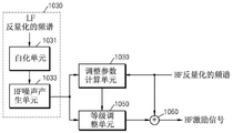
Fig. 10 is a block diagram of an excitation signal generation unit according to another exemplary embodiment, wherein the excitation signal generation unit may generate an excitation signal for a frequency band R2 (i.e., a frequency band to which bits are allocated) in the BWE region R1.
The excitation signal generating unit shown in fig. 10 may include an adjustment parameter calculating unit 1010, a noise signal generating unit 1030, a level adjusting unit 1050, and a calculating unit 1060. These components may be integrated into at least one module and implemented by at least one processor (not shown).
Referring to fig. 10, since the frequency band R2 has pulses encoded according to FPC, a level adjustment can also be added to the generation of the HF excitation signal using the weight values. Random noise is not added to the frequency band R2 on which frequency domain encoding has been performed. Fig. 10 shows a case where the weight Ws (k) is 0, and when the weight Ws (k) is not zero, an HF noise signal is generated in the same manner as in the noise signal generation unit 930 of fig. 9, and the generated HF noise signal is mapped to an output of the noise signal generation unit 1030 of fig. 10. That is, the output of the noise signal generating unit 1030 of fig. 10 is the same as the output of the noise signal generating unit 930 of fig. 9.
The adjustment parameter calculation unit 1010 calculates parameters to be used for level adjustment. When the dequantized FPC signal of the frequency band R2 is defined as C (k), the maximum value of the absolute value is selected from C (k), the selected value is defined as Ap, and the position of a nonzero value as a result of FPC is defined as CPs. The energy of the signal N (k) (output of the noise signal generation unit 1030) is obtained at a position other than CPs, and the energy of the signal N (k) is defined as En. The adjustment parameter γ can be obtained using equation 4 based on En, ap and Tth0 for setting f _ flag (b) at the time of encoding.
Equation 4

In equation 4, att _ factor represents an adjustment constant.
The calculation unit 1060 may generate the HF excitation signal by multiplying the adjustment parameter γ by the noise signal N (k) supplied from the noise signal generation unit 1030.
Fig. 11 is a block diagram of an excitation signal generation unit according to another exemplary embodiment, wherein the excitation signal generation unit may generate excitation signals for all frequency bands in the BWE region R1.
The excitation signal generating unit shown in fig. 11 may include a weight value assigning unit 1110, a noise signal generating unit 1130, and a calculating unit 1150. These components may be integrated into at least one module and implemented by at least one processor (not shown). Since the noise signal generation unit 1130 and the calculation unit 1150 are the same as the noise signal generation unit 930 and the calculation unit 950 of fig. 9, a description thereof will not be repeated.
Referring to fig. 11, the weight assignment unit 1110 may assign a weight for each frame. The weight value indicates a mixing ratio of the HF noise signal generated based on the decoded LF signal and the random noise to the random noise.
The weight assignment unit 1110 receives BWE excitation type information parsed from the bitstream. The weight assignment unit 1110 sets Ws (k) = w00 (for all k) when the BWE excitation type is 0, sets Ws (k) = w01 (for all k) when the BWE excitation type is 1, sets Ws (k) = w02 (for all k) when the BWE excitation type is 2, and sets Ws (k) = w03 (for all k) when the BWE excitation type is 3. According to an embodiment of the present invention, w00=0.8, w01=0.5, w02=0.25, and w03=0.05 may be assigned. May be set to gradually decrease from w00 to w 03. Smoothing may also be performed for the assigned weights.
Regardless of the BWE excitation type information, the preset same weight value may be applied to the frequency band following a specific frequency in the BWE region R1. According to an exemplary embodiment, the same weight may always be used for a plurality of bands including the last band after a specific frequency in the BWE region R1, and the weight may be generated for the band before the specific frequency based on the BWE excitation type information. For example, w02 may be allocated to the values of all Ws (k) for the frequency band to which frequencies of 12KHz or above 12KHz belong. As a result, since the region in which the band for determining the pitch mean of the BWE excitation type is obtained at the encoding end may be limited to a specific frequency or lower even in the BWE region R1, the complexity of calculation may be reduced. According to an exemplary embodiment, the excitation type may be determined by an average value of the pitch for a specific frequency or lower (i.e., a low frequency portion in the BWE region R1), and the determined excitation type may also be applied to a specific frequency or higher (i.e., a high frequency portion in the BWE region R1). That is, since only one piece of excitation classification information is transmitted in units of frames, when the region for estimating the excitation classification information is narrow, accuracy up to the narrow region can be increased, thereby improving the restored sound quality. For the high frequency band in the BWE region R1, the possibility of sound quality degradation is small even if the same excitation classification is applied. In addition, when the BWE excitation type information is transmitted for each band, bits indicating the BWE excitation type information may be reduced.
When a scheme such as a Vector Quantization (VQ) scheme, other than the low-frequency energy transmission scheme, is applied to energy of high frequency, the low-frequency energy may be transmitted using lossless coding after scalar quantization, and the high-frequency energy may be transmitted after quantization according to another scheme. In this case, the last frequency band in the low frequency encoding region R0 and the first frequency band in the BWE region R1 may overlap each other. In addition, the bands in the BWE region R1 may be configured in another scheme to have a relatively dense band allocation structure.
For example, it may be configured that the last band in the low frequency encoding region R0 ends at 8.2KHz and the first band in the BWE region R1 starts at 8 KHz. In this case, there is an overlapping region between the low frequency encoding region R0 and the BWE region R1. As a result, two decoded spectra may be generated in the overlap region. One is a frequency spectrum generated by applying a decoding scheme for low frequencies and the other is a frequency spectrum generated by applying a decoding scheme for high frequencies. An overlap-and-add scheme may be applied so that the transition between the two spectra (i.e., the decoded spectrum for low frequencies and the decoded spectrum for high frequencies) is smoother. That is, the overlap region is reconfigured by simultaneously using two frequency spectrums, in which the contribution of the frequency spectrum generated according to the low frequency scheme is increased for the frequency spectrum close to the low frequency in the overlap region, and the contribution of the frequency spectrum generated according to the high frequency scheme is increased for the frequency spectrum close to the high frequency in the overlap region.
For example, when the last band in the low frequency encoding region R0 ends at 8.2KHz and the first band in the BWE region R1 starts at 8KHz, if 640 sampled spectra are constructed at a sampling rate of 32KHz, eight spectra (i.e., the 320 th to 327 th spectra) overlap and may be generated using equation 5.
Equation 5

Wherein k is more than or equal to L0 and less than or equal to L1. In the case of the equation 5, the, representing the spectrum decoded according to the low frequency scheme,
 denotes a spectrum decoded in accordance with a high-frequency scheme, L0 denotes the position of the start spectrum of a high frequency, L0 to L1 denote overlapping regions, w o The contribution is represented.
Fig. 13 is a graph for describing a contribution to be used to generate a spectrum existing in an overlap region after BWE processing at a decoding end according to an exemplary embodiment.
Referring to FIG. 13, w may be o0 (k) And w o1 (k) Selectively applied to w o (k) Wherein w is o0 (k) Indicating that the same weight is applied to both LF and HF decoding schemes, w o1 (k) Indicating that a larger weight is applied to the HF decoding scheme. For w o (k) Is whether or not pulses using FPC have been selected in the overlapping frequency band of low frequencies. When pulses in overlapping frequency bands of low frequencies have been selected and encoded, w o0 (k) For making the contribution of the spectrum generated at low frequencies effective up to the vicinity of L1, and the contribution of high frequencies is reduced. Basically, a spectrum generated according to a practical coding scheme may be compared to a spectrum of a signal generated through BWEWith a higher proximity to the original signal. By using this scheme, in the overlapping frequency band, a scheme for increasing the contribution of the spectrum closer to the original signal can be applied, and therefore, the smoothing effect and the improvement of the sound quality can be expected.
Fig. 14 is a block diagram of an audio encoding apparatus of a switching structure according to an exemplary embodiment.
The audio encoding apparatus shown in fig. 14 may include a signal classification unit 1410, a Time Domain (TD) encoding unit 1420, a TD extension encoding unit 1430, a Frequency Domain (FD) encoding unit 1440, and an FD extension encoding unit 1450.
The signal classifying unit 1410 may determine an encoding mode of the input signal by referring to characteristics of the input signal. The signal classifying unit 1410 may determine the encoding mode of the input signal by considering TD characteristics and FD characteristics of the input signal. In addition, the signal classifying unit 1410 may determine that TD encoding of the input signal is performed when the characteristic of the input signal corresponds to a voice signal, and FD encoding of the input signal is performed when the characteristic of the input signal corresponds to an audio signal other than the voice signal.
The input signal input to the signal classifying unit 1410 may be a signal down-sampled by a down-sampling unit (not shown). According to an exemplary embodiment, the input signal may be a signal having a sampling rate of 12.8KHz or 16KHz obtained by resampling a signal having a sampling rate of 32KHz or 48 KHz. In this case, the signal having a sampling rate of 32KHz may be an ultra wide band (SWB) signal that can be a Full Band (FB) signal. In addition, the signal with the sampling rate of 16KHz may be a Wideband (WB) signal.
Accordingly, the signal classifying unit 1410 may determine a coding mode of an LF signal present in an LF region of the input signal as any one of a TD mode and an FD mode by referring to characteristics of the LF signal.
When the encoding mode of the input signal is determined to be the TD mode, the TD encoding unit 1420 may perform CELP encoding on the input signal. The TD encoding unit 1420 may extract an excitation signal from the input signal and quantize the extracted excitation signal by considering adaptive codebook contribution and fixed codebook contribution corresponding to pitch information.
According to another exemplary embodiment, the TD encoding unit 1420 may further include extracting Linear Prediction Coefficients (LPCs) from the input signal, quantizing the extracted LPCs, and extracting the excitation signal by using the quantized LPCs.
In addition, the TD encoding unit 1420 may perform CELP encoding in various encoding modes according to characteristics of the input signal. For example, the TD encoding unit 1420 may perform CELP encoding on the input signal in any one of a pool sound encoding (voiced coding) mode, an unvoiced sound encoding (unvoiced coding) mode, a transition mode, and a general encoding mode.
When CELP coding is performed on an LF signal in an input signal, the TD extension coding unit 1430 may perform extension coding on an HF signal in the input signal. For example, the TD extension encoding unit 1430 may quantize the LPC of the HF signal corresponding to the HF region of the input signal. In this case, TD extension encoding section 1430 may extract LPC for the HF signal in the input signal and quantize the extracted LPC. According to an exemplary embodiment, the TD extension encoding unit 1430 may generate the LPC of the HF signal in the input signal by using the excitation signal of the LF signal in the input signal.
The FD encoding unit 1440 may perform FD encoding on the input signal when the encoding mode of the input signal is determined to be the FD mode. For this purpose, the FD encoding unit 1440 may transform the input signal into a frequency-domain spectrum using MDCT or the like, and quantize and lossless encode the transformed spectrum. According to an exemplary embodiment, an FPC may be applied thereto.
The FD extension encoding unit 1450 may perform extension encoding on an HF signal among the input signals. According to an exemplary embodiment, the FD extension coding unit 1450 may perform FD extension by using an LF spectrum.
Fig. 15 is a block diagram of an audio encoding apparatus of a switching structure according to another exemplary embodiment.
The audio encoding apparatus shown in fig. 15 may include a signal classification unit 1510, an LPC encoding unit 1520, a TD encoding unit 1530, a TD extension encoding unit 1540, an audio encoding unit 1550, and an FD extension encoding unit 1560.
Referring to fig. 15, the signal classifying unit 1510 may determine an encoding mode of an input signal by referring to characteristics of the input signal. The signal classifying unit 1510 may determine a coding mode of the input signal by considering TD characteristics and FD characteristics of the input signal. The signal classifying unit 1510 may determine that TD encoding of the input signal is performed when the characteristics of the input signal correspond to a voice signal, and audio encoding of the input signal is performed when the characteristics of the input signal correspond to an audio signal other than the voice signal.
The LPC encoding unit 1520 may extract an LPC from the input signal and quantize the extracted LPC. According to an exemplary embodiment, the LPC encoding unit 1520 may quantize the LPC by using a trellis-coded quantization (TCQ) scheme, a multi-level vector quantization (MSVQ) scheme, a trellis-vector quantization (LVQ) scheme, or the like, but is not limited thereto.
In detail, the LPC encoding unit 1520 may extract LPC from an LF signal in an input signal having a sampling rate of 12.8KHz or 16KHz by re-sampling the input signal having a sampling rate of 32KHz or 48 KHz. The LPC encoding unit 1520 may further include extracting an LPC excitation signal by using the quantized LPC.
When the coding mode of the input signal is determined to be the TD mode, the TD coding unit 1530 may perform CELP coding on the LPC excitation signal extracted using LPC. For example, the TD encoding unit 1530 may quantize the LPC excitation signal by considering the adaptive codebook contribution and the fixed codebook contribution corresponding to the pitch information. The LPC excitation signal may be generated by at least one of the LPC encoding unit 1520 and the TD encoding unit 1530.
When CELP encoding is performed on the LPC excitation signal of the LF signal in the input signal, the TD extension encoding unit 1540 may perform extension encoding on the HF signal in the input signal. For example, the TD extension encoding unit 1540 may quantize the LPC of the HF signal in the input signal. According to an embodiment of the present invention, the TD extension encoding unit 1540 may extract the LPC of the HF signal in the input signal by using the LPC excitation signal of the LF signal in the input signal.
When the encoding mode of the input signal is determined to be the audio mode, the audio encoding unit 1550 may perform audio encoding on the LPC excitation signal extracted using the LPC. For example, the audio encoding unit 1550 may transform the LPC excitation signal extracted using LPC into an LPC excitation spectrum of the frequency domain and quantize the transformed LPC excitation spectrum. The audio encoding unit 1550 may quantize the LPC excitation spectrum, which has been transformed in the frequency domain, according to the FPC scheme or the LVQ scheme.
In addition, when there are residual bits in the quantization of the LPC excitation spectrum, the audio encoding unit 1550 may quantize the LPC excitation spectrum by further considering TD encoding information such as adaptive codebook contribution and fixed codebook contribution.
When performing audio encoding on the LPC excitation signal of the LF signal in the input signal, the FD extension encoding unit 1560 may perform extension encoding on the HF signal in the input signal. That is, the FD extension coding unit 1560 may perform HF extension coding by using the LF spectrum.
The FD extension encoding units 1450 and 1560 may be implemented by the audio encoding apparatus of fig. 3 or fig. 6.
Fig. 16 is a block diagram of an audio decoding apparatus of a switching structure according to an exemplary embodiment.
Referring to fig. 16, the audio decoding apparatus may include a mode information checking unit 1610, a TD decoding unit 1620, a TD extension decoding unit 1630, an FD decoding unit 1640, and an FD extension decoding unit 1650.
The mode information checking unit 1610 may check mode information of each frame included in the bitstream. The mode information checking unit 1610 may parse mode information from a bitstream and switch to any one of a TD decoding mode and an FD decoding mode according to an encoding mode of a current frame from a parsing result.
In detail, the mode information checking unit 1610 may switch for each frame included in the bitstream to perform CELP decoding on a frame encoded in the TD mode and FD decoding on a frame encoded in the FD mode.
The TD decoding unit 1620 may perform CELP decoding on the CELP-encoded frame according to the check result. For example, the TD decoding unit 1620 may generate an LF signal that is a low-frequency decoded signal by decoding LPCs included in a bitstream, decoding an adaptive codebook contribution and a fixed codebook contribution, and synthesizing the decoding result.
The TD extension decoding unit 1630 may generate a decoded signal of a high frequency by using at least one of a CELP decoding result of the LF signal and the excitation signal. The excitation signal of the LF signal may be included in the bitstream. In addition, the TD extension decoding unit 1630 may use LPC information on the HF signal included in the bitstream to generate the HF signal that is a decoded signal of high frequency.
According to an exemplary embodiment, the TD extension decoding unit 1630 may generate a decoded signal by synthesizing the generated HF signal and the LF signal generated by the TD decoding unit 1620. At this time, the TD extension decoding unit 1630 may also convert the sampling rates of the LF signal and the HF signal to be the same to generate a decoded signal.
The FD decoding unit 1640 may perform FD decoding on the FD encoded frame according to the check result. According to an exemplary embodiment, the FD decoding unit 1640 may perform lossless decoding and inverse quantization by referring to mode information of a previous frame included in a bitstream. At this time, FPC decoding may be applied, and noise may be added to a predetermined frequency band as a result of the FPC decoding.
The FD extension decoding unit 1650 may perform HF extension decoding by using the result of FPC decoding and/or noise padding in the FD decoding unit 1640. The FD extension decoding unit 1650 may generate a decoded HF signal by: the method comprises the steps of dequantizing the energy of the decoded spectrum of the LF band, generating an excitation signal of the HF signal by using the LF signal according to any one of various HF BWE modes, and applying a gain such that the energy of the generated excitation signal is symmetrical to the dequantized energy. For example, the HF BWE mode may be any one of a normal mode, a harmonic mode, and a noise mode.
FIG. 17 is a block diagram of an audio decoding apparatus of a switching structure according to another exemplary embodiment
Referring to fig. 17, the audio decoding apparatus may include a mode information checking unit 1710, an LPC decoding unit 1720, a TD decoding unit 1730, a TD extension decoding unit 1740, an audio decoding unit 1750, and an FD extension decoding unit 1760.
The mode information checking unit 1710 may check mode information of each frame included in the bitstream. For example, the mode information checking unit 1710 may parse mode information from the encoded bitstream and switch to any one of a TD decoding mode and an audio decoding mode according to an encoding mode of a current frame from a parsing result.
In detail, the mode information checking unit 1710 may switch for each frame included in the bitstream to perform CELP decoding on a frame encoded in the TD mode and audio decoding on a frame encoded in the audio mode.
The LPC decoding unit 1720 may LPC-decode the frame included in the bitstream.
The TD decoding unit 1730 may perform CELP decoding on the CELP-encoded frame according to the check result. For example, the TD decoding unit 1730 may generate an LF signal which is a low-frequency decoded signal by decoding the adaptive codebook contribution and the fixed codebook contribution and synthesizing the decoding results.
The TD extension decoding unit 1740 may generate a decoded signal of a high frequency by using at least one of a CELP decoding result of the LF signal and the excitation signal. The excitation signal of the LF signal may be included in the bitstream. TD extension decoding section 1740 may generate an HF signal, which is a high-frequency decoded signal, using the LPC information decoded by LPC decoding section 1720.
According to an exemplary embodiment, the TD extension decoding unit 1740 may generate a decoded signal by synthesizing the generated HF signal and the LF signal generated by the TD decoding unit 1730. At this time, the TD extension decoding unit 1740 may also convert the sampling rates of the LF signal and the HF signal to be the same to generate a decoded signal.
The audio decoding unit 1750 may perform audio decoding on the audio-encoded frame according to the check result. For example, when there is a TD contribution, the audio decoding unit 1750 may perform decoding by considering the TD contribution and the FD contribution, and when there is no TD contribution, the audio decoding unit 1750 may perform decoding by considering the FD contribution.
In addition, the audio decoding unit 1750 may generate a decoded LF signal by transforming a signal quantized according to an FPC or LVQ scheme to a time domain, and synthesizing the generated excitation signal with the inversely quantized LPC coefficients.
The FD extension decoding unit 1760 may perform extension decoding by using the audio decoding result. For example, the FD extension decoding unit 1760 may convert the sampling rate of the decoded LF signal into a sampling rate suitable for HF extension decoding, and perform frequency transformation of the converted signal by using MDCT or the like. The FD extension decoding unit 1760 may generate a decoded HF signal by: the energy of the transformed LF spectrum is dequantized, an excitation signal of the HF signal is generated by using the LF signal according to any one of various HF BWE modes, and a gain is applied such that the energy of the generated excitation signal is symmetrical to the dequantized energy. For example, the HF BWE mode may be any one of a normal mode, a transient mode, a harmonic mode, and a noise mode.
In addition, the FD extension decoding unit 1760 may transform the decoded HF signal into a signal of the time domain by using inverse MDCT, perform conversion to match the sampling rate of the signal transformed into the time domain with the sampling rate of the LF signal generated by the audio decoding unit 1750, and synthesize the LF signal and the converted signal.
The FD extension decoding units 1650 and 1760 illustrated in fig. 16 and 17 may be implemented by the audio decoding apparatus of fig. 8.
Fig. 18 is a block diagram of a multimedia device including an encoding module according to an exemplary embodiment.
Referring to fig. 18, the multimedia device 1800 may include a communication unit 1810 and an encoding module 1830. In addition, the multimedia device 1800 may further include a storage unit 1850 for storing an audio bitstream obtained as a result of encoding according to the use of the audio bitstream. Additionally, the multimedia device 1800 may also include a microphone 1870. That is, the memory unit 1850 and the microphone 1870 may be selectively included. The multimedia device 1800 may further include any decoding module (not shown), for example, a decoding module for performing a general decoding function or a decoding module according to an exemplary embodiment. The encoding module 1830 may be implemented by at least one processor, e.g., a central processing unit (not shown), by being integrated with other components (not shown) included in the multimedia device 1800.
The communication unit 1810 may receive at least one of an audio signal or an encoded bitstream provided from the outside or transmit at least one of a restored audio signal and an encoded bitstream obtained as a result of encoding by the encoding module 1830.
The communication unit 1810 is configured to transmit and receive data to and from an external multimedia device through a wireless network, such as a wireless internet, a wireless intranet, a wireless phone network, a wireless Local Area Network (LAN), wi-Fi direct (WFD), third generation (3G), fourth generation (4G), bluetooth, infrared data association (IrDA), radio Frequency Identification (RFID), ultra Wideband (UWB), zigbee, or Near Field Communication (NFC), or a wired network, such as a wired phone network or a wired internet.
According to an exemplary embodiment, the encoding module 1830 may encode the audio signal of the time domain provided through the communication unit 1810 or the microphone 1870 by using the encoding apparatus of fig. 14 or 15. In addition, the FD extension coding may be performed by using the encoding apparatus of fig. 3 or 6.
The memory unit 1850 may store the encoded bitstream generated by the encoding module 1830. In addition, the memory unit 1850 may store various programs required for operating the multimedia device 1800.
The microphone 1870 may provide an audio signal from a user or the outside to the encoding module 1830.
Fig. 19 is a block diagram of a multimedia device including a decoding module according to an exemplary embodiment.
The multimedia device 1900 of fig. 19 may include a communication unit 1910 and a decoding module 1930. In addition, the multimedia device 1900 of fig. 19 may further include a storage unit 1950 for storing the restored audio signal according to the use of the restored audio signal obtained as the decoding result. In addition, the multimedia device 1900 of fig. 19 may further include a speaker 1970. That is, the storage unit 1950 and the speaker 1970 are optional. The multimedia device 1900 of fig. 19 may further include an encoding module (not shown), for example, an encoding module for performing a general encoding function or an encoding module according to an exemplary embodiment. The decoding module 1930 may be integrated with other components (not shown) included in the multimedia device 1900 and implemented by at least one processor, e.g., a Central Processing Unit (CPU).
Referring to fig. 19, the communication unit 1910 may receive at least one of an audio signal or an encoded bitstream provided from the outside or may transmit at least one of a restored audio signal obtained as a result of decoding by the decoding module 1930 and an audio bitstream obtained as a result of encoding. Communications unit 1910 may be implemented substantially similarly to communications unit 1810 of fig. 18.
According to an exemplary embodiment, the decoding module 1930 may receive the bitstream provided through the communication unit 1910 and decode the bitstream by using the decoding apparatus of fig. 16 or 17. In addition, FD extension decoding may be performed by using the decoding apparatus of fig. 8 (in detail, the excitation signal generation unit of fig. 9 to 11).
The storage unit 1950 may store the restored audio signal generated by the decoding module 1930. In addition, the storage unit 1950 may store various programs required to operate the multimedia device 1900.
The speaker 1970 may output the restored audio signal generated by the decoding module 1930 to the outside.
Fig. 20 is a block diagram of a multimedia device including an encoding module and a decoding module according to an exemplary embodiment.
The multimedia device 2000 illustrated in fig. 20 may include a communication unit 2010, an encoding module 2020, and a decoding module 2030. In addition, the multimedia device 2000 may further include: a storage unit 2040 for storing an audio bitstream obtained as a result of encoding or a restored audio signal obtained as a result of decoding, according to the use of the audio bitstream or the restored audio signal. Additionally, the multimedia device 2000 may also include a microphone 2050 and/or a speaker 2060. The encoding module 2020 and the decoding module 2030 may be implemented by at least one processor, e.g., a Central Processing Unit (CPU) (not shown), by being integrated with other components (not shown) included in the multimedia device 2000.
Since components of the multimedia device 2000 illustrated in fig. 20 correspond to components of the multimedia device 1800 illustrated in fig. 18 or components of the multimedia device 1900 illustrated in fig. 19, detailed descriptions thereof are omitted.
Each of the multimedia devices 1800, 1900, and 2000 illustrated in fig. 18, 19, and 20 may include a terminal for voice communication only, such as a phone or a mobile phone, a device for broadcasting or music only, such as a TV or MP3 player, or a hybrid terminal device of a terminal for voice communication only and a device for broadcasting or music only, but is not limited thereto. In addition, each of the multimedia devices 1800, 1900, and 2000 may function as a client, a server, or a transducer disposed between a client and a server.
When the multimedia device 1800, 1900, or 2000 is, for example, a mobile phone (although not shown), the multimedia device 1800, 1900, or 2000 may further include a user input unit such as a keypad, a display unit for displaying information processed by a user interface or the mobile phone, and a processor for controlling functions of the mobile phone. In addition, the mobile phone may further include a camera unit having an image pickup function and at least one component for performing a function required for the mobile phone.
When the multimedia device 1800, 1900, or 2000 is, for example, a TV (although not shown), the multimedia device 1800, 1900, or 2000 may further include a user input unit such as a keypad, a display unit for displaying received broadcast information, and a processor for controlling all functions of the TV. In addition, the TV may further include at least one component for performing functions of the TV.
The method according to the embodiment may be written as a computer-executable program and may be implemented in a general-purpose digital computer that executes the program by using a non-transitory computer-readable recording medium. In addition, a data structure, program instructions, or data files that may be used in embodiments may be recorded on a non-transitory computer-readable recording medium in various ways. The non-transitory computer readable recording medium is any data storage device that can store data which can be thereafter read by a computer system. Examples of the non-transitory computer-readable recording medium include magnetic storage media (such as hard disks, floppy disks, and magnetic tapes), optical recording media (such as CD-ROMs, DVDs), magneto-optical media (such as optical disks), and hardware devices (such as ROMs, RAMs, and flash memories) specifically configured to store and execute program instructions. In addition, the non-transitory computer-readable recording medium may be a transmission medium for transmitting a signal specifying the program instructions, the data structures, and the like. Examples of the program instructions may include not only machine language code created by a compiler, but also high-level language code that may be executed by a computer using an interpreter or the like.
While exemplary embodiments have been particularly shown and described, it will be understood by those of ordinary skill in the art that various changes in form and details may be made therein without departing from the spirit and scope of the inventive concept as defined by the following claims.
Claims (5)
1. A method of generating a high frequency excitation spectrum, the method comprising:
receiving a bitstream, wherein the bitstream includes one of first excitation classification information and second excitation classification information as an excitation classification of a current frame;
decoding a low frequency spectrum of a current frame from the bitstream;
obtaining a high-frequency excitation spectrum of the current frame from the decoded low-frequency spectrum based on the excitation classification of the current frame;
wherein the first excitation classification information for the current frame indicates that the excitation classification of the current frame corresponds to the speech classification if the current frame has speech characteristics,
wherein the second excitation classification information for the current frame indicates whether the excitation classification of the current frame corresponds to the first non-speech classification or the second non-speech classification based on the pitch characteristic of the current frame if the current frame does not have the speech characteristic.
2. The method of claim 1, wherein the second excitation classification information for the current frame is determined based on whether the current frame corresponds to a noise signal or a pitch signal by comparing the pitch characteristic to a threshold when the current frame does not have a speech characteristic.
3. The method of claim 1, further comprising: the bandwidth-extended spectrum of the current frame is generated from the decoded spectrum of the current frame and the high-frequency excitation spectrum of the current frame.
4. An apparatus for generating an excitation classification, the apparatus comprising:
at least one processor configured to:
determining whether a current frame of the audio signal corresponds to a speech signal based on a result of the signal classification;
generating first excitation classification information for the current frame in response to the current frame corresponding to the speech signal;
when the current frame of the audio signal does not correspond to the voice signal, obtaining the tone characteristic of the current frame;
generating second excitation classification information for the current frame by comparing the pitch characteristic to a threshold;
generating a bitstream comprising the first excitation classification information or the second excitation classification information,
wherein the first excitation classification information indicates that the classification of the current frame is a speech classification;
wherein the second excitation classification information indicates whether the classification of the current frame is the first non-speech classification or the second non-speech classification.
5. The device of claim 4, wherein the at least one processor is configured to: when the current frame of the audio signal does not correspond to a speech signal, determining second excitation classification information for the current frame based on whether the current frame corresponds to a noise signal or a pitch signal by comparing the pitch characteristic to the threshold.
Applications Claiming Priority (6)
| Application Number | Priority Date | Filing Date | Title |
|---|---|---|---|
| US201261613610P | 2012-03-21 | 2012-03-21 | |
| US61/613,610 | 2012-03-21 | ||
| US201261719799P | 2012-10-29 | 2012-10-29 | |
| US61/719,799 | 2012-10-29 | ||
| CN201380026924.2A CN104321815B (en) | 2012-03-21 | 2013-03-21 | High-frequency coding/high frequency decoding method and apparatus for bandwidth expansion |
| PCT/KR2013/002372 WO2013141638A1 (en) | 2012-03-21 | 2013-03-21 | Method and apparatus for high-frequency encoding/decoding for bandwidth extension |
Related Parent Applications (1)
| Application Number | Title | Priority Date | Filing Date |
|---|---|---|---|
| CN201380026924.2A Division CN104321815B (en) | 2012-03-21 | 2013-03-21 | High-frequency coding/high frequency decoding method and apparatus for bandwidth expansion |
Publications (2)
| Publication Number | Publication Date |
|---|---|
| CN108831501A CN108831501A (en) | 2018-11-16 |
| CN108831501B true CN108831501B (en) | 2023-01-10 |
Family
ID=49223006
Family Applications (2)
| Application Number | Title | Priority Date | Filing Date |
|---|---|---|---|
| CN201811081766.1A Active CN108831501B (en) | 2012-03-21 | 2013-03-21 | High frequency encoding/decoding method and apparatus for bandwidth extension |
| CN201380026924.2A Active CN104321815B (en) | 2012-03-21 | 2013-03-21 | High-frequency coding/high frequency decoding method and apparatus for bandwidth expansion |
Family Applications After (1)
| Application Number | Title | Priority Date | Filing Date |
|---|---|---|---|
| CN201380026924.2A Active CN104321815B (en) | 2012-03-21 | 2013-03-21 | High-frequency coding/high frequency decoding method and apparatus for bandwidth expansion |
Country Status (8)
| Country | Link |
|---|---|
| US (3) | US9378746B2 (en) |
| EP (2) | EP2830062B1 (en) |
| JP (2) | JP6306565B2 (en) |
| KR (3) | KR102070432B1 (en) |
| CN (2) | CN108831501B (en) |
| ES (1) | ES2762325T3 (en) |
| TW (2) | TWI591620B (en) |
| WO (1) | WO2013141638A1 (en) |
Families Citing this family (31)
| Publication number | Priority date | Publication date | Assignee | Title |
|---|---|---|---|---|
| IL294836B1 (en) * | 2013-04-05 | 2024-06-01 | Dolby Int Ab | Audio encoder and decoder |
| US8982976B2 (en) * | 2013-07-22 | 2015-03-17 | Futurewei Technologies, Inc. | Systems and methods for trellis coded quantization based channel feedback |
| WO2015037969A1 (en) * | 2013-09-16 | 2015-03-19 | 삼성전자 주식회사 | Signal encoding method and device and signal decoding method and device |
| CN110634495B (en) | 2013-09-16 | 2023-07-07 | 三星电子株式会社 | Signal encoding method and device and signal decoding method and device |
| KR102023138B1 (en) * | 2013-12-02 | 2019-09-19 | 후아웨이 테크놀러지 컴퍼니 리미티드 | Encoding method and apparatus |
| FR3017484A1 (en) | 2014-02-07 | 2015-08-14 | Orange | ENHANCED FREQUENCY BAND EXTENSION IN AUDIO FREQUENCY SIGNAL DECODER |
| KR102625143B1 (en) * | 2014-02-17 | 2024-01-15 | 삼성전자주식회사 | Signal encoding method and apparatus, and signal decoding method and apparatus |
| US10395663B2 (en) | 2014-02-17 | 2019-08-27 | Samsung Electronics Co., Ltd. | Signal encoding method and apparatus, and signal decoding method and apparatus |
| CN105659321B (en) * | 2014-02-28 | 2020-07-28 | 弗朗霍弗应用研究促进协会 | Decoding device and decoding method |
| WO2015133795A1 (en) * | 2014-03-03 | 2015-09-11 | 삼성전자 주식회사 | Method and apparatus for high frequency decoding for bandwidth extension |
| EP3115991A4 (en) * | 2014-03-03 | 2017-08-02 | Samsung Electronics Co., Ltd. | Method and apparatus for high frequency decoding for bandwidth extension |
| CN110808056B (en) * | 2014-03-14 | 2023-10-17 | 瑞典爱立信有限公司 | Audio coding method and device |
| CN104934034B (en) * | 2014-03-19 | 2016-11-16 | 华为技术有限公司 | Method and apparatus for signal processing |
| US10468035B2 (en) | 2014-03-24 | 2019-11-05 | Samsung Electronics Co., Ltd. | High-band encoding method and device, and high-band decoding method and device |
| EP2980792A1 (en) | 2014-07-28 | 2016-02-03 | Fraunhofer-Gesellschaft zur Förderung der angewandten Forschung e.V. | Apparatus and method for generating an enhanced signal using independent noise-filling |
| EP4293666A3 (en) | 2014-07-28 | 2024-03-06 | Samsung Electronics Co., Ltd. | Signal encoding method and apparatus and signal decoding method and apparatus |
| FR3024581A1 (en) | 2014-07-29 | 2016-02-05 | Orange | DETERMINING A CODING BUDGET OF A TRANSITION FRAME LPD / FD |
| JP2016038435A (en) | 2014-08-06 | 2016-03-22 | ソニー株式会社 | Encoding device and method, decoding device and method, and program |
| US10304474B2 (en) | 2014-08-15 | 2019-05-28 | Samsung Electronics Co., Ltd. | Sound quality improving method and device, sound decoding method and device, and multimedia device employing same |
| US10847170B2 (en) | 2015-06-18 | 2020-11-24 | Qualcomm Incorporated | Device and method for generating a high-band signal from non-linearly processed sub-ranges |
| US9837089B2 (en) * | 2015-06-18 | 2017-12-05 | Qualcomm Incorporated | High-band signal generation |
| US9978392B2 (en) * | 2016-09-09 | 2018-05-22 | Tata Consultancy Services Limited | Noisy signal identification from non-stationary audio signals |
| CN108630212B (en) * | 2018-04-03 | 2021-05-07 | 湖南商学院 | Perception reconstruction method and device for high-frequency excitation signal in non-blind bandwidth extension |
| US11133891B2 (en) | 2018-06-29 | 2021-09-28 | Khalifa University of Science and Technology | Systems and methods for self-synchronized communications |
| US10951596B2 (en) * | 2018-07-27 | 2021-03-16 | Khalifa University of Science and Technology | Method for secure device-to-device communication using multilayered cyphers |
| JP6903242B2 (en) * | 2019-01-31 | 2021-07-14 | 三菱電機株式会社 | Frequency band expansion device, frequency band expansion method, and frequency band expansion program |
| EP3751567B1 (en) * | 2019-06-10 | 2022-01-26 | Axis AB | A method, a computer program, an encoder and a monitoring device |
| CN113539281B (en) * | 2020-04-21 | 2024-09-06 | 华为技术有限公司 | Audio signal encoding method and apparatus |
| CN113808596A (en) * | 2020-05-30 | 2021-12-17 | 华为技术有限公司 | Audio coding method and audio coding device |
| CN113963703A (en) * | 2020-07-03 | 2022-01-21 | 华为技术有限公司 | Audio coding method and coding and decoding equipment |
| CN113270105B (en) * | 2021-05-20 | 2022-05-10 | 东南大学 | Voice-like data transmission method based on hybrid modulation |
Citations (6)
| Publication number | Priority date | Publication date | Assignee | Title |
|---|---|---|---|---|
| CN1338096A (en) * | 1998-12-30 | 2002-02-27 | 诺基亚移动电话有限公司 | Adaptive windows for analysis-by-synthesis CELP-type speech coding |
| CN101083076A (en) * | 2006-06-03 | 2007-12-05 | 三星电子株式会社 | Method and apparatus to encode and/or decode signal using bandwidth extension technology |
| CN101089951A (en) * | 2006-06-16 | 2007-12-19 | 徐光锁 | Band spreading coding method and device and decode method and device |
| CN101568959A (en) * | 2006-11-17 | 2009-10-28 | 三星电子株式会社 | Method, medium, and apparatus with bandwidth extension encoding and/or decoding |
| EP2273493A1 (en) * | 2009-06-29 | 2011-01-12 | Fraunhofer-Gesellschaft zur Förderung der angewandten Forschung e.V. | Bandwidth extension encoder, bandwidth extension decoder and phase vocoder |
| CN101965612A (en) * | 2008-03-03 | 2011-02-02 | Lg电子株式会社 | The method and apparatus that is used for audio signal |
Family Cites Families (72)
| Publication number | Priority date | Publication date | Assignee | Title |
|---|---|---|---|---|
| US524323A (en) * | 1894-08-14 | Benfabriken | ||
| GB1218015A (en) * | 1967-03-13 | 1971-01-06 | Nat Res Dev | Improvements in or relating to systems for transmitting television signals |
| US4890328A (en) * | 1985-08-28 | 1989-12-26 | American Telephone And Telegraph Company | Voice synthesis utilizing multi-level filter excitation |
| US4771465A (en) * | 1986-09-11 | 1988-09-13 | American Telephone And Telegraph Company, At&T Bell Laboratories | Digital speech sinusoidal vocoder with transmission of only subset of harmonics |
| KR940004026Y1 (en) | 1991-05-13 | 1994-06-17 | 금성일렉트론 주식회사 | Bias start up circuit |
| BR9206143A (en) * | 1991-06-11 | 1995-01-03 | Qualcomm Inc | Vocal end compression processes and for variable rate encoding of input frames, apparatus to compress an acoustic signal into variable rate data, prognostic encoder triggered by variable rate code (CELP) and decoder to decode encoded frames |
| US5721788A (en) | 1992-07-31 | 1998-02-24 | Corbis Corporation | Method and system for digital image signatures |
| US5455888A (en) * | 1992-12-04 | 1995-10-03 | Northern Telecom Limited | Speech bandwidth extension method and apparatus |
| US6983051B1 (en) * | 1993-11-18 | 2006-01-03 | Digimarc Corporation | Methods for audio watermarking and decoding |
| US6614914B1 (en) * | 1995-05-08 | 2003-09-02 | Digimarc Corporation | Watermark embedder and reader |
| US5602961A (en) * | 1994-05-31 | 1997-02-11 | Alaris, Inc. | Method and apparatus for speech compression using multi-mode code excited linear predictive coding |
| US5732389A (en) * | 1995-06-07 | 1998-03-24 | Lucent Technologies Inc. | Voiced/unvoiced classification of speech for excitation codebook selection in celp speech decoding during frame erasures |
| US5664055A (en) * | 1995-06-07 | 1997-09-02 | Lucent Technologies Inc. | CS-ACELP speech compression system with adaptive pitch prediction filter gain based on a measure of periodicity |
| US5781881A (en) * | 1995-10-19 | 1998-07-14 | Deutsche Telekom Ag | Variable-subframe-length speech-coding classes derived from wavelet-transform parameters |
| US6570991B1 (en) * | 1996-12-18 | 2003-05-27 | Interval Research Corporation | Multi-feature speech/music discrimination system |
| US7024355B2 (en) * | 1997-01-27 | 2006-04-04 | Nec Corporation | Speech coder/decoder |
| US6819863B2 (en) * | 1998-01-13 | 2004-11-16 | Koninklijke Philips Electronics N.V. | System and method for locating program boundaries and commercial boundaries using audio categories |
| ATE302991T1 (en) * | 1998-01-22 | 2005-09-15 | Deutsche Telekom Ag | METHOD FOR SIGNAL-CONTROLLED SWITCHING BETWEEN DIFFERENT AUDIO CODING SYSTEMS |
| US6104992A (en) * | 1998-08-24 | 2000-08-15 | Conexant Systems, Inc. | Adaptive gain reduction to produce fixed codebook target signal |
| US6456964B2 (en) * | 1998-12-21 | 2002-09-24 | Qualcomm, Incorporated | Encoding of periodic speech using prototype waveforms |
| SE9903553D0 (en) | 1999-01-27 | 1999-10-01 | Lars Liljeryd | Enhancing conceptual performance of SBR and related coding methods by adaptive noise addition (ANA) and noise substitution limiting (NSL) |
| US6298322B1 (en) * | 1999-05-06 | 2001-10-02 | Eric Lindemann | Encoding and synthesis of tonal audio signals using dominant sinusoids and a vector-quantized residual tonal signal |
| JP4438127B2 (en) * | 1999-06-18 | 2010-03-24 | ソニー株式会社 | Speech encoding apparatus and method, speech decoding apparatus and method, and recording medium |
| JP4792613B2 (en) * | 1999-09-29 | 2011-10-12 | ソニー株式会社 | Information processing apparatus and method, and recording medium |
| FR2813722B1 (en) * | 2000-09-05 | 2003-01-24 | France Telecom | METHOD AND DEVICE FOR CONCEALING ERRORS AND TRANSMISSION SYSTEM COMPRISING SUCH A DEVICE |
| SE0004187D0 (en) * | 2000-11-15 | 2000-11-15 | Coding Technologies Sweden Ab | Enhancing the performance of coding systems that use high frequency reconstruction methods |
| US20020128839A1 (en) * | 2001-01-12 | 2002-09-12 | Ulf Lindgren | Speech bandwidth extension |
| US6694293B2 (en) * | 2001-02-13 | 2004-02-17 | Mindspeed Technologies, Inc. | Speech coding system with a music classifier |
| DE10134471C2 (en) * | 2001-02-28 | 2003-05-22 | Fraunhofer Ges Forschung | Method and device for characterizing a signal and method and device for generating an indexed signal |
| SE522553C2 (en) * | 2001-04-23 | 2004-02-17 | Ericsson Telefon Ab L M | Bandwidth extension of acoustic signals |
| US6658383B2 (en) * | 2001-06-26 | 2003-12-02 | Microsoft Corporation | Method for coding speech and music signals |
| US7092877B2 (en) * | 2001-07-31 | 2006-08-15 | Turk & Turk Electric Gmbh | Method for suppressing noise as well as a method for recognizing voice signals |
| US7158931B2 (en) * | 2002-01-28 | 2007-01-02 | Phonak Ag | Method for identifying a momentary acoustic scene, use of the method and hearing device |
| JP3900000B2 (en) * | 2002-05-07 | 2007-03-28 | ソニー株式会社 | Encoding method and apparatus, decoding method and apparatus, and program |
| KR100503415B1 (en) | 2002-12-09 | 2005-07-22 | 한국전자통신연구원 | Transcoding apparatus and method between CELP-based codecs using bandwidth extension |
| US8243093B2 (en) | 2003-08-22 | 2012-08-14 | Sharp Laboratories Of America, Inc. | Systems and methods for dither structure creation and application for reducing the visibility of contouring artifacts in still and video images |
| KR100571831B1 (en) * | 2004-02-10 | 2006-04-17 | 삼성전자주식회사 | Apparatus and method for distinguishing between vocal sound and other sound |
| FI118834B (en) * | 2004-02-23 | 2008-03-31 | Nokia Corp | Classification of audio signals |
| FI119533B (en) * | 2004-04-15 | 2008-12-15 | Nokia Corp | Coding of audio signals |
| GB0408856D0 (en) * | 2004-04-21 | 2004-05-26 | Nokia Corp | Signal encoding |
| CN1947174B (en) * | 2004-04-27 | 2012-03-14 | 松下电器产业株式会社 | Scalable encoding device, scalable decoding device, method thereof, and scalable coding device |
| US7457747B2 (en) * | 2004-08-23 | 2008-11-25 | Nokia Corporation | Noise detection for audio encoding by mean and variance energy ratio |
| CN101010730B (en) * | 2004-09-06 | 2011-07-27 | 松下电器产业株式会社 | Scalable decoding device and signal loss compensation method |
| KR20070085982A (en) * | 2004-12-10 | 2007-08-27 | 마츠시타 덴끼 산교 가부시키가이샤 | Wide-band encoding device, wide-band lsp prediction device, band scalable encoding device, wide-band encoding method |
| JP4793539B2 (en) * | 2005-03-29 | 2011-10-12 | 日本電気株式会社 | Code conversion method and apparatus, program, and storage medium therefor |
| NZ562182A (en) * | 2005-04-01 | 2010-03-26 | Qualcomm Inc | Method and apparatus for anti-sparseness filtering of a bandwidth extended speech prediction excitation signal |
| CA2558595C (en) * | 2005-09-02 | 2015-05-26 | Nortel Networks Limited | Method and apparatus for extending the bandwidth of a speech signal |
| KR20080101873A (en) * | 2006-01-18 | 2008-11-21 | 연세대학교 산학협력단 | Apparatus and method for encoding and decoding signal |
| EP1979901B1 (en) * | 2006-01-31 | 2015-10-14 | Unify GmbH & Co. KG | Method and arrangements for audio signal encoding |
| DE102006008298B4 (en) * | 2006-02-22 | 2010-01-14 | Fraunhofer-Gesellschaft zur Förderung der angewandten Forschung e.V. | Apparatus and method for generating a note signal |
| US8532984B2 (en) * | 2006-07-31 | 2013-09-10 | Qualcomm Incorporated | Systems, methods, and apparatus for wideband encoding and decoding of active frames |
| US9454974B2 (en) * | 2006-07-31 | 2016-09-27 | Qualcomm Incorporated | Systems, methods, and apparatus for gain factor limiting |
| CN101145345B (en) * | 2006-09-13 | 2011-02-09 | 华为技术有限公司 | Audio frequency classification method |
| US8639500B2 (en) | 2006-11-17 | 2014-01-28 | Samsung Electronics Co., Ltd. | Method, medium, and apparatus with bandwidth extension encoding and/or decoding |
| US8990073B2 (en) * | 2007-06-22 | 2015-03-24 | Voiceage Corporation | Method and device for sound activity detection and sound signal classification |
| CN101393741A (en) * | 2007-09-19 | 2009-03-25 | 中兴通讯股份有限公司 | Audio signal classification apparatus and method used in wideband audio encoder and decoder |
| KR101441896B1 (en) * | 2008-01-29 | 2014-09-23 | 삼성전자주식회사 | Method and apparatus for encoding/decoding audio signal using adaptive LPC coefficient interpolation |
| CN101515454B (en) * | 2008-02-22 | 2011-05-25 | 杨夙 | Signal characteristic extracting methods for automatic classification of voice, music and noise |
| CN101751926B (en) | 2008-12-10 | 2012-07-04 | 华为技术有限公司 | Signal coding and decoding method and device, and coding and decoding system |
| CN101751920A (en) * | 2008-12-19 | 2010-06-23 | 数维科技(北京)有限公司 | Audio classification and implementation method based on reclassification |
| DK2211339T3 (en) * | 2009-01-23 | 2017-08-28 | Oticon As | listening System |
| CN101847412B (en) * | 2009-03-27 | 2012-02-15 | 华为技术有限公司 | Method and device for classifying audio signals |
| DK2328363T3 (en) * | 2009-09-11 | 2016-08-22 | Starkey Labs Inc | SOUND CLASSIFICATION SYSTEM FOR HEARING DEVICES |
| US8447617B2 (en) * | 2009-12-21 | 2013-05-21 | Mindspeed Technologies, Inc. | Method and system for speech bandwidth extension |
| CN102237085B (en) * | 2010-04-26 | 2013-08-14 | 华为技术有限公司 | Method and device for classifying audio signals |
| EP2593937B1 (en) * | 2010-07-16 | 2015-11-11 | Telefonaktiebolaget LM Ericsson (publ) | Audio encoder and decoder and methods for encoding and decoding an audio signal |
| SG10201505469SA (en) * | 2010-07-19 | 2015-08-28 | Dolby Int Ab | Processing of audio signals during high frequency reconstruction |
| JP5749462B2 (en) | 2010-08-13 | 2015-07-15 | 株式会社Nttドコモ | Audio decoding apparatus, audio decoding method, audio decoding program, audio encoding apparatus, audio encoding method, and audio encoding program |
| US8729374B2 (en) * | 2011-07-22 | 2014-05-20 | Howling Technology | Method and apparatus for converting a spoken voice to a singing voice sung in the manner of a target singer |
| CN103035248B (en) * | 2011-10-08 | 2015-01-21 | 华为技术有限公司 | Encoding method and device for audio signals |
| EP2798631B1 (en) * | 2011-12-21 | 2016-03-23 | Huawei Technologies Co., Ltd. | Adaptively encoding pitch lag for voiced speech |
| US9082398B2 (en) * | 2012-02-28 | 2015-07-14 | Huawei Technologies Co., Ltd. | System and method for post excitation enhancement for low bit rate speech coding |
-
2013
- 2013-03-21 EP EP13763979.5A patent/EP2830062B1/en active Active
- 2013-03-21 TW TW102110397A patent/TWI591620B/en active
- 2013-03-21 TW TW106118001A patent/TWI626645B/en active
- 2013-03-21 CN CN201811081766.1A patent/CN108831501B/en active Active
- 2013-03-21 EP EP19200892.8A patent/EP3611728A1/en not_active Ceased
- 2013-03-21 WO PCT/KR2013/002372 patent/WO2013141638A1/en active Application Filing
- 2013-03-21 CN CN201380026924.2A patent/CN104321815B/en active Active
- 2013-03-21 US US13/848,177 patent/US9378746B2/en active Active
- 2013-03-21 JP JP2015501583A patent/JP6306565B2/en active Active
- 2013-03-21 ES ES13763979T patent/ES2762325T3/en active Active
- 2013-03-21 KR KR1020130030587A patent/KR102070432B1/en active IP Right Grant
-
2016
- 2016-04-25 US US15/137,030 patent/US9761238B2/en active Active
-
2017
- 2017-09-11 US US15/700,737 patent/US10339948B2/en active Active
-
2018
- 2018-03-08 JP JP2018042308A patent/JP6673957B2/en active Active
-
2020
- 2020-01-20 KR KR1020200007392A patent/KR102194559B1/en active IP Right Grant
- 2020-12-17 KR KR1020200177443A patent/KR102248252B1/en active IP Right Grant
Patent Citations (7)
| Publication number | Priority date | Publication date | Assignee | Title |
|---|---|---|---|---|
| CN1338096A (en) * | 1998-12-30 | 2002-02-27 | 诺基亚移动电话有限公司 | Adaptive windows for analysis-by-synthesis CELP-type speech coding |
| CN101083076A (en) * | 2006-06-03 | 2007-12-05 | 三星电子株式会社 | Method and apparatus to encode and/or decode signal using bandwidth extension technology |
| CN101089951A (en) * | 2006-06-16 | 2007-12-19 | 徐光锁 | Band spreading coding method and device and decode method and device |
| CN101568959A (en) * | 2006-11-17 | 2009-10-28 | 三星电子株式会社 | Method, medium, and apparatus with bandwidth extension encoding and/or decoding |
| CN101965612A (en) * | 2008-03-03 | 2011-02-02 | Lg电子株式会社 | The method and apparatus that is used for audio signal |
| EP2273493A1 (en) * | 2009-06-29 | 2011-01-12 | Fraunhofer-Gesellschaft zur Förderung der angewandten Forschung e.V. | Bandwidth extension encoder, bandwidth extension decoder and phase vocoder |
| CN102473414A (en) * | 2009-06-29 | 2012-05-23 | 弗兰霍菲尔运输应用研究公司 | Bandwidth extension encoder, bandwidth extension decoder and phase vocoder |
Also Published As
| Publication number | Publication date |
|---|---|
| US20170372718A1 (en) | 2017-12-28 |
| WO2013141638A1 (en) | 2013-09-26 |
| KR20200010540A (en) | 2020-01-30 |
| EP2830062A1 (en) | 2015-01-28 |
| ES2762325T3 (en) | 2020-05-22 |
| KR102070432B1 (en) | 2020-03-02 |
| JP2015512528A (en) | 2015-04-27 |
| TWI626645B (en) | 2018-06-11 |
| JP6673957B2 (en) | 2020-04-01 |
| CN108831501A (en) | 2018-11-16 |
| KR20130107257A (en) | 2013-10-01 |
| US20160240207A1 (en) | 2016-08-18 |
| US20130290003A1 (en) | 2013-10-31 |
| KR20200144086A (en) | 2020-12-28 |
| EP2830062B1 (en) | 2019-11-20 |
| CN104321815A (en) | 2015-01-28 |
| JP2018116297A (en) | 2018-07-26 |
| EP3611728A1 (en) | 2020-02-19 |
| EP2830062A4 (en) | 2015-10-14 |
| CN104321815B (en) | 2018-10-16 |
| KR102248252B1 (en) | 2021-05-04 |
| TWI591620B (en) | 2017-07-11 |
| JP6306565B2 (en) | 2018-04-04 |
| US9378746B2 (en) | 2016-06-28 |
| KR102194559B1 (en) | 2020-12-23 |
| US9761238B2 (en) | 2017-09-12 |
| TW201729181A (en) | 2017-08-16 |
| US10339948B2 (en) | 2019-07-02 |
| TW201401267A (en) | 2014-01-01 |
Similar Documents
| Publication | Publication Date | Title |
|---|---|---|
| KR102248252B1 (en) | Method and apparatus for encoding and decoding high frequency for bandwidth extension | |
| JP6980871B2 (en) | Signal coding method and its device, and signal decoding method and its device | |
| US11676614B2 (en) | Method and apparatus for high frequency decoding for bandwidth extension | |
| CN105745703B (en) | Signal encoding method and apparatus, and signal decoding method and apparatus | |
| KR20150032220A (en) | Signal encoding method and apparatus and signal decoding method and apparatus | |
| KR20220051317A (en) | Method and apparatus for decoding high frequency for bandwidth extension |
Legal Events
| Date | Code | Title | Description |
|---|---|---|---|
| PB01 | Publication | ||
| PB01 | Publication | ||
| SE01 | Entry into force of request for substantive examination | ||
| SE01 | Entry into force of request for substantive examination | ||
| GR01 | Patent grant | ||
| GR01 | Patent grant |