CN108828362B - Wiring Harness Connector Reliability Test Device - Google Patents
Wiring Harness Connector Reliability Test Device Download PDFInfo
- Publication number
- CN108828362B CN108828362B CN201810699892.7A CN201810699892A CN108828362B CN 108828362 B CN108828362 B CN 108828362B CN 201810699892 A CN201810699892 A CN 201810699892A CN 108828362 B CN108828362 B CN 108828362B
- Authority
- CN
- China
- Prior art keywords
- testing
- test
- jacks
- socket
- wire harness
- Prior art date
- Legal status (The legal status is an assumption and is not a legal conclusion. Google has not performed a legal analysis and makes no representation as to the accuracy of the status listed.)
- Active
Links
- 238000012360 testing method Methods 0.000 title claims abstract description 216
- 230000003068 static effect Effects 0.000 claims abstract description 21
- 230000005669 field effect Effects 0.000 claims description 19
- 238000004891 communication Methods 0.000 claims description 7
- 239000003990 capacitor Substances 0.000 claims description 3
- 238000001514 detection method Methods 0.000 abstract description 18
- 238000010586 diagram Methods 0.000 description 11
- 230000000694 effects Effects 0.000 description 7
- 238000000034 method Methods 0.000 description 5
- 238000004519 manufacturing process Methods 0.000 description 4
- 238000012986 modification Methods 0.000 description 3
- 230000004048 modification Effects 0.000 description 3
- 101100517648 Saccharomyces cerevisiae (strain ATCC 204508 / S288c) NUM1 gene Proteins 0.000 description 1
- 101100129590 Schizosaccharomyces pombe (strain 972 / ATCC 24843) mcp5 gene Proteins 0.000 description 1
- 238000010276 construction Methods 0.000 description 1
- 230000007547 defect Effects 0.000 description 1
- 238000005516 engineering process Methods 0.000 description 1
- WABPQHHGFIMREM-UHFFFAOYSA-N lead(0) Chemical compound [Pb] WABPQHHGFIMREM-UHFFFAOYSA-N 0.000 description 1
- 238000012546 transfer Methods 0.000 description 1
Images


Classifications
-
- G—PHYSICS
- G01—MEASURING; TESTING
- G01R—MEASURING ELECTRIC VARIABLES; MEASURING MAGNETIC VARIABLES
- G01R31/00—Arrangements for testing electric properties; Arrangements for locating electric faults; Arrangements for electrical testing characterised by what is being tested not provided for elsewhere
- G01R31/003—Environmental or reliability tests
-
- G—PHYSICS
- G01—MEASURING; TESTING
- G01R—MEASURING ELECTRIC VARIABLES; MEASURING MAGNETIC VARIABLES
- G01R31/00—Arrangements for testing electric properties; Arrangements for locating electric faults; Arrangements for electrical testing characterised by what is being tested not provided for elsewhere
- G01R31/50—Testing of electric apparatus, lines, cables or components for short-circuits, continuity, leakage current or incorrect line connections
- G01R31/66—Testing of connections, e.g. of plugs or non-disconnectable joints
- G01R31/68—Testing of releasable connections, e.g. of terminals mounted on a printed circuit board
Landscapes
- Physics & Mathematics (AREA)
- General Physics & Mathematics (AREA)
- Engineering & Computer Science (AREA)
- Environmental & Geological Engineering (AREA)
- Testing Of Short-Circuits, Discontinuities, Leakage, Or Incorrect Line Connections (AREA)
Abstract
本发明公开了一种线束接插件可靠性测试装置,包括测试主板(1),测试主板(1)设置有振动装置(2);所述测试主板(1)上设置有至少两个测试模块(3);测试模块(3)用于连接线束接插件检测其故障状态信息。本发明提供了一种线束接插件可靠性测试装置,可以同时对多个线束插接件进行静态故障检测和动态故障检测,能够显著提高检测效率。
The invention discloses a reliability testing device for a wiring harness connector, comprising a testing main board (1), wherein the testing main board (1) is provided with a vibration device (2); the testing main board (1) is provided with at least two testing modules (1). 3); The test module (3) is used to connect the wiring harness connector to detect its fault state information. The invention provides a reliability testing device for a wiring harness connector, which can perform static fault detection and dynamic fault detection on a plurality of wiring harness connectors at the same time, and can significantly improve the detection efficiency.
Description
技术领域technical field
本发明涉及一种线束检测设备技术领域,具体涉及一种线束接插件可靠性测试装置。The invention relates to the technical field of wire harness testing equipment, in particular to a reliability testing device for wire harness connectors.
背景技术Background technique
常规线束接插件由导线和两端的接插件组成,线束测试是通过接插件将被测线束插在专用线束测试设备上,检测线束接插件是否存在断路、连接不良、引脚错位、引脚短路等故障状态。随着线束制造工艺的成熟,目前在线束生产流程中出现的故障率极低,为了提高测试效率,可以简化线束测试的功能和流程,采用成本更低的测试设备,不再判定和标识每个线束的故障类型,简化操作步骤,快速将故障线束筛选出来。Conventional wiring harness connectors are composed of wires and connectors at both ends. The wiring harness test is to insert the tested wiring harness into the special wiring harness testing equipment through the connectors to detect whether the wiring harness connectors are open circuit, poor connection, pin dislocation, pin short circuit, etc. fault state. With the maturity of the wire harness manufacturing process, the current failure rate in the wire harness production process is extremely low. In order to improve the test efficiency, the function and process of the wire harness test can be simplified, and the test equipment with lower cost can be used. The fault type of the wiring harness simplifies the operation steps and quickly screen out the faulty wiring harness.
线束接插件的可靠性测试包括静态测试和动态测试。静态测试是指线束在静止状态下进行检测,主要用于简单测试或者针对家用电器等处于静止状态使用的线束接插件。动态测试是指线束在振动环境下进行检测,主要用于汽车、工程机械、机器人等处于运动状态工作的装备。Reliability testing of wiring harness connectors includes static testing and dynamic testing. Static test refers to the detection of the wire harness in a static state, which is mainly used for simple testing or for wire harness connectors that are used in a static state such as household appliances. Dynamic testing refers to the detection of wire harnesses in a vibration environment, and is mainly used for equipment that is in motion, such as automobiles, construction machinery, and robots.
现有技术的缺陷是:大多数的专用线束测试设备都是针对单个线束进行检测,效率较低。实际中,为了验证产品质量的稳定性和故障率,通常需要对数十条甚至数百条线束进行检测,因此现有技术中缺少一种可以同时对多个线束插接件进行静态和动态故障检测的设备。The disadvantage of the prior art is that most of the dedicated wire harness testing equipments are for testing a single wire harness, which is inefficient. In practice, in order to verify the stability of product quality and failure rate, it is usually necessary to test dozens or even hundreds of wire harnesses. Therefore, there is a lack of a method in the prior art that can perform static and dynamic faults on multiple wire harness connectors at the same time. detected device.
发明内容SUMMARY OF THE INVENTION
有鉴于现有技术的至少一个缺陷,本发明的目的是提供一种线束接插件可靠性测试装置,可以同时对多个线束插接件进行静态故障检测和动态故障检测,能够显著提高检测效率。In view of at least one defect of the prior art, the purpose of the present invention is to provide a wiring harness connector reliability testing device, which can simultaneously perform static fault detection and dynamic fault detection on multiple wiring harness connectors, which can significantly improve detection efficiency.
为了达到上述目的,本发明采用如下技术方案:一种线束接插件可靠性测试装置,其关键在于:包括测试主板,测试主板设置有振动装置;In order to achieve the above object, the present invention adopts the following technical solutions: a reliability testing device for a wiring harness connector, the key of which is that it includes a testing mainboard, and the testing mainboard is provided with a vibration device;
所述测试主板上设置有至少两个测试模块;At least two test modules are arranged on the test motherboard;
测试模块用于连接线束接插件检测其故障状态信息。The test module is used to connect the wiring harness connector to detect its fault status information.
上述结构设置的效果为,关闭振动装置时,该装置用于线束接插件的静态检测;开启振动装置时,振动装置驱动测试主板振动,该装置用于线束接插件的动态检测;所述测试主板上设置有多个测试模块,将线束接插件的两端插在测试模块的两个相应的插座上,测试模块用于检测线束接插件是否存在断路、连接不良、引脚错位、引脚相互短路故障状态,如果有故障,则发出报警信息。The effect of the above structure is that when the vibration device is closed, the device is used for static detection of the wiring harness connector; when the vibration device is turned on, the vibration device drives the vibration of the test motherboard, which is used for the dynamic detection of the harness connector; the test motherboard There are multiple test modules on it, and the two ends of the wire harness connector are inserted into the two corresponding sockets of the test module. The test module is used to detect whether the wire harness connector has an open circuit, poor connection, misplaced pins, or short-circuited pins. Fault status, if there is a fault, an alarm message will be issued.
所述振动装置包括主控单片机和振动电机,主控单片机通过电机驱动模块控制振动电机转动;振动电机的输出轴连接有振动机构。The vibration device includes a main control single-chip microcomputer and a vibration motor. The main control single-chip microcomputer controls the rotation of the vibration motor through a motor drive module; the output shaft of the vibration motor is connected with a vibration mechanism.
通过上述的结构设置,主控单片机通过电机驱动模块控制振动电机转动;振动电机连接有振动机构,通过振动机构带动测试主板振动,方便线束接插件的振动测试。Through the above structural arrangement, the main control single-chip microcomputer controls the rotation of the vibration motor through the motor drive module; the vibration motor is connected with a vibration mechanism, and the vibration mechanism drives the test motherboard to vibrate, which facilitates the vibration test of the wiring harness connectors.
振动装置还可以是振动电机以及与振动电机电阻调速电路或占空比调速电路。The vibration device can also be a vibration motor and a resistance speed control circuit or a duty cycle speed control circuit with the vibration motor.
所述电机驱动模块和振动电机均为两个,其中一个振动电机设置于测试主板的底部,驱动测试主板竖向振动,另一个振动电机设置于测试主板的侧面,驱动测试主板水平振动,主控单片机分别经电机驱动模块与振动电机连接。Both the motor drive module and the vibration motor are two, one of which is arranged at the bottom of the test mainboard to drive the test mainboard to vibrate vertically, and the other vibration motor is arranged on the side of the test mainboard to drive the test mainboard to vibrate horizontally. The single-chip microcomputer is respectively connected with the vibration motor through the motor drive module.
通过上述的结构,设置于测试主板底部的振动电机主要控制测试主板上下振动,设置于测试主板侧面的振动电机主要控制测试主板水平振动。两个振动电机施加振动的方向不一样,起到一个模拟上下振动和水平振动的效果。检测线速接插件在振动情况下的故障状态信息。如果只要一个振动电机振动,可以通过设置开关控制电机驱动模块通断电。Through the above structure, the vibration motor disposed at the bottom of the test mainboard mainly controls the vertical vibration of the test mainboard, and the vibration motor disposed on the side of the test mainboard mainly controls the horizontal vibration of the test mainboard. The direction of the vibration applied by the two vibration motors is different, which has the effect of simulating up and down vibration and horizontal vibration. Detects fault status information for wire-speed connectors under vibration. If only one vibration motor vibrates, the motor drive module can be powered on and off by setting the switch.
所述振动机构为固套在振动电机输出轴上的偏心轮。The vibration mechanism is an eccentric wheel fixedly sleeved on the output shaft of the vibration motor.
采用偏心轮作为振动机构结构简单,制造容易。Using the eccentric wheel as the vibration mechanism has a simple structure and is easy to manufacture.
所述测试主板的底部设置有弹性支架。该弹性支架为弹簧或橡胶垫。The bottom of the test mainboard is provided with an elastic bracket. The elastic support is a spring or a rubber pad.
采用弹性支架,使测试主板随振动电机的运转进行振动,振幅较大,大振幅测试效果较好。The elastic support is used to make the test board vibrate with the operation of the vibration motor, with a large amplitude, and the test effect of large amplitude is better.
所述主控单片机连接有启动键、停止键、振动频率旋钮以及振动时间旋钮。The main control microcontroller is connected with a start key, a stop key, a vibration frequency knob and a vibration time knob.
主控单片机接收启动键的指令后,控制振动电机振动;当主控单片机接收停止键的指令后,控制振动电机停止振动。主控单片机接收振动频率旋钮的控制信号后,改变振动电机的转速,从而调节振动机构的振动频率。主控单片机接收振动时间旋钮的控制信号后,改变振动电机的转动时间,从而调节振动机构的振动时间。时间到达时,振动电机自动停转。After receiving the instruction of the start key, the main control single-chip microcomputer controls the vibration motor to vibrate; when the main control single-chip microcomputer receives the instruction of the stop key, it controls the vibration motor to stop the vibration. After receiving the control signal of the vibration frequency knob, the main control microcontroller changes the rotational speed of the vibration motor, thereby adjusting the vibration frequency of the vibration mechanism. After receiving the control signal of the vibration time knob, the main control microcontroller changes the rotation time of the vibration motor, thereby adjusting the vibration time of the vibration mechanism. When the time is up, the vibration motor stops automatically.
启动键、停止键、振动频率旋钮以及振动时间旋钮由用户手动调节。The start key, stop key, vibration frequency knob and vibration time knob are manually adjusted by the user.
所述测试模块设置有测试单片机,测试单片机设置有第一测试端组,第一测试端组的测试端与第一线束插座的插孔一一连接,第一线束插座的插孔分别经上拉电阻连接电源,测试单片机设置有第二测试端组,第二测试端组的测试端与第二线束插座的插孔一一连接,第二线束插座的插孔分别经下拉电阻接地,第一线束插座的插孔和第二线束插座的插孔一一对应;第一线束插座的每一个插孔还分别经自动校准电路连接第二线束插座的对应插孔;测试单片机设置有控制端组,该控制端组的相应控制端与自动校准电路的控制端相连,控制自动校准电路通断,自动校准电路通断控制与其连接的第一线束插座和第二线束插座的对应插孔通断;The test module is provided with a test microcontroller, the test microcontroller is provided with a first test terminal group, the test terminals of the first test terminal group are connected with the jacks of the first wire harness socket one by one, and the jacks of the first wire harness socket are pulled up respectively. The resistance is connected to the power supply. The testing microcontroller is provided with a second test terminal group. The test terminals of the second test terminal group are connected to the jacks of the second harness socket one by one. The jacks of the socket are in one-to-one correspondence with the jacks of the second wiring harness socket; each socket of the first wiring harness socket is also connected to the corresponding socket of the second wiring harness socket through an automatic calibration circuit; the test single-chip microcomputer is provided with a control terminal group, the The corresponding control terminal of the control terminal group is connected with the control terminal of the automatic calibration circuit to control the on-off of the automatic calibration circuit, and the on-off of the automatic calibration circuit controls the on-off of the corresponding jacks of the first wiring harness socket and the second wiring harness socket connected to it;
测试单片机连接有正常指示灯LED2。The test microcontroller is connected with a normal indicator LED2.
第一线束插座的插孔和第二线束插座的插孔一一对应;线束接插件的一端插接在第一线束插座上,另一端插接在第二线束插座上,方便故障检测。The jacks of the first wire harness socket and the second wire harness socket correspond one-to-one; one end of the wire harness connector is plugged into the first wire harness socket, and the other end is plugged into the second wire harness socket to facilitate fault detection.
自动校准电路的数量和第一线束插座的插孔数量相同,并且一一对应,在测试单片机上电时,测试单片机通过控制端组的相应控制端控制自动校准电路导通,通过第一测试端组和第二测试端组采集第一线束插座和第二线束插座的对应插孔之间的参考电压,并进行保存;然后控制自动校准电路全部断开;The number of automatic calibration circuits is the same as the number of jacks of the first harness socket, and they correspond one-to-one. When the test single-chip microcomputer is powered on, the test single-chip microcomputer controls the automatic calibration circuit to conduct through the corresponding control terminal of the control terminal group, and passes the first test terminal. The group and the second test terminal group collect the reference voltage between the corresponding jacks of the first wiring harness socket and the second wiring harness socket, and save them; then control the automatic calibration circuit to disconnect all;
用户将线束插接件的两端分别插在第一线束插座和第二线束插座上,这时测试单片机的第一测试端组和第二测试端组采集第一线束插座和第二线束插座的对应插孔之间的静态测试电压,如果静态测试电压和参考电压之间的差值全小于设置的误差阈值,则测试单片机控制正常指示灯LED2点亮,否则,只要有一对对应插孔的静态测试电压和参考电压之间的差值大于设置的误差阈值,控制正常指示灯LED2熄灭。上述静态测试过程简单方便。The user inserts the two ends of the wiring harness connector into the first wiring harness socket and the second wiring harness socket respectively. At this time, the first test terminal group and the second test terminal group of the test microcontroller collect the first and second wiring harness sockets. Corresponding to the static test voltage between the jacks, if the difference between the static test voltage and the reference voltage is all less than the set error threshold, the test microcontroller controls the normal indicator LED2 to light up, otherwise, as long as there is a pair of static test voltages corresponding to the jacks When the difference between the test voltage and the reference voltage is greater than the set error threshold, control the normal indicator LED2 to turn off. The above static testing process is simple and convenient.
其中上拉电阻的阻值各不相同,下拉电阻的阻值也各不相同,这样在线束接插件发生交叉故障时,其对应插孔的输出电压将发生改变。The resistance values of the pull-up resistors are different, and the resistance values of the pull-down resistors are also different. In this way, when a cross fault occurs in the wiring harness connector, the output voltage of the corresponding jack will change.
如果需要进行动态测试,则需要将振动装置开启,控制测试主板振动,这时测试单片机的第一测试端组和第二测试端组采集第一线束插座和第二线束插座的对应插孔之间的动态测试电压,测试单片机检测如果动态测试电压和参考电压之间的差值全小于设置的误差阈值,则测试单片机控制正常指示灯LED2点亮,否则,只要有一对对应插孔的动态测试电压和参考电压之间的差值大于设置的误差阈值,控制正常指示灯LED2熄灭。If a dynamic test is required, the vibration device needs to be turned on to control the vibration of the test motherboard. At this time, the first test terminal group and the second test terminal group of the test microcontroller collect the gap between the corresponding jacks of the first wiring harness socket and the second wiring harness socket. If the difference between the dynamic test voltage and the reference voltage is all less than the set error threshold, the test microcontroller controls the normal indicator LED2 to light up, otherwise, as long as there is a pair of dynamic test voltages corresponding to the jacks The difference between the reference voltage and the reference voltage is greater than the set error threshold, and the control normal indicator LED2 is off.
所述自动校准电路包括PNP开关管T1、NPN开关管T2以及场效应管Q1;PNP开关管T1的基极经电阻R22与测试单片机的相应控制端相连,PNP开关管T1的发射极连接电源,PNP开关管T1的发射极还经电阻R21连接PNP开关管T1的基极,PNP开关管T1的集电极经电阻R23连接场效应管Q1的栅极;The automatic calibration circuit includes a PNP switch tube T1, an NPN switch tube T2 and a field effect tube Q1; the base of the PNP switch tube T1 is connected to the corresponding control terminal of the testing microcontroller through the resistor R22, and the emitter of the PNP switch tube T1 is connected to the power supply, The emitter of the PNP switch tube T1 is also connected to the base of the PNP switch tube T1 via the resistor R21, and the collector of the PNP switch tube T1 is connected to the gate of the field effect transistor Q1 via the resistor R23;
NPN开关管T2的基极经电阻R24连接测试单片机的相应控制端,NPN开关管T2的集电极连接场效应管Q1的栅极,NPN开关管T2的发射极接地,场效应管Q1的栅极还经电容C21接地;The base of the NPN switch T2 is connected to the corresponding control terminal of the test microcontroller through the resistor R24, the collector of the NPN switch T2 is connected to the gate of the field effect transistor Q1, the emitter of the NPN switch T2 is grounded, and the gate of the field effect transistor Q1 It is also grounded through capacitor C21;
场效应管Q1的漏极和源极分别与第一线束插座和第二线束插座的对应插孔相连。The drain electrode and the source electrode of the field effect transistor Q1 are respectively connected to the corresponding jacks of the first wiring harness socket and the second wiring harness socket.
PNP开关管T1、NPN开关管T2连接测试单片机的相应控制端为同一个。The PNP switch tube T1 and the NPN switch tube T2 are connected to the same control end of the testing microcontroller.
通过上述的结构设置,当测试单片机的相应控制端输出高电平时,PNP开关管T1截止,NPN开关管T2导通,场效应管Q1关断;Through the above structural settings, when the corresponding control terminal of the test single-chip microcomputer outputs a high level, the PNP switch tube T1 is turned off, the NPN switch tube T2 is turned on, and the field effect tube Q1 is turned off;
当测试单片机的相应控制端输出低电平时,PNP开关管T1导通,NPN开关管T2截止,场效应管Q1导通。When the corresponding control terminal of the testing microcontroller outputs a low level, the PNP switch tube T1 is turned on, the NPN switch tube T2 is turned off, and the field effect tube Q1 is turned on.
自动校准电路的数量与第一线束插座和第二线束插座的插孔数量相同,自动校准电路的结构相同。The number of automatic calibration circuits is the same as the number of jacks of the first wire harness socket and the second wire harness socket, and the structure of the automatic calibration circuit is the same.
所述测试模块还连接有模块编号设置电路,测试模块经通迅总线与主控单片机相连向其发送故障状态信息。The test module is also connected with a module number setting circuit, and the test module is connected with the main control single-chip microcomputer via a communication bus to send fault status information to it.
模块编号设置电路用于设置测试模块的编号,便于主控单片机识别,测试模块经通迅总线与主控单片机相连向其发送故障状态信息;主控单片机可将故障状态信息保存或经RS232接口传递到上位计算机进行显示和保存。The module number setting circuit is used to set the number of the test module, which is convenient for the identification of the main control microcontroller. The test module is connected to the main control microcontroller through the communication bus and sends the fault status information to it; the main control microcontroller can save the fault state information or transmit it through the RS232 interface. Display and save to the host computer.
显著效果:本发明提供了一种线束接插件可靠性测试装置,可以同时对多个线束插接件进行静态故障检测和动态故障检测,能够显著提高检测效率。Significant effect: The present invention provides a reliability testing device for wiring harness connectors, which can perform static fault detection and dynamic fault detection on multiple wiring harness connectors at the same time, and can significantly improve detection efficiency.
附图说明Description of drawings
图1为本发明的结构图;Fig. 1 is the structure diagram of the present invention;
图2为本发明的电路模块图;2 is a circuit block diagram of the present invention;
图3为主控单片机和振动电机的电路图;Figure 3 is the circuit diagram of the main control single-chip microcomputer and the vibration motor;
图4为主控单片机的电源电路图;Fig. 4 is the power circuit diagram of the main control single-chip microcomputer;
图5为启动键、停止键的电路图;Fig. 5 is the circuit diagram of start key, stop key;
图6为振动频率旋钮以及振动时间旋钮的电路图;Fig. 6 is the circuit diagram of vibration frequency knob and vibration time knob;
图7为测试单片机的电路图;Fig. 7 is the circuit diagram of testing the microcontroller;
图8为第一线束插座和第二线束插座的电路图;8 is a circuit diagram of a first harness socket and a second harness socket;
图9为自动校准电路的电路图;9 is a circuit diagram of an automatic calibration circuit;
图10为模块编号设置电路的电路图。Fig. 10 is a circuit diagram of the module number setting circuit.
具体实施方式Detailed ways
下面结合附图和具体实施例对本发明作进一步详细说明。The present invention will be further described in detail below with reference to the accompanying drawings and specific embodiments.
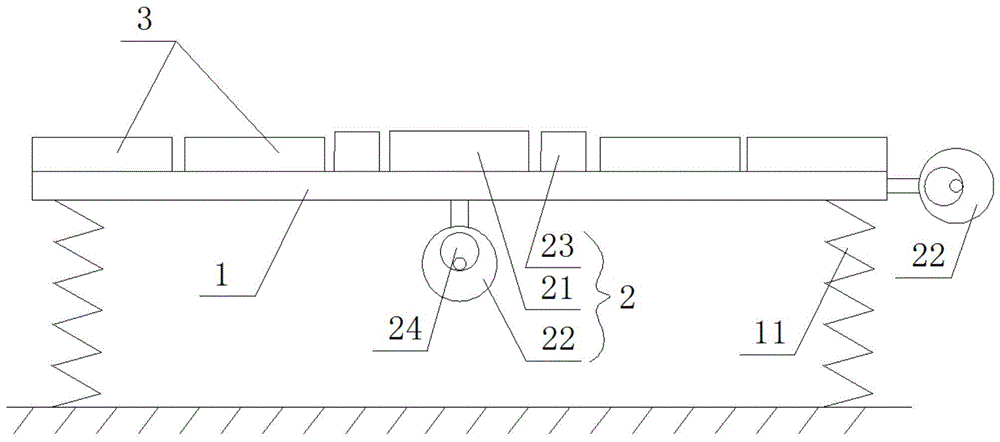
如图1-图10所示,一种线束接插件可靠性测试装置,包括测试主板1,测试主板1设置有振动装置2;As shown in FIG. 1-FIG. 10, a wiring harness connector reliability test device includes a
所述测试主板1上设置有至少两个测试模块3;At least two
测试模块3用于连接线束接插件检测其故障状态信息。The
本发明用于对整个线束接插件的故障进行检测,不判断线束接插件单根引线的故障。The present invention is used to detect the fault of the whole wiring harness connector, and does not judge the fault of a single lead wire of the wiring harness connector.
上述结构设置的效果为,关闭振动装置2时,该装置用于线束接插件的静态检测;开启振动装置2时,振动装置2驱动测试主板1振动,该装置用于线束接插件的动态检测;所述测试主板1上设置有多个测试模块3,将线束接插件的两端插在测试模块3的两个相应的插座上,测试模块3用于检测线束接插件是否存在断路、连接不良、引脚错位、引脚短路故障状态,如果有故障,则发出报警信息。The effect of the above structure setting is that when the
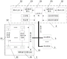
如图1所示,所述振动装置2包括主控单片机21和振动电机22,主控单片机21通过电机驱动模块23控制振动电机22转动;振动电机22的输出轴连接有振动机构。As shown in FIG. 1 , the
振动装置2还可以是振动电机22以及与振动电机22电阻调速电路或占空比调速电路。The
通过上述的结构设置主控单片机21通过电机驱动模块23控制振动电机22转动;振动电机22连接有振动机构,通过振动机构带动测试主板1振动,方便线束接插件的振动测试。Through the above structure, the main control single-
所述电机驱动模块23和振动电机22均为两个,其中一个振动电机22设置于测试主板1的底部,驱动测试主板1竖向振动,另一个振动电机22设置于测试主板1的侧面,驱动测试主板1水平振动,主控单片机21分别经电机驱动模块23与振动电机22连接。The
通过上述的结构,设置于测试主板1的底部的振动电机22主要控制测试主板1上下振动,设置于测试主板1侧面的振动电机22主要控制测试主板1水平振动。两个振动电机22施加振动的方向不一样,起到一个模拟上下振动和水平振动的效果。检测线速接插件在振动情况下的故障状态信息。如果只要一个振动电机22振动,可以通过设置开关控制电机驱动模块23通断电。Through the above structure, the
所述振动机构为固套在振动电机22输出轴上的偏心轮24。The vibration mechanism is an
采用偏心轮24作为振动机构结构简单,制造容易。Using the
所述测试主板1的底部设置有弹性支架11。该弹性支架为弹簧或橡胶垫。The bottom of the
采用弹性支架,使测试主板1随振动电机22的运转进行振动,振幅较大,大振幅测试效果较好。The elastic support is used to make the test
如图2、图5、图6所示,所述主控单片机21连接有启动键、停止键、振动频率旋钮以及振动时间旋钮。振动频率旋钮以及振动时间旋钮由可调电阻制成,输出可调电压信号给主控单片机21。As shown in FIG. 2 , FIG. 5 , and FIG. 6 , the
主控单片机21接收启动键的指令后,控制振动电机22振动;当主控单片机21接收停止键的指令后,控制振动电机22停止振动。主控单片机21接收振动频率旋钮的控制信号后,改变振动电机22的转速,从而调节振动机构的振动频率。主控单片机21接收振动时间旋钮的控制信号后,改变振动电机22的转动时间,从而调节振动机构的振动时间。时间到达时,振动电机22自动停转。After the
启动键、停止键、振动频率旋钮以及振动时间旋钮由用户手动调节。The start key, stop key, vibration frequency knob and vibration time knob are manually adjusted by the user.
如图2、图7-图10所示,所述测试模块3设置有测试单片机31,测试单片机31设置有第一测试端组,第一测试端组包括AD IN1端、AD IN2端、AD IN3端、AD IN4端、AD IN5端、ADIN6端,第一测试端组的测试端与第一线束插座32的插孔一一连接,第一线束插座32的插孔分别经上拉电阻R1~上拉电阻R6连接电源,测试单片机31设置有第二测试端组,第二测试端组包括AD OUT1端、AD OUT2端、AD OUT3端、AD OUT4端、AD OUT5端、AD OUT6端,第二测试端组的测试端与第二线束插座33的插孔一一连接,第二线束插座33的插孔分别经下拉电阻R7~下拉电阻R12接地,第一线束插座32的插孔和第二线束插座33的插孔一一对应;第一线束插座32的每一个插孔还分别经自动校准电路34连接第二线束插座33的对应插孔;测试单片机31设置有控制端组,控制端组包括AD CTRL1端、AD CTRL2端、AD CTRL3端、AD CTRL4端、AD CTRL5端、AD CTRL6端,该控制端组的相应控制端与自动校准电路34的控制端相连,控制自动校准电路34通断,自动校准电路34通断控制与其连接的第一线束插座32和第二线束插座33的对应插孔通断;As shown in FIG. 2, FIG. 7-FIG. 10, the
测试单片机31连接有正常指示灯LED2。The
第一线束插座32的插孔和第二线束插座33的插孔一一对应;线束接插件的一端插接在第一线束插座32上,另一端插接在第二线束插座33上,方便故障检测。The jacks of the
自动校准电路34的数量和第一线束插座32的插孔相同,并且一一对应,在测试单片机31上电时测试单片机31通过控制端组的相应控制端控制自动校准电路34导通,通过第一测试端组和第二测试端组采集第一线束插座32和第二线束插座33的对应插孔之间的参考电压,并进行保存;然后控制自动校准电路34全部断开;The number of the automatic calibration circuits 34 is the same as the jacks of the
用户将线束插接件的两端分别插在第一线束插座32和第二线束插座33上,即图8中的J2和J3,这时测试单片机31的第一测试端组和第二测试端组采集第一线束插座32和第二线束插座33的对应插孔之间的静态测试电压,如果静态测试电压和参考电压之间的差值全小于设置的误差阈值,则测试单片机31控制正常指示灯LED2点亮,否则,只要有一对对应插孔的静态测试电压和参考电压之间的差值大于设置的误差阈值,控制正常指示灯LED2熄灭。上述静态测试过程简单方便。The user inserts the two ends of the wiring harness connector into the first
其中上拉电阻的阻值各不相同,下拉电阻的阻值也各不相同,如图8所示,上拉电阻R1为910欧,上拉电阻R2为750欧,上拉电阻R3为560欧,上拉电阻R4为430欧,上拉电阻R5为270欧,上拉电阻R6为100欧,下拉电阻R7为100欧,下拉电阻R8为270欧,下拉电阻R9为430欧,下拉电阻R10为560欧,下拉电阻R11为750欧,下拉电阻R12为910欧,这样在线束接插件发生交叉故障时,其对应插孔的输出电压将发生改变。The resistance value of the pull-up resistor is different, and the resistance value of the pull-down resistor is also different. As shown in Figure 8, the pull-up resistor R1 is 910 ohms, the pull-up resistor R2 is 750 ohms, and the pull-up resistor R3 is 560 ohms. , the pull-up resistor R4 is 430 ohms, the pull-up resistor R5 is 270 ohms, the pull-up resistor R6 is 100 ohms, the pull-down resistor R7 is 100 ohms, the pull-down resistor R8 is 270 ohms, the pull-down resistor R9 is 430 ohms, and the pull-down resistor R10 is 560 ohms, the pull-down resistor R11 is 750 ohms, and the pull-down resistor R12 is 910 ohms, so when a cross fault occurs in the wiring harness connector, the output voltage of the corresponding jack will change.
如果需要进行动态测试,则需要将振动装置2开启,控制测试主板1振动,这时测试单片机31的第一测试端组和第二测试端组采集第一线束插座32和第二线束插座33的对应插孔之间的动态测试电压,测试单片机31检测如果动态测试电压和参考电压之间的差值全小于设置的误差阈值,则测试单片机31控制正常指示灯LED2点亮,否则,只要有一对对应插孔的动态测试电压和参考电压之间的差值大于设置的误差阈值,控制正常指示灯LED2熄灭。误差阈值可根据实际检测需要进行设定。If a dynamic test is required, the
所述自动校准电路34包括PNP开关管T1、NPN开关管T2以及场效应管Q1;PNP开关管T1的基极经电阻R22与测试单片机31的相应控制端相连AD CTRL1,PNP开关管T1的发射极连接电源,PNP开关管T1的发射极还经电阻R21连接PNP开关管T1的基极,PNP开关管T1的集电极经电阻R23连接场效应管Q1的栅极;The automatic calibration circuit 34 includes a PNP switch tube T1, an NPN switch tube T2 and a field effect tube Q1; The pole is connected to the power supply, the emitter of the PNP switch tube T1 is also connected to the base of the PNP switch tube T1 through the resistor R21, and the collector of the PNP switch tube T1 is connected to the gate of the field effect transistor Q1 through the resistor R23;
NPN开关管T2的基极经电阻R24连接测试单片机31的相应控制端ADThe base of the NPN switch tube T2 is connected to the corresponding control terminal AD of the
CTRL1,NPN开关管T2的集电极连接场效应管Q1的栅极,NPN开关管T2的发射极接地,场效应管Q1的栅极还经电容C21接地;CTRL1, the collector of the NPN switch transistor T2 is connected to the gate of the field effect transistor Q1, the emitter of the NPN switch transistor T2 is grounded, and the gate of the field effect transistor Q1 is also grounded through the capacitor C21;
场效应管Q1的漏极和源极分别与第一线束插座32和第二线束插座33的对应插孔相连。The drain electrode and the source electrode of the field effect transistor Q1 are respectively connected to the corresponding jacks of the first
PNP开关管T1、NPN开关管T2连接测试单片机31的相应控制端AD CTRL1为同一个。The PNP switch tube T1 and the NPN switch tube T2 are connected to the corresponding control terminal AD CTRL1 of the testing
通过上述的结构设置,当测试单片机31的相应控制端AD CTRL1输出高电平时,PNP开关管T1截止,NPN开关管T2导通,场效应管Q1关断;Through the above structural settings, when the corresponding control terminal AD CTRL1 of the
当测试单片机31的相应控制端AD CTRL1输出低电平时,PNP开关管T1导通,NPN开关管T2截止,场效应管Q1导通。When the corresponding control terminal AD CTRL1 of the
自动校准电路34的数量与第一线束插座32和第二线束插座33的插孔数量相同,自动校准电路34的结构相同。自动校准电路34为6个,结构相同,其余5个电路图略。The number of the automatic calibration circuits 34 is the same as that of the jacks of the
所述测试模块3还连接有模块编号设置电路35,测试模块3经通迅总线与主控单片机21相连向其发送故障状态信息。The
所述测试模块3设置有编码端组,编码端组包括NUM0端、NUM1端、NUM2端、NUM3端、NUM4端、NUM5端、NUM6端,编码端组连接有模块编号设置电路35。The
模块编号设置电路35用于设置测试模块3的编号,便于主控单片机21识别,测试模块3经通迅总线与主控单片机21相连向其发送故障状态信息;主控单片机21可将故障状态信息保存或经RS232接口传递到上位计算机进行显示和保存。The module
测试模块电路如图7-10所示,不同的线束插接件测试因为线束接口不同,所以测试模块3的第一线束插座32和第二线束插座33的插孔数量可以不同比如6个或10个,插孔尺寸大小也可以不相同。每个测试模块3上有:与主控单片机21相连的电源和通信接口,通过信接口采用串口TX端和RX端,与线束插接件相连的第一线束插座32和第二线束插座33图8中所示的线束接插件为6针插座、测试单片机31采用F310单片机,、自动校准电路34、模块编号设置电路35。模块编号设置电路35为一排电阻或者拨码开关,每个电阻焊接则对应0,不焊接对应1,拨码开关导通则对应0,断开则对应1,通过排列组合来进行编号,每个测试模块3的编号不同,例如图10中有7个电阻,通过排列组合有128种编号。The circuit of the test module is shown in Figure 7-10. The number of jacks of the
主控单片机21通过串口RX端以及TX端与数据总线连接。The
最后,需要注意的是:以上列举的仅是本发明的具体实施例子,当然本领域的技术人员可以对本发明进行改动和变型,倘若这些修改和变型属于本发明权利要求及其等同技术的范围之内,均应认为是本发明的保护范围。Finally, it should be noted that: the above enumeration is only the specific embodiment of the present invention, of course those skilled in the art can make changes and modifications to the present invention, if these modifications and modifications belong to the scope of the claims of the present invention and its equivalent technology within the scope of protection of the present invention.
Claims (7)
Priority Applications (1)
| Application Number | Priority Date | Filing Date | Title |
|---|---|---|---|
| CN201810699892.7A CN108828362B (en) | 2018-06-29 | 2018-06-29 | Wiring Harness Connector Reliability Test Device |
Applications Claiming Priority (1)
| Application Number | Priority Date | Filing Date | Title |
|---|---|---|---|
| CN201810699892.7A CN108828362B (en) | 2018-06-29 | 2018-06-29 | Wiring Harness Connector Reliability Test Device |
Publications (2)
| Publication Number | Publication Date |
|---|---|
| CN108828362A CN108828362A (en) | 2018-11-16 |
| CN108828362B true CN108828362B (en) | 2020-09-29 |
Family
ID=64134897
Family Applications (1)
| Application Number | Title | Priority Date | Filing Date |
|---|---|---|---|
| CN201810699892.7A Active CN108828362B (en) | 2018-06-29 | 2018-06-29 | Wiring Harness Connector Reliability Test Device |
Country Status (1)
| Country | Link |
|---|---|
| CN (1) | CN108828362B (en) |
Cited By (4)
| Publication number | Priority date | Publication date | Assignee | Title |
|---|---|---|---|---|
| US12413098B2 (en) | 2023-09-15 | 2025-09-09 | Lockheed Martin Corporation | Systems and methods for a charging cart of a wireless harness automated measurement system |
| US12498399B2 (en) | 2023-09-15 | 2025-12-16 | Lockheed Martin Corporation | Systems and methods for calibrating a wireless harness automated measurement system |
| US12578359B2 (en) | 2023-09-15 | 2026-03-17 | Lockheed Martin Corporation | Wireless harness automated measurement systems and methods |
| US12607668B2 (en) | 2023-09-15 | 2026-04-21 | Lockheed Martin Corporation | Systems and methods for wireless test modules of a wireless harness automated measurement system |
Families Citing this family (6)
| Publication number | Priority date | Publication date | Assignee | Title |
|---|---|---|---|---|
| TR202014132A2 (en) * | 2020-09-07 | 2020-11-23 | Elopar Elektrik Ve Otomotiv Parcalari Sanayi Ve Ticaret Anonim Sirketi | Last Observation Desk Navigation |
| CN114489018A (en) * | 2020-11-26 | 2022-05-13 | 重庆科凯前卫风电设备有限责任公司 | Fan system flexibility test platform and test method |
| CN112697456A (en) * | 2020-12-10 | 2021-04-23 | 奇瑞汽车股份有限公司 | Reliability test method for automobile circuit system |
| CN114323626A (en) * | 2022-01-17 | 2022-04-12 | 广东博力威科技股份有限公司 | Reliability testing device and method for connector |
| CN116184274A (en) * | 2023-04-25 | 2023-05-30 | 深圳市国威通电子技术有限公司 | High-voltage connector quality detection system and method |
| CN117630289A (en) * | 2023-11-27 | 2024-03-01 | 一汽解放汽车有限公司 | Fault detection device, system and method |
Family Cites Families (7)
| Publication number | Priority date | Publication date | Assignee | Title |
|---|---|---|---|---|
| US7696760B2 (en) * | 2007-11-30 | 2010-04-13 | Caterpillar Inc. | High voltage harness testing system |
| CN101464486A (en) * | 2009-01-15 | 2009-06-24 | 合肥工业大学 | Method of testing vehicle electric appliance system reliability |
| CN103364682B (en) * | 2013-06-28 | 2016-01-20 | 三一汽车制造有限公司 | A kind of Beam Detector, plant equipment |
| CN203909614U (en) * | 2014-06-10 | 2014-10-29 | 北汽福田汽车股份有限公司 | Wire harness connector for fault diagnosis of vehicle management system |
| CN206339353U (en) * | 2016-11-29 | 2017-07-18 | 北京汽车研究总院有限公司 | A kind of wire harness vibration test hit detection means |
| CN106949933B (en) * | 2017-04-07 | 2020-09-22 | 吉利汽车研究院(宁波)有限公司 | A kind of detection method of wiring harness connector |
| CN206832921U (en) * | 2017-06-13 | 2018-01-02 | 天津市捷威动力工业有限公司 | Module samples wire harness on off test frock |
-
2018
- 2018-06-29 CN CN201810699892.7A patent/CN108828362B/en active Active
Cited By (4)
| Publication number | Priority date | Publication date | Assignee | Title |
|---|---|---|---|---|
| US12413098B2 (en) | 2023-09-15 | 2025-09-09 | Lockheed Martin Corporation | Systems and methods for a charging cart of a wireless harness automated measurement system |
| US12498399B2 (en) | 2023-09-15 | 2025-12-16 | Lockheed Martin Corporation | Systems and methods for calibrating a wireless harness automated measurement system |
| US12578359B2 (en) | 2023-09-15 | 2026-03-17 | Lockheed Martin Corporation | Wireless harness automated measurement systems and methods |
| US12607668B2 (en) | 2023-09-15 | 2026-04-21 | Lockheed Martin Corporation | Systems and methods for wireless test modules of a wireless harness automated measurement system |
Also Published As
| Publication number | Publication date |
|---|---|
| CN108828362A (en) | 2018-11-16 |
Similar Documents
| Publication | Publication Date | Title |
|---|---|---|
| CN108828362B (en) | Wiring Harness Connector Reliability Test Device | |
| CN100549973C (en) | A USB bus interface detection device and detection method thereof | |
| CN102566567B (en) | Electronic control unit (ECU) sensor signal fault injection device for engine hardware in-the-loop simulation (HILS) system | |
| CN216748731U (en) | Detection circuit, interface link tooling plate and detection system | |
| CN103048581A (en) | Cable testing device | |
| CN112858786A (en) | Modular resistance voltage measuring device and method | |
| CN112731825B (en) | Detection circuit, device and detection method thereof | |
| CN111611118A (en) | Board self-check monitoring system, method and device | |
| CN202600084U (en) | Connecting line detector | |
| CN201569672U (en) | Auxiliary jig for testing wire rods | |
| CN219915827U (en) | Cable insulation testing device | |
| CN104459426A (en) | Cable detection system | |
| CN220438468U (en) | Battery simulation system | |
| CN115129522B (en) | A USB function pin detection system | |
| CN206863583U (en) | Signal supervisory instrument and system | |
| CN206892242U (en) | A kind of automative wiring failure detector | |
| CN115453311A (en) | Circuit board aging testing frame equipment | |
| CN205281252U (en) | A remote data transmission system for debugging of electric vehicle motor controller | |
| CN202048929U (en) | Digital measuring and verifying device | |
| CN203224587U (en) | Cable testing device | |
| CN206248760U (en) | PCB rosin joint joint welding automatic testing equipments | |
| CN209764982U (en) | connector plugging detection device and hardware-in-the-loop test equipment | |
| CN207516400U (en) | A kind of switch arrays and test device | |
| CN110887999B (en) | Train detector | |
| CN206833748U (en) | A kind of control unit for vehicle fault simulator |
Legal Events
| Date | Code | Title | Description |
|---|---|---|---|
| PB01 | Publication | ||
| PB01 | Publication | ||
| SE01 | Entry into force of request for substantive examination | ||
| SE01 | Entry into force of request for substantive examination | ||
| GR01 | Patent grant | ||
| GR01 | Patent grant | ||
| TR01 | Transfer of patent right |
Effective date of registration: 20241118 Address after: No. 1, Kang Chao Road, Banan District, Chongqing Patentee after: CHONGQING CITY HAOWEI MOTORCYCLE MANUFACTURE Co.,Ltd. Country or region after: China Address before: 400715 No. 2, natural road, Beibei District, Chongqing Patentee before: SOUTHWEST University Country or region before: China |
|
| TR01 | Transfer of patent right |