CN108771932B - Domestic dust removing device - Google Patents
Domestic dust removing device Download PDFInfo
- Publication number
- CN108771932B CN108771932B CN201810687365.4A CN201810687365A CN108771932B CN 108771932 B CN108771932 B CN 108771932B CN 201810687365 A CN201810687365 A CN 201810687365A CN 108771932 B CN108771932 B CN 108771932B
- Authority
- CN
- China
- Prior art keywords
- branch pipe
- pipe
- removing device
- dust removing
- water
- Prior art date
- Legal status (The legal status is an assumption and is not a legal conclusion. Google has not performed a legal analysis and makes no representation as to the accuracy of the status listed.)
- Expired - Fee Related
Links
- 239000000428 dust Substances 0.000 title claims abstract description 38
- XLYOFNOQVPJJNP-UHFFFAOYSA-N water Substances O XLYOFNOQVPJJNP-UHFFFAOYSA-N 0.000 claims abstract description 58
- 239000007921 spray Substances 0.000 claims description 16
- 238000010410 dusting Methods 0.000 claims 1
- 241001233242 Lontra Species 0.000 abstract description 6
- 238000004519 manufacturing process Methods 0.000 abstract description 3
- 239000003595 mist Substances 0.000 description 6
- 239000008399 tap water Substances 0.000 description 4
- 235000020679 tap water Nutrition 0.000 description 4
- 238000009434 installation Methods 0.000 description 3
- 230000009471 action Effects 0.000 description 2
- 238000010276 construction Methods 0.000 description 2
- 230000004048 modification Effects 0.000 description 2
- 238000012986 modification Methods 0.000 description 2
- 230000004075 alteration Effects 0.000 description 1
- 238000009435 building construction Methods 0.000 description 1
- 230000003749 cleanliness Effects 0.000 description 1
- 230000007547 defect Effects 0.000 description 1
- 230000000694 effects Effects 0.000 description 1
- 238000012423 maintenance Methods 0.000 description 1
- 230000001681 protective effect Effects 0.000 description 1
- 239000002351 wastewater Substances 0.000 description 1
Images

Classifications
-
- B—PERFORMING OPERATIONS; TRANSPORTING
- B01—PHYSICAL OR CHEMICAL PROCESSES OR APPARATUS IN GENERAL
- B01D—SEPARATION
- B01D47/00—Separating dispersed particles from gases, air or vapours by liquid as separating agent
- B01D47/06—Spray cleaning
Landscapes
- Chemical & Material Sciences (AREA)
- Chemical Kinetics & Catalysis (AREA)
- Nozzles (AREA)
- Separation Of Particles Using Liquids (AREA)
Abstract
The invention discloses a household dust removing device which comprises a lower shell and an upper shell, wherein a water pool and a water pump are arranged in the lower shell; the top of the upper shell is provided with an air outlet, and the lower part of the lower shell is provided with an air inlet; a fan and three screen plates are sequentially arranged in the upper shell from top to bottom, and the position of the screen plate at the lowest part is higher than the air inlet; the outlet pipeline of water pump is connected to a standpipe, corresponds three otter board punishment on the standpipe and is connected with a branch pipe respectively, and every branch pipe corresponds with an otter board respectively, and every branch pipe is connected with three atomizer respectively, and each atomizer passes corresponding otter board respectively downwards. The household dust removing device is low in manufacturing cost and small in occupied area; the operation does not need to adopt a filter element, and the operation cost is low.
Description
Technical Field
The invention relates to the technical field of environment-friendly equipment, in particular to a household dust removing device.
Background
Building construction can produce a large amount of dust, if the building site is nearer apart from the residential area, then the dust is in the room of resident of drifting about very easily, and the dust can seriously harm resident's healthy. In the prior art, dust is filtered mainly by a fresh air fan or an air purifier, so that the cleanliness of air is improved; however, since the distance from the construction site is short and the dust density is relatively large, the filter element of the new fan or the air purifier needs to be frequently replaced, and the running cost of the new fan or the air purifier is increased. There is therefore a need for a domestic dust removal device which is less expensive to operate.
It is seen that improvements and enhancements to the prior art are needed.
Disclosure of Invention
In view of the defects of the prior art, the invention aims to provide a household dust removing device, and aims to solve the technical problem that a fresh air fan or an air purifier in the prior art is high in operation cost when used for removing dust.
In order to achieve the purpose, the invention adopts the following technical scheme:
a household dust removing device comprises a lower shell and an upper shell which are detachably connected, wherein a water tank and a water pump are arranged inside the lower shell, a drain valve is arranged at the bottom of the water tank, the water tank is connected with a water inlet pipe, and the water inlet pipe is connected with a water inlet valve; the top of the upper shell is provided with an air outlet, and the lower part of the lower shell is provided with an air inlet; a fan and three screen plates are sequentially arranged in the upper shell from top to bottom, and the position of the screen plate at the lowest part is higher than the air inlet; the outlet pipeline of water pump is connected to a standpipe, corresponds three otter board punishment on the standpipe and is connected with a branch pipe respectively, and every branch pipe corresponds with an otter board respectively, and every branch pipe is connected with three atomizer respectively, and each atomizer passes corresponding otter board respectively downwards.
In the household dust removing device, the horizontal sections of the upper shell and the lower shell are both rectangular; the shape of each screen plate is rectangular, four gaskets are arranged on the inner wall of the upper shell corresponding to the four corners of each screen plate respectively, and each screen plate is connected with the corresponding four gaskets through screws.
In the household dust removing device, each screen plate is provided with 3 round holes, and each spray head penetrates through the corresponding round hole in an interference fit manner.
In the household dust removing device, each branch pipe comprises a first branch pipe connected with the vertical pipe and positioned outside the shell, a second branch pipe arranged on the corresponding screen plate and positioned in the shell, and a straight joint for connecting the first branch pipe and the second straight pipe; each spray head is arranged on the corresponding second branch pipe.
In the household dust removing device, an inlet end of each second branch pipe is provided with an internal thread, and a through hole is formed in the shell corresponding to the inlet end of each second branch pipe; the outlet end of each straight-through joint penetrates through a corresponding through hole on the shell and is screwed into the inlet end of a corresponding second straight pipe; the inlet end of each straight joint and the outlet end of the first branch pipe are respectively provided with a second external thread, and the inlet end of each straight joint and the outlet end of the corresponding first branch pipe are respectively connected through a nut.
In the household dust removing device, the water pump is arranged at the bottom in the shell, a drainage plate is arranged below the mesh plate positioned at the lowest part, and the bottom end of the drainage plate is positioned above the water pool.
Has the advantages that:
the invention provides a household dust removing device which is simple in overall structure, low in manufacturing cost and small in occupied area compared with the prior art. Because the running water is adopted to circulate to remove dust, a filter element is not needed, and the operation and maintenance cost is low. In addition, the operation is simple and convenient, the use is easy, and only the water inlet valve and the exhaust valve need to be operated when water is changed.
Drawings
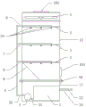
Fig. 1 is a front view of a household dust removing device provided by the present invention.
Fig. 2 is a schematic view of the connection between the first branch pipe and the second branch pipe in the household dust removing device provided by the invention.
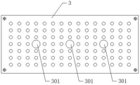
FIG. 3 is a top view of a net plate in the household dust removing device provided by the present invention.
Detailed Description
The invention provides a household dust removing device, and in order to make the purpose, technical scheme and effect of the invention clearer and clearer, the invention is further described in detail below by referring to the attached drawings and embodiments. It should be understood that the specific embodiments described herein are merely illustrative of the invention and are not intended to limit the invention.
Referring to fig. 1 to 3, the present invention provides a household dust removing device. The drawings are only for explaining the structural principle of the household dust removing device and are not to scale with the actual product.
The household dust removing device comprises a lower shell 11 and an upper shell 12 which are detachably connected, a water tank 2 and a water pump 5 are arranged inside the lower shell, an exhaust valve (not shown in the figure) is arranged at the bottom of the water tank, the water tank is connected with a water inlet pipe 21, and the water inlet pipe is connected with a water inlet valve 22; the top of the upper shell is provided with an air outlet 102, and the lower part of the lower shell is provided with an air inlet 101; a fan 4 and three screen plates 3 are sequentially arranged in the upper shell from top to bottom, and the position of the screen plate at the lowest part is higher than the air inlet; the inlet pipeline 51 of the water pump is connected to the water pool 2, the outlet pipeline 52 of the water pump is connected to a vertical pipe 60, the three corresponding screen plates on the vertical pipe are respectively connected with a branch pipe 7, each branch pipe 7 respectively corresponds to one screen plate 3, each branch pipe is respectively connected with three spray nozzles 79, and each spray nozzle 79 respectively downwards penetrates through the corresponding screen plate 3. The particular construction of the spray nozzle is not shown in the drawings since the spray nozzle itself is prior art. The upper and lower housings are preferably connected by a flange 19.
In use, the household dust removing device is placed indoors, and the water inlet pipe 21 is connected to a tap water pipe (not shown in the figure); the water inlet valve is opened to add tap water into the water pool, under the action of the water pump, the water in the water pool is pumped to each branch pipe and is sprayed out in a mist form from each spray nozzle, a large amount of water mist is diffused below each layer of spray nozzles, the water mist of each layer is gathered and falls down to form water flow, and finally the water flow returns to the water pool, so that circulation is formed. Under the action of the fan, air is sucked from the air inlet, sequentially passes through the 3 layers of water mist and is finally discharged from the air outlet; when air passes through each layer of water mist, the carried dust is combined with the water mist and finally falls into the water pool, so that the dust in the air is removed. After the water-saving device is used for a period of time, the waste water in the water tank is drained through the drain valve, and fresh tap water is replenished through the water inlet pipe.
Typically, the horizontal cross-sections of the upper and lower housings 13, 11 are both rectangular, i.e.: the household dust removing device is cuboid on the whole and occupies a small area; correspondingly, the shape of the mesh plate 3 is rectangular, four gaskets 38 (only one gasket is shown in fig. 2) are respectively arranged on the inner wall of the upper shell corresponding to the four corners of each mesh plate, and each mesh plate is connected with the corresponding four gaskets through screws 39. During actual installation, 3 net plates are connected with four corresponding gaskets through bolts from bottom to top in sequence.
As shown in fig. 3, further, in order to facilitate positioning of the spray heads, each mesh plate 3 is respectively provided with 3 circular holes 301, and each spray head passes through the corresponding circular hole in an interference fit manner; when the sprayer works normally, even if the water pressure in the sprayer is high, the sprayer can not move.
Further, in order to facilitate installation of the branch pipe, the following improvements can be made: each branch pipe 7 comprises a first branch pipe 71 connected with the vertical pipe and positioned outside the shell, a second branch pipe 72 arranged on the corresponding net plate and positioned in the shell, and a through joint 73 for connecting the first branch pipe and the second straight pipe; each spray head is arranged on the corresponding second branch pipe. That is, in actual assembly, each second branch pipe may be previously provided on the screen plate, and after the screen plate is disposed in the upper case, the second branch pipes are correspondingly previously provided in the case. Due to the interference fit between the spray head and the screen plate, the position of the second branch pipe is determined and cannot move relative to the screen plate.
As shown in fig. 3, preferably, the first branch pipe and the corresponding second branch pipe may be connected as follows: the inlet end (left end shown) of each second branch pipe 72 is provided with an internal thread, and the shell is provided with a through hole corresponding to the inlet end of each second branch pipe; the outlet end (shown as the right end) of each through joint 73 is provided with a first external thread, and the outlet end of each through joint respectively passes through a corresponding through hole on the shell and is screwed into the inlet end of a corresponding second straight pipe; the inlet end (shown as the right end) of each straight joint and the outlet end of the first branch pipe are respectively provided with second external threads, and the inlet end of each straight joint and the outlet end of the corresponding first branch pipe are respectively connected through a nut 74. In actual assembly, the outlet end of the through joint 74 is screwed into the inlet end of the corresponding second branch pipe 72, and the outlet end of the first branch pipe 71 and the inlet end of the through joint 73 are connected by the nut 74. By the arrangement, the first branch pipe and the second branch pipe can be quickly disassembled and assembled conveniently. In addition, in practical application, the main pipe, the first branch pipe, the through joint and the second branch pipe are preferably PVC pipes, so that the cost is low, the main pipe has better flexibility during installation, and the connection of the first branch pipe and the through joint is facilitated.
Further, the water pump 5 is arranged at the bottom in the shell, a drainage plate 8 is arranged below the mesh plate positioned at the lowest part, and the bottom end of the drainage plate is positioned above the water pool. The water pump is arranged in the lower shell body in the arrangement mode, and therefore the occupied area is saved. And through setting up the drainage plate, be convenient for lead rivers to flow smoothly in the pond.
Through the analysis, the household dust removing device provided by the invention mainly has the following advantages: (1) the whole structure is simple, the manufacturing cost is low, and the occupied area is small. (2) And tap water is adopted to circulate to remove dust, a filter element is not required, and the operation cost is low. (3) The operation is simple and convenient, the use is easy, and only the water inlet valve and the exhaust valve need to be operated when water is changed.
It should be understood that equivalents and modifications of the technical solution and inventive concept thereof may occur to those skilled in the art, and all such modifications and alterations should fall within the protective scope of the present invention.
Claims (5)
1. A household dust removing device comprises a lower shell and an upper shell which are detachably connected, and is characterized in that a water tank and a water pump are arranged inside the lower shell, a drain valve is arranged at the bottom of the water tank, the water tank is connected with a water inlet pipe, and the water inlet pipe is connected with a water inlet valve; the top of the upper shell is provided with an air outlet, and the lower part of the lower shell is provided with an air inlet; a fan and three screen plates are sequentially arranged in the upper shell from top to bottom, and the position of the screen plate at the lowest part is higher than the air inlet; an outlet pipeline of the water pump is connected to a vertical pipe, a branch pipe is connected to the position, corresponding to three screen plates, on the vertical pipe, each branch pipe corresponds to one screen plate, each branch pipe is connected with three spray nozzles, and each spray nozzle penetrates through the corresponding screen plate downwards; each screen plate is provided with 3 round holes, and each spray head penetrates through the corresponding round hole in an interference fit manner.
2. The household dust removing device as claimed in claim 1, wherein the horizontal cross-sections of the upper and lower housings are rectangular; the shape of each screen plate is rectangular, four gaskets are arranged on the inner wall of the upper shell corresponding to the four corners of each screen plate respectively, and each screen plate is connected with the corresponding four gaskets through screws.
3. The household dust removing device as claimed in claim 2, wherein each of the branch pipes comprises a first branch pipe connected to the vertical pipe and located outside the housing, a second branch pipe disposed on the corresponding mesh plate and located inside the housing, and a through joint for connecting the first branch pipe and the second straight pipe; each spray head is arranged on the corresponding second branch pipe.
4. A household dust removing device as claimed in claim 3, wherein the inlet end of each second branch pipe is provided with an internal thread, and the housing is provided with a through hole corresponding to the inlet end of each second branch pipe; the outlet end of each straight-through joint penetrates through a corresponding through hole on the shell and is screwed into the inlet end of a corresponding second straight pipe; the inlet end of each straight joint and the outlet end of the first branch pipe are respectively provided with a second external thread, and the inlet end of each straight joint and the outlet end of the corresponding first branch pipe are respectively connected through a nut.
5. A household dusting device according to claim 4 whereby the water pump is placed at the bottom of the housing and a flow guide plate is placed under the lowermost mesh plate and the bottom end of the flow guide plate is above the pool.
Priority Applications (1)
| Application Number | Priority Date | Filing Date | Title |
|---|---|---|---|
| CN201810687365.4A CN108771932B (en) | 2018-06-28 | 2018-06-28 | Domestic dust removing device |
Applications Claiming Priority (1)
| Application Number | Priority Date | Filing Date | Title |
|---|---|---|---|
| CN201810687365.4A CN108771932B (en) | 2018-06-28 | 2018-06-28 | Domestic dust removing device |
Publications (2)
| Publication Number | Publication Date |
|---|---|
| CN108771932A CN108771932A (en) | 2018-11-09 |
| CN108771932B true CN108771932B (en) | 2021-07-09 |
Family
ID=64030577
Family Applications (1)
| Application Number | Title | Priority Date | Filing Date |
|---|---|---|---|
| CN201810687365.4A Expired - Fee Related CN108771932B (en) | 2018-06-28 | 2018-06-28 | Domestic dust removing device |
Country Status (1)
| Country | Link |
|---|---|
| CN (1) | CN108771932B (en) |
Citations (5)
| Publication number | Priority date | Publication date | Assignee | Title |
|---|---|---|---|---|
| JPH11179144A (en) * | 1997-12-22 | 1999-07-06 | Ishikawajima Harima Heavy Ind Co Ltd | Spray type desulfurization apparatus |
| CN2844750Y (en) * | 2005-11-23 | 2006-12-06 | 颜小亮 | The room air cleaning machine |
| CN201101943Y (en) * | 2007-07-11 | 2008-08-20 | 云凤刚 | Spray column for multi-exhaust gas purification |
| CN201997258U (en) * | 2011-02-24 | 2011-10-05 | 中电投远达环保工程有限公司 | Smoke gas purifying device with one pump and plurality of spray nozzles |
| CN105964081A (en) * | 2016-06-24 | 2016-09-28 | 成都市沃发特科技有限公司 | Small-sized multilayer dust removal and desulfurization device |
-
2018
- 2018-06-28 CN CN201810687365.4A patent/CN108771932B/en not_active Expired - Fee Related
Patent Citations (5)
| Publication number | Priority date | Publication date | Assignee | Title |
|---|---|---|---|---|
| JPH11179144A (en) * | 1997-12-22 | 1999-07-06 | Ishikawajima Harima Heavy Ind Co Ltd | Spray type desulfurization apparatus |
| CN2844750Y (en) * | 2005-11-23 | 2006-12-06 | 颜小亮 | The room air cleaning machine |
| CN201101943Y (en) * | 2007-07-11 | 2008-08-20 | 云凤刚 | Spray column for multi-exhaust gas purification |
| CN201997258U (en) * | 2011-02-24 | 2011-10-05 | 中电投远达环保工程有限公司 | Smoke gas purifying device with one pump and plurality of spray nozzles |
| CN105964081A (en) * | 2016-06-24 | 2016-09-28 | 成都市沃发特科技有限公司 | Small-sized multilayer dust removal and desulfurization device |
Non-Patent Citations (1)
| Title |
|---|
| 脱硫喷淋管支撑件整体建模及设计改进;钟莎;《热能动力工程》;20160630;第31卷(第6期);第114-119页 * |
Also Published As
| Publication number | Publication date |
|---|---|
| CN108771932A (en) | 2018-11-09 |
Similar Documents
| Publication | Publication Date | Title |
|---|---|---|
| CN106076974A (en) | A kind of cleaning device of spare part in common use | |
| CN208553716U (en) | Purifying column spray equipment easy for installation | |
| CN206454424U (en) | A kind of horizontal taste removal equipment | |
| CN108771932B (en) | Domestic dust removing device | |
| CN211424583U (en) | Indoor cooling and humidifying system for spinning | |
| CN216223741U (en) | Acid-base spraying washing tower for industrial waste gas treatment | |
| CN109681938B (en) | Energy-saving invisible range hood with high cleaning rate and low noise | |
| CN207445882U (en) | For the Mobile dust collection device of tunnel hemi-closure space | |
| CN216465284U (en) | Concrete curing room | |
| CN209585731U (en) | A kind of artificial swimming pool automatic dust absorption system | |
| CN207214305U (en) | High-rise building intelligent fresh air purifier | |
| CN111603873A (en) | Rain-fog type and filter screen water film self-cleaning rain-type air purification device | |
| CN111829129A (en) | Ventilation equipment for building construction | |
| CN103639058B (en) | Water-storage self-cleaning type electrostatic filter with spraying and washing device | |
| CN206635922U (en) | A kind of family expenses remove the sewage water lifter of stink | |
| CN216457232U (en) | Installation structure of fire water pump suction pipe filter in pump house | |
| CN205860282U (en) | A kind of spray section of assembled air-conditioner | |
| CN219376515U (en) | Building engineering construction site sprays dust fall system | |
| CN216630209U (en) | Automatic dust collecting equipment of green construction usefulness | |
| CN218653673U (en) | Building device is built in energy-concerving and environment-protective type room | |
| CN214513528U (en) | Dust device for house building construction | |
| CN206997261U (en) | A kind of self-cleaning system for throwing humidity discharging sewage pipe | |
| CN215372771U (en) | Energy-saving wet film humidifier | |
| CN210482777U (en) | Green building roof | |
| CN210638210U (en) | A workplace for imitating bronze ware |
Legal Events
| Date | Code | Title | Description |
|---|---|---|---|
| PB01 | Publication | ||
| PB01 | Publication | ||
| SE01 | Entry into force of request for substantive examination | ||
| SE01 | Entry into force of request for substantive examination | ||
| GR01 | Patent grant | ||
| GR01 | Patent grant | ||
| CF01 | Termination of patent right due to non-payment of annual fee | ||
| CF01 | Termination of patent right due to non-payment of annual fee |
Granted publication date: 20210709 |