CN108701215B - System and method for identifying multi-object structures - Google Patents
System and method for identifying multi-object structures Download PDFInfo
- Publication number
- CN108701215B CN108701215B CN201780007367.8A CN201780007367A CN108701215B CN 108701215 B CN108701215 B CN 108701215B CN 201780007367 A CN201780007367 A CN 201780007367A CN 108701215 B CN108701215 B CN 108701215B
- Authority
- CN
- China
- Prior art keywords
- elements
- matrix
- input
- ink
- handwriting
- Prior art date
- Legal status (The legal status is an assumption and is not a legal conclusion. Google has not performed a legal analysis and makes no representation as to the accuracy of the status listed.)
- Active
Links
Images


Classifications
-
- G—PHYSICS
- G06—COMPUTING; CALCULATING OR COUNTING
- G06V—IMAGE OR VIDEO RECOGNITION OR UNDERSTANDING
- G06V30/00—Character recognition; Recognising digital ink; Document-oriented image-based pattern recognition
- G06V30/10—Character recognition
- G06V30/32—Digital ink
- G06V30/36—Matching; Classification
-
- G—PHYSICS
- G06—COMPUTING; CALCULATING OR COUNTING
- G06F—ELECTRIC DIGITAL DATA PROCESSING
- G06F3/00—Input arrangements for transferring data to be processed into a form capable of being handled by the computer; Output arrangements for transferring data from processing unit to output unit, e.g. interface arrangements
- G06F3/01—Input arrangements or combined input and output arrangements for interaction between user and computer
- G06F3/048—Interaction techniques based on graphical user interfaces [GUI]
- G06F3/0487—Interaction techniques based on graphical user interfaces [GUI] using specific features provided by the input device, e.g. functions controlled by the rotation of a mouse with dual sensing arrangements, or of the nature of the input device, e.g. tap gestures based on pressure sensed by a digitiser
- G06F3/0488—Interaction techniques based on graphical user interfaces [GUI] using specific features provided by the input device, e.g. functions controlled by the rotation of a mouse with dual sensing arrangements, or of the nature of the input device, e.g. tap gestures based on pressure sensed by a digitiser using a touch-screen or digitiser, e.g. input of commands through traced gestures
- G06F3/04883—Interaction techniques based on graphical user interfaces [GUI] using specific features provided by the input device, e.g. functions controlled by the rotation of a mouse with dual sensing arrangements, or of the nature of the input device, e.g. tap gestures based on pressure sensed by a digitiser using a touch-screen or digitiser, e.g. input of commands through traced gestures for inputting data by handwriting, e.g. gesture or text
-
- G—PHYSICS
- G06—COMPUTING; CALCULATING OR COUNTING
- G06F—ELECTRIC DIGITAL DATA PROCESSING
- G06F40/00—Handling natural language data
- G06F40/10—Text processing
- G06F40/166—Editing, e.g. inserting or deleting
- G06F40/171—Editing, e.g. inserting or deleting by use of digital ink
-
- G—PHYSICS
- G06—COMPUTING; CALCULATING OR COUNTING
- G06V—IMAGE OR VIDEO RECOGNITION OR UNDERSTANDING
- G06V30/00—Character recognition; Recognising digital ink; Document-oriented image-based pattern recognition
- G06V30/10—Character recognition
- G06V30/22—Character recognition characterised by the type of writing
-
- G—PHYSICS
- G06—COMPUTING; CALCULATING OR COUNTING
- G06V—IMAGE OR VIDEO RECOGNITION OR UNDERSTANDING
- G06V30/00—Character recognition; Recognising digital ink; Document-oriented image-based pattern recognition
- G06V30/10—Character recognition
- G06V30/26—Techniques for post-processing, e.g. correcting the recognition result
- G06V30/262—Techniques for post-processing, e.g. correcting the recognition result using context analysis, e.g. lexical, syntactic or semantic context
- G06V30/268—Lexical context
-
- G—PHYSICS
- G06—COMPUTING; CALCULATING OR COUNTING
- G06V—IMAGE OR VIDEO RECOGNITION OR UNDERSTANDING
- G06V30/00—Character recognition; Recognising digital ink; Document-oriented image-based pattern recognition
- G06V30/10—Character recognition
- G06V30/26—Techniques for post-processing, e.g. correcting the recognition result
- G06V30/262—Techniques for post-processing, e.g. correcting the recognition result using context analysis, e.g. lexical, syntactic or semantic context
- G06V30/274—Syntactic or semantic context, e.g. balancing
-
- G—PHYSICS
- G06—COMPUTING; CALCULATING OR COUNTING
- G06V—IMAGE OR VIDEO RECOGNITION OR UNDERSTANDING
- G06V30/00—Character recognition; Recognising digital ink; Document-oriented image-based pattern recognition
- G06V30/40—Document-oriented image-based pattern recognition
- G06V30/41—Analysis of document content
- G06V30/412—Layout analysis of documents structured with printed lines or input boxes, e.g. business forms or tables
Abstract
A system, method and computer program for identifying an arrangement of a plurality of objects on a computing device. The computing device may include: a processor; and at least one non-transitory computer readable medium for recognizing handwriting input under control of the processor. The non-transitory computer readable medium may be configured to: determining, using the medium, at least one geometric relationship between the plurality of input identifying elements; and assigning, with the medium, the identification elements having the at least one geometric relationship therebetween to corresponding locations in the arrangement of identification elements. The location of the arrangement may be a cell in a two-dimensional structure of the identification elements. The at least one geometric relationship may be that the plurality of identification elements overlap in one or more directions in the arrangement.
Description
Technical Field
The present description relates generally to the field of using a computing device to recognize inputs of multiple handwritten objects within a structure. The present specification more specifically relates to detecting a two-dimensional structure of handwritten content by considering a positional relationship of input content and handwriting recognition of the input content.
Background
Computing devices are becoming increasingly common in everyday life. They take the following form: desktop computers, laptop computers, tablet computers, hybrid computers (2 in 1), electronic book readers, mobile phones, smart phones, wearable computers (including smart watches, smart glasses/headsets), Global Positioning System (GPS) units, Enterprise Digital Assistants (EDAs), Personal Digital Assistants (PDAs), game consoles, and the like. In addition, computing devices are included in vehicles and devices, such as automobiles, trucks, farm equipment, manufacturing equipment, building environmental controls (e.g., lighting, HVAC), and household and commercial appliances.
A computing device typically consists of at least one processing element, such as a Central Processing Unit (CPU), some form of memory, and output devices. Various computing devices and their subsequent use require various interfaces and input devices. One such input device is a touch-sensitive surface (e.g., a touchscreen or touchpad) in which user input is received through contact between a user's finger or an instrument (e.g., a pen or stylus) and the touch-sensitive surface. Another input device is an input surface that senses gestures made by a user on the input surface. Another input device is a position detection system that detects the relative position of a touch or non-touch interaction with a non-touch physical or virtual surface. Any of these input methods may be generally used for drawing or inputting text. The user's handwriting is interpreted using a handwriting recognition system or method. Other systems for handwriting input on a computing device include electronic or digital pens that interact with paper, coded or digitized surfaces to move them relative to the surface and are tracked by the computing device (e.g., systems provided by Anoto ab., Leapfrog corporation, and livescript corporation).
Regardless of the input method used, handwriting recognition systems and methods generally involve determining the beginning of a digital ink stroke (e.g., when a first contact is made with a touch-sensitive surface (a pen-down event)); termination of a stroke (e.g., when contact with the touch-sensitive surface ends (pen-up event)); and any movement (gesture or stroke) made between the start and the end of the stroke. These determined strokes are processed to recognize and interpret the input. The type of computing device or input surface may also determine the type of handwriting recognition system or method used. For example, if the input surface is large enough (such as a tablet), the user may enter handwriting anywhere on or above the input surface as if the user were writing on paper. However, this increases the complexity of the recognition task, as the individual elements to be recognized may or may not be related to the relative positions of the elements.
For example, for structured content (e.g., mathematical equations, tables, and matrices), the relative positioning of handwritten elements is necessary to define the structure. Some systems may be used to process identification of mathematical matrices, for example, U.S. patent nos. 7,447,360 and 8,121,412. These systems rely on an indication element for identification (such as, for example, brackets or spatial alignment within rows and columns) and therefore identify only the structure without regard to the content itself. While such identifications are applicable to relatively simple and well-formed matrices, they cannot handle more complex matrices (e.g., matrices containing complex elements such as equations, sub-matrices, misaligned matrix elements, or having empty element cells (e.g., row and column locations)). In addition, the systems of these patents provide absolute identification of these structures, thereby affecting the identification of the content itself.
There is a need for a system that recognizes matrices and similar complex content structures that do not rely on the input of specific designated elements or gestures and that does not significantly increase the processing time or complexity of recognizing them while retaining sufficient recognition accuracy.
Disclosure of Invention
In the following, examples of the invention described herein provide a system and method for providing a system for identifying an arrangement of a plurality of objects on a computing device. In one example, a computing device may include: a processor; and at least one non-transitory computer readable medium for recognizing handwriting input under control of the processor. The non-transitory computer readable medium may be configured to: determining, using the medium, at least one geometric relationship between the plurality of input identifying elements; and assigning, with the medium, the identification elements having the at least one geometric relationship therebetween to corresponding locations in the arrangement of identification elements. The location of the arrangement may be a cell in a two-dimensional structure of the identification elements. The at least one geometric relationship may be that the plurality of identification elements overlap in one or more directions in the arrangement.
The at least one non-transitory computer-readable medium may be further configured to: the overlap is determined based on a comparison of a directed distance between one or more geometric features of the plurality of identified elements to at least one geometric threshold. The at least one geometric threshold may be based on at least one geometric spacing of at least some of the identified elements. The at least one geometrical spacing may also be a maximum spacing between components of at least some of the identification elements.
In another example, the invention includes a method for identifying an arrangement of a plurality of objects on a computing device. Each computing device may include: a processor; and at least one non-transitory computer readable medium for recognizing handwriting input under control of the processor. The method may comprise the steps of: (i) determining, with the medium, at least one geometric relationship between the input plurality of identification elements, and (ii) assigning, with the medium, the identification elements having the at least one geometric relationship therebetween to corresponding locations in the arrangement of identification elements. The location of the arrangement may be a cell in a two-dimensional structure of the identification elements. The at least one geometric relationship may be that the plurality of identification elements overlap in one or more directions in the arrangement.
The method may further comprise the steps of: the overlap is determined based on a comparison of a directed distance between one or more geometric features of the plurality of identified elements to at least one geometric threshold. The at least one geometric threshold may be based on at least one geometric spacing of at least some of the identification elements. The at least one geometric spacing may also be a maximum spacing between components of at least some of the identification elements.
In another example, the disclosure includes a non-transitory computer-readable medium having computer-readable program code embodied therein. The computer readable program code may be adapted to be executed to implement a method for identifying an arrangement of a plurality of objects input to a computing device. The computing device may include: a processor; and at least one system non-transitory computer readable medium for recognizing handwriting input under control of the processor. The method comprises the following steps: (i) determining, with the medium, at least one geometric relationship between the input plurality of identification elements, and (ii) assigning, with the medium, the identification elements having the at least one geometric relationship therebetween to corresponding locations in the arrangement of identification elements. The location of the arrangement may be a cell in a two-dimensional structure of the identification elements. The at least one geometric relationship may be that the plurality of identification elements overlap in one or more directions in the arrangement.
The method may further comprise the steps of: the overlap is determined based on a comparison of a directed distance between one or more geometric features of the plurality of identified elements to at least one geometric threshold. The at least one geometric threshold may be based on at least one geometric spacing of at least some of the identified elements. The at least one geometric spacing may also be a maximum spacing between components of at least some of the identification elements.
Drawings
The present systems and methods will be more fully understood from the following detailed description of examples thereof, taken together with the accompanying drawings. In the drawings, like reference numerals designate like elements. In the drawings:
FIG. 1 illustrates a block diagram of a computing device in accordance with examples of the present systems and methods;
FIG. 2 illustrates a block diagram of an example handwriting recognition system in accordance with the present systems and methods;
FIG. 3 shows a block diagram illustrating details of the handwriting recognition system of FIG. 2, in accordance with examples of the present systems and methods;
FIG. 4A illustrates an example of handwriting input in a 2 x 2 matrix in accordance with the present system;
FIG. 4B illustrates an example of a recognition output of the handwriting input of FIG. 4A.
FIG. 5A illustrates an example of handwriting input in a 2 x 3 matrix in accordance with the present system;
FIG. 5B illustrates an example of a recognition output of the handwriting input of FIG. 5A.
Fig. 6 shows an example of handwriting input in the form of a 2 x 2 matrix according to the present system.
Fig. 7 shows an example of handwriting input in the form of a 2 x 2 matrix according to the present system.
Fig. 8 shows an example of handwriting input in the form of a 4 x 4 matrix according to the present system.
Fig. 9 shows an example of handwriting input in the form of a 2 x 3 matrix according to the present system.
Fig. 10 shows an example of handwriting input in the form of a 2 x 2 matrix according to the present system.
Fig. 11A shows an example of handwriting input in the form of a 3 x 3 matrix according to the present system.
Fig. 11B illustrates an example of a recognition output of the handwriting input of fig. 11A.
Fig. 12 shows an example of handwriting input in the form of a 3 x 3 matrix according to the present system.
Fig. 13 shows an example of handwriting input according to the present system.
Fig. 14A shows another example of handwriting input according to the present system.
Fig. 14B shows an example of a recognition output of the handwriting input of fig. 14A.
Fig. 15 shows yet another example of handwriting input according to the present system.
FIG. 16 shows an example of handwriting input in the form of a 3 x 3 matrix with nested matrices in accordance with the present system.
Fig. 17 shows an example of handwriting input in the form of a 1 x 3 matrix according to the present system.
Fig. 18 shows an example of handwriting input in the form of a 3 x 1 matrix according to the present system.
Fig. 19 shows an example of handwriting input according to the present system.
Fig. 20 shows an example of handwriting input according to the present system.
Fig. 21 to 31 show examples of matrix identification according to the present system.
Detailed Description
In the following detailed description, numerous specific details are set forth by way of examples in order to provide a thorough understanding of the relevant teachings. It will be apparent, however, to one of ordinary skill in the art that the present teachings may be practiced without these specific details. In other instances, well known methods, procedures, components, and/or circuits have been described at a relatively high-level, without detail, in order to avoid unnecessarily obscuring aspects of the present teachings. References and discussions of directional features (e.g., up, down, above, below, lowest, highest, horizontal, vertical, etc.) are made with respect to a cartesian coordinate system as applied to an input surface on which an input to be recognized is made.
Various technologies described herein are generally directed to capturing, processing, and managing hand-drawn and hand-written content on portable and non-portable computing devices in a manner that allows the content to be converted into a faithful typeset or beautified version while preserving the style of the input content. The systems and methods described herein may recognize natural writing and drawing styles of a user input to a computing device via an input surface (e.g., a touch sensitive screen) connected to or in the computing device, or via an input device (e.g., a digital pen or mouse) connected to the computing device, or via a physical or virtual surface monitored by a position detection system. Although various examples have been described with respect to recognizing handwritten input using so-called online recognition techniques, it should be understood that other forms of input recognition may be applied, such as offline recognition that recognizes images rather than digital ink. The terms hand-drawing and handwriting are used interchangeably herein to define digital content that a user manipulates directly on digital media or digitally connected media using his/her hands or created via an input tool, such as a hand-held stylus. The term "hand" is used herein to provide a brief description of the input technique, however, the use of other parts of the user's body (e.g., feet, mouth, and eyes) for similar inputs is also included in this definition.
Fig. 1 illustrates a block diagram of an example computing device 100. The computing device may be a desktop computer, a laptop computer, a tablet computer, an e-book reader, a mobile phone, a smartphone, a wearable computer, a digital watch, an interactive whiteboard, a Global Positioning System (GPS) unit, an Enterprise Digital Assistant (EDA), a Personal Digital Assistant (PDA), a gaming console, and so forth. The computing device 100 includes the following components: at least one processing element, some form of memory, and input and/or output (I/O) devices. These components communicate with each other through inputs and outputs implemented, for example, by connectors, lines, buses, cables, buffers, electromagnetic links, networks, modems, transducers, IR ports, antennas, or other devices known to those of ordinary skill in the art.
The illustrated example of a computing device 100 has at least one display 102 for outputting data (e.g., images, text, and video) from the computing device. The display 102 may use LCD, plasma, LED, iOLED, CRT or any other suitable technology known to those of ordinary skill in the art to be touch sensitive or non-touch sensitive. At least some of the displays 102 are co-located with at least one of the input surfaces 104. The input surface 104 may employ the following techniques to receive user input: such as resistive, surface acoustic wave, capacitive, infrared grid, infrared acrylic projection, optical imaging, dispersive signal technology, acoustic pulse recognition, or any other suitable technology known to one of ordinary skill in the art. The input surface 104 may be bounded by a permanent or video-generated boundary that clearly identifies its boundaries. Alternatively or additionally to an in-vehicle display, computing device 100 may have projection display capabilities. Alternatively, the computing device may include an input surface that is separate from or without a display. In the case of a device without a display, inputs made via the input surface are not displayed by the computing device, but rather the device is used only as an input device, recognized inputs (discussed later) being used, for example, for control inputs, or displayed as content on a connected device or a dedicated display device.
The computing device 100 also includes a processor 106, the processor 106 being a hardware device for executing software, particularly software stored in the memory 108. The processor may be any custom made or commercially available general purpose processor, Central Processing Unit (CPU), a commercially available microprocessor including a semiconductor based microprocessor (in the form of a microchip or chip set), a microcontroller, a Digital Signal Processor (DSP), an Application Specific Integrated Circuit (ASIC), a Field Programmable Gate Array (FPGA) or other programmable logic device, discrete gate or transistor logic, discrete hardware components, a state machine, or any combination of software instructions designed to perform as is known to one of ordinary skill in the art.
The memory 108 may include any one or combination of the following: volatile memory elements (e.g., random access memory (RAM, such as DRAM, SRAM, or SDRAM) and non-volatile memory elements (e.g., ROM, EPROM, flash PROM, EEPROM, a hard disk, a magnetic or optical disk, storage registers, CD-ROM, WORM, DVD, a Redundant Array of Inexpensive Disks (RAID), another Direct Access Storage Device (DASD), or any other magnetic, resistive, or phase-change non-volatile memory.) furthermore, memory 108 may comprise an electronic, magnetic, optical, and/or other type of storage media. memory 108 may have a distributed architecture in which various components are remote from one another but still accessible to processor 106. furthermore, memory 108 may be remote from the device (e.g., at a server or cloud-based system), but memory 108 may be remotely accessible by computing device 100. memory 108 is coupled to processor 106, the processor 106 can read information from the memory 108 and write information to the memory 108. In the alternative, the memory 108 may be integral to the processor 106. In another example, both the processor 106 and the memory 108 may reside in a single ASIC or other integrated circuit.
The software in memory 108 includes an operating system 110, an application 112 in the form of a non-transitory computer-readable medium having computer-readable program code embodied therein, and a handwriting recognition (HWR) system 114, which may each include one or more ofSeparate computer programs, each having an ordered listing of executable instructions for implementing logical functions. The operating system 110 controls the execution of applications 112 and the HWR system 114. The operating system 110 may be any proprietary operating system or commercially or freely available operating system, such as WEBOS, MAC and
 LINUX and ANDROID. It should be understood that other operating systems may be utilized. Alternatively, the
 application 112 of the present system and method may be provided without the use of an operating system.
The application 112 may be associated with handwriting recognition, different functionality, or both as described herein. Applications 112 include programs that are provided with computing device 100 at the time of manufacture, and may also include programs that are uploaded to or downloaded into computing device 100 after manufacture. Some examples include text editors, telephone dialers, contact directories, instant messaging facilities, computer-aided design (CAD) programs, email programs, word processing programs, web browsers, and cameras.
The HWR system 114 with support and compatibility capabilities may be a source program, executable program (object code), script, application, or any other entity having a set of instructions to be executed. In the case of a source program, the program needs to be translated via a compiler, assembler, interpreter, or the like, which may or may not be included within the memory, in order to operate properly in conjunction with the operating system. Further, a handwriting recognition system with support and compatibility capabilities can be written as: (a) an object-oriented programming language having classes of data and methods; (b) program programming languages having routines, subroutines, and/or functions, such as, but not limited to, C, C + +, Pascal, Basic, Fortran, Cobol, Perl, Java, Objective C, Swift, and Ada; or (c) a functional programming language such as, but not limited to, Hope, Rex, Common Lisp, Scheme, Clojere, Racket, Erlang, OCamll, Haskell, Prolog, and F #. Alternatively, the HWR system 114 may be a method and system for communicating with a handwriting recognition system that is remote from the device (e.g., at a server or cloud-based system), but may be accessed remotely by the computing device 100 over a communication link using the aforementioned communication I/O devices of the computing device 100. Further, the application 112 and the HWR system 114 may operate together or be combined into a single application. Further, the application 112 and/or the HWR system 114 may be integrated within the operating system 110.
Strokes entered on the input surface 104 or via the input surface 104 are processed by the processor 106 into digital ink. A user may input strokes with a finger or some other tool suitable for use with an input surface, such as a pen or stylus. If techniques are being used that sense motion near the input surface 104, the user may also enter strokes by making gestures above the input surface 104, or using a peripheral device of the computing device 100 (e.g., a mouse or joystick). A stroke is characterized by at least a stroke start position, a stroke end position, and a path connecting the stroke start position and the stroke end position as captured by the application 112 and/or HWE system 14. Other information (e.g., timing, pressure, angle at multiple sampling points along the path) may also be captured to provide further details of the stroke. Since different users naturally write the same object (e.g., letters, shapes, or symbols) with slight variations, the present system accommodates various ways in which each object may be identified as the correct or intended object while being input.
Fig. 2 is a schematic diagram of an example of the HWR system 114. The HWR system 114 includes stages such as preprocessing 116, recognition 118, and output 120. The pre-processing stage 116 processes the digital ink to achieve greater accuracy and reduce processing time during the recognition stage 118. The pre-processing may include: the path connecting the stroke start position and the stroke end position is normalized by applying size normalization and/or a method such as B-spline approximation to smooth the input. The pre-processed strokes are then passed to the recognition stage 118, and the recognition stage 118 processes the pre-processed strokes to recognize the objects formed thereby. The identified objects, which are typically displayed as a typographical version of the handwritten elements/characters, are then output 120 to the display 102.
The identification stage 118 may include different processing elements or experts. Fig. 3 is a schematic illustration of the example of fig. 2 showing schematic details of the recognition stage 118. Three experts, segmentation expert 122, recognition expert 124, and language expert 126, are shown, which cooperate through dynamic programming to produce output 120.
The segmentation expert 122 defines different ways to segment the input stroke into various element hypotheses (e.g., alphanumeric characters and mathematical operators, text characters, various shapes or sub-expressions) to form a representation (e.g., a mathematical equation, word, or group of shapes). For example, the segmentation expert 122 may form element hypotheses by grouping consecutive strokes of the original input to obtain a segmentation graph in which each node corresponds to at least one element hypothesis and adjacency constraints between the elements are handled by node connection.
The recognition expert 124 provides a classification of the features extracted by the classifier 128 and outputs a list of element candidates with probabilities or recognition scores for each node of the segmentation graph. There are many types of classifiers that can be used to solve this recognition task, such as support vector machines, hidden markov models, or neural networks (e.g., multilayer perceptrons, deep convolutional or recurrent neural networks). The choice depends on the complexity, accuracy and speed required for the task.
The language expert 126 uses a language model (e.g., grammar or semantics) to generate linguistic meanings for different paths in the segmentation graph. The expert 126 examines the candidates suggested by other experts based on the linguistic information 130. Linguistic information 130 may include a thesaurus, regular expressions, etc., and is a store of all static data used by linguistic experts 126 to execute the language model. The language model may rely on statistical information about a given language. Linguistic information 130 is adaptively or non-adaptively computed offline based on the results of the recognition and user interaction and is provided to linguistic experts 126. The linguistic experts 126 aim to find the optimal recognition path. In one example, the linguistic experts 126 accomplish this by exploring a language model, such as a Final State Automaton (FSA) that represents the contents of the linguistic information 130. In addition to the thesaurus constraints, the linguistic expert 126 may also use a language model modeled with statistical information to determine how often a given sequence of elements appears in a given language or is used by a particular user to evaluate the linguistic likelihood of interpretation of a given path of a segmentation graph.
The systems and methods described herein utilize the HWR system 114 to recognize handwritten input to the device 100. In particular, the present systems and methods identify content input within a structure (e.g., a matrix). A matrix is defined herein as a layout of several elements that are typically related, typically numbers, characters, symbols, mathematical expressions in one or more rows and columns, but without the use of row and/or column indicators (e.g., lines and headings that may exist in a table, or points and numbers that may exist in a list). Such matrices are typically used in mathematical operations and may be input by one or more users of device 100 to capture information and/or perform such operations, for example, to provide mathematical solutions (discussed later), either manually through handwriting processing or automatically through the capabilities of application 112.
Unlike the previously discussed known systems for identifying structured input (e.g., matrices), the present systems and methods do not require the user to enter specific content (e.g., parentheses) to effect the identification, nor do they use a process that does not identify matrices with more complex elements (e.g., equations, sub-matrices, unaligned elements, and missing elements). Furthermore, known systems use geometric projections to detect rows and columns and only process the entire structure for identification, while the present system and method may use incremental identification and geometric relationships of all elements without projections. These and other features of the present system and method will now be discussed.
Fig. 4-20 illustrate various examples of handwriting or freehand matrices, some of which are also shown in typeset form. FIG. 4A illustrates a handwritten input that has been made on the input surface 104 of the device 100, for example, in the form of a 2 by 2 (or 2 x 2; the standard usage of "row number" x "column number" is used herein) digital ink matrix 400. The matrix 400 has four content elements, where 402 is "3", 404 is "2", 406 is "7", and 408 is "1". The elements 402 and 404 are located in a first generally horizontal row 410, the elements 406 and 408 are located in a second generally horizontal row 412, the elements 402 and 406 are located in a first generally vertical column 414, and the elements 404 and 408 are located in a second generally vertical column 416. These content elements are contained within a first generally vertical bracket or fence (spring) element 418 (e.g., on the left hand side of the first column 414) and a second generally vertical bracket or fence element 420 (e.g., on the right hand side of the second column 414). The relative position of the content elements in the one or more rows and the one or more columns provides a first characteristic of the matrix 400 based on at least one geometric relationship of the input identification elements, and the inclusion of the content elements within the one or more fence elements provides a second characteristic of the matrix 400.
The application 112 of the present systems and methods detects the first characteristic, either alone or in conjunction with the second characteristic (related to the handwriting recognition performed by the HWR system 114) to determine that the input 400 is a matrix, and outputs a typesetting matrix 400' using a predetermined and/or user-settable formatting (e.g., via a user interface UI on the device 100), as shown in fig. 4B. As can be seen, the composition matrix 400 ' has corresponding composition versions 402 ' through 408 ' of the digital ink content elements 402 through 408 and corresponding composition versions 418 ' and 420 ' of the digital ink fence elements 418 and 420, the elements 402 ' through 408 ' still being arranged in the rows 410, 412 and columns 414, 416. Thus, for example, the present system and method displays the identified matrix 400 in the format expected by the user for the digital version of the matrix. It will be appreciated that the display format of the identified matrix may be different and may not necessarily be "typeset ink", but "beautify" digital ink; that is, the display of digital ink is preserved, but the natural variations of the handwriting are softened or normalized by modifying the relative positions of the elements, smoothing and/or normalizing the ink elements (e.g., the characters themselves, etc.). Whether in digital ink or typeset ink (or both) for beautification (e.g., aligning the relative positions of matrix elements), feedback may be provided to the user regarding the recognition of the matrix and its contents, e.g., by previewing the recognition results or its elements, e.g., showing brackets (as not yet entered).
The input of fig. 4 is a relatively simple example of a matrix with single digit numbers as elements of the content in good alignment with rows and columns, and a relatively clear fence around the content. FIG. 5A shows a similar simple 2X 3 matrix of digital ink rendered from handwritten input, but with alphabetic content elements. FIG. 5B illustrates the recognition output of the present system and method for typesetting matrices. Similar to fig. 4, the input of fig. 5 is a relatively simple example of a matrix with single alphabetic characters as elements of the content in relatively good alignment with rows and columns, and a relatively clear fence around the content. Fig. 6 shows a similar simple 2 x 2 digital ink matrix presented from handwritten input, with single-digit numbers as content elements relatively well aligned with rows and columns, but the content is surrounded or contained by differently shaped fence elements (e.g., using parentheses instead of square brackets). The present system and method is configured to identify these different and other fence forms to help detect matrix inputs. It should be noted that while the fence elements are secondary characteristics of the matrix, other structures having primary characteristics of content in rows and/or columns have similar secondary characteristics (e.g., vertical and/or horizontal lines drawn in a table). Furthermore, it may be sufficient to identify the first characteristic of the input matrix alone, i.e. without taking into account the second characteristic (e.g. even fence elements may not be present), for such detection, as will be described in detail later.
A somewhat more complex example of a handwriting matrix is shown in fig. 7, where the input 2 x 2 matrix has double-digit numbers as content elements, at least one column being a slightly misaligned column (e.g. the left-hand column). This slight misalignment, along with the spacing between digits in each double-digit element, presents a challenge to correctly identify that the matrix is a 2 x 2 matrix, since one or more spacings may be considered to be spacings between columns rather than between constituent parts of double digits, so it is contemplated that, without robust identification rules, the matrix of fig. 7 may be detected as a 2 x 5 matrix of single-digit elements (e.g., "1" and "2" in "11", "1" and "3" in "12", and "1" and "4" in "14", where the first "1" in "11" is assigned to the first column, "1" in "11" and "1" in "13" are assigned to the second column, "13" and "3" in "13" are assigned to the third column, "1" in "1" and "14" in "12" are assigned to the fourth column, and "1" in "1" and "14" are assigned to the fourth column, "2" in "12" and "4" in "14" are assigned to the fifth column). Of course, similar results occur for larger numbers. If such incorrect recognition is made, the corresponding beautified output of the recognition will display a recognition matrix that is completely different from the matrix intended by the user, and/or the subsequent use of the data will also be completely different. The present method and system employ a criterion to minimize the occurrence of such incorrect matrix identification caused by over-partitioning content elements, returning more columns than are applicable to a column of the matrix, as will be described in detail later.
Other content element formats also provide challenges with or without significant misalignment. For example, fig. 8 shows a handwriting matrix having single digit numerical content elements, some of which have indicators (e.g., minus signs) that specify a mathematical meaning for the content elements. These indicators may be formed of a wide variety of symbols, marks or characters, and similar to the large (larger) numerical example of fig. 7, over-segmentation of content elements will result in these indicators being assigned to columns separate from the content they specify. Similar problems apply to digital content elements that involve a fraction (as shown in the example matrix of fig. 9) and a score (as shown in the example matrix of fig. 10).
By taking into account the recognition of the content elements themselves in the matrix detection process of the application 112, minimization of incorrect recognition of such matrix inputs is provided in the present systems and methods. That is, for the example matrix of fig. 8, the HWR system 114 identifies indicators that are connected to numbers and that are immediately to the right hand side of the numbers as negative signs, e.g., forming "-1", "-2", and "-3", such that the application 112 treats them all as a single content element, and, for the example matrix of fig. 9, the HWR system 114 identifies fractional points between adjacent numbers, e.g., forming "3.5", such that the application 112 treats them as a single content element, and, for the example matrix of fig. 10, the HWR system 114 identifies separation lines between adjacent numbers, e.g., forming a score of "1/4", such that the application 112 treats them as a single content element. The manner in which the present systems and methods consider the recognition results for content structure detection will be described in detail later.
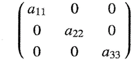
Other matrix types include a mixture of content element types (e.g., numeric or alphabetic characters), while still other matrix content element types include abstract mathematical forms (e.g., subscripts and superscripts). For example, fig. 11A shows a handwriting matrix having both numeric content elements ("0") and alphanumeric content elements with the alphanumeric content elements having alphabetic characters designated with subscript numbers. Similar to the indicator examples of fig. 8-10 described above, the formation of, for example, "a" is made by considering what is identified, e.g., the HWR system 114 identifies the subscript that is connected to the number and that is immediately to the left-hand side of the number 11 ”、“a 22 "and" a 33 ", since the subscripts are considered part of the larger content elements, and not the entire content elements themselves, the application 112 provides an identification matrix for the display of typeset ink as shown in FIG. 11B.
FIG. 12 shows a similar example input matrix with content elements including subscripts. However, unlike the previous example, the matrix of fig. 2 also includes empty content element locations or cells. That is, each row-column location is considered a cell, such that, for example, content element locations located at a first row (e.g., such as identified as row 0) and a first column (e.g., such as identified as column 0) correspond to " cell 0, 0". However, other forms of identifying the matrix element locations are possible. Further, the application 112 and/or HWR system 114 may apply such identifiers to the identified content as location data (e.g., a data tag) stored in, for example, the memory 108 of the device 100. The presence of such empty cells may present another challenge to correctly identify the content of a two-dimensional structure (e.g., a matrix), since it is envisaged that the identification of the rows and columns of the structure can only be determined by considering elements from other rows and/or columns, rather than elements in the same row and/or column of the considered elements. For example, elements in an otherwise empty row (or column) are not aligned with any other elements, and thus a row (or column) is identified by considering non-aligned elements. Even in such content scenarios, the present systems and methods provide robust matrix detection, as described in detail below.
As previously mentioned, the presence of fence elements can be used to help identify the matrix, particularly when empty cells are present. This is because, if the presence of a fence element is interpreted to mean that content surrounded by, contained by, or otherwise adjacent to the fence element (e.g., in a single fence scene) is laid out in one or more rows and one or more columns, then the empty cells are considered to be part of those rows and/or columns rather than non-content. However, as previously described, the present systems and methods are capable of identifying two-dimensional content structures without the presence or assistance of structure indicators (e.g., fence elements of a matrix). For example, fig. 13 shows an example input matrix with empty cells as in the example of fig. 12, but differs from fig. 12 in that there are no fence elements. The present system and method still correctly identifies the row and column structure of fig. 13, however, the identification result may or may not be identified as a matrix. That is, it may happen to be recognized as a two-dimensional structure, but it may not have any practical consequences depending on any subsequent use of the recognition result. Even in this case, for example, the user's selection may be provided via a UI or the like, and/or by feedback or preview of the recognition result (e.g., displaying generated numbers or typeset ink fence elements surrounding the displayed content elements) so that the recognized result is specified as a matrix. Such features of the present systems and methods are described in detail later.
More complex two-dimensional structures are also possible. FIG. 14A illustrates the example 2 × 3 digital ink matrix of FIG. 5A with additional inputs. In particular, a 3 × 2 handwriting matrix is input immediately to the right of the 2 × 3 matrix, followed by an equal sign "═ and another matrix comprising two mathematical equations. It can be seen that the rightmost matrix comprises the partial result of the multiplication of the first two matrices, i.e. the product of the 0 th row of the 2 x 3 matrix and the 0 th column of the 3 x 2 matrix, and the product of the 1 st row of the 2 x 3 matrix and the 1 st column of the 3 x 2 matrix, wherein the complete result will form the intended 2 x 2 matrix. Fig. 14B shows the recognition output of the typeset form, and it can be seen that the equations of the third matrix are correctly recognized as belonging to the cell 0, 0 and the cell 1, 1 of the 2 × 2 matrix. Recognition results were obtained despite the relatively significant overlap of the handwritten equations, as shown in fig. 14A. As previously described, this identification is accomplished by the present system and method by considering the identification of the equations within the rows of the third matrix, and may also be identified by considering the contents of the entire identification (e.g., the desired 2 x 2 matrix resulting from the product of the 2 x 3 matrix and the 3 x 2 matrix). These features are described in more detail later.
By treating the content elements as belonging to a two-dimensional structure of units for one or more identified elements of each content element based on the recognition results of the HWR system 114, rather than processing the individual input elements individually to determine the unit assignments, the present systems and methods are able to detect even more complex matrix forms with substantial accuracy. For example, FIG. 15 shows an example handwritten 2 x 2 matrix in which each content element includes a relatively complex mathematical function that combines many of the aforementioned content features (e.g., alphabetic characters, words, numbers, superscripts, parentheses, symbols, and indicators (e.g., minus sign and divide-by-normal)). However, despite this complexity, the present system and method detects a 2 x 2 matrix because the identified complex portion of each identified function is treated as belonging to a single content element of the corresponding matrix cell. Further, fig. 16 shows an example handwritten 3 x 3 matrix including nested matrices, e.g., cell 0, 0 includes a 2 x 2 sub-matrix, cell 1, 1 includes a 2 x 3 sub-matrix, and cell 2, 2 includes a 2 x 3 sub-matrix.
While relatively complex matrices present challenges for detection and identification, excessively simple matrices (e.g., single row or column matrices) present challenges as well. Fig. 17 shows an example 1 × 3 handwriting matrix, and fig. 18 shows an example 3 × 1 handwriting matrix. In either case (similar to the problem of empty cells discussed above), there is no inter-row relationship for a 1 x 3 matrix, or no inter-column relationship for a 3 x 1 matrix, and it may be difficult to determine that there are multiple columns (or rows). This is because, in order to determine a row and a column, only the content elements within the row or column itself are sufficient, and therefore the value of the distance or spacing between those elements which is relevant to the set threshold or the like for the column or row determination is crucial to this determination. Basically, the less information available, the more problematic the determination becomes.
For example, in fig. 17, according to the threshold value set for column determination, the content may be identified as a 1 × 3 matrix having content elements "3", "7", and "2", or a 1 × 2 matrix having content elements "3" and "72", or not a matrix at all but content "372". Also, in fig. 18, according to the threshold value set for row determination, the content may be identified as a 3 × 1 matrix having content elements "4", "1", and "8", or a 2 × 1 matrix having content elements "4" and "18", or not a matrix at all but content "418" (vertically set). As previously mentioned, the secondary characteristics of the fence elements can aid in matrix detection itself, so that no non-matrix results occur, but this does not inform the application 112 of the internal structure of the matrix. Other characteristics (or tertiary characteristics) with respect to certain content types may be considered in the present systems and methods to assist in making this determination. For example, a required interval between input elements (e.g., numbers) for column recognition may be set to be smaller than an interval between input elements for other input elements (e.g., alphabetical characters). This is because, for numbers, when specifying a majority digit number, it is believed that they should be reasonably written close together. Such criteria may also facilitate more complex matrix detection, as in the example of fig. 7. Alternative or additional characteristics are also contemplated to properly detect such simple matrices as well as more complex matrices, as will be discussed in detail later.
In addition, as previously mentioned, the present systems and methods may also identify other forms of two-dimensional structures. For example, fig. 19 shows a mathematical function involving a determinant of a matrix, which like the matrix has rows and columns of elemental units. Fig. 20 shows such a determinant nested within a matrix. Furthermore, as can be seen (as with some of the foregoing examples), there may also be additional elements (e.g., mathematical operators and functions) that are external to the two-dimensional structure. For example, although these additional elements are identified as separate from the contents of the matrix, they may be used as context by the application 112 and/or the HWR system 114 to guide the identification of the matrix contents and matrix structure, as described above.
As can be seen from the foregoing examples, the range of natural variations of hand-drawn matrices is wide, and therefore a system that robustly determines the structural relationships of such matrices must be able to perform overall detection and identification over this wide range of variations. Of course, for example, certain restrictions apply, such as what should be correctly identified as a matrix, in order to comply with the general definition. Thus, the present system and method uses criteria and recognition results to correctly detect the matrix structure, as described below. Note that, in general, handwriting recognition recognizes the elements themselves only in consideration of the geometric relationship of the recognized elements, regardless of the structure in which the elements are input. Thus, the present system and method uses other information to provide such recognition using a probability-based approach that considers geometric and language model features to provide a coarse filtering of row and column candidates. These coarsely filtered matrix unit candidates may then be fine filtered using the results of the recognition process to identify the actual matrix. In this manner, the present system and method efficiently uses recognition to detect matrices by preprocessing matrix element candidates. It should be understood that the present systems and methods are applicable to identifying other structural relationships of handwritten content in which the content is typically aligned (e.g., tables, lists, etc.) by rows (horizontal or non-horizontal, e.g., diagonal) and columns (vertical or non-vertical, e.g., diagonal), because the identification of structures does not depend on the particular input indicator of the structure, but rather on the relative geometry of the identified content itself. These and other features of the present system and method will now be discussed.
The following description of the examples shown in fig. 21 to 31 relates to matrix identification, however similar descriptions apply to the identification of other structures as described above. Furthermore, the following description relates to column detection within an input matrix, but it will be apparent that the same process can also be used to detect rows, and thus cells of the matrix. In either case, the processing typically involves: the alignment of elements in generally horizontal and vertical directions (or directions based on the writing direction) is detected, and the identification of elements belonging to those alignments is used to provide detection of possible rows or columns of the matrix and identification of the elements themselves. The processing of row detection is performed prior to column detection to provide matrix cell detection and thus overall detection of the matrix. In the following example, alignment is detected as part of detecting candidate matrix columns and rows, which are then analyzed based on the identified content to provide an identified matrix output. Alternatively, detection of vertical and/or horizontal alignment may be performed in a different manner than the matrix row and/or column assumptions, for example, by a process of detecting Multiple lines, such as the multiparty program described in U.S. patent publication No.2017/0011262 entitled "System for registering Multiple Object Input and Method and Product for the Same" filed in the name of the applicant and assignee, the entire contents of which are incorporated herein by reference.
FIG. 21 shows an example arrangement 2100 of multiple input ink objects 2102-2116. The ink objects represent handwritten input elements (e.g., one or more strokes forming one or more characters, symbols, etc.) input to, for example, an input surface 104 of the device 100 and are rendered as digital ink on the input surface 104. The ink object is shown generally as a rectangle that corresponds to the extent of the handwritten element, and thus may represent a bounding box of the element recognized by the HWR system 114. In this regard to the matrix detection process, the content of the ink object itself is not necessarily important, and the correspondence between the ink object used by the process and the identification element is important. Note that in the recognition process of the HWR system 114, the recognition result contains a hierarchical determination of recognition candidates for each stroke and group of strokes based on the language model employed. The ink objects shown relate to the most likely candidates for each recognition element, however, if the user selects a different candidate through, for example, a UI or the like, the content of the actual recognition and thus the recognized elements may change, such that the arrangement itself changes. In this case, the matrix detection process is at least partly used again to adapt the changed arrangement, e.g. to adapt at least for the part of the arrangement that is changed.
As can be seen, in arrangement 2100, ink objects 2102, 2104, and 2106 are generally horizontally aligned with one another, ink objects 2108 and 2110 are generally horizontally aligned with one another, and ink objects 2112, 2114, and 2116 are generally horizontally aligned with one another. As such, these horizontal alignments are detected by the present systems and methods in the manner previously described, and in the illustrated example, are likely to be determined to correspond to possible matrix rows, since there is no overlap between the aligned elements. Further, ink objects 2102, 2108, and 2112 are substantially vertically aligned with each other, ink objects 2104, 2110, and 2114 are substantially vertically aligned with each other, and ink objects 2106 and 2116 are substantially vertically aligned with each other. As such, these vertical alignments can be detected by the present systems and methods, and in the illustrated example, can be determined to correspond to possible matrix columns. Thus, for example, the arrangement 2100 may be detected as corresponding to a 3 × 3 matrix. Possible columns of such a matrix are detected as in the examples of fig. 22 to 31 below.
As shown in fig. 22, the known objects 2102, 2104, and 2106 are substantially horizontally aligned and, based on the recognition result of the HWR system 114, the known objects are (possibly) separate content elements. Thus, application 112 assigns objects 2102, 2104, and 2106, respectively, to a separate, possibly first column C 0 The second row C 1 And the third column C 2 In (1). These column assignment hypotheses are tested by considering whether any ink objects in the next horizontal alignment (in the downward direction, in this example) vertically overlap the ink objects of the columns. That is, by projecting the range of these objects into the next horizontal line, it is determined whether there are any ink objects and the width of each of the ink objects 2102, 2104, and 2106And (4) overlapping. This is essentially consistent with checking whether the ink objects 2108 and 2110 vertically overlap the ink objects 2102, 2104, and 2106. In FIG. 22, this is depicted by the dashed projection of the right-hand and left-hand demarcations of the bounding boxes of ink objects 2102, 2104, and 2106. As can be seen, it is determined that ink object 2108 overlaps ink object 2102, but that ink object 2110 does not overlap any of ink objects 2102, 2104, and 2106. Thus, in FIG. 23, it is shown that ink object 2108 is assigned to first column C having ink object 2102 0 Ink object 2104 is still assigned to second column C 1 Ink object 2110 is assigned to third column C 2 Is adjusted according to the assignment depicted in fig. 22, and the ink object 2106 is assigned to the fourth column C 3 In (1).
Next, these column-assigned hypotheses are again tested by considering whether any ink objects in the next horizontal alignment vertically overlap the ink objects of the columns. That is, it is determined whether any ink objects overlap the width of each of the ink objects 2108, 2104, 2110, and 2106 by projecting a range of these objects into the next horizontal line. This is essentially in line with checking whether ink objects 2112, 2114, and 2116 vertically overlap with ink objects 2102, 2104, and 2106. In FIG. 23, this is depicted by the dashed projection of the right-hand and left-hand demarcations of the bounding boxes of ink objects 2108, 2104, 2110, and 2106. As can be seen in FIG. 23, it is determined that ink object 2112 overlaps ink object 2108, that ink object 2114 overlaps both ink objects 2104 and 2110, and that ink object 2116 overlaps ink object 2106. Thus, in FIG. 24, ink object 2112 is shown assigned to the first column C having ink objects 2102 and 2108 0 Ink object 2114 is assigned to the second column C having ink object 2104 1 Ink object 2110 is also reassigned to second column C 1 And ink object 2116 is assigned to the third column C 2 In the third column C 2 With the ink objects 2106 being redistributed from the fourth column depicted in figure 23. The possible column identification results are depicted in FIG. 25, where three are shown in FIG. 25Column C 0 、C 1 And C 2 Are shown as dashed bounding boxes that enclose the ink objects assigned to the columns.
The column reassignment depicted in fig. 24 essentially represents a fine filtering of the column detection of the present system and method, wherein the detection of columns converges more closely and more closely spaced content elements are considered row by row. However, this filtering may not be performed at this stage, and all possible columns found in each step may be retained before subsequent filtering to check if any columns should be merged. This process is described in detail later.
When all possible hypotheses are determined and tested, the application 112 may provide (meta) data to the ink object, e.g., a tag indicating the row and column assignments (e.g., cell assignments) identified for the ink object, where such data is stored, e.g., with the ink object in the memory 108 of the device 100. In this manner, the positional relationship between the objects may be considered in any subsequent interaction (e.g., typesetting or editing) with the ink objects.
The above-described iterative method of assuming and testing column assignments row by row and by considering spatially adjacent content elements in those rows corresponds substantially to iteratively considering a 2 x 2 arrangement of objects in the overall arrangement in order to find possible columns. That is, the relative positions of two adjacent content elements in a first row are compared to two adjacent content elements in the next (second) row to determine (and adjust) the column assignment. This may be performed in a number of ways. In one example, the relative distance between features of content elements is compared to a threshold to determine whether the elements are likely to be grouped into different columns. That is, a suitable column spacing is searched between these elements.
For example, in the present case, the first column of tests is assumed to be ink object 2102 in the first column and the next ink object for the row (i.e., ink object 2104) in the second column, the second column of tests is assumed to be ink object 2102 in the first column and the leftmost ink object for the next row (i.e., ink object 2108) in the second column. This may be done, for example, by considering whether the horizontal distance between the right-hand boundary of the bounding box of ink object 2102 and the left-hand boundary of the bounding boxes of ink objects 2104 and 2108 is greater than a (first) threshold. In the simplest case, the first threshold is set to zero, or in some cases, to a non-zero (e.g., positive) value, so that any object that vertically overlaps the object under consideration returns a negative distance. That is, a measured distance such as the distance between objects 2102 and 2014 yields a positive value greater than the first threshold, and a measured distance such as the distance between ink objects 2102 and 2108 yields a negative value less than the first threshold. Thus, application 112 correctly determines that ink objects 2102 and 2104 may belong to different columns, and that ink objects 2102 and 2108 may not belong to different columns.
The intra-row comparison is essentially the horizontal row determination described above, and the inter-row comparison is essentially the projection of the higher left-most object onto the next successive horizontal row described above, where the projection forms approximately the fourth element of the 2 x 2 arrangement tested. It will be appreciated that an ink object may be defined by different characteristics than a bounding box (e.g., the extent of the stroke itself, the average center or centroid of the stroke making up each element, etc.). Further, distance may be measured in terms of pixels as a function of some other parameter of the input surface 104 (such as guidance for writing, e.g., an input line pattern described in U.S. patent publication No.2017/0060819 entitled "System and Method of digital Note tagging," filed in the name of the applicant and assignee hereof, claiming priority date of 8-25/2015, which is incorporated herein by reference in its entirety), etc.), as well as in terms of characteristics of the input itself (such as an arithmetic mean or average size of handwritten objects (e.g., characters), bounding boxes, etc., or combinations of such features, etc.). Further, it should be understood that the iterative approach may be based on a temporal order of the input of strokes/elements rather than the spatial order described above, or some combination thereof.
Therefore, an iterative 2 × 2 arrangement of objects is considered in the overall arrangement in order to find possible columns. In this way, local variations in the placement of handwritten elements are considered locally, so that they do not affect overall column detection in the overall placement. That is, applicants have found that users of digital applications for handwriting input of two-dimensional structures (e.g., matrices) tend to skew the spacing of structural elements as the size of the structure increases, particularly where, for example, the elements are conventional matrices of the same type. For example, for a simple 2 x 2 matrix, the relative spacing and size of the elements is reasonably consistent (e.g., as in fig. 4), however, as the matrix grows, some local compression or expansion of the element spacing may occur (e.g., as in fig. 8), where the spacing of the elements toward the upper right corner is expanded and the spacing of the elements at the lower center is slightly compressed and not horizontally aligned compared to the elements at the upper left corner of the matrix that is the starting position for writing.
The spatial sequential method described above is generally applicable to post-processing of inputs, i.e., processing for recognizing a matrix is performed by manual selection of a control element (e.g., a menu button), or input gestures (e.g., multiple touches on a surface, such as double-clicking), or by automatic processing (e.g., delayed by a set amount of time after input, e.g., about half a second to about two seconds) when a user has handwritten all of the intended inputs of the matrix. By using such triggers, this spatial approach is also applicable to processing during input, so-called incremental recognition. The time method is also applicable to incremental or post-recognition processing. Note that the incremental approach using spatial and/or temporal considerations may reduce the processing time for the final recognition of the input, for example, when the user indicates a desire to convert to a composition or after a time delay since the last input of the initial setting, since most of the processing is performed during the input.
From the foregoing example, it can be seen that by projecting the content elements of earlier rows to later rows to determine possible columns, the presence of empty cells does not affect the detection of columns, and in fact, empty cells are correctly assigned within a column, e.g., empty cells between ink objects 2106 and 2116 are assigned to a third column C 2 And (4) the following steps. However, also in the case of an input where there is only a single content element within a column (as is the case with the example matrix of fig. 12), this is the caseThis is the case. For example, fig. 26 shows an alternative example arrangement 2600 that is the same as arrangement 2100 but without ink objects 2114. Thus, through the identification process of the present system and method as described above, it can be determined that there are four columns C 0 、C 1 、C 2 And C 3 As indicated by the dashed bounding box that encloses the ink objects assigned to these columns. This is because, unlike the previous example of arrangement 2100, ink object 2114 does not overlap with both ink objects 2104 and 2110, so both ink objects 2104 and 2110 are still assigned to the second column and the third column, as determined at the stage of fig. 23 in the previous example. Thus, in this alternative example, each of objects 2104 and 2110 are assigned as the only object within their respective columns, and empty cells around those objects are also assigned into those columns.
Due to unaligned elements (due to non-uniformity of handwriting), unaligned elements (e.g., sign indicators, e.g., signs), and complex elements (e.g., submatrices, equations), the foregoing example "coarse" column detection processing may cause excessive vertical alignment to be detected, as variously depicted in the examples of fig. 4-20. Thus, as previously described, the present systems and methods may also process coarse detection results using a fine detection process, where it is determined whether some of the detected possible columns should be merged. Examples of such further processing are now described with reference to fig. 27-31.
As previously described, the first threshold may be set to a positive value. Such an arrangement essentially provides a certain amount of inner margin around each ink object, thereby increasing the required spacing between columns for detection. This inner-margin may be used in an initial "coarse" filtering or a subsequent "fine" filtering to provide a mechanism to merge closely spaced columns. For example, fig. 27 shows processing at a stage of the previous example of fig. 22, but with a certain amount of inner-edge distance p (designated by the circles in fig. 27) applied to ink objects 2102, 2104, and 2106 of alternative arrangement 2600 of fig. 26. In this example, the value of the first threshold is set such that inner edge p vertically overlaps ink object 2110 with ink object 2104. Thus, the column detection processing of the present system and method results in a column assignment as shown in FIG. 28, where objects 2104 and 2110 are again assigned to the same column in a three column layout, as in the example of arrangement 2100. The value of the first threshold may be arbitrarily set (and may be reset by the user, e.g., via the UI), or may be automatically defined by the present systems and methods, e.g., with reference to the nature of the handwriting (such as the arithmetic mean or average size of a handwritten object, such as a character).
An alternative or additional mechanism for fine-filtering column assignments is to consider the relative spacing of elements in the identified two-dimensional structure. This can be done in several ways. FIG. 29 shows an arrangement 2100 in which the horizontal distance between each ink object 2102-2116 is shown. That is, the distance d between objects 2102 and 2104 1 Distance d between objects 2108 and 2110 2 Distance d between objects 2112 and 2114 3 Distance d between objects 2104 and 2106 4 And the distance d between objects 2114 and 2116 5 . From these distances, the average, arithmetic mean, minimum and maximum distances between content elements of each column may be determined. For example, column C 0 And C 1 Average distance d between m1 Is a distance d 1 、d 2 And d 3 And column C, and 1 and C 2 Average distance d between m2 Is a distance d 4 And d 5 Average value in between. This normalized distance of the roughly assigned column may be compared to other parameters of the input arrangement, provided as a further (second) threshold for column detection, to provide a check of the assignment.
An example of such a parameter as a second threshold is the spacing between possible columns detected. For example, the spacing is shown differently in FIGS. 25, 26, and 28 as distance d g1 、d g2 And d g3 These distances d g1 、d g2 And d g3 Is in respect of column C 0 To C 3 The following symbol of each column in (1) " nL "and" nR "(where" n "is the number of columns (e.g., 0 to 3)) indicates the right hand score of the column bounding boxMeasured between the demarcation line and the left hand demarcation line. For example, the second threshold set for this parameter for a combined row may be a proportionally maximum positive interval (e.g., d in fig. 25) g2 ) The predetermined constant value (e.g., about 0.1 to about 0.7, and typically about 0.3) is scaled down to provide a natural variation of handwriting for the average distance from each column (e.g., average distance d) m1 And d m2 ) A comparison is made. Based on the comparison, if the average distance is less than the second threshold, the columns are merged. In this way, detection columns that are much less spaced than the most spaced columns (which are considered to have a higher likelihood of being columns) are merged because they are less likely to constitute a column.
Another example of such a parameter as a second threshold is an interval within certain content elements. For example, the spacing between content features such as alphabetic characters, words, numbers, superscripts, subscripts, parentheses, symbols, and indicators (e.g., minus and plus signs, and divide by normal). For example, FIG. 30 shows a separation distance d c1 The two elements 3000 and 3002. For example, element 3000 may be an indicator (e.g., a negative sign) and element 3002 may be a number. The present systems and methods may treat these adjacent elements as identified by the HWR system 114 as a single content element based on rules set in the application 112, or the HWR system 114 may itself return ink objects in a manner such as described previously with respect to fig. 8, 9, and 10. For example, the second threshold set for the parameter for merging columns may be to scale the maximum positive separation between the elements by a predetermined constant value (e.g., about 1.1 to about 1.7, and typically about 1.4) to provide a natural variation in handwriting and compare the value to the average distance per column. Based on the comparison, if the average distance is less than the second threshold, then the columns are merged, as shown in FIG. 31, where the first and second columns of FIG. 25 are merged because, for example, the distance d g1 Less than the scaled distance d c1 So that two reallocated columns C are reserved 0 And C 1 . In this manner, the spacing is much smaller compared to the largest spaced connected elements (e.g., numbers connected in negative and plus signs)The detected columns are merged because they may not constitute columns because the expected column spacing is wider than the inter-element spacing.
An average or other common value of the spacing of ink objects in each of the coarsely detected columns is used in the above-described merge operation based on the global and maximum features of the identified structure to provide a relatively robust assessment of any possible over-segmentation of the structure due to local variations within the structure.
As previously described, the above-described example of column detection may also be applied to row detection, where the vertical alignment is known from the HWR system 114 and used by the application 112 to determine rows. Furthermore, in the above examples of coarse and fine two-dimensional structure detection, the detection results may be provided as one or more probability scores for each detected column and row, which are calculated, for example, from the geometric cost of the probability result. That is, the first threshold and the second threshold described are parameters that are compared to the geometric relationship of the recognized content of the handwritten input to determine the geometric cost of the recognized content in a particular structure (e.g., rows and columns). This cost may be supplemented to the actual recognition results from the HWR system 114 and/or the structure detection results of the application 112 as a weighting of the probabilities generated, for example, by handwriting recognition results. In this manner, certain identified content may readily impact subsequent assignment of structural elements, such as allowing closer spacing, juxtaposition and/or rows of numbers, increasing the probability of the matrix based on similarity of content (e.g., all numbers, characters, equations), increasing the probability score of the matrix if bracket or fence elements are detected near content elements, as previously described.
The various examples described herein may be applied to forms of input other than handwriting for recognition (e.g., offline recognition where an image is recognized rather than digital ink), e.g., images captured as photographs written on paper or a whiteboard, images digitally captured on an interactive smart board, etc.
The described methods and systems increase the speed of processing and recognition of multiple objects in a two-dimensional structure (e.g., a matrix of numbers, characters, mathematical functions or equations, and combinations thereof) because structure recognition is performed in view of recognition of the objects themselves. Furthermore, the writing structure (e.g., matrix) does not require specific user actions for recognition, such as creating a new writing area, clicking a new matrix button, drawing parentheses, etc. Further, the algorithm need not be learned or trained, but can be performed to improve the results.
While the foregoing has described what are considered to be the best mode and/or other examples, it is understood that: various modifications may be made in the present invention, and the subject matter disclosed herein may be implemented in various forms and examples, and the contents of the best mode and/or other examples may be applied in numerous other applications, combinations and environments, only some of which are described herein. Those of ordinary skill in the art will recognize that the disclosed aspects may be altered or modified without departing from the true spirit and scope of the present subject matter. Therefore, the subject matter is not limited to the specific details, illustrations, and examples in this specification. It is intended herein to cover any and all modifications and variations that fall within the true scope of the advantageous concepts disclosed herein.
Claims (12)
1. A system for recognizing handwriting input comprising an arrangement of a plurality of ink objects, the ink objects representing handwriting elements in horizontal and vertical columns of a two-dimensional structure, the handwriting elements being input to a computing device, the computing device comprising a processor, a memory, and at least one non-transitory computer-readable medium for recognizing handwriting input under control of the processor and configured to:
identifying a plurality of handwritten elements having respective bounding boxes;
determining at least one geometric relationship between a plurality of recognized handwriting elements of the handwriting input; and
assigning the recognized handwritten elements having said at least one geometrical relationship between them to corresponding positions in the arrangement of recognized handwritten elements,
wherein:
the at least one geometric relationship is a projected overlap of a plurality of bounding boxes in one direction in the arrangement;
the overlap of the projections of the two bounding boxes of respective ink objects on different rows is determined by considering whether a directed horizontal distance between the projection of the bounding box of the first ink object and the projection of the bounding box of the second ink object is less than a threshold, wherein two ink objects are assigned to the same column if the directed horizontal distance is less than the threshold.
2. The system of claim 1, wherein the locations in the arrangement are cells in a two-dimensional structure of the identification elements.
3. The system of claim 1, wherein the at least one geometric threshold is based on at least one geometric spacing of at least some of the identified elements.
4. A system according to claim 3, wherein the at least one geometric separation is a maximum separation between components of at least some of the identifying elements.
5. A method for recognizing handwriting input comprising an arrangement of a plurality of ink objects representing handwriting elements in horizontal rows and vertical columns of a two-dimensional structure, the handwriting elements being input to a computing device, the method comprising:
identifying a plurality of handwritten elements having respective bounding boxes;
determining at least one geometric relationship between a plurality of recognized handwriting elements of the handwriting input; and
assigning the recognized handwritten elements having said at least one geometrical relationship between them to corresponding positions in the arrangement of recognized handwritten elements,
wherein:
the at least one geometric relationship is a projected overlap of a plurality of bounding boxes in one direction in the arrangement;
the overlap of the projections of the two bounding boxes of respective ink objects on different rows is determined by considering whether a directed horizontal distance between the projection of the bounding box of the first ink object and the projection of the bounding box of the second ink object is less than a threshold, wherein two ink objects are assigned to the same column if the directed horizontal distance is less than the threshold.
6. The method of claim 5, wherein the locations in the arrangement are cells in a two-dimensional structure of the identification elements.
7. The method of claim 5, wherein the at least one geometric threshold is based on at least one geometric spacing of at least some of the identifying elements.
8. The method of claim 7, wherein the at least one geometric separation is a maximum separation between components of at least some of the identification elements.
9. A non-transitory computer readable medium having embodied therein a computer readable program code adapted to be executed to implement a method for recognizing a handwriting input comprising an arrangement of a plurality of ink objects representing handwriting elements in horizontal rows and vertical columns of a two-dimensional structure, the handwriting elements being input to a computing device, the method comprising:
identifying a plurality of handwritten elements having respective bounding boxes;
determining at least one geometric relationship between a plurality of recognized handwriting elements of the handwriting input; and
assigning the recognized handwritten elements having the at least one geometric relationship between them to corresponding locations in the arrangement of recognized handwritten elements,
wherein:
the at least one geometric relationship is a projected overlap of a plurality of bounding boxes in one direction in the arrangement;
the overlap of the projections of the two bounding boxes of respective ink objects on different rows is determined by considering whether a directed horizontal distance between the projection of the bounding box of the first ink object and the projection of the bounding box of the second ink object is less than a threshold, wherein two ink objects are assigned to the same column if the directed horizontal distance is less than the threshold.
10. The non-transitory computer-readable medium of claim 9, wherein a location in the arrangement is a cell in a two-dimensional structure of the identification elements.
11. The non-transitory computer-readable medium of claim 9, wherein the at least one geometric threshold is based on at least one geometric spacing of at least some of the identifying elements.
12. The non-transitory computer-readable medium of claim 11, wherein the at least one geometric separation is a maximum separation between components of at least some of the identification elements.
Applications Claiming Priority (5)
| Application Number | Priority Date | Filing Date | Title |
|---|---|---|---|
| EP16290015 | 2016-01-20 | ||
| EP16290015.3 | 2016-01-20 | ||
| US15/152,762 US10013603B2 (en) | 2016-01-20 | 2016-05-12 | System and method for recognizing multiple object structure |
| US15/152,762 | 2016-05-12 | ||
| PCT/EP2017/000074 WO2017125248A1 (en) | 2016-01-20 | 2017-01-20 | System and method for recognizing multiple object structure |
Publications (2)
| Publication Number | Publication Date |
|---|---|
| CN108701215A CN108701215A (en) | 2018-10-23 |
| CN108701215B true CN108701215B (en) | 2022-08-02 |
Family
ID=55436052
Family Applications (1)
| Application Number | Title | Priority Date | Filing Date |
|---|---|---|---|
| CN201780007367.8A Active CN108701215B (en) | 2016-01-20 | 2017-01-20 | System and method for identifying multi-object structures |
Country Status (6)
| Country | Link |
|---|---|
| US (1) | US10013603B2 (en) |
| EP (1) | EP3405906A1 (en) |
| JP (1) | JP6877446B2 (en) |
| KR (1) | KR102463657B1 (en) |
| CN (1) | CN108701215B (en) |
| WO (1) | WO2017125248A1 (en) |
Families Citing this family (6)
| Publication number | Priority date | Publication date | Assignee | Title |
|---|---|---|---|---|
| US10620824B2 (en) | 2016-09-30 | 2020-04-14 | Atlassian Pty Ltd | Creating tables using gestures |
| US11032336B2 (en) | 2018-03-23 | 2021-06-08 | Motorola Solutions, Inc. | Methods and systems for providing supplementary information on a virtual whiteboard |
| US10826572B2 (en) * | 2018-04-16 | 2020-11-03 | Microsoft Technology Licensing, Llc | Preserving digital ink spatial relationships in electronic messages |
| US10748031B1 (en) | 2019-05-22 | 2020-08-18 | Read-Ink Corporation | Handwriting recognition systems and methods |
| CN110363149B (en) * | 2019-07-16 | 2021-12-03 | 广州视源电子科技股份有限公司 | Handwriting processing method and device |
| CN114491368B (en) * | 2022-01-20 | 2024-03-08 | 抖音视界有限公司 | Form locator generating method, form operation method, device, medium and equipment |
Citations (7)
| Publication number | Priority date | Publication date | Assignee | Title |
|---|---|---|---|---|
| CN1625766A (en) * | 2001-04-09 | 2005-06-08 | I.C.+技术有限公司 | Apparatus and method for hand motion tracking and handwriting recognition |
| CN1652139A (en) * | 1999-05-25 | 2005-08-10 | 西尔弗布鲁克研究股份有限公司 | System and method for forming interactive books |
| CN1719454A (en) * | 2005-07-15 | 2006-01-11 | 清华大学 | Off-line hand writing Chinese character segmentation method with compromised geomotric cast and sematic discrimination cost |
| CN101930545A (en) * | 2009-06-24 | 2010-12-29 | 夏普株式会社 | Handwriting recognition method and device |
| TW201201113A (en) * | 2010-06-22 | 2012-01-01 | Sharp Kk | Handwriting recognition method and device |
| CN105117054A (en) * | 2015-08-12 | 2015-12-02 | 珠海优特电力科技股份有限公司 | Handwriting input recognition method and system |
| CN105247540A (en) * | 2013-06-09 | 2016-01-13 | 苹果公司 | Managing real-time handwriting recognition |
Family Cites Families (20)
| Publication number | Priority date | Publication date | Assignee | Title |
|---|---|---|---|---|
| JPS60136892A (en) * | 1983-12-26 | 1985-07-20 | Hitachi Ltd | On-line recognition device of hand written graphic |
| DE19581757T1 (en) * | 1994-09-09 | 1997-08-21 | Motorola Inc | Method and system for recognizing a boundary between characters in handwritten text |
| US5970170A (en) * | 1995-06-07 | 1999-10-19 | Kodak Limited | Character recognition system indentification of scanned and real time handwritten characters |
| US6094506A (en) * | 1995-10-25 | 2000-07-25 | Microsoft Corporation | Automatic generation of probability tables for handwriting recognition systems |
| US20030215145A1 (en) * | 2002-05-14 | 2003-11-20 | Microsoft Corporation | Classification analysis of freeform digital ink input |
| US7447360B2 (en) | 2004-09-22 | 2008-11-04 | Microsoft Corporation | Analyzing tabular structures in expression recognition |
| US7561737B2 (en) * | 2004-09-22 | 2009-07-14 | Microsoft Corporation | Mathematical expression recognition |
| US7593574B2 (en) * | 2005-07-01 | 2009-09-22 | Microsoft Corporation | Ink warping for normalization and beautification / ink beautification |
| US8045803B2 (en) * | 2007-11-09 | 2011-10-25 | Jeffrey Scott Nelson | Handwriting recognition system and methodology for use with a latin derived alphabet universal computer script |
| US8121412B2 (en) * | 2008-06-06 | 2012-02-21 | Microsoft Corporation | Recognition of tabular structures |
| US20100246941A1 (en) * | 2009-03-24 | 2010-09-30 | Microsoft Corporation | Precision constrained gaussian model for handwriting recognition |
| US8175389B2 (en) * | 2009-03-30 | 2012-05-08 | Synaptics Incorporated | Recognizing handwritten words |
| US8768062B2 (en) * | 2010-11-09 | 2014-07-01 | Tata Consulting Services Limited | Online script independent recognition of handwritten sub-word units and words |
| CN102156865A (en) * | 2010-12-14 | 2011-08-17 | 上海合合信息科技发展有限公司 | Handwritten text line character segmentation method and identification method |
| CN102156577B (en) * | 2011-03-28 | 2013-05-29 | 安徽科大讯飞信息科技股份有限公司 | Method and system for realizing continuous handwriting recognition input |
| CN103366151B (en) * | 2012-03-30 | 2017-05-31 | 佳能株式会社 | Hand-written character recognition method and equipment |
| US10176291B2 (en) * | 2012-07-06 | 2019-01-08 | Siemens Product Lifecycle Management Software Inc. | Ordering optional constraints in a variational system |
| CN103093196B (en) * | 2013-01-14 | 2014-08-27 | 大连理工大学 | Character interactive input and recognition method based on gestures |
| JP6451316B2 (en) * | 2014-12-26 | 2019-01-16 | 富士通株式会社 | Character recognition program, character recognition method, and character recognition device |
| US10643067B2 (en) * | 2015-10-19 | 2020-05-05 | Myscript | System and method of handwriting recognition in diagrams |
-
2016
- 2016-05-12 US US15/152,762 patent/US10013603B2/en active Active
-
2017
- 2017-01-20 EP EP17703316.4A patent/EP3405906A1/en active Pending
- 2017-01-20 JP JP2018538170A patent/JP6877446B2/en active Active
- 2017-01-20 WO PCT/EP2017/000074 patent/WO2017125248A1/en active Application Filing
- 2017-01-20 KR KR1020187023832A patent/KR102463657B1/en active IP Right Grant
- 2017-01-20 CN CN201780007367.8A patent/CN108701215B/en active Active
Patent Citations (7)
| Publication number | Priority date | Publication date | Assignee | Title |
|---|---|---|---|---|
| CN1652139A (en) * | 1999-05-25 | 2005-08-10 | 西尔弗布鲁克研究股份有限公司 | System and method for forming interactive books |
| CN1625766A (en) * | 2001-04-09 | 2005-06-08 | I.C.+技术有限公司 | Apparatus and method for hand motion tracking and handwriting recognition |
| CN1719454A (en) * | 2005-07-15 | 2006-01-11 | 清华大学 | Off-line hand writing Chinese character segmentation method with compromised geomotric cast and sematic discrimination cost |
| CN101930545A (en) * | 2009-06-24 | 2010-12-29 | 夏普株式会社 | Handwriting recognition method and device |
| TW201201113A (en) * | 2010-06-22 | 2012-01-01 | Sharp Kk | Handwriting recognition method and device |
| CN105247540A (en) * | 2013-06-09 | 2016-01-13 | 苹果公司 | Managing real-time handwriting recognition |
| CN105117054A (en) * | 2015-08-12 | 2015-12-02 | 珠海优特电力科技股份有限公司 | Handwriting input recognition method and system |
Non-Patent Citations (6)
| Title |
|---|
| An On-line Handwritten Mathematical Equation Recognition System that Can Process Matrix Expressions by Referring to the Relative Positions of Matrix Elements;Kenichi Toyozumi等;《Systems and Computers in Japan》;20061231;第37卷(第14期);第87-96页 * |
| ICFHR 2014 Competition on Recognition of On-line Handwritten Mathematical Expressions (CROHME 2014);H. Mouchère等;《2014 14th International Conference on Frontiers in Handwriting Recognition》;20141215;第1-6页 * |
| Online Recognition of Handwritten Mathematical Expressions with Support for Matrices;Chuanjun Li等;《2008 19th International Conference on Pattern Recognition》;20090123;第1-4页摘要、第3、4节 * |
| TABLE RECOGNITION IN MATHEMATICAL DOCUMENTS;MOHAMED A. ALKALAI;《PhD Thesis》;20150101;第1-203页 * |
| 手写体数字识别中的关键技术研究;王岩松;《中国优秀硕士学位论文全文数据库 信息科技辑》;20100315(第(2010)03期);I138-709 * |
| 手写体笔迹识别中分类器的设计及实现;李奇等;《长春理工大学学报》;20051231;第28卷(第4期);第93-95页 * |
Also Published As
| Publication number | Publication date |
|---|---|
| EP3405906A1 (en) | 2018-11-28 |
| JP2019506672A (en) | 2019-03-07 |
| US20170206406A1 (en) | 2017-07-20 |
| WO2017125248A1 (en) | 2017-07-27 |
| KR102463657B1 (en) | 2022-11-10 |
| JP6877446B2 (en) | 2021-05-26 |
| KR20180104678A (en) | 2018-09-21 |
| US10013603B2 (en) | 2018-07-03 |
| CN108701215A (en) | 2018-10-23 |
Similar Documents
| Publication | Publication Date | Title |
|---|---|---|
| CN108701215B (en) | System and method for identifying multi-object structures | |
| US10664695B2 (en) | System and method for managing digital ink typesetting | |
| CN108027876B (en) | System for recognizing multiple object inputs, method and product thereof | |
| JP7105695B2 (en) | Systems and methods for digital ink interactivity | |
| US9384403B2 (en) | System and method for superimposed handwriting recognition technology | |
| CN108475325B (en) | System, method, and computer-readable medium for identifying handwritten pattern connectors | |
| CN108369637B (en) | System and method for beautifying digital ink | |
| US10579868B2 (en) | System and method for recognition of objects from ink elements | |
| CN114365075B (en) | Method for selecting a graphical object and corresponding device | |
| US11687618B2 (en) | System and method for processing text handwriting in a free handwriting mode | |
| EP3491580B1 (en) | System and method for beautifying superimposed digital ink | |
| US11429259B2 (en) | System and method for selecting and editing handwriting input elements | |
| CN114341954B (en) | Text line extraction | |
| US20230096728A1 (en) | System and method for text line and text block extraction | |
| US10884610B2 (en) | System and method for recognizing handwritten stroke input | |
| US20240134507A1 (en) | Modifying digital content including typed and handwritten text | |
| WO2022180016A1 (en) | Modifying digital content including typed and handwritten text |
Legal Events
| Date | Code | Title | Description |
|---|---|---|---|
| PB01 | Publication | ||
| PB01 | Publication | ||
| SE01 | Entry into force of request for substantive examination | ||
| SE01 | Entry into force of request for substantive examination | ||
| GR01 | Patent grant | ||
| GR01 | Patent grant |