CN108700298B - Combustion apparatus and gas turbine - Google Patents
Combustion apparatus and gas turbine Download PDFInfo
- Publication number
- CN108700298B CN108700298B CN201780014987.4A CN201780014987A CN108700298B CN 108700298 B CN108700298 B CN 108700298B CN 201780014987 A CN201780014987 A CN 201780014987A CN 108700298 B CN108700298 B CN 108700298B
- Authority
- CN
- China
- Prior art keywords
- fuel
- flow path
- injection holes
- nozzle
- injection hole
- Prior art date
- Legal status (The legal status is an assumption and is not a legal conclusion. Google has not performed a legal analysis and makes no representation as to the accuracy of the status listed.)
- Active
Links
Images


Classifications
-
- F—MECHANICAL ENGINEERING; LIGHTING; HEATING; WEAPONS; BLASTING
- F02—COMBUSTION ENGINES; HOT-GAS OR COMBUSTION-PRODUCT ENGINE PLANTS
- F02C—GAS-TURBINE PLANTS; AIR INTAKES FOR JET-PROPULSION PLANTS; CONTROLLING FUEL SUPPLY IN AIR-BREATHING JET-PROPULSION PLANTS
- F02C9/00—Controlling gas-turbine plants; Controlling fuel supply in air- breathing jet-propulsion plants
- F02C9/26—Control of fuel supply
- F02C9/40—Control of fuel supply specially adapted to the use of a special fuel or a plurality of fuels
-
- F—MECHANICAL ENGINEERING; LIGHTING; HEATING; WEAPONS; BLASTING
- F02—COMBUSTION ENGINES; HOT-GAS OR COMBUSTION-PRODUCT ENGINE PLANTS
- F02C—GAS-TURBINE PLANTS; AIR INTAKES FOR JET-PROPULSION PLANTS; CONTROLLING FUEL SUPPLY IN AIR-BREATHING JET-PROPULSION PLANTS
- F02C7/00—Features, components parts, details or accessories, not provided for in, or of interest apart form groups F02C1/00 - F02C6/00; Air intakes for jet-propulsion plants
- F02C7/22—Fuel supply systems
- F02C7/224—Heating fuel before feeding to the burner
-
- F—MECHANICAL ENGINEERING; LIGHTING; HEATING; WEAPONS; BLASTING
- F02—COMBUSTION ENGINES; HOT-GAS OR COMBUSTION-PRODUCT ENGINE PLANTS
- F02C—GAS-TURBINE PLANTS; AIR INTAKES FOR JET-PROPULSION PLANTS; CONTROLLING FUEL SUPPLY IN AIR-BREATHING JET-PROPULSION PLANTS
- F02C7/00—Features, components parts, details or accessories, not provided for in, or of interest apart form groups F02C1/00 - F02C6/00; Air intakes for jet-propulsion plants
- F02C7/22—Fuel supply systems
- F02C7/232—Fuel valves; Draining valves or systems
-
- F—MECHANICAL ENGINEERING; LIGHTING; HEATING; WEAPONS; BLASTING
- F02—COMBUSTION ENGINES; HOT-GAS OR COMBUSTION-PRODUCT ENGINE PLANTS
- F02C—GAS-TURBINE PLANTS; AIR INTAKES FOR JET-PROPULSION PLANTS; CONTROLLING FUEL SUPPLY IN AIR-BREATHING JET-PROPULSION PLANTS
- F02C9/00—Controlling gas-turbine plants; Controlling fuel supply in air- breathing jet-propulsion plants
- F02C9/26—Control of fuel supply
- F02C9/32—Control of fuel supply characterised by throttling of fuel
-
- F—MECHANICAL ENGINEERING; LIGHTING; HEATING; WEAPONS; BLASTING
- F23—COMBUSTION APPARATUS; COMBUSTION PROCESSES
- F23R—GENERATING COMBUSTION PRODUCTS OF HIGH PRESSURE OR HIGH VELOCITY, e.g. GAS-TURBINE COMBUSTION CHAMBERS
- F23R3/00—Continuous combustion chambers using liquid or gaseous fuel
- F23R3/02—Continuous combustion chambers using liquid or gaseous fuel characterised by the air-flow or gas-flow configuration
- F23R3/04—Air inlet arrangements
- F23R3/10—Air inlet arrangements for primary air
- F23R3/12—Air inlet arrangements for primary air inducing a vortex
- F23R3/14—Air inlet arrangements for primary air inducing a vortex by using swirl vanes
-
- F—MECHANICAL ENGINEERING; LIGHTING; HEATING; WEAPONS; BLASTING
- F23—COMBUSTION APPARATUS; COMBUSTION PROCESSES
- F23R—GENERATING COMBUSTION PRODUCTS OF HIGH PRESSURE OR HIGH VELOCITY, e.g. GAS-TURBINE COMBUSTION CHAMBERS
- F23R3/00—Continuous combustion chambers using liquid or gaseous fuel
- F23R3/28—Continuous combustion chambers using liquid or gaseous fuel characterised by the fuel supply
- F23R3/286—Continuous combustion chambers using liquid or gaseous fuel characterised by the fuel supply having fuel-air premixing devices
-
- F—MECHANICAL ENGINEERING; LIGHTING; HEATING; WEAPONS; BLASTING
- F23—COMBUSTION APPARATUS; COMBUSTION PROCESSES
- F23R—GENERATING COMBUSTION PRODUCTS OF HIGH PRESSURE OR HIGH VELOCITY, e.g. GAS-TURBINE COMBUSTION CHAMBERS
- F23R3/00—Continuous combustion chambers using liquid or gaseous fuel
- F23R3/28—Continuous combustion chambers using liquid or gaseous fuel characterised by the fuel supply
- F23R3/30—Continuous combustion chambers using liquid or gaseous fuel characterised by the fuel supply comprising fuel prevapourising devices
-
- F—MECHANICAL ENGINEERING; LIGHTING; HEATING; WEAPONS; BLASTING
- F23—COMBUSTION APPARATUS; COMBUSTION PROCESSES
- F23R—GENERATING COMBUSTION PRODUCTS OF HIGH PRESSURE OR HIGH VELOCITY, e.g. GAS-TURBINE COMBUSTION CHAMBERS
- F23R3/00—Continuous combustion chambers using liquid or gaseous fuel
- F23R3/28—Continuous combustion chambers using liquid or gaseous fuel characterised by the fuel supply
- F23R3/34—Feeding into different combustion zones
- F23R3/343—Pilot flames, i.e. fuel nozzles or injectors using only a very small proportion of the total fuel to insure continuous combustion
-
- F—MECHANICAL ENGINEERING; LIGHTING; HEATING; WEAPONS; BLASTING
- F23—COMBUSTION APPARATUS; COMBUSTION PROCESSES
- F23R—GENERATING COMBUSTION PRODUCTS OF HIGH PRESSURE OR HIGH VELOCITY, e.g. GAS-TURBINE COMBUSTION CHAMBERS
- F23R3/00—Continuous combustion chambers using liquid or gaseous fuel
- F23R3/28—Continuous combustion chambers using liquid or gaseous fuel characterised by the fuel supply
- F23R3/36—Supply of different fuels
-
- F—MECHANICAL ENGINEERING; LIGHTING; HEATING; WEAPONS; BLASTING
- F05—INDEXING SCHEMES RELATING TO ENGINES OR PUMPS IN VARIOUS SUBCLASSES OF CLASSES F01-F04
- F05D—INDEXING SCHEME FOR ASPECTS RELATING TO NON-POSITIVE-DISPLACEMENT MACHINES OR ENGINES, GAS-TURBINES OR JET-PROPULSION PLANTS
- F05D2240/00—Components
- F05D2240/35—Combustors or associated equipment
-
- F—MECHANICAL ENGINEERING; LIGHTING; HEATING; WEAPONS; BLASTING
- F05—INDEXING SCHEMES RELATING TO ENGINES OR PUMPS IN VARIOUS SUBCLASSES OF CLASSES F01-F04
- F05D—INDEXING SCHEME FOR ASPECTS RELATING TO NON-POSITIVE-DISPLACEMENT MACHINES OR ENGINES, GAS-TURBINES OR JET-PROPULSION PLANTS
- F05D2270/00—Control
- F05D2270/01—Purpose of the control system
- F05D2270/20—Purpose of the control system to optimize the performance of a machine
Landscapes
- Engineering & Computer Science (AREA)
- Chemical & Material Sciences (AREA)
- Combustion & Propulsion (AREA)
- Mechanical Engineering (AREA)
- General Engineering & Computer Science (AREA)
- Nozzles For Spraying Of Liquid Fuel (AREA)
Abstract
The combustion device is provided with: a nozzle housing defining an axial flow path; and a nozzle disposed within the axial flow path, the nozzle comprising: a cylindrical nozzle body extending along the axial flow path; a swirler vane configured to protrude radially outward from the nozzle body in a radial direction of the nozzle body and swirl a fluid flowing through the axial flow passage; at least one first injection hole opening at a surface of the nozzle body or the swirler vane; at least one second injection hole opening at a surface of the nozzle body or the swirler vane; a first fuel flow path extending inside the nozzle body and communicating with the at least one first injection hole; and a second fuel flow path extending inside the nozzle body independently of the first fuel flow path and communicating with the at least one second injection hole.
Description
Technical Field
The present disclosure relates to a combustion apparatus and a gas turbine.
Background
In a combustion apparatus used for a gas turbine or the like, there are cases where fuels having different properties are combusted depending on an operation state or the like.
For example, patent document 1 discloses a gas turbine combustor including a main fuel nozzle for ejecting fuel into a combustion chamber, a sub fuel nozzle for ejecting fuel into air before introduction into the combustion chamber, and a flow rate adjustment mechanism for adjusting a flow rate of fuel supplied to the main fuel nozzle and the sub fuel nozzle. In this gas turbine combustor, an appropriate amount of fuel corresponding to the properties of the fuel is supplied to the combustion chamber in order to stably combust the fuel. That is, the flow rates of the fuel supplied to the main fuel nozzle and the sub fuel nozzle are adjusted according to the properties (for example, the calorific value) of the fuel supplied to the main fuel nozzle and the sub fuel nozzle.
Prior art documents
Patent document
Patent document 1: japanese patent laid-open No. 2007-46843
Disclosure of Invention
Problems to be solved by the invention
However, when a predetermined combustion heat is to be obtained in a certain combustion apparatus, there are a case where a fuel having a relatively large inactive component content and a relatively small calorific value (hereinafter referred to as a low calorie fuel) is used and a case where a fuel having a relatively small inactive component content and a relatively large calorific value (hereinafter referred to as a high calorie fuel) is used.
When a low-calorie fuel is used, the flow rate ratio of the fuel needs to be made large in order to obtain a supply amount (flow rate) necessary for obtaining a predetermined combustion heat. Therefore, when using low-calorie fuel, the piping diameter, the nozzle diameter, and the like need to be relatively large in order to reduce the pressure loss in the piping and the like.
On the other hand, when using high-calorie fuel, the fuel supply amount (flow rate) required to obtain combustion heat equivalent to that when using low-calorie fuel is smaller than that when using low-calorie fuel, and therefore the flow rate ratio of fuel needs to be made small. Therefore, when the high-calorie fuel is applied to a pipe or a nozzle having a diameter suitable for the low-calorie fuel, the flow velocity of the fuel is reduced as compared with the case of using the low-calorie fuel, and therefore, the differential pressure between the front and rear of the nozzle injecting the fuel is reduced, and therefore, combustion vibration may occur in the combustor (combustion apparatus).
In view of the above, an object of at least one embodiment of the present invention is to provide a combustion apparatus that can easily maintain a differential pressure between before and after fuel injection even when fuels having different properties are applied.
Means for solving the problems
(1) A combustion apparatus according to at least one embodiment of the present invention includes:
a nozzle housing defining an axial flow path; and
at least one nozzle disposed within the axial flow path,
the at least one nozzle includes:
a cylindrical nozzle body extending along the axial flow path;
a swirler vane configured to protrude radially outward from the nozzle body in a radial direction of the nozzle body and swirl a fluid flowing through the axial flow passage;
at least one first injection hole opening at a surface of the nozzle body or the swirler vane;
at least one second injection hole opening at a surface of the nozzle body or the swirler vane;
a first fuel flow path extending inside the nozzle body and communicating with the at least one first injection hole; and
a second fuel flow path extending inside the nozzle body independently of the first fuel flow path and communicating with the at least one second injection hole.
In the configuration of the above (1), since the first fuel flow path and the second fuel flow path which communicate with the first injection hole and the second injection hole for injecting the fuel are provided, respectively, the design of the first fuel flow path and the first injection hole can be adapted to the property of the fuel flowing through the first fuel flow path, and the design of the second fuel flow path and the second injection hole can be adapted to the property of the fuel flowing through the second fuel flow path.
(2) In some embodiments, based on the structure of (1) above, a total area of the first injection holes is larger than a total area of the second injection holes.
In the configuration of the above (2), since the total area (for example, the sum of the opening areas or the sum of the flow passage areas) of the first injection holes is larger than the total area of the second injection holes, the flow rate of the fuel injected from the first injection holes is larger than that of the second injection holes. Therefore, when the fuel is injected from the first injection hole, the differential pressure before and after the first injection hole is easily maintained. On the other hand, since the total area of the second injection holes is smaller than the total area of the first injection holes, the differential pressure between the front and rear of the second injection holes is easily maintained although the flow rate of the fuel injected from the second injection holes is relatively small. Thus, according to the configuration of (2), the differential pressure between before and after the fuel injection can be easily maintained in the combustion apparatus.
(3) In some embodiments, based on the configuration of (2), a flow passage area of the first fuel flow passage is larger than a flow passage area of the second fuel flow passage.
In the configuration of the above (3), since the flow passage area of the first fuel flow passage is larger than the flow passage area of the second fuel flow passage, the flow rate of the fuel injected from the first injection hole is relatively large compared to the second injection hole. Therefore, when the fuel is injected from the first injection hole, the differential pressure is easily maintained before and after the first injection hole. On the other hand, since the flow passage area of the second fuel flow passage is smaller than the flow passage area of the first fuel flow passage, the differential pressure between the front and rear of the second injection hole is easily maintained although the flow rate of the fuel injected from the second injection hole is relatively small. Thus, according to the configuration of (3), the differential pressure between before and after the fuel injection can be easily maintained in the combustion apparatus.
(4) In some embodiments, based on the configuration of (3), a ratio of a flow passage area ratio, which is a ratio of a flow passage area of the first fuel flow passage to a flow passage area of the second fuel flow passage, to a total area of the injection holes, which is a ratio of the total area of the first injection holes to the total area of the second injection holes (the flow passage area ratio/the total area of the injection holes), is 0.8 or more and 1.2 or less.
According to the configuration of the above (4), since the ratio of the flow passage area ratio to the total area ratio of the injection holes is close to 1, the pressure loss in the first fuel flow passage and the second fuel flow passage can be reduced, and therefore, the differential pressure before and after the fuel injection can be easily maintained in the combustion apparatus.
(5) In some embodiments, in any one of the configurations (1) to (4), the first injection hole is provided upstream of the second injection hole in a flow direction of the fluid in the axial flow passage.
The fuel injected from the first injection hole and the second injection hole is mixed with air flowing from the upstream side of the axial flow path and then combusted. According to the configuration of the above (5), since the first injection hole is provided at the upstream side of the second injection hole, the mixing distance of the fuel injected from the first injection hole and the fuel injected from the second injection hole with the air flowing from the upstream side in the axial flow path can be made longer by the distance between the first injection hole and the second injection hole than by the mixing distance of the fuel injected from the first injection hole and the fuel injected from the second injection hole. Therefore, the mixing (premixing) of the fuel and the air injected from the first injection hole can be further promoted, and a good combustion efficiency can be obtained in the combustion apparatus.
(6) In some embodiments, based on any one of the structures (1) to (5) above,
the nozzle body or the swirler vane has at least two of the first injection holes or at least two of the second injection holes,
the at least two first injection holes or the at least two second injection holes are arranged at different positions from each other in a radial direction of the nozzle body.
According to the configuration of the above (6), since at least two first injection holes or second injection holes are arranged at different positions from each other in the radial direction of the nozzle body, the flow of the fuel in the first fuel flow path or the second fuel flow path becomes smooth. Therefore, the fuel can be smoothly supplied from the first injection hole or the second fuel flow path.
(7) In some embodiments, in the configuration of (6) above, among the at least two first injection holes or the at least two second injection holes, an outer injection hole arranged on the outer side in the radial direction is arranged on the upstream side in the flow direction of the fluid in the axial flow passage than an inner injection hole arranged on the inner side in the radial direction.
In the axial flow path, the flow path area through which the air flows is wider on the outer peripheral side. Thus, according to the configuration of the above (7), the mixing of the fuel and the air injected from the outer injection hole provided on the outer peripheral side in the axial flow path can be further promoted, and therefore, a better combustion efficiency can be obtained.
(8) In some embodiments, in the configuration of (6) or (7), among the at least two first injection holes or the at least two second injection holes, an outer injection hole disposed on an outer side in the radial direction has a larger hole diameter than an inner injection hole disposed on an inner side in the radial direction.
According to the configuration of the above (8), since the flow rate of the fuel injected from the outer injection hole is larger, the mixing with the air can be promoted by injecting more fuel from the outer injection hole, and thus, the better combustion efficiency can be obtained.
(9) In some embodiments, based on any one of the structures (1) to (8) above,
the combustion apparatus further includes:
a first supply flow path capable of supplying a first fuel to the first fuel flow path; and
a second supply flow path capable of supplying a second fuel different from the first fuel to the second fuel flow path,
the first fuel has a smaller heating value than the second fuel.
According to the configuration of the above (9), the first fuel and the second fuel having different heat generation amounts are supplied through different fuel flow paths and injection holes, respectively. Thus, the first fuel flow path and the first injection holes can be designed to have properties suitable for the first fuel (low calorie fuel) having a relatively small heat generation amount, and the second fuel flow path and the second injection holes can be designed to have properties suitable for the second fuel (high calorie fuel) having a relatively large heat generation amount.
In addition, when the total area of the first injection holes is larger than the total area of the second injection holes, the flow rate of the first fuel (low-calorie fuel) injected from the first injection holes is relatively large, and the total area of the second injection holes is relatively small, so that the differential pressure between the front and rear of the second injection holes of the second fuel (high-calorie fuel) having a relatively small injection flow rate is easily maintained. Therefore, the differential pressure between before and after the fuel injection is easily maintained in the combustion apparatus.
In addition, when the first injection hole is provided at a position upstream of the second injection hole, the mixing distance with which the air from the upstream side in the axial flow path is mixed can be made longer by the distance between the first injection hole and the second injection hole than by the second fuel (high fuel) having a relatively small flow rate ejected from the second injection hole, with respect to the first fuel (low fuel) having a relatively large flow rate ejected from the first injection hole. Therefore, the mixing (premixing) of the first fuel (low-calorie fuel) injected from the first injection hole at a relatively large flow rate and the air can be further promoted, and the combustion efficiency of the entire combustion apparatus can be improved.
(10) In some embodiments, based on the configuration of (9), a ratio of the total area of the first injection holes to the total area of the second injection holes is determined based on a ratio of a heat generation amount of the first fuel to a heat generation amount of the second fuel.
According to the configuration of the above (10), since the ratio of the total area of the first injection holes to the total area of the second injection holes is determined based on the ratio of the heat generation amount of the first fuel (low calorie fuel) to the heat generation amount of the second fuel (high calorie fuel), it is possible to reduce the variation of the combustion heat between the time of using the first fuel (low calorie fuel) and the time of using the second fuel (high calorie fuel). Therefore, even in the case of switching the use of the first fuel (low calorie fuel) and the second fuel (high calorie fuel), the fuel can be stably combusted.
(11) In some embodiments, based on any one of the structures (1) to (8) above,
the combustion apparatus further includes:
a mixer that can mix a first fuel and a second fuel having mutually different heat generation amounts to generate a mixed fuel;
a first supply flow path capable of supplying the mixed fuel to the first fuel flow path;
a second supply flow path capable of supplying the mixed fuel to the second fuel flow path; and
and a second valve provided in the second supply flow path and capable of adjusting a flow rate of the mixed fuel supplied to the second fuel flow path.
In the configuration of the above (11), the mixed fuel can be supplied to the first fuel flow path and the second fuel flow path, and the mixed fuel supplied to the second fuel flow path can be adjusted by the second valve. Thus, the flow rate of the mixed fuel in the second fuel flow path is adjusted by the second valve, whereby the flow rate of the whole mixed fuel can be adjusted.
(12) In some embodiments, based on the structure of (11) above,
the combustion apparatus further includes a heater capable of heating the mixed fuel generated by the mixer,
the first supply flow path is configured to supply the mixed fuel heated by the heater to the first fuel flow path,
the second supply flow path is configured to supply the mixed fuel heated by the heater to the second fuel flow path.
In the configuration of the above (12), since the mixed fuel obtained by mixing the first fuel and the second fuel is supplied to the first fuel flow path and the second fuel flow path, the heater for heating the fuel may be provided so as to heat the mixed fuel. Therefore, according to the configuration of (12), the cost can be reduced as compared with the case where the heaters are provided separately for the first fuel and the second fuel.
(13) In some embodiments, based on the structure of the above-mentioned (11) or (12),
the opening degree of the second valve is adjusted according to a mixing ratio of the first fuel and the second fuel in the mixed fuel.
According to the configuration of (13) described above, the opening degree of the second valve can be adjusted according to the mixing ratio of the first fuel and the second fuel, and therefore the flow rate of the entire mixed fuel can be appropriately adjusted according to the mixing ratio.
For example, when the content of the first fuel in the mixed fuel is large and the calorific value of the mixed fuel is relatively small, the mixed fuel can be supplied to both the first fuel flow path and the second fuel flow path by increasing the opening degree of the second valve in order to obtain a large flow rate. When the content of the second fuel in the mixed fuel is large and the amount of heat generation of the mixed fuel is relatively large, the mixed fuel is supplied mainly to the first fuel flow path so that the flow rate is relatively small, the opening degree of the second valve is reduced, and the flow rate of the second fuel flow path is reduced.
(14) A gas turbine according to at least one embodiment of the present invention includes:
a compressor for generating compressed air;
the combustion apparatus according to any one of the above (1) to (13), wherein a combustion gas is generated by combusting a fuel injected from at least one of the at least one first fuel injection hole and the at least one second fuel injection hole by the compressed air from the compressor; and
a turbine driven by the combustion gases from the combustion device.
In the configuration of the above (14), since the first fuel flow path and the second fuel flow path which communicate with the first injection hole and the second injection hole for injecting the fuel are provided, respectively, the design of the first fuel flow path and the first injection hole can be adapted to the property of the fuel flowing through the first fuel flow path, and the design of the second fuel flow path and the second injection hole can be adapted to the property of the fuel flowing through the second fuel flow path.
Effects of the invention
According to at least one embodiment of the present invention, a combustion apparatus is provided that can reduce combustion vibrations even when fuels having different properties are used.
Drawings
Fig. 1 is a schematic configuration diagram showing a gas turbine according to an embodiment of the present invention.
Fig. 2 is a schematic view showing a combustor (combustion apparatus) according to an embodiment.
Fig. 3 is a sectional view showing a burner (combustion apparatus) according to an embodiment.
Fig. 4 is a main part sectional view of a burner (combustion apparatus) of an embodiment.
Fig. 5 is a view in the direction a of the burner (combustion apparatus) shown in fig. 4.
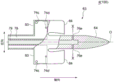
FIG. 6 is an axial partial cross-sectional view of an embodiment of a nozzle.
Fig. 7 is a sectional view VII-VII of the nozzle shown in fig. 6.
Fig. 8 is a sectional view VIII-VIII of the nozzle shown in fig. 6.
FIG. 9 is an axial partial cross-sectional view of an embodiment of a nozzle.
Fig. 10 is an X-X cross-sectional view of the nozzle shown in fig. 9.
Fig. 11 is a diagram showing a configuration of a fuel supply system of a combustor (combustion apparatus) according to an embodiment.
Fig. 12 is a diagram showing a configuration of a fuel supply system of a combustor (combustion apparatus) according to an embodiment.
Detailed Description
Several embodiments of the present invention will be described below with reference to the drawings. However, the dimensions, materials, shapes, relative arrangements, and the like of the components described as the embodiments and shown in the drawings are merely illustrative examples, and do not limit the scope of the present invention.
First, a gas turbine, which is an example of an application target of the combustion apparatus according to some embodiments, will be described with reference to fig. 1. Fig. 1 is a schematic configuration diagram showing a gas turbine 1 according to an embodiment of the present invention.
As shown in fig. 1, a gas turbine 1 according to an embodiment includes: a compressor 2 for generating compressed air as an oxidant; a combustor 4 (combustion apparatus 100) for generating combustion gas using compressed air and fuel; a turbine 6 driven to rotate by the combustion gas. In the case of the gas turbine 1 for power generation, a generator, not shown, is connected to the turbine 6, and power generation is performed by rotational energy of the turbine 6.
A specific configuration example of each part of the gas turbine 1 will be described.
The compressor 2 includes a compressor casing 10, an air intake port 12 provided on an inlet side of the compressor casing 10 and configured to take in air, a rotor 8 provided so as to penetrate both the compressor casing 10 and a turbine casing 22 described later, and various blades arranged in the compressor casing 10. The various blades include: an inlet guide vane 14 provided on the air intake port 12 side; a plurality of stationary blades 16 fixed to the compressor casing 10 side; a plurality of rotor blades 18 are implanted in the rotor 8 so as to be alternately arranged with the stator blades 16. The compressor 2 may include other components such as an extraction chamber, not shown. In the compressor 2, the air taken in from the air intake port 12 passes through and is compressed by the plurality of stationary blades 16 and the plurality of rotor blades 18, and becomes high-temperature and high-pressure compressed air. The high-temperature and high-pressure compressed air is sent from the compressor 2 to the combustor 4 at the rear stage.
The burner 4 is disposed within the housing 20. As shown in fig. 1, a plurality of combustors 4 may be arranged in a ring shape around the rotor 8 in the casing 20. The fuel and the compressed air generated by the compressor 2 are supplied to the combustor 4, and the fuel is combusted, thereby generating combustion gas as a working fluid of the turbine 6. And, the combustion gas is delivered from the combustor 4 to the turbine 6 at the rear stage. A detailed configuration example of the combustor 4 will be described later.
The turbine 6 includes a turbine casing 22 and various blades disposed in the turbine casing 22. The various blades include: a plurality of stationary blades 24 fixed to the turbine casing 22 side; a plurality of rotor blades 26 implanted in the rotor 8 are alternately arranged with the stator blades 24. The turbine 6 may include other components such as an outlet guide vane. In the turbine 6, the combustion gas passes through the plurality of stationary blades 24 and the plurality of moving blades 26, and the rotor 8 is rotationally driven. Thereby, the generator coupled to the rotor 8 is driven.
An exhaust chamber 30 is connected to the downstream side of the turbine chamber 22 via an exhaust chamber 28. The combustion gas having driven the turbine 6 is discharged to the outside through the exhaust chamber 28 and the exhaust chamber 30.
Next, a detailed configuration of the combustor 4 (combustion apparatus 100) according to an embodiment will be described with reference to fig. 2 and 3. Fig. 2 is a schematic view showing a combustor 4 (combustion apparatus 100) according to an embodiment. Fig. 3 is a sectional view showing a part of a burner 4 (combustion apparatus 100) according to an embodiment.
As shown in fig. 2 and 3, a plurality of combustors 4 (combustion apparatus 100) according to an embodiment are arranged in a ring shape around a rotor 8 (see fig. 1). Each combustor 4 includes: a combustor liner 46 provided in the combustor chamber 40 defined by the casing 20; a second combustion burner 50 and a plurality of first combustion burners 60 are disposed in the combustor liner 46. The combustor 4 may include other components such as a bypass pipe (not shown) for bypassing the combustion gas.
For example, the combustor liner 46 has: an inner tube 46a disposed around the second fuel burner 50 and the plurality of first burners 60; and a transition piece 46b coupled to a distal end portion of the inner tube 46 a.
The second fuel burner 50 is disposed along a central axis of the combustor liner 46. The plurality of first burners 60 are arranged so as to be separated from each other so as to surround the second fuel burners 50.
The second fuel burner 50 has: a second nozzle (nozzle) 54 connected to the fuel port 52; a cone 56 disposed so as to surround the second nozzle 54; and a swirler 58 disposed at an outer periphery of the second nozzle 54.
The first burner tip 60 has: a first nozzle (nozzle) 63 connected to the fuel port 62; a combustion liner (nozzle housing) 66 disposed so as to surround the first nozzle 63; an extension pipe 65 connecting the combustion liner 66 and the combustor liner 46 (for example, the inner tube 46 a); and a swirler 70 provided on the outer periphery of the first nozzle 63. The fuel ports 62 include at least two fuel ports 62a, 62 b. A first supply flow path and a second supply flow path (not shown) for supplying fuel are connected to the fuel ports 62a and 62b, respectively, so that the fuel from the first supply flow path can be supplied to the first nozzle 63 through the fuel port 62a, and the fuel from the second supply flow path can be supplied to the first nozzle 63 through the fuel port 62 b. The specific structure of the first burner tip 60 will be described later.
As shown in fig. 3, the extension pipe 65 extends from an upstream end surface connected to the combustion cylinder 66 to a downstream end surface (extension pipe outlet 65 a). Fig. 3 shows a flow path center line O' passing through the center of the extension pipe outlet 65 a.
As described below, the second fuel burner 50 may be a burner for generating a diffusion combustion flame, and the second nozzle 54 may be a nozzle for injecting fuel for diffusion combustion. Further, it is possible that the first burner 60 is a burner for burning a premixed gas, and the first nozzle 63 is a nozzle for injecting a premixed fuel.
That is, in the combustor 4 having the above-described configuration, the high-temperature and high-pressure compressed air generated by the compressor 2 is supplied into the combustor chamber 40 from the chamber inlet 42, and further flows into the combustion liner 66 from the combustor chamber 40. The compressed air and the fuel supplied from the fuel port 62 are premixed in the combustion cylinder 66. At this time, the premixed gas mainly forms a swirling flow by the swirler 70 and flows into the combustor liner 46. The compressed air is mixed with fuel injected from the second fuel burner 50 through the fuel port 52 in the combustor liner 46, and is ignited by a flame species not shown and burned to generate combustion gas. At this time, a part of the combustion gas is diffused into the surroundings along with the flame, and the premixed gas flowing into the combustor liner 46 from each first combustion nozzle 60 is ignited and burned. That is, the diffusion combustion flame of the fuel for diffusion combustion injected from the second fuel burner 50 can perform flame holding for stable combustion of the premixed gas (premixed fuel) from the first burner 60. At this time, the combustion region is formed in, for example, the inner tube 46 a.
Next, with reference to fig. 4 to 10, the configuration of the main portion of the burner 4 (combustion apparatus 100) according to an embodiment will be described using the first burner tip 60 described above as an example.
The burner tip of the present invention is not limited to the first burner tip 60, and any type of burner tip may be applied as long as a swirler (swirler vane) is provided in the axial flow path around the nozzle. For example, in one embodiment, the burner may be a type of burner that mainly performs diffusion combustion, such as the second fuel burner 50, provided in the combustor 4 of the gas turbine 1, or may be a type of burner provided in a facility other than the gas turbine 1.
That is, the nozzle of the present invention is not limited to the first nozzle 63. In one embodiment, the nozzle may be a second nozzle 54 disposed in a manner surrounded by a plurality of first nozzles 63. The nozzle of the present invention may be a nozzle for injecting a premixed fuel or a nozzle for injecting a fuel for diffusion combustion.
Fig. 4 is a main part sectional view including the first burner tip 60 of the burner 4 (combustion apparatus 100) according to the embodiment, and fig. 5 is a view in the direction a of the burner 4 (combustion apparatus 100) shown in fig. 4.
As shown in fig. 4 and 5, in the combustor 4 according to the embodiment, the first burner tip 60 includes a combustion liner (nozzle housing) 66 and a first nozzle 63. The combustion liner 66 defines an axial flow passage 68 of the first nozzle 63 in the axial direction by its inner peripheral surface, and the first nozzle 63 is provided in the axial flow passage 68. The first nozzle 63 includes: a cylindrical nozzle body 64 extending along an axial flow path 68; a swirler 70 comprising at least one swirler vane 72.
Here, the cylindrical shape is not limited to a cylindrical shape in a strict sense. That is, the nozzle body 64 may have a cylindrical shape at least in part, and a shape having a diameter varying in the central axis direction of the cylindrical shape, for example. For example, as shown in fig. 4, the nozzle body 64 may have a cylindrical shape in which one end portion in the central axis direction is tapered.
The combustion liner 66 is disposed concentrically with respect to the nozzle main body 64 and surrounds the first nozzle 63 including the nozzle main body 64 and the swirler vanes 72. That is, the axis of the combustion liner 66 substantially coincides with the axis O of the nozzle main body 64, and the diameter of the combustion liner 66 is larger than the diameter of the first nozzle 63.
In the axial flow passage 68 defined by the inner peripheral surface of the combustion cylinder 66, a gas (fluid) G such as compressed air flows from the upstream side (left side in fig. 4) toward the downstream side (right side in fig. 4).
The first nozzle 63 is connected to the fuel ports 62(62a, 62b) (see fig. 2 and 3), for example, as described above, and is supplied with fuel from the fuel ports 62(62a, 62 b). The fuel may be gas or liquid, and the type thereof is not particularly limited. The fuel supplied to the second nozzle 54 may be different from the fuel supplied to the first nozzle 63, and for example, oil fuel may be supplied to the second nozzle 54 and gas fuel such as natural gas may be supplied to the first nozzle 63.
The swirler 70 is configured to swirl gas flowing through the axial flow passage 68, and includes at least one swirler vane 72. The swirler 70 shown in fig. 4 and 5 exemplifies a case where six swirler vanes 72 are radially provided around the nozzle main body 64. However, in fig. 4, for the sake of simplicity, only two swirler vanes 72 arranged at positions of an angle of 0 degree and an angle of 180 degrees in the circumferential direction are shown (in the state of fig. 4, a total of four swirler vanes 72 are actually observed).
The swirler vanes 72 are provided in the axial flow passage 68 extending around the nozzle body 64 in the axial direction (the axial O direction) of the nozzle body 64 so as to protrude radially outward from the nozzle body 64 in the radial direction of the nozzle body 64, and are configured to swirl the gas flowing through the axial flow passage 68. The swirler vane 72 has: a ventral surface 81 as a pressure surface; a back surface 82 as a negative pressure surface; a leading edge 83 which is an upstream end in the gas flow direction (axial direction of the nozzle body 64); the trailing edge 84 is an end portion on the downstream side in the gas flow direction (the axial direction of the first nozzle 63).
A plurality of injection holes for injecting fuel are formed in the swirler vanes 72 and/or the nozzle body 64. The plurality of injection holes include: at least one first injection hole 74 opening at the surface of the swirler vane 72; at least one second injection hole 76 opening at a surface of swirler vane 72 or nozzle body 64. In the example shown in fig. 4 to 5, the first injection holes 74a and 74b are formed in the ventral surface 81 of the swirler vane 72 as the first injection hole 74, the first injection holes 74c and 74d are formed in the rear surface 82 of the swirler vane 72, the second injection holes 76a and 76b are formed in the ventral surface 81 of the swirler vane 72 as the second injection hole 76, and the second injection holes 76c and 76d are formed in the rear surface 82 of the swirler vane 72.
The first injection hole 74 and the second injection hole 76 communicate with a first fuel flow path 78 and a second fuel flow path 79 (see fig. 6 and 9, which will be described later) provided in the nozzle main body 64, respectively. The fuel injected from the first injection holes 74 and the second injection holes 76 is mixed with a gas (for example, compressed air as an oxidizing agent) to be a premixed gas (fuel gas), and is delivered to the combustor liner 46 to be combusted.
Fig. 6 and 9 are partial sectional views in the axial direction of the nozzle according to the embodiment, fig. 7 is a sectional view from VII to VII of the nozzle shown in fig. 6, fig. 8 is a sectional view from VIII to VIII of the nozzle shown in fig. 6, and fig. 10 is a sectional view from X to X of the nozzle shown in fig. 9, respectively.
In the embodiment shown in fig. 6 to 8, as in the example shown in fig. 4 to 5, the first injection holes 74a and 74b are formed in the ventral surface 81 of the swirler vane 72 as the first injection hole 74, the first injection holes 74c and 74d are formed in the rear surface 82 of the swirler vane 72, the second injection holes 76a and 76b are formed in the ventral surface 81 of the swirler vane 72 as the second injection hole 76, and the second injection holes 76c and 76d are formed in the rear surface 82 of the swirler vane 72.
In the embodiment shown in fig. 9 to 10, two first injection holes 74a and 74b are formed in the ventral surface 81 of the swirler vane 72 as the first injection holes 74, two first injection holes 74c and 74d are formed in the rear surface 82 of the swirler vane 72, and three second injection holes 76e are formed in the nozzle body as the second injection holes 76. As shown in fig. 9 and 10, the three second injection holes 76e are provided at substantially equal intervals in the circumferential direction of the nozzle body 64. That is, in the axially orthogonal cross section (see fig. 10), the axial center O is provided at intervals of about every 120 degrees.
Hereinafter, the first ejection holes 74 are represented by the first ejection holes 74a to 74d, and the second ejection holes 76a to 76e are represented by the first ejection holes 74.
As shown in fig. 6 and 9, a first fuel flow path 78 and a second fuel flow path 79, which extend in the axial direction of the nozzle body 64, are provided in the nozzle body 64, respectively. For example, as shown in FIG. 6, a portion of the first and second fuel flow paths 78, 79 may extend radially of the nozzle body 64 within the swirler vanes 72.
The first fuel flow path 78 communicates with the first injection holes 74, and the second fuel flow path 79 communicates with the second injection holes 76.
The same fuel may be supplied to the first fuel flow path 78 and the second fuel flow path 79, or different types of fuel may be supplied to them. Further, the fuel may be supplied as a gas to the first fuel flow path 78 and the second fuel flow path 79, or the fuel may be supplied as a liquid to the first fuel flow path 78 and the second fuel flow path 79. The gaseous fuel may be supplied to both the first fuel flow path 78 and the second fuel flow path 79, the liquid fuel may be supplied to both the first fuel flow path 78 and the second fuel flow path 79, or the gaseous fuel may be supplied to one of the first fuel flow path 78 and the second fuel flow path 79 and the liquid fuel may be supplied to the other.
In this way, since the first fuel flow path 78 and the second fuel flow path 79 communicating with the first injection hole 74 and the second injection hole 76, respectively, through which the fuel is injected are provided, the design of the first fuel flow path 78 and the first injection hole 74 can be adapted to the property of the fuel flowing through the first fuel flow path 78, and the design of the second fuel flow path 79 and the second injection hole 76 can be adapted to the property of the fuel flowing through the second fuel flow path 79.
In several embodiments, the total area of first jet orifices 74 is greater than the total area of second jet orifices 76. Here, the total area of the first injection holes 74 refers to the sum of the opening areas or the flow passage areas of all the first injection holes 74, and the total area of the second injection holes 76 refers to the sum of the opening areas or the flow passage areas of all the second injection holes 76.
For example, in the embodiment shown in fig. 6, the total opening area of the four first injection holes 74a to 74d provided in the swirler vane 72 is larger than the total opening area of the four second injection holes 76a to 76d provided in the swirler vane 72. In the embodiment shown in fig. 9, the total opening area of the four first injection holes 74a to 74d provided in the swirler vanes 72 is larger than the total opening area of the three second injection holes 76e provided in the nozzle main body 64.
In this way, since the total area of the first injection holes 74 is larger than the total area of the second injection holes 76, the flow rate of the fuel injected from the first injection holes 74 is relatively large compared to the second injection holes 76. Therefore, when the fuel is injected from the first injection hole 74, the differential pressure before and after the first injection hole is easily maintained. On the other hand, since the total area of the second injection holes 76 is smaller than the total area of the first injection holes 74, the differential pressure between the front and rear of the second injection holes 76 is easily maintained although the flow rate of the fuel injected from the second injection holes 76 is relatively small. This makes it easy to maintain the differential pressure between before and after the fuel injection in the combustion apparatus 100.
In some embodiments, the flow path area of the first fuel flow path 78 is larger than the flow path area of the second fuel flow path 79.
For example, in the embodiment shown in fig. 6, the flow passage area of the first fuel flow passage 78 in the cross section (see fig. 7) of the nozzle body 64 perpendicular to the axis is larger than the flow passage area of the second fuel flow passage 79 at the nozzle body 64 on the upstream side of the swirler vanes 72 in the flow direction of the fluid in the axial flow passage 68 (see fig. 4). In the embodiment shown in fig. 9 as well, the flow passage area of the first fuel flow passage 78 is larger than the flow passage area of the second fuel flow passage 79 in the nozzle body 64.
In the embodiment shown in fig. 6, the swirler vanes 72 have a larger flow area of the first fuel flow path 78 than the flow area of the second fuel flow path 79 in the cross section of the nozzle body 64 in the axial direction (see fig. 8).
Since the flow passage area of the first fuel flow passage 78 is larger than the flow passage area of the second fuel flow passage 79, the flow rate of the fuel injected from the first injection holes 74 is larger than that of the second injection holes 76. Therefore, when the fuel is injected from the first injection hole 74, the differential pressure is easily maintained before and after the first injection hole. On the other hand, since the flow passage area of the second fuel flow passage 79 is smaller than the flow passage area of the first fuel flow passage 78, the differential pressure between the front and rear of the second injection holes 76 is easily maintained although the flow rate of the fuel injected from the second injection holes 76 is relatively small. This makes it easy to maintain the differential pressure between before and after the fuel injection in the combustion apparatus 100.
In some embodiments, the ratio of the flow area ratio of the first fuel flow path 78 to the second fuel flow path 79 to the total injection hole area ratio of the first injection hole 74 to the second injection hole 76 (flow area ratio/total injection hole area ratio) is 0.8 or more and 1.2 or less.
For example, in the embodiment shown in fig. 6, if the total injection hole area ratio (the total area of the first injection holes 74/the total area of the second injection holes 76) which is the ratio of the total area of the first injection holes 74(74a to 74d) to the total area of the second injection holes 76(76a to 76d) is 2, the diameters of the first injection holes 74 and the second injection holes 76, the flow paths of the first fuel flow path 78 and the second fuel flow path 79, and the like are set so that the flow path area ratio (the flow path area of the first fuel flow path 78/the flow path area of the second fuel flow path 79) which is the ratio of the flow path area of the first fuel flow path 78 to the flow path area of the second fuel flow path 79 becomes 1.6 to 2.4.
Since the ratio of the flow passage area ratio to the total injection hole area ratio is close to 1 in this way, the pressure loss in the first fuel flow passage 78 and the second fuel flow passage 79 can be reduced, and therefore, the differential pressure between before and after the fuel injection can be easily maintained in the combustion apparatus 100.
In some embodiments, as shown in fig. 4 to 6, 8, and 9, the first injection holes 74 are provided upstream of the second injection holes 76 in the flow direction of the fluid in the axial flow passage 68.
In this way, when the first injection hole 74 is provided at a position upstream of the second injection hole 76, the mixing distance of the fuel injected from the first injection hole 74 and the fuel injected from the second injection hole 76 with the air flowing from the upstream side in the axial flow passage 68 can be increased by the distance between the first injection hole 74 and the second injection hole 76. Therefore, mixing (premixing) of the fuel and air injected from the first injection holes 74 can be further promoted, and good combustion efficiency can be obtained in the combustion apparatus 100.
In the embodiment in which the nozzle main body 64 or the swirler vanes 72 have the plurality of first injection holes 74 or the plurality of second injection holes 76 formed therein, the plurality of first injection holes 74 and/or the plurality of second injection holes 76 may be arranged at different positions from each other in the axial direction or the radial direction of the nozzle main body 64. Hereinafter, the axial direction of the nozzle body 64 and the radial direction of the nozzle body 64 may be simply referred to as the axial direction and the radial direction, respectively.
In several embodiments, the radial position of at least one of the plurality of first injection holes 74 and at least one of the plurality of second injection holes 76 may be substantially the same.
For example, in the example shown in fig. 4 or 6, the radial positions of the first injection holes 74a, 74c located on the relatively outer diameter side of the plurality of first injection holes 74 are substantially the same as the radial positions of the second injection holes 76a, 76c located on the relatively outer diameter side of the plurality of second injection holes 76 (i.e., the distances from the central axis of the nozzle main body 64 are substantially the same). In this example, the radial positions of the first injection holes 74b, 74d, which are positioned on the relatively inner diameter side, of the plurality of first injection holes 74 are substantially the same as the radial positions of the second injection holes 76b, 76d, which are positioned on the relatively inner diameter side, of the plurality of second injection holes 76 (that is, the distances from the central axis of the nozzle body 64 are substantially the same).
In the embodiment shown in fig. 6 and 9, as described above, the swirler vanes 72 include the four first injection holes 74 in total including the first injection holes 74a and 74b formed in the ventral surface 81 and the first injection holes 74c and 74d formed in the rear surface 82. Of the two first injection holes 74a and 74b formed in the ventral surface 81, the first injection hole 74a is arranged radially outward, and the first injection hole 74b is arranged radially inward. Of the two first injection holes 74c and 74d formed in the back surface 82, the first injection hole 74c is disposed radially outward, and the first injection hole 74d is disposed radially inward. The first injection holes 74a and the first injection holes 74c may be arranged at the same positions in the radial direction. The first injection holes 74b and 74d may be arranged at the same positions in the radial direction.
In the embodiment shown in fig. 6, the plurality of second injection holes 76a, 76b, 76c, and 76d formed in the swirler vanes 72 are also arranged at different positions in the radial direction, as in the case of the first injection holes 74a, 74b, 74c, and 74 d.
In this way, the plurality of first injection holes 74 or the plurality of second injection holes 76 are arranged at different positions in the radial direction of the nozzle main body 64, whereby the flow of the fuel in the first fuel flow path 78 becomes smooth. Therefore, the fuel can be smoothly supplied from the first injection hole 74.
In the embodiment in which the nozzle main body 64 or the swirler vanes 72 include the plurality of first injection holes 74 or the plurality of second injection holes 76, an outer injection hole of the plurality of first injection holes 74 and/or the plurality of second injection holes 76 that is arranged on the outer side in the radial direction may be arranged on the upstream side (i.e., the left-hand side in fig. 4, 6, and 9) in the flow direction of the gas G in the axial flow passage 68 (see fig. 4) than an inner injection hole that is arranged on the inner side in the radial direction.
In the embodiment shown in fig. 6 and 9, of the first injection holes 74a and 74b formed in the ventral surface 81 of the swirler vane 72, the first injection hole 74a, which is the outer injection hole, is disposed upstream in the flow direction of the gas G in the axial flow passage 68 (see fig. 4) than the first injection hole 74b, which is the inner injection hole. Of the first injection holes 74c and 74d formed in the back surface 82 of the swirler vane 72, the first injection hole 74c serving as the outer injection hole is disposed on the upstream side in the flow direction of the gas G in the axial flow passage 68 (see fig. 4) than the first injection hole 74d serving as the inner injection hole.
In the embodiment shown in fig. 6, the plurality of second injection holes 76a, 76b, 76c, and 76d formed in the swirler vanes 72 are also arranged at axially different positions, as in the case of the first injection holes 74a, 74b, 74c, and 74 d.
As described above, by disposing the outer jet hole of the plurality of first jet holes 74 or the plurality of second jet holes 76 on the upstream side of the inner jet hole in the flow direction of the gas G in the axial flow passage 68, the mixing of the fuel and the air injected from the outer jet hole provided on the outer peripheral side where the flow passage area of the air is relatively wide can be further promoted in the axial flow passage 68, and therefore, more favorable combustion efficiency can be obtained.
In the embodiment in which the nozzle main body 64 or the swirler vanes 72 include the plurality of first injection holes 74 or the plurality of second injection holes 76, the outer injection holes of the plurality of first injection holes 74 and/or the plurality of second injection holes 76 arranged on the outer side in the radial direction have a larger hole diameter than the inner injection holes arranged on the inner side in the radial direction.
In the embodiment shown in fig. 6 and 9, of the first injection holes 74a and 74b formed in the ventral surface 81 of the swirler vane 72, the hole diameter d1 of the first injection hole 74a, which is the outer injection hole, is larger than the hole diameter d2 of the first injection hole 74b, which is the inner injection hole. Of the first injection holes 74c and 74d formed in the rear surface 82 of the swirler vane 72, the diameter d3 of the first injection hole 74c, which is the outer injection hole, is larger than the diameter d4 of the first injection hole 74d, which is the inner injection hole.
In the embodiment shown in fig. 6, the plurality of second injection holes 76a, 76b, 76c, and 76d formed in the swirler vanes are also larger in the diameter d5 of the second injection hole 76a and the diameter d7 of the second injection hole 76c, which are the outer injection holes, than in the diameter d6 of the second injection hole 76b and the diameter d8 of the second injection hole 76d, which are the inner injection holes, respectively.
In this way, the outer injection holes of the plurality of first injection holes 74 or the plurality of second injection holes 76 have a larger diameter than the inner injection holes, and the flow rate of the fuel injected from the outer injection holes is increased, so that more fuel can be injected from the outer injection holes to promote mixing with air, and thus, more favorable combustion efficiency can be obtained.
Next, the configuration of the fuel supply system of the combustor 4 (combustion apparatus 100) according to an embodiment will be described with reference to fig. 11 and 12. Fig. 11 and 12 are diagrams each showing a configuration of a fuel supply system of the combustor 4 (combustion apparatus 100) according to an embodiment, and these diagrams show a supply system of fuel to be supplied to the first nozzle 63.
In some embodiments, as shown in fig. 11 and 12, a combustion apparatus 100 including a combustor 4 includes: a first supply flow path 86 connected to the first fuel flow path 78 of the first nozzle 63; and a second supply passage 88 connected to the second fuel passage 79 of the first nozzle 63. The first and second supply passages 86, 88 allow the first and/or second fuel from the first and/or second fuel tanks 96, 98 to flow therethrough.
The first supply flow path 86 is provided with a flow rate adjustment valve 92 capable of adjusting the flow rate of the fuel flowing through the first supply flow path 86, and the fuel at an arbitrary flow rate can be supplied to the first fuel flow path 78 via the flow rate adjustment valve 92. The second supply passage 88 is provided with a flow rate adjustment valve 94 capable of adjusting the flow rate of the fuel flowing through the second supply passage 88, and the fuel at an arbitrary flow rate can be supplied to the second fuel passage 79 via the flow rate adjustment valve 94.
The first supply channel 86 and the second supply channel 88 are provided with flow meters 93 and 95.
In the embodiment shown in fig. 11, the fuel heater 101 is provided in the first supply passage 86, and the first fuel is heated to a predetermined temperature by the fuel heater (FGH)101, then flows through the first supply passage 86, and is supplied to the first fuel passage 78 of the first nozzle 63 through, for example, the fuel port 62a (see fig. 2 and 3). A fuel heater (FGH)102 is provided in the second supply passage 88, and the second fuel is heated to a predetermined temperature by the fuel heater 102, flows through the second supply passage 88, and is supplied to the second fuel passage 79 of the first nozzle 63 via, for example, the fuel port 62b (see fig. 2 and 3).
The fuel supplied from the first supply channel 86 and the second supply channel 88 to the first fuel channel 78 and the second fuel channel 79 of the first nozzle 63 via the fuel ports 62a and 62b corresponds to "premixed fuel" in fig. 2.
In some embodiments, the first fuel supplied to the first fuel flow path 78 has a smaller heating value than the second fuel supplied to the second fuel flow path 79.
In this case, the first fuel flow path 78 and the first injection hole 74 of the first nozzle 63 can be designed to be suitable for the properties of the first fuel (low-calorie fuel) having a relatively small heat generation amount, and the second fuel flow path 79 and the second injection hole 76 can be designed to be suitable for the properties of the second fuel (high-calorie fuel) having a relatively large heat generation amount.
For example, the total area of the first injection holes 74 may be made larger than the total area of the second injection holes 76. In this case, the flow rate of the first fuel (low-calorie fuel) injected from the first injection holes 74 is relatively large, and the total area of the second injection holes 76 is relatively small, so that it is easy to maintain the differential pressure between the front and rear of the second injection holes 76 of the second fuel (high-calorie fuel) whose injection flow rate is relatively small. Therefore, the differential pressure between before and after the fuel injection is easily maintained in the combustion apparatus 100.
The total area ratio, which is the ratio of the total area of the first injection holes 74 to the total area of the second injection holes 76, may be determined based on a heat generation amount ratio, which is the ratio of the heat generation amount of the first fuel to the heat generation amount of the second fuel. For example, the total area of the first ejection holes 74 and the total area of the second ejection holes 76 may be determined so that the total area ratio is the reciprocal of the heat generation amount ratio.
This reduces the variation in the combustion heat between the use of the first fuel (low calorie fuel) and the use of the second fuel (high calorie fuel), and enables stable combustion of the fuel even when the first fuel (low calorie fuel) and the second fuel (high calorie fuel) are switched to be used.
For example, the first injection holes 74 may be provided upstream of the second injection holes 76. In this case, with respect to the first fuel (low calorie fuel) of a relatively large flow rate injected from the first injection hole 74, the mixing distance with the air flowing from the upstream side in the axial flow path 68 can be made longer by the distance amount between the first injection hole 74 and the second injection hole 76, as compared with the second fuel (high calorie) of a relatively small flow rate injected from the second injection hole 76. Therefore, the mixing (premixing) of the first fuel (low-calorie fuel) injected from the first injection holes 74 at a relatively large flow rate and the air can be further promoted, and the combustion efficiency of the entire combustion apparatus 100 can be improved.
In the embodiment shown in fig. 12, the first supply channel 86 and the second supply channel 88 are connected to a MIXER (MIXER)91 via a mixed fuel line 116. The first fuel and the second fuel flow into the mixer 91, and the first fuel and the second fuel are mixed in the mixer 91 to generate a mixed fuel.
The fuel heater 104 is provided in the mixed fuel line 116, and the mixed fuel generated by the mixer 91 is heated to a predetermined temperature by the fuel heater 104 in the mixed fuel line 116, then flows through the first supply passage 86, is supplied to the first fuel passage 78 of the first nozzle 63 via, for example, the fuel port 62a (see fig. 2 and 3), flows through the second supply passage 88, and is supplied to the second fuel passage 79 of the first nozzle 63 via, for example, the fuel port 62b (see fig. 2 and 3).
In the mixed fuel line 116, a calorimeter 115 for measuring the amount of heat of the mixed fuel flowing from the mixer 91 to the fuel heater 104 is provided between the mixer 91 and the fuel heater 104.
Here, the flow rate control valve 92 and the flow rate control valve (second valve) 94 provided in the first supply flow path 86 and the second supply flow path 88 are valves capable of controlling the flow rate of the mixed fuel supplied to the first fuel flow path 78 and the second fuel flow path 79, respectively.
In this embodiment, the mixed fuel obtained by mixing the first fuel and the second fuel can be supplied to the first fuel flow path 78 and the second fuel flow path 79, and the flow rate of the mixed fuel supplied to the second fuel flow path 79 can be adjusted by a flow rate adjustment valve (second valve) 94. Thus, the flow rate of the mixed fuel in the second fuel flow path 79 is adjusted by the flow rate adjustment valve (second valve) 94, whereby the flow rate of the whole mixed fuel can be adjusted.
Here, the first fuel and the second fuel may have different heat generation amounts from each other. In this case, the opening degree of the flow rate adjustment valve (second valve) 94 may be adjusted according to the mixing ratio of the first fuel and the second fuel in the mixed fuel.
In this case, the flow rate of the entire mixed fuel can be appropriately adjusted according to the mixing ratio of the first fuel and the second fuel.
The mixing ratio of the mixed fuel can be adjusted by adjusting the flow rates of the first fuel and the second fuel flowing into the mixer 91 by a flow rate adjustment valve or the like. Alternatively, the mixing ratio of the mixed fuel may be grasped from the measurement result of the calorimeter 115.
For example, when the content of the first fuel in the mixed fuel is large and the calorific value of the mixed fuel is relatively small, the mixed fuel may be supplied to both the first fuel flow path 78 and the second fuel flow path 79 with the opening degree of the flow rate adjustment valve (second valve) 94 increased in order to obtain a large flow rate. When the content of the second fuel in the mixed fuel is large and the calorific value of the mixed fuel is relatively large, the mixed fuel is mainly supplied to the first fuel flow path 78 so that the flow rate is relatively small and the opening degree of the flow rate adjustment valve (second valve) 94 is reduced to reduce the flow rate of the second fuel flow path 79.
In this case, when the first injection hole 74 is provided upstream of the second injection hole 76 in the flow direction of the fluid in the axial flow passage 68, the mixed fuel can be supplied to the first fuel flow passage 78 at all times while maintaining the opening degree of the flow rate adjustment valve 92 regardless of the mixture ratio of the mixed fuel. In this case, the mixed fuel injected at all times regardless of the mixture ratio of the mixed fuel (i.e., the mixed fuel injected from the first injection hole 74) can be kept at a relatively long mixing distance with the air flowing from the upstream side in the axial flow passage 68, and thus the mixing (premixing) of the fuel and the air can be further promoted.
In the embodiment shown in fig. 12, since the mixed fuel obtained by mixing the first fuel and the second fuel is supplied to the first fuel flow path 78 and the second fuel flow path 79, a heater for heating the fuel may be provided as long as the mixed fuel is heated. That is, the heater for heating the mixed fuel is sufficient only for the fuel heater 104 provided in the mixed fuel line 116. Therefore, the cost can be reduced as compared with the case where the heaters are provided separately for the first fuel and the second fuel.
In some embodiments, the first fuel and the second fuel may be supplied to the first nozzle 63 and may be supplied to a nozzle other than the first nozzle 63.
For example, in one embodiment, the first fuel and the second fuel are supplied to the first nozzle 63, and are also supplied to the second nozzle 54 (see fig. 2 and 3).
Alternatively, in one embodiment, the first fuel and the second fuel may be supplied to the first nozzle 63, and may be supplied to a third nozzle (for example, a top hat nozzle (not shown)) which is a nozzle different from the first nozzle and the second nozzle.
In the embodiment shown in fig. 11 and 12, the first fuel and the second fuel are supplied to the second nozzle 54 (see fig. 2 and 3) as fuel for diffusion combustion.
In the example shown in fig. 11, a mixer 90 is provided in branch lines 118 and 119 branching from the first supply channel 86 and the second supply channel 88, and the mixer 90 and the second nozzle 54 are connected via a diffusion combustion fuel supply channel 120. The branch lines 118 and 119 are provided with valves 106 and 107 for adjusting the flow rates of the first fuel and the second fuel flowing into the mixer 90. The diffusion combustion fuel supply passage 120 is provided with a valve 108 and a flow meter 109 for adjusting the flow rate of the diffusion combustion fuel supplied from the mixer 90 to the second nozzle 54.
The first fuel and the second fuel from the first fuel tank 96 and the second fuel tank 98 are heated by the fuel heaters 101 and 102, and then flow into the mixer 90 through branch lines 118 and 119, and are mixed in the mixer 90 to be a mixed fuel. The mixed fuel thus obtained is supplied from the diffusion combustion fuel supply passage 120 to the second nozzle 54 via, for example, the fuel port 52.
In the example shown in fig. 12, the mixed fuel line 116 and the second nozzle 54 are connected via a diffusion combustion fuel supply passage 120. The mixed fuel (a mixture of the first fuel and the second fuel) flowing through the mixed fuel line 116 is supplied to the second nozzle 54 via the diffusion combustion fuel supply passage 120. The diffusion combustion fuel supply passage 120 is provided with a valve 108 and a flow meter 109 for adjusting the flow rate of the diffusion combustion fuel supplied from the mixed fuel line 116 to the second nozzle 54.
In some embodiments, either the first fuel or the second fuel may be supplied separately to the second nozzle 54 or the third nozzle (a nozzle other than the first nozzle 63 and the second nozzle 54 such as a top hat nozzle), or another fuel different from the first fuel and the second fuel may be supplied.
The embodiments of the present invention have been described above, but the present invention is not limited to the above embodiments, and includes a modification of the above embodiments or an appropriate combination of the above embodiments.
In the present specification, expressions indicating relative or absolute arrangements such as "in a certain direction", "along a certain direction", "parallel", "orthogonal", "central", "concentric" or "coaxial" indicate not only such arrangements in a strict sense but also a state of being relatively displaced with a tolerance or an angle or a distance to an extent that the same function can be obtained.
For example, expressions indicating states in which objects are equal, such as "identical", "equal", and "homogeneous", indicate not only states in which the objects are equal in a strict sense but also states in which there is a tolerance or a difference in the degree to which the same function can be obtained.
In the present specification, the expression "a shape such as a quadrangular shape or a cylindrical shape" means not only a shape such as a strictly quadrangular shape or a cylindrical shape in terms of geometry but also a shape including a concave-convex portion, a chamfered portion, and the like within a range in which the same effect is obtained.
In the present specification, the expression "including", "including" or "having" one structural element is not an exclusive expression excluding the presence of other structural elements.
Description of the reference numerals
1 gas turbine
2 compressor
4 burner
6 turbine
8 rotor
10 compressor chamber
12 air intake
14 inlet guide vane
16 stationary blade
18 bucket
20 casing
22 turbine chamber
24 stator vane
26 bucket
28 exhaust machine room
30 air exhaust chamber
40 combustor chamber
42 machine room entrance
46 combustor liner
46a inner cylinder
46b tail tube
50 second fuel burner
52 fuel port
54 second nozzle
56 taper
58 swirler
60 first burner
62 fuel port
63 first nozzle
64 nozzle body
65 extension pipe
65a extension tube outlet
66 combustion cylinder
68 axial flow path
70 cyclone
72 swirler vane
74. 74 a-74 d first injection hole
76. 76a to 76e second injection hole
78 first fuel flow path
79 second fuel flow path
81 abdomen noodles
82 back side
83 leading edge
84 trailing edge
86 first supply flow path
88 second supply flow path
90 mixer
91 mixer
92 flow control valve
93 flow meter
94 flow regulating valve
95 flow meter
100 combustion device
101 fuel heater
102 fuel heater
104 fuel heater
106 valve
107 valve
108 valve
109 flow meter
115 calorimeter
116 mixed fuel line
118 branch line
119 branch line
120 diffusion combustion fuel supply flow path
Claims (11)
1. A combustion apparatus is provided with:
a nozzle provided in an axial flow path and configured to inject a premixed fuel including a first fuel and a second fuel into the axial flow path; and
a nozzle housing including a combustion cylinder disposed so as to surround the nozzle and defining the axial flow path for premixing the premixed fuel and air from the nozzle to obtain a premixed gas,
the nozzle surrounded by the combustion can includes:
a cylindrical nozzle body extending along the axial flow path;
a swirler vane configured to protrude radially outward from the nozzle body in a radial direction of the nozzle body and swirl a fluid flowing through the axial flow passage;
at least one first injection hole opened at a surface of the swirler vane for injecting the first fuel;
at least one second injection hole that is open on the surface of the nozzle body at a position downstream of the first injection hole in the flow direction of the fluid in the axial flow path and injects the second fuel;
a first fuel flow path extending inside the nozzle body and communicating with the at least one first injection hole; and
a second fuel flow path extending inside the nozzle body independently of the first fuel flow path, communicating with the at least one second injection hole,
the combustion device is characterized in that,
the combustion apparatus further includes:
a first supply flow path capable of supplying the first fuel to the first fuel flow path; and
a second supply flow path capable of supplying the second fuel different from the first fuel to the second fuel flow path,
the first fuel has a smaller heating value than the second fuel,
the ratio of the total area of the first injection holes to the total area of the second injection holes is determined according to the ratio of the heat generation amount of the first fuel to the heat generation amount of the second fuel.
2. The combustion apparatus as claimed in claim 1,
the total area of the first injection holes is larger than the total area of the second injection holes.
3. The combustion apparatus as claimed in claim 2,
the first fuel flow path has a larger flow area than the second fuel flow path.
4. The combustion apparatus as claimed in claim 3,
a ratio of a flow area ratio to a total area ratio of the first injection holes to a total area of the second injection holes, that is, the flow area ratio/the total area ratio of the injection holes is 0.8 or more and 1.2 or less, the flow area ratio being a ratio of the flow area of the first fuel flow path to the flow area of the second fuel flow path, and the total area ratio of the injection holes being a ratio of the total area of the first injection holes to the total area of the second injection holes.
5. The combustion apparatus as claimed in claim 1,
the nozzle body or the swirler vane has at least two of the first injection holes or at least two of the second injection holes,
the at least two first injection holes or the at least two second injection holes are arranged at different positions from each other in a radial direction of the nozzle body.
6. The combustion apparatus as claimed in claim 5,
among the at least two first injection holes or the at least two second injection holes, an outer injection hole arranged on the outer side in the radial direction is arranged on the upstream side in the flow direction of the fluid in the axial flow passage than an inner injection hole arranged on the inner side in the radial direction.
7. The combustion apparatus as claimed in claim 5 or 6,
among the at least two first injection holes or the at least two second injection holes, an outer injection hole arranged on the outer side in the radial direction has a larger hole diameter than an inner injection hole arranged on the inner side in the radial direction.
8. The combustion apparatus as claimed in claim 1,
the combustion apparatus further includes:
a mixer that can mix a first fuel and a second fuel having mutually different heat generation amounts to generate a mixed fuel;
a first supply flow path capable of supplying the mixed fuel to the first fuel flow path;
a second supply flow path capable of supplying the mixed fuel to the second fuel flow path; and
and a second valve provided in the second supply flow path and capable of adjusting a flow rate of the mixed fuel supplied to the second fuel flow path.
9. The combustion apparatus as claimed in claim 8,
the combustion apparatus further includes a heater capable of heating the mixed fuel generated by the mixer,
the first supply flow path is configured to supply the mixed fuel heated by the heater to the first fuel flow path,
the second supply flow path is configured to supply the mixed fuel heated by the heater to the second fuel flow path.
10. The combustion apparatus as claimed in claim 8 or 9,
the opening degree of the second valve is adjusted according to a mixing ratio of the first fuel and the second fuel in the mixed fuel.
11. A gas turbine engine, characterized in that,
the gas turbine is provided with:
a compressor for generating compressed air;
the combustion apparatus according to claim 1, configured to generate combustion gas by combusting fuel injected from at least one of the at least one first fuel injection hole and the at least one second fuel injection hole by the compressed air from the compressor; and
and a turbine configured to be driven by the combustion gas from the combustion apparatus.
Applications Claiming Priority (3)
| Application Number | Priority Date | Filing Date | Title |
|---|---|---|---|
| JP2016040951A JP6626743B2 (en) | 2016-03-03 | 2016-03-03 | Combustion device and gas turbine |
| JP2016-040951 | 2016-03-03 | ||
| PCT/JP2017/007026 WO2017150364A1 (en) | 2016-03-03 | 2017-02-24 | Combustion device and gas turbine |
Publications (2)
| Publication Number | Publication Date |
|---|---|
| CN108700298A CN108700298A (en) | 2018-10-23 |
| CN108700298B true CN108700298B (en) | 2021-03-19 |
Family
ID=59742955
Family Applications (1)
| Application Number | Title | Priority Date | Filing Date |
|---|---|---|---|
| CN201780014987.4A Active CN108700298B (en) | 2016-03-03 | 2017-02-24 | Combustion apparatus and gas turbine |
Country Status (5)
| Country | Link |
|---|---|
| US (1) | US20190093570A1 (en) |
| JP (1) | JP6626743B2 (en) |
| CN (1) | CN108700298B (en) |
| SA (1) | SA518392299B1 (en) |
| WO (1) | WO2017150364A1 (en) |
Families Citing this family (10)
| Publication number | Priority date | Publication date | Assignee | Title |
|---|---|---|---|---|
| US20180135532A1 (en) * | 2016-11-15 | 2018-05-17 | General Electric Company | Auto-thermal fuel nozzle flow modulation |
| KR102164619B1 (en) * | 2019-04-08 | 2020-10-12 | 두산중공업 주식회사 | Combuster and gas turbine having the same |
| JP7200077B2 (en) * | 2019-10-01 | 2023-01-06 | 三菱重工業株式会社 | Gas turbine combustor and its operation method |
| JP7349403B2 (en) * | 2020-04-22 | 2023-09-22 | 三菱重工業株式会社 | Burner assembly, gas turbine combustor and gas turbine |
| CN113251439B (en) * | 2021-06-24 | 2021-11-16 | 成都中科翼能科技有限公司 | Double-stage co-rotating head device for dual-fuel gas turbine |
| CN113701194B (en) * | 2021-08-16 | 2022-11-22 | 中国航发沈阳发动机研究所 | Premixing device for combustion chamber of gas turbine |
| KR102522143B1 (en) * | 2021-09-16 | 2023-04-13 | 두산에너빌리티 주식회사 | Fuel supply system for combustor |
| KR102522144B1 (en) * | 2021-09-16 | 2023-04-13 | 두산에너빌리티 주식회사 | Fuel supply system for combustor |
| CN114738796A (en) * | 2022-03-09 | 2022-07-12 | 西北工业大学 | Air atomizing nozzle with rotary oil pipe |
| DE102022207492A1 (en) * | 2022-07-21 | 2024-02-01 | Rolls-Royce Deutschland Ltd & Co Kg | Nozzle device for adding at least one gaseous fuel and one liquid fuel, set, supply system and gas turbine arrangement |
Citations (4)
| Publication number | Priority date | Publication date | Assignee | Title |
|---|---|---|---|---|
| CN101055093A (en) * | 2006-04-14 | 2007-10-17 | 三菱重工业株式会社 | Premixing combustion mouth for gas turbine |
| JP2008116200A (en) * | 2006-10-31 | 2008-05-22 | Korea Electric Power Corp | Combustor, multi-combustor, and combustion method |
| CN102165253A (en) * | 2008-09-26 | 2011-08-24 | 西门子能源公司 | Flex-fuel injector for gas turbines |
| JP2014020769A (en) * | 2012-07-24 | 2014-02-03 | Hitachi Ltd | Gas turbine combustor |
Family Cites Families (9)
| Publication number | Priority date | Publication date | Assignee | Title |
|---|---|---|---|---|
| US5680766A (en) * | 1996-01-02 | 1997-10-28 | General Electric Company | Dual fuel mixer for gas turbine combustor |
| JP3742722B2 (en) * | 1998-03-16 | 2006-02-08 | 財団法人電力中央研究所 | Gas turbine combustor |
| CN1242201C (en) * | 2001-07-10 | 2006-02-15 | 三菱重工业株式会社 | Premixing nozzle, burner and gas turbine |
| KR100872841B1 (en) * | 2007-09-28 | 2008-12-09 | 한국전력공사 | A fuel nozzle of gas turbine combustor for dme and its design method |
| US20110005189A1 (en) * | 2009-07-08 | 2011-01-13 | General Electric Company | Active Control of Flame Holding and Flashback in Turbine Combustor Fuel Nozzle |
| JP2011099654A (en) * | 2009-11-09 | 2011-05-19 | Mitsubishi Heavy Ind Ltd | Combustion burner for gas turbine |
| CA2896463A1 (en) * | 2012-12-28 | 2014-07-03 | General Electric Company | Turbine engine assembly comprising a cryogenic fuel system |
| JP6285807B2 (en) * | 2014-06-04 | 2018-02-28 | 三菱日立パワーシステムズ株式会社 | Gas turbine combustor |
| CN204358774U (en) * | 2014-09-03 | 2015-05-27 | 西门子公司 | There is the gas turbine of at least one burner, burner and fuel nozzle |
-
2016
- 2016-03-03 JP JP2016040951A patent/JP6626743B2/en active Active
-
2017
- 2017-02-24 WO PCT/JP2017/007026 patent/WO2017150364A1/en active Application Filing
- 2017-02-24 CN CN201780014987.4A patent/CN108700298B/en active Active
- 2017-02-24 US US16/080,877 patent/US20190093570A1/en not_active Abandoned
-
2018
- 2018-08-29 SA SA518392299A patent/SA518392299B1/en unknown
Patent Citations (4)
| Publication number | Priority date | Publication date | Assignee | Title |
|---|---|---|---|---|
| CN101055093A (en) * | 2006-04-14 | 2007-10-17 | 三菱重工业株式会社 | Premixing combustion mouth for gas turbine |
| JP2008116200A (en) * | 2006-10-31 | 2008-05-22 | Korea Electric Power Corp | Combustor, multi-combustor, and combustion method |
| CN102165253A (en) * | 2008-09-26 | 2011-08-24 | 西门子能源公司 | Flex-fuel injector for gas turbines |
| JP2014020769A (en) * | 2012-07-24 | 2014-02-03 | Hitachi Ltd | Gas turbine combustor |
Also Published As
| Publication number | Publication date |
|---|---|
| US20190093570A1 (en) | 2019-03-28 |
| CN108700298A (en) | 2018-10-23 |
| JP2017156033A (en) | 2017-09-07 |
| WO2017150364A1 (en) | 2017-09-08 |
| SA518392299B1 (en) | 2022-03-23 |
| JP6626743B2 (en) | 2019-12-25 |
Similar Documents
| Publication | Publication Date | Title |
|---|---|---|
| CN108700298B (en) | Combustion apparatus and gas turbine | |
| KR101792453B1 (en) | Gas turbine combustor, gas turbine, control device, and control method | |
| EP3320268B1 (en) | Burner for a gas turbine and method for operating the burner | |
| EP1058063B1 (en) | Liquid fuel injector for burners in gas turbines | |
| CN109899832B (en) | Axial fuel staging system for a gas turbine combustor | |
| CN106969379B (en) | Premix fuel nozzle assembly cartridge | |
| JP2013504735A (en) | Inlet premixer for combustion equipment | |
| JP7184477B2 (en) | Dual fuel fuel nozzle with liquid fuel tip | |
| EP3425281B1 (en) | Pilot nozzle with inline premixing | |
| JP6873675B2 (en) | Slot type injector for multi-stage fuel in the axial direction | |
| EP3102877B1 (en) | Combustor | |
| JP2017172953A (en) | Axially staged fuel injector assembly | |
| CA3010044C (en) | Combustor for a gas turbine | |
| KR20220151688A (en) | Burner assemblies, gas turbine combustors and gas turbines | |
| CN111279128B (en) | Gas turbine combustor and gas turbine | |
| JP7285623B2 (en) | GAS TURBINE COMBUSTOR AND GAS TURBINE INCLUDING THE SAME, AND COMBUSTION INSTALLATION CONTROL METHOD FOR GAS TURBINE COMBUSTOR | |
| CN109140503B (en) | Dual fuel nozzle with gaseous and liquid fuel capability | |
| WO2024116966A1 (en) | Method for operating gas turbine | |
| CN112840160B (en) | Combustor and gas turbine provided with same | |
| WO2024116963A1 (en) | Operation method for gas turbine |
Legal Events
| Date | Code | Title | Description |
|---|---|---|---|
| PB01 | Publication | ||
| PB01 | Publication | ||
| SE01 | Entry into force of request for substantive examination | ||
| SE01 | Entry into force of request for substantive examination | ||
| GR01 | Patent grant | ||
| GR01 | Patent grant | ||
| TR01 | Transfer of patent right | ||
| TR01 | Transfer of patent right |
Effective date of registration: 20210804 Address after: Kanagawa Prefecture, Japan Patentee after: Mitsubishi Power Co., Ltd Address before: Tokyo Patentee before: MITSUBISHI HEAVY INDUSTRIES, Ltd. |