CN108698491B - Sun shield - Google Patents
Sun shield Download PDFInfo
- Publication number
- CN108698491B CN108698491B CN201780006782.1A CN201780006782A CN108698491B CN 108698491 B CN108698491 B CN 108698491B CN 201780006782 A CN201780006782 A CN 201780006782A CN 108698491 B CN108698491 B CN 108698491B
- Authority
- CN
- China
- Prior art keywords
- visor
- vanity
- disposed
- mirror
- door
- Prior art date
- Legal status (The legal status is an assumption and is not a legal conclusion. Google has not performed a legal analysis and makes no representation as to the accuracy of the status listed.)
- Active
Links
Images


Classifications
-
- B—PERFORMING OPERATIONS; TRANSPORTING
- B60—VEHICLES IN GENERAL
- B60J—WINDOWS, WINDSCREENS, NON-FIXED ROOFS, DOORS, OR SIMILAR DEVICES FOR VEHICLES; REMOVABLE EXTERNAL PROTECTIVE COVERINGS SPECIALLY ADAPTED FOR VEHICLES
- B60J3/00—Antiglare equipment associated with windows or windscreens; Sun visors for vehicles
- B60J3/02—Antiglare equipment associated with windows or windscreens; Sun visors for vehicles adjustable in position
- B60J3/0204—Sun visors
- B60J3/0278—Sun visors structure of the body
- B60J3/0282—Sun visors structure of the body specially adapted for a courtesy mirror
-
- B—PERFORMING OPERATIONS; TRANSPORTING
- B60—VEHICLES IN GENERAL
- B60Q—ARRANGEMENT OF SIGNALLING OR LIGHTING DEVICES, THE MOUNTING OR SUPPORTING THEREOF OR CIRCUITS THEREFOR, FOR VEHICLES IN GENERAL
- B60Q3/00—Arrangement of lighting devices for vehicle interiors; Lighting devices specially adapted for vehicle interiors
Abstract
A visor for use in a vehicle is disclosed. The sun visor includes a pivot rod and a carrier disposed on the pivot rod. The visor also includes first and second shells engageable to form a visor body and a vanity disposed therein. The visor also includes a light holder secured to the second shell and a circuit board engaging the light holder. The visor also includes light emitting diodes secured to the surface of the circuit board.
Description
Cross Reference to Related Applications
This application is a continuation-in-part application of co-pending U.S. patent application No.14/571,980 filed on 12, 16, 2014.
Technical Field
The present invention relates generally to a visor for use inside a vehicle, and more particularly, to a visor having a visor body including a vanity having a Light Emitting Diode (LED) to provide light thereto.
Background
Sun visors are well known and widely used in the art. Over the years, many different types and designs have been successfully used in vehicles. Many of these prior art visors have been developed in various ways by which visor bodies and other interior components can be constructed and installed within a vehicle. Advances in design may often increase the complexity of the internal component manufacturing process. In the automotive industry, cost savings, weight savings, and improvements in efficiency and speed in the manufacturing of such components therein have been and continue to be appreciated. One area of particular interest in the automotive art is to reduce the number and complexity of steps required to assemble interior components for vehicles, such as sun visors or sun visors.
Generally speaking, in the prior art, the simplicity of manufacture continues to drive the innovation of the automotive industry, with less (if any) loss of quality and performance in the manufactured interior parts for ease of production. A considerable portion of the prior art relates to the specific construction of sun visors for providing a strong, lightweight construction that matches or complements the interior trim of a vehicle in a cost effective manner. Of particular interest is a "clam shell" type configuration which involves molding two shell pieces or clam shell halves which are joined to form the sun visor. In a typical clamshell design, the visor halves are formed as a single piece that is attached along the longitudinal edges and then folded to form the visor body. The outer surface may be molded to provide a suitable sun visor surface, or a desired outer covering may be added in various ways known in the art.
The clamshell design allows the visor body to be constructed relatively quickly and easily, however, in some cases, the various components attached to the clamshell halves must be joined by some assembly steps before the clamshell halves are secured together. For example, some known designs require the insertion of additional mounts or journals to retain the visor pivot rod within the visor body. Construction of a sun visor having such a design is relatively time consuming. In addition, the various slides, journals, retainers, etc. used in construction may add significant expense and weight to the overall visor, as well as undesirable noise, and increase the number of parts necessary to construct a visor therein. Many of these prior art visors use standard light bulbs, such as incandescent light bulbs, to provide light for a vanity that includes a mirror disposed within the visor or a map light sometimes disposed within the visor. The use of incandescent bulbs consumes more current and power than new technologies such as LED bulbs.
In some cases, eliminating components may reduce the cost of manufacturing and constructing the visor. However, reductions in size and weight may be accompanied by reductions in strength. Further, attempts to change widely accepted technology visors, such as incandescent bulbs with new technology, such as LEDs, may encounter problems for consumers and vehicle users in not accepting the light and look and feel emitted by LEDs due to the look and feel of the light emitted by prior art incandescent bulbs. The use of new technologies such as LEDs on prior art light bulbs can improve the efficiency of the sun visor in the automotive and other vehicle fields and reduce manufacturing assembly time. Accordingly, it is desirable in the art to provide a sun visor that is lightweight, easy to manufacture and use with relatively few components, while withstanding heavy and repeated use with a design that imparts significant durability, and providing a robust construction with tight tolerances throughout the system. Further, there is a need in the art for an improved sun visor having an LED illuminated vanity and/or map light disposed therein. There is also a need in the art for a visor that uses various methods to align the LEDs with the lenses used in the vanity or with the LEDs used in conjunction with the light guide in the vanity to provide a more uniform appearance and to distribute light in a more aesthetically pleasing manner than prior art light bulbs. There is also a need in the art for a compact that can illuminate both sides of a compact mirror with one light through the use of a light guide system disposed therein.
Disclosure of Invention
It may be an object of the present invention to provide an improved sun visor.
It may be another object of the present invention to provide a sun visor having a Light Emitting Diode (LED) for illuminating a mirror of a vanity.
It may be a further object of the present invention to provide a visor that uses LEDs as a direct replacement for prior art light bulbs.
It may be a further object of the present invention to provide a sun visor that uses LEDs as a light source along with a light guide to illuminate a vanity mirror in the sun visor.
It may be a further object of the present invention to provide a sun visor including a light holder capable of holding a circuit board having LEDs thereon in a horizontal or vertical position.
It may be a further object of the present invention to provide a sun visor having a map light illuminated by LEDs.
It may be a further object of the present invention to provide a sun visor that includes electrical wires disposed between a circuit board and the vehicle's electrical system to provide LED lighting in the visor vanity.
It may be a further object of the present invention to provide a sun visor that is easier to manufacture and more efficient by using an LED lighted vanity.
It may be a further object of the present invention to provide a sun visor that is more robust than prior art lighting systems and that includes a more reliable and longer lasting lighting system.
It may be a further object of the present invention to provide a sun visor having a frameless vanity having a mirror with transparent ends on both ends thereof.
It may be a further object of the present invention to provide a sun visor having an LED with a mirror having a transparent end disposed at each end of the mirror.
The foregoing and other objects and advantages are obtained in accordance with the present invention by a novel design for a sun visor for use in a vehicle. The sun visor generally includes a pivot rod and a carrier disposed on the pivot rod. The visor also includes first and second shells engageable to form a visor body. The visor also includes a vanity disposed within the visor body. The visor also includes a light socket secured to the second shell of the visor body and a circuit board engaging the light socket. The visor also includes a light emitting diode secured to a surface of the circuit board.
An advantage of the present invention may be to provide an improved visor.
Another advantage of the present invention may be to provide a visor that uses LEDs as a light source for a vanity.
Yet another advantage of the present invention may be to facilitate the direct replacement of prior art light bulbs with LEDs disposed on a circuit board for a vanity in a visor.
Yet another advantage of the present invention may be to provide a light holder for use in a sun visor capable of maintaining an LED disposed on a circuit board in a vertical or horizontal position relative to a sun visor body.
Yet another advantage of the present invention may be to provide a visor that combines the use of LEDs and light guides to provide illumination for a vanity.
Yet another advantage of the present invention may be to provide a visor that uses a light holder to align the LEDs in place relative to the vanity therein.
Yet another advantage of the present invention may be to provide a sun visor that replaces the prior art light bulb with a more energy efficient, reliable and durable LED light source.
Yet another advantage of the present invention may be to provide a sun visor that is easier to manufacture and more robust than prior art sun visors.
Yet another advantage of the present invention may be to provide a sun visor that includes a frameless vanity having a mirror with transparent ends on both ends thereof.
Yet another advantage of the present invention may be to provide a sun visor that uses LEDs in conjunction with a mirror having transparent ends to illuminate the mirror.
Other objects, features and advantages of the present invention will become apparent from the ensuing description and appended claims, taken in conjunction with the accompanying drawings.
Drawings
Fig. 1 shows a plan view of a sun visor according to the present invention.
Fig. 2 shows a cross-section of a sun visor according to the invention.
Fig. 3 shows a cross-section of a sun visor according to the invention.
Fig. 4 shows a plan view of a circuit board and LEDs used in the sun visor.
Fig. 5 shows a top view of a lamp holder for use in the sun visor according to the invention.
Fig. 6 shows a bottom view of a lamp holder for a sun visor according to the present invention.
Fig. 7 shows a cross-sectional view of a sun visor according to an alternative embodiment of the present invention.
Fig. 8 shows a cross-sectional view of a sun visor according to an alternative embodiment of the present invention.
Fig. 9 shows a cross-sectional view of a sun visor according to an alternative embodiment of the present invention.
Figure 10 shows a top view of a lamp holder according to an alternative embodiment of the present invention.
Fig. 11 shows a lamp socket in which a circuit board is arranged according to an alternative embodiment of the invention.
Fig. 12 shows a lamp socket according to an alternative embodiment of the invention.
Fig. 13 shows a plan view of a lamp socket according to an alternative embodiment of the present invention.
Figure 14 shows a cross-sectional view of a lamp holder according to an alternative embodiment of the invention.
Figure 15 shows a top view of a lamp holder according to an alternative embodiment of the present invention.
Fig. 16 shows a top view of a visor housing according to the present invention.
Fig. 17 shows a plan view of a lamp socket according to an alternative embodiment of the present invention.
FIG. 18 shows an exploded view of a compact according to an alternative embodiment of the present invention.
Fig. 19 shows a view of a sun visor according to an alternative embodiment of the present invention.
Fig. 20 shows a view of a sun visor according to an alternative embodiment of the present invention.
Fig. 21 shows a top view of a frame of a vanity used in the sun visor according to the present invention.
Fig. 22 shows a cosmetic case lens used according to the present invention.
Fig. 23 shows a cosmetic case for use according to an alternative embodiment of the present invention.
FIG. 24 illustrates a compact for use in an alternative embodiment according to the present invention.
Fig. 25 shows a map lamp arranged in the sun visor according to the present invention.
Fig. 26 shows a map lamp arranged in a sun visor according to an alternative embodiment of the present invention.
Fig. 27 shows a map lamp arranged in a sun visor according to an alternative embodiment of the invention.
Fig. 28 shows an LED attached to a circuit board according to the present invention.
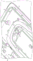
Fig. 29 shows a plan view of a sun visor according to an alternative embodiment of the present invention.
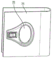
Fig. 30 shows a top view of a visor according to an alternative embodiment of the present invention.
Fig. 31 shows a top view of a visor according to an alternative embodiment of the present invention.
Fig. 32 shows a back view of a visor according to an alternative embodiment of the present invention.
Fig. 33 shows a cross-sectional view of a visor according to an alternative embodiment of the present invention.
Fig. 34 shows a plan view of a visor according to an alternative embodiment of the present invention.
Fig. 35 shows a top view of a visor according to an alternative embodiment of the present invention.
Fig. 36 shows a top view of a visor according to an alternative embodiment of the present invention.
Fig. 37 shows a cross-sectional view of a visor according to an alternative embodiment of the present invention.
Fig. 38 shows a cross-sectional view of a visor according to an alternative embodiment of the present invention.
Fig. 39 shows a bottom view of a visor according to an alternative embodiment of the present invention.
Fig. 40 shows a bottom view of a visor according to an alternative embodiment of the present invention.
Detailed Description
Referring to the drawings, a visor 30 according to an embodiment of the present invention is shown. In general, the present invention generally provides a clamshell-type vehicle visor 30 having a pivot rod 32 mounted to a carrier 34, wherein the pivot rod 32 and carrier 34 are slidingly captured during assembly with a single step of attaching the visor shell portions 36, 38 together. The carrier 34 thus rides in the visor body 42 itself, rather than a separate carrier, and is preferably retained between surfaces and/or features, such as the channel 40 integrally molded within the shell portions 36, 38. Similarly, the pivot rod 32 rides in the visor body 42 and no separate bracket, visor or the like is required to support the pivot rod 32. Related aspects of the invention include the method for manufacturing the visor 30 also described herein. Further, it should be noted that the sun visor 30 shown in the present application may be used in any known type of vehicle, such as, but not limited to, automotive vehicles, marine vehicles, aerospace vehicles, military vehicles, and any other known vehicle that requires blocking sunlight from entering an interior compartment of a vehicle. It should also be noted that all of the components of the sun visor 30 may generally be made of a plastic material that can be extruded, molded or formed by any known manufacturing process in accordance with the present invention. However, any other known metal, ceramic, plastic, composite, natural material, or any other known material may also be used for any of the parts or components of the sun visor 30 described herein. Further, it should be noted that the visor 30 of the present invention may be any known type of visor, such as a sliding visor, a non-sliding visor, a movable visor, or any other type of visor known in the vehicle industry.
In one embodiment shown in the drawings, the visor 30 includes first and second shell halves 36, 38 or shells, the first and second shell halves 36, 38 or shells being engageable to form an elongated visor body 42. Various molded features 48 may be included on each housing 36, 38 to facilitate engagement of the housings. For example, complementary structures may be formed on the respective visor housings 36, 38 to allow a snap fit therebetween. In one contemplated embodiment, the shells 36, 38 may be formed with integral or attached longitudinal peripheral edges 44, 46, respectively. Other embodiments are contemplated in which the housing is formed as a separate, unconnected member. Although a connected housing is preferred, the illustrated visor 30 may have an unconnected housing. The sun visor 30 may further include a pivot rod 32, the pivot rod 32 being disposed in one end of the sun visor body 42 and connected on an opposite end to a headliner or roof of the vehicle in which the sun visor 30 is disposed. The visor 30 is preferably formed such that the shells 36, 38 can be closed about the pivot rod 32 and thus capture the pivot rod 32 therebetween in a single assembly step. Further, the visor 30 may include a carrier 34, with the carrier 34 being slidingly captured by the closing or engagement of the shells 36, 38, slidingly securing the carrier between the shells 36, 38 without the need to mount an internal slide member, retainer or similar mechanism for mounting the pivot rod 32. All of the component parts of the sun visor 30 may be made of any known material and by known processes, such as, but not limited to, any type of plastic, metal, ceramic, composite, natural material, or any other known material, and the parts described herein are designed and manufactured by any type of molding, forming, chemical, and mechanical processes.
Generally, the housings 36, 38 are formed by injection molding a plastic material in a conventional manner. For example, the housings 36, 38 may be formed from molded polyethylene, or by some other suitable method and/or material. The first and second shells 36, 38 generally include retaining surfaces of any known shape, such as arcuate retaining surfaces, flat or angled retaining surfaces, all of which may be elongated or grooved surfaces extending parallel to the edges of the visor shell and defining a portion of a cylinder or wall. It should also be understood that the present invention may encompass designs having retaining surfaces that vary in size between the longer trough-shaped features shown in the figures and the narrower arcuate ribs. It should also be noted that a pair of surfaces in the form of arcs may be aligned near one end of the visor shells 36, 38 to allow the pivot rod 32 to be properly supported and able to rotate and slide relative to the visor body 42. The sun visor half shells 36, 38 may also have a channel formed near one edge thereof, wherein the channel may have a first bearing surface and a second bearing surface. These bearing surfaces may be disposed at any known angle relative to the centerline of the visor body 42. In one contemplated embodiment, the angled surfaces may be disposed on each side of a channel extending a predetermined distance along the longitudinal axis of the visor body 42, and the angled surfaces may be at any approximate angle relative to the centerline of the visor body 42. It should be noted that these inclined bearing surfaces may be disposed on each inner surface of the visor body 42. It should also be noted that the visor half shells 36, 38 may include other surfaces that receive and retain the various components of the sliding visor 36, such as, but not limited to, the pivot rod 32, D-rings, vanity 66 and cover material 52 disposed on the visor body 36 to complete the assembly thereof.
The shell halves 36, 38 forming the visor body 42 of the visor 30 according to the present invention may also include a plurality of hybrid snaps and ultrasonic weld joints. In one contemplated embodiment, a plurality of contoured snaps may be disposed around the front and side edges of the arc shells of the visor shells 36, 38. One shell may have a male portion of a contoured snap while the other shell may have a female portion that receives the male portion and retains the first shell to the second shell to provide a strong zero deflection interface between the two half shells 36, 38 to form a strong visor body 42. These clasps, arranged around the outer contour, can impart sufficient deflection to the front and side edges to allow the pleating process to occur as described below. The visor body 42 may also include at least one weld rod joint and at least one weld boss joint disposed at predetermined locations on the visor body 42. It should be noted that other contemplated methods and fasteners may be used to secure the two sun visor shell halves 36, 38 to one another, and it is also contemplated that the sun visor 30 is formed as a single body member rather than as two separate shell halves.
One of the housing halves may also include a predetermined shaped aperture or cavity 54 on its outer surface, which aperture or cavity 54 may be used to receive a vanity 66 and secure the vanity 66 to the visor body 42. The aperture or cavity 54 for receiving the compact 66 may include a plurality of locking surfaces or arms that may interact with a locking surface or flange of the frame 50 of the compact 66 to ensure that the compact 66 is secured to the outer surface of one of the shells of the visor body 42. These locking surfaces and fingers may take any known shape and are arranged so that both illuminated and non-illuminated sun visor vanities may be disposed therein. Other surfaces may also be molded into the visor half housings 36, 38 to allow placement of the electrical cord 58 to illuminate the visor vanity mirror 60, or to receive a universal garage door opener or other component directly into the visor body 42. The sun visor half shells 36, 38 according to the present invention may also include a plurality of teeth 62 disposed about the periphery of the front and side edges of each shell half 36, 38. These tines 62 generally have pyramidal or triangular shaped tines and may be directly aligned with each other from each half shell or offset from each other depending on design requirements and the pleating process to be used. This use of the teeth 62 to form the pleat edges and place the cover material 52 into engagement with the teeth through the pleat edge process may result in an aesthetically pleasing sun visor body 42 having a curled and clean outer cover material 52 disposed thereon. It should be noted that in one contemplated embodiment, the cover material 52 may be formed in the shape of a sock, wherein the sock is disposed over one end of the visor body 42 and then a pleating process is utilized to create clean front and side edges of the visor 30. However, any other known pleating process and covering material 52 that is not in the form of a sock may be used depending on the design requirements and the resulting shade panel 30.
According to the present invention, the visor 30 may further include a D-ring secured to the visor body 42 on a top edge thereof. The D-ring may be any known D-ring. The D-rings of the present invention may help, in part, retain the cover material 52 on the outer surfaces of the visor half shells 36, 38 formed into the visor body 42 in the taught clean manner. It should be noted that any shape may be used for the D-ring body and the D-ring pin associated therewith. The sun visor 30 may include a pivot rod 32, the pivot rod 32 being attached at one end to a bracket or connector that is secured to the headliner or roof of the vehicle. The bracket may have a connector secured thereto to connect the vehicle's electrical system to the bracket by way of electrical wires 58, the electrical wires 58 then passing through the pivot rod 32, the pivot rod 32 being generally hollow in accordance with the present invention. It should be noted, however, that a solid pivot rod 32 may also be used, so long as it is capable of passing electricity for allowing the vanity mirror 60 or map light 64 to be illuminated when necessary. The bracket may be secured to the roof of the vehicle via fasteners or any other known method. The bracket may include an aperture that will receive an end of the pivot rod 32 near the bend of the pivot rod 32, where the pivot rod 32 typically has an angle of 60 ° to 120 ° at the bend. The pivot rod 32 may be fixed and able to rotate within the aperture of the bracket and may also swing between the front windshield of the vehicle and the side windows of the vehicle to block the sun from any angle. The pivot rod 32 may have any known length and diameter depending on the design of the sun visor 30 and the vehicle in which the pivot rod 32 is disposed. The electrical cord 58 may be connected from the electrical system of the automobile and routed to the LED 64 for illuminating the visor mirror 60 in the vanity 66. It should be noted that the visor 30, the pivot rod 32 and the carrier may be made of any known material, such as, but not limited to, plastic, ceramic, composite, metal or natural materials, etc.
The visor pivot rod 32 is disposed within the carrier 34, and the carrier 34 is disposed within the visor body 42. If the shield 36 is a sliding shield, the carrier 34 can move in a sliding manner. If the visor 30 is not a sliding visor, the carrier 34 is fixed relative to the visor body 42. In a sliding visor, the carrier 34 may slide within the channel 68 of the visor body 42 to allow the visor 30 to extend out toward the end of the visor rod 32 that is fixed within the visor body 42. Any known carrier 34 may be used to secure the pivot rod 32 to the visor body 42, such as, but not limited to, a floating carrier, a fixed carrier, or any other known carrier associated with the visor rod 32 and visor body 42.
The visor 30 may also include a wiring system that passes the electrical wiring 58 from the carrier through the pivot rod 32 to the LED 64 vanity light for illuminating the vanity mirror 60 therein. Any known wiring system may be used to pass the wires 58 through the visor body 42 to the circuit board 70 for controlling and operating the LEDs 64 thereon. It should also be noted that it is also contemplated that an onboard power source may be used to illuminate the LEDs 64 of the vanity 66 of the visor 30.
The visor 30 may also include a vanity 66. The vanity 66 generally includes a vanity door 72, door springs, vanity springs, and vanity mirror 60, as well as optional lights disposed on the vanity 66. If the compact 66 is illuminated, the compact 66 may also include at least one lens 74 to scatter light in a predetermined manner. In another contemplated embodiment, the vanity frame 50 may include two lenses 74, one disposed on each side of the vanity 66 to illuminate the mirror 60. The vanity frame 50 may generally include at least one connecting flange, but in the illustrated embodiment, two connecting flanges are disposed near or at a bottom surface of the vanity frame 50. The opposite end of the vanity frame 50 may have at least one locking shoulder or surface disposed therein that may interact with a locking tab disposed on a surface of one of the sun visor housing halves 36, 38. This may allow the vanity frame 50 and vanity 66 to be secured to the visor body 42 without fasteners (e.g., screws, etc.). It should be noted, however, that another embodiment may use fasteners and screws to attach the vanity frame 50 to the visor body 42. One contemplated embodiment may create a snap in cosmetic case 66. Generally, the vanity frame 50 and door 72 may have a rectangular or oval shape, but any other shape of vanity 66 may be used depending on the design requirements of the visor 30. The compact 66 and frame 50 may also include a flexure hook disposed at one end thereof and a leaf spring disposed on an opposite edge of an aperture defined in the middle of the compact frame 50. Adjacent to the leaf spring may be one or two locking tabs. This combination of flexing hooks, leaf springs, and locking tabs, as well as lens tabs for securing the lens 74 to the vanity frame 50, may be used to secure the mirror 60 in the flexible interface without adhesive. In operation, the mirror 60 is placed under the flex hook and then snapped under the lock tab and against the leaf spring to secure the mirror 60 to the vanity frame 50 without the use of adhesives. However, it is also contemplated that the mirror 60 may be secured to the vanity frame 50 with an adhesive or any other method. The lens tabs, which are typically disposed on either side of the vanity frame 50, may properly position the vanity mirror 60 in the left-right direction relative to the vanity frame 50. Thus, vanity mirror 60, which may be of any shape, size, or thickness, may be held in place on vanity frame 50 without adhesive, whereas in the prior art, vanity mirror 60 is typically held to frame 50 using adhesive. It should be noted that any number of leaf springs, locking tabs, and flexing hooks may be used to retain the vanity mirror 60 in accordance with the present invention. The vanity frame 50 may be inserted into the visor body 42 by securing first and second flanges disposed near one end of the vanity frame 50 under an in-car hook molded into the outer surface of one of the core visor body half shells 36, 38. These flanges may be disposed under the in-car hooks and then the opposite end of the vanity frame 50 may be snapped into place by a downward force so that the locking shoulders or surfaces of the vanity frame 50 may interact with locking tabs or snaps molded into the outer surfaces of the sun visor half shells 36, 38 on the sun visor half shells 36, 38 and molded into the sun visor half shells 36, 38. In systems where fasteners, such as screws, are not required to secure the vanity system to visor body 42, this may utilize snaps to secure vanity 66 to visor body 42. It should be noted that the vanity 66 of the present invention may include fasteners and screws to secure the vanity 66 to the visor body 42.
It should be noted that the visor half shells 36, 38 that hold and support the vanity 66 may also include a light socket 80 secured thereto. In one contemplated embodiment, the light socket 80 is molded into one of the shells 36, 38, such as the second shell 38 of the visor body 42. The socket 80 may include a recess 82 therein, the recess 82 securing the circuit board 70 therein to maintain the circuit board 70 in a predetermined fixed position relative to the second housing 38 and the cosmetic case 66. The dimples 82 may be formed or molded into a predetermined interior surface of the second housing 38. The lamp socket 80 in this embodiment has a recess 82 defined in part by first and second guide members 84, wherein the first and second guide members 84 extend from the inner surface of the second housing 38 and are parallel to each other. Each of the first and second guide members 84 may have an inwardly extending flange 86 extending from a top end thereof. The flange 86 may engage a top surface of the circuit board 70 to help secure the circuit board 70 relative to the vanity 66. The first and second guide members 84 may generally have any known predetermined shape, but may have a generally L-shaped shape when viewed from the front. The L-shape may define a seat on each guide member 84 on which the circuit board 70 may rest or rest. The seat portion of the guide member 84 and the bottom surface of the inwardly extending flange 86 of the lamp socket 80 may have a predetermined distance therebetween. The predetermined distance may be generally equal to or greater than the thickness of the circuit board 70 disposed therein. The lamp socket 80 may further include a stopper wall 88 disposed at a rear end thereof. The stopper wall 88 may extend away from the inner surface of the second shell 38 of the visor body 42 in a predetermined direction. During operation, the circuit board 70 may slide within the front side of the recess 82 of the socket 80 until one end of the circuit board 70 engages the stop wall 88 of the socket 80. The socket 80 may also include a locking arm 90, the locking arm 90 being disposed generally at the centerline of the recess 82. The locking arm 90 may engage with a predetermined portion of the circuit board 70 and fix the circuit board 70 within the lamp socket 80. The locking arm 90 may have a generally rectangular shape with a locking shoulder 92 disposed on an end of the locking arm 90. One end of the locking arm 90 may be molded directly into the surface of one of the half shells 36, 38 of the visor body 42. The other end may be movable or flexible to allow the locking arm 90 to pivot about a first end that is fixed and molded into the visor body half shell. This may allow movement of the locking shoulder 92 and locking arm 90 to engage predetermined portions of the circuit board 70. The locking arm 90 may have a predetermined spring rate that may allow the locking arm 90 to securely hold the circuit board 70 at a predetermined position relative to the compact 66.
The lamp socket 80 may further include a gap or recess 94 formed between two predetermined surfaces to form a wiring channel of the circuit board 70. The electrical wire 58 may be connected to one end of the circuit board 70 and the other end to the vehicle's electrical system, wherein the electrical wire 58 may extend through a predetermined area of the visor body 42 and through the pivot rod 32 into the vehicle's electrical system. The circuit board 70 may have a generally rectangular shape with a predetermined length, width and thickness. It should be noted that the circuit board 70 may have any known shape, but in the illustrated embodiment is rectangular. Disposed on the top surface of the circuit board 70 is an LED 64. It should be noted that the LEDs 64 may be of any type, color, and any known shape. The LEDs 64 as shown are generally square LEDs 64. The electrical components 96 may be disposed on the circuit board 70 and form the necessary circuitry for illuminating the LEDs 64 and passing such illumination light 70 to the lens 74 and mirror 60 of the vanity 66. The electronic components 96 may be, but are not limited to, diodes, resistors, capacitors, integrated circuits, or any other known electrical components necessary to operate the LEDs 64. It should be noted that the LED 64 in the illustrated embodiment is secured within the socket 80 such that the circuit board 70 is parallel to the inner surface of the visor body 42. This effectively holds the circuit board 70 in a horizontal position relative to the visor body 42. The use of this embodiment of the light socket 80 may provide a direct bulb replacement for an LED illuminated visor. This may allow the circuit board 70 and LED 64 to be positioned in substantially the same location or area as the prior art light bulb and socket used in prior art visor designs. Generally, no changes to the cosmetic case assembly are required other than molding the light socket 80 therein. It should be noted that the circuit board 70 typically has a plurality of electronic components 96 disposed on a bottom surface thereof and on opposite sides of the LEDs 64, which plurality of electronic components 96 may be disposed on a top surface of the circuit board 70. The circuit board 70 may further include a locking member 98 extending from the bottom surface, wherein the locking member 98 may interact and inter-engage with the locking shoulder 92 of the locking arm 90 of the visor body 42. It should be noted that the light holder 80 and the circuit board 70 may be disposed on each side of the cosmetic case 66. However, it is also conceivable to arrange the LED 64 only on one side of the cosmetic case 66, and even to use the LED 64 only on one side of the cosmetic case 66 and to transfer light from the LED 64 to both ends or both sides of the mirror 60 of the cosmetic case 66 via a light guide.
Another embodiment of the sun visor 30 may include the light base 100, the light base 100 being a separate component molded or formed separately from the visor body half shells 36, 38. In this embodiment, the lamp socket 100 generally has a rectangular body including first and second guide rails 102 parallel to each other on a bottom surface thereof. Rail 102 has a generally circular shape and extends from bottom corner edges on each side thereof. The parallel guide 102 may have a predetermined diameter that may mate with and interengage a predetermined channel molded in one of the shells 36, 38 of the sun visor 30. The lamp socket 100 may further include a first arm and a second arm 104, one of which extends from each side thereof near the middle of the lamp socket 100. The arms 104 may generally have any known shape, such as, but not limited to, a semi-circular or semi-silo shape when viewed from above. The arm 104 may extend a predetermined distance from the side of the lamp socket 100. The arm 104 may have an inclined surface on its top side. The lamp socket 100 may also include locking tabs 106 extending from a bottom surface thereof, wherein the locking tabs 106 interact and engage locking slots 108 disposed and molded within the housing 38. The locking tabs 106 may generally extend between the first and second parallel rails 102 and from the bottom surface of the lamp socket 100 such that the tabs 106 generally have an arcuate shape extending from the bottom surface of the lamp socket 100 with the locking tabs 106 extending a predetermined distance beyond the surface of the rails 102. In one embodiment, the locking tabs 106 are generally aligned along a midpoint of the first and second arms 104 extending from one side of the lamp socket 100. A slot 110 is disposed on one end of the lamp socket 100. The slot 110 is formed such that the circuit board 70 is placed within the slot 110 and fixed in a predetermined position relative to the second housing 38. The slot 110 is defined in part by first and second legs 112 extending from the socket 100. The first and second legs 112 may each have a groove having a generally square shape disposed at a midpoint thereof. Each of the recesses disposed in the first and second legs 112 may be used to retain one edge of the circuit board 70 disposed therein. A predetermined distance is disposed between the first and second grooves such that the predetermined distance is substantially equal to the width of the circuit board 70. This may allow the circuit board 70 to slide within the slot 110 arranged on the front end of the lamp holder 100 and secure the circuit board 70 to the lamp holder 100 via the locking snap members 114 arranged on the surface of the lamp holder 100. The locking snap members 114 may be arranged generally near or on a surface near the midpoint of the lamp holder 100. Each arm 112 of the lamp socket 100 may have a reinforcing rib 116 extending from a bottom surface of the arm 112 to a surface of the lamp socket 100. The stiffening ribs 116 may have a generally triangular shape when viewed from the side. The snap lock members 114 may be disposed between the ribs 116 adjacent to a cavity of predetermined shape disposed within an end of the lamp socket 100. The predetermined cavity may generally have any known shape, but in the current embodiment generally has a rectangular or square shape. This may allow the locking members 98 extending from the bottom surface of the circuit board 70 to interengage with the snap locking members 114 and hold the circuit board 70 in place within the lamp socket 100 of the present invention. The snap lock members 114 may have any known shape, and in one embodiment, the snap lock members 114 have a generally triangular shape and extend a predetermined distance from the ends of the lamp socket 100 and into the cavity of the lock member 98 that holds the circuit board 70. This may allow interaction and engagement of the snap lock members 114 with the lock members of the circuit board 70. It should be noted that the snap locking member 115 is only one contemplated embodiment for securing the circuit board 70 within the lamp socket 100, and any other known locking feature may be used to secure the circuit board 70 within the lamp socket 100. The light base 100 of this embodiment may interact with features molded into the interior surface of one of the sun visor body 42 half shells 36, 35. The second housing 38 may have first, second, third and fourth locking surfaces 118 molded therein. The locking surface 118 is generally defined as a slightly inclined surface molded into one of the sun visor half shells 36, 38. The surfaces 118 may intersect one another to form a gap of a predetermined size. The gap of predetermined size may be generally the same as or slightly larger than the thickness of one arm 104 of the lamp socket 100. This may allow the lamp holder 100 to slide through these gaps such that the arms 104 interact with the first and second locking surfaces 118, wherein the first locking surface 118 may generate a force that may push the first locking surface 118 down onto the arms 104 of the lamp holder 100, while the second locking surface 118 may actually push onto the arms 104 of the locking surface 118 with an upward force, which may actually wedge the lamp holder 100 into the half shells 38 via the arms 104 extending from each side thereof. Thus, first and second locking surfaces 118 may be disposed on each side of the light base 100 and formed within the visor half shell 38. The sun visor half shell 38 may also have molded therein third and fourth locking surfaces 118. The third and fourth locking surfaces 118 may generally be defined by edges or surfaces extending from predetermined flanges molded into the sun visor half shell 38. The third locking surface may interengage with one of the rails 102 and the fourth locking surface 118 may interengage with another one of the rails 102 of the lamp socket 100. Thus, the third and fourth locking surfaces 118 may be disposed proximate to each other such that the gap therebetween may be substantially equal to or greater than the diameter of one of the rails 102. It should also be noted that the third and fourth locking surfaces 118 may be angled relative to the rails 102 such that each rail 102 may be wedged between the third and fourth locking surfaces 118 molded into one of the visor half shells 38. It should be noted that all of the locking surfaces 118 or features described herein are typically formed by flanges or channels molded directly into the sun visor half shell 38. In operation, the light socket 100 described in this embodiment may be slid and locked into place within the visor half shell 38. The locking tabs 106 may interengage with locking slots 108, the locking slots 108 being formed generally at the midpoint of the lamp socket 100 and molded into the surface of the second housing 38. This may allow the light base 100 to interengage with the sun visor half shell 38 at four points and lock via one point, thereby securing the light base 100 in a predetermined position relative to the sun visor half shell 38 and vanity 66. After the light socket 100 is inserted and secured into the visor half shell 38, the electrical wires 58 may be connected between the surface of the circuit board 70 and the vehicle's electrical system. This may allow for a direct replacement of the light bulb system of the prior art sun visor.
Yet another embodiment of the lamp socket 120 may generally have the same body, rails 102, and arms 104 as the lamp socket 100 described above. This embodiment of the lamp holder 120 may further include a first slot 122 disposed along a lateral portion of the top surface of the lamp holder 120. The slot 122 may extend across the entire width of the lamp socket 120. The slot 122 may be used to secure and retain one longitudinal edge of the circuit board 70. Directly adjacent to the slot 122 on the top surface of the lamp holder 120 may be a locking member 124 extending from the top surface thereof. The locking member 124 may be directly adjacent the slot 122 and have a generally U-shape when viewed from the front thereof. The locking member 124 may have first and second legs 126 extending from the top surface of the lamp socket 120 and a cross member 128 extending between the two legs 126. In general, the front of the locking member 124 may share the same plane with one of the inwardly extending surface walls of the slot 122. Each leg 126 may have a generally triangular shape when viewed from the side, although any other shape may be used. The locking member 124 may have a configuration such that: that is, a generally rectangular aperture may be formed through the center of the locking member 124. Electrical components or other locking members extending from a surface of the circuit board 70 may be used to interact with at least one surface of the locking member 124 of the lamp socket 120. This may secure and hold the circuit board 70 in a predetermined position relative to the lamp socket 120. The wires 38 may be connected to the circuit board 70 on either side or end of the circuit board 70. The top side of the circuit board 70 may have LEDs 64 affixed thereto and in electrical communication with the electronics of the circuit board 70 and the vehicle's electrical system. The lamp socket 120 may further include a recess 130, the recess 130 being disposed adjacent to the slot 122 on an opposite side of the locking member 124. The recess 130 may extend into the lamp socket 120 by a predetermined distance. The dimple 130 has a generally rectangular shape when viewed from above. The slots 122 of the alternate embodiment of the light socket 120 may generally hold the circuit board 70 in an upright position relative to the visor body half shell 38. This may allow the LED 64 to be held in place in the visor 30 in a vertical manner, allowing the light guide 132 to be used in conjunction with the vanity 66.
The light guide 132 may generally be any known shape, but in the illustrated embodiment, the light guide 132 generally has a modified pyramid shape with a generally circular bottom portion and a parallelogram-type top portion. It should be noted that any known shape may be used for the light guide 132 of the present invention. One end of the light guide 132 having the smaller dimension may generally have a notch or cut-out 134 disposed therein. The cutout 134 may be used to align with the LED 64 disposed on the circuit board 70 of the present invention. The light guide 132 having any known shape may be used in any known visor 30. A notch or cut-out 134 is disposed on one edge of the light guide 132 and may have any known shape, but is typically a square type cut-out shape that may resemble the square shape of the LEDs 64 used herein. The LEDs 64 may direct their light into the edge or end of the light guide 132 in a head-on manner, thus allowing the light to be uniformly scattered throughout the light guide 132. The use of light guide 132 may provide a warmer and more uniform appearance of light passing through lens 74 of vanity 66. The light distribution through the light guide 132 may ensure that there are no hot spots when compared to the light distribution from a common light bulb. It should be noted that the LED 64 may contact or engage the light guide 132, but need not be, and the vanity 66 may have one or more lights disposed therein. It is also contemplated to use light guides 132 extending from both sides of the vanity 66 so that light may be emitted via one LED 64 to both sides of the mirror 60 within the vanity 66. However, it is also conceivable to use two separate light guides 132, one arranged at each end of the vanity 66, and a lamp socket 120 arranged at each end thereof, to form the illumination light of the sun visor 30 according to the invention. It should be noted that the light guide 132 has a predetermined thickness and is made of any known predetermined material capable of producing the light distribution required by the present invention. It should be appreciated that any known or unknown material may be used for the light guides and light guide systems arranged herein. It should also be noted that one or more LEDs 64 may be directly affixed or attached to the light guide 132 at predetermined locations on the light guide 132, such as, but not limited to, the notches 134 and the like. The electronics required to operate the LED 64 directly attached to the light guide 132 may be disposed between the LED 64 and a power source for the visor or vehicle. In general, the light guide 132 of the present invention may be disposed within the visor vanity frame 50 with the lens 74 disposed on a top surface thereof to protect the light guide surface. The lens 74 may be of any known type or design. In one contemplated embodiment, the recess 134 of the light guide 132 may be approximately 4 millimeters wide, but any other shape, width, or recess may be used for the input light region of the light guide 132. The compact frame 50 of the present invention may include a predetermined shaped aperture therein that generally resembles the profile of the light guide 132. The light guide 132 may then be retained within the vanity frame 50 by press fitting using crush ribs 136 at strategic locations such as at each corner end of the light guide 132. It should be noted, however, that it is also contemplated to have the light guide 132 slide into place or held in place by a snap or rivet operation to ensure that the light guide 132 remains fixed relative to the vanity frame 50 and the light holder 120, the light holder 120 holding and securing the LED 64 relative to the light guide 132. Thus, any known retention method, such as press-fitting, snapping, or riveting, may be used to retain the light guide 132 in place on one or both ends of the vanity frame 50, and then the vanity frame 50 may have a lens 74 disposed on top of the light guide adjacent the mirror 60 to provide illumination of the mirror 60 to the user via the LED lamp 64 and the light guide 132. It should also be noted that predetermined openings or through holes 142 in the ribs and other components of the sun visor half shell 38 may be disposed therethrough in order to pass the electrical wiring 58 from the vehicle's electrical system to the circuit board 70 of the light holder 120, with the circuit board 70 being held in an upright position.
In the LED sun visor compact of the present invention, it is also conceivable that: instead of using a lens 74 over the light guide 132 or the direct replacement LED 64, either of the light guide 132 or the direct replacement LED 64 may be covered by extending the mirror 60 to the end of the visor vanity frame 50 and removing any adhesive on the bottom of the mirror 60. This may allow light to be emitted directly through the mirror 60 and may not require the use of a lens 74 to scatter the LED light in a predetermined manner. Further, it is also contemplated that the grill 140 may be molded into the vanity frame 50 to protect the light guide 132 or the LED 64 and to scatter light from the light guide 132 or the LED 64 in a predetermined manner. It is contemplated that the grates 140 may have any known shape, such as a honeycomb design, or an arc with a support arm design as shown. Any of these molded grids 140 or extensions of the mirror 60 while removing tape on the bottom of the mirror can be used in conjunction with the LED system of the present invention. It should be noted that it is also contemplated that, in accordance with the present invention, the map lamp 138, which may be disposed in the first or second housing 36, 38 of the visor body 42, may use the light emitting diodes 64 and the light sockets 80 associated therewith to provide the map lamp 138 for use by a user of the vehicle, wherein the map lamp 138 may be a separate lighting system from the vanity mirror lighting system described herein.
Fig. 29 to 33 show an alternative embodiment of an LED visor 230 according to the present invention. Like numbers refer to like elements throughout. Alternative embodiments of the visor 230 may include a visor half shell 236, which half shell 236 may include other surfaces that receive and retain components of the sliding visor 230, such as, but not limited to, pivot rods, D-rings, vanity boxes, and cover materials that are disposed on the visor body 242 to complete the assembly thereof. The manner in which all of these components described herein are connected to one another, and the components used and formed in each of these components, are substantially the same as those described above. The sun visor body 242 comprised of the first half shell 236 and the second half shell 238 may allow the frameless vanity 266 to be secured to the sun visor body 242, thereby allowing the vanity 266 to be used by the vehicle occupants. In one contemplated embodiment, one of the half shells (in this case, the first half shell 236) includes a compact pocket 235 disposed in a predetermined top surface of the first half shell 236. In one contemplated embodiment, the vanity pocket recess 235 is disposed near one end of the visor half shell 236. However, the vanity pockets 235 may be disposed anywhere along the sun visor half shell surface. Compact pit 235 generally has a rectangular shape, but it should be noted that any other shape may be used to form compact pit 235, including but not limited to oval, circular, square, triangular, or any other shape. The vanity pockets 235 may be recessed into the top surface of the visor first half shell 236 by a predetermined distance. This distance may allow all of the components necessary to operate vanity 266 to be disposed therein and create an aesthetically pleasing surface for a user of sun visor 230 within the vehicle. The compact pit 235 may include a plurality of channels formed therein. In one contemplated embodiment, the compact pocket 235 may include first and second circuit board channels 249, in which a circuit board 270 may be disposed and secured for use with the compact 266. The compact pocket 235 may also include a wire harness channel 237 disposed along or near a top end of the compact pocket 235. In one contemplated embodiment, the wire harness passage 237 and the circuit board passage 249 have a generally rectangular shape when viewed from above. It should be noted that any other shape of channel may be used for the channels described herein. The wire harness passage 237 and the first and second circuit board passages 249 are connected to each other, and generally form a C-shape when viewed from above. It should also be noted that each circuit board channel 249 may include a projecting member or finger 251 that extends a predetermined distance from an inner surface of each circuit board channel 249. These fingers 251 may be used to align and secure the circuit board 270 in a predetermined position relative to the channel 249. Directly adjacent to the first and second circuit board channels 249 may be a first light guide channel and a second light guide channel 253. Light guide channel 253 may generally resemble the profile of light guide 232 that may be used in a visor 230 according to the present invention. In one contemplated embodiment, light guide channel 253 may have a generally oval portion shape or a semi-circular shape, in accordance with the design and outer edge shape of light guide 253 of the present invention. It should be noted that in one contemplated embodiment, light guide channel 253 extends a predetermined distance from the bottom of compact pocket 235, but does not extend to circuit board channel 249 and harness channel 237. However, it is also contemplated that all channels extend the same distance from the bottom of the compact pocket 235, such that the light guide channel 253, circuit board channel 249, and wiring harness channel 237 all extend the same distance from the bottom of the compact pocket 235. In one contemplated embodiment, disposed between each light guide channel 238 and circuit board channel 249 are triangular shaped first and second wedge members 255. These wedge members 255 may allow for proper positioning of the circuit board 270 relative to the light guides 232 such that the wedges may resemble one surface of the light guides 232, thereby allowing the light guides 232 to be securely disposed within the light guide channels 253 without any movement relative to the visor body 242. It should also be noted that the vanity pockets 235 may include a predetermined sloped surface that extends at any known angle downwardly from the top surface of the first sun visor body half shell 236 to any known shape of vanity pocket 235.
Fig. 34 to 40 show a further alternative embodiment of a sun visor 330 according to the present invention. Like numbers refer to like elements throughout. This alternative embodiment includes a first half shell 336 and a second half shell that are shaped together to form a visor body 342. The visor half shell may include many other surfaces that receive and retain various components of the visor 330 such as, but not limited to, pivot rods, D-rings, vanity 366 and cover materials such as those described above disposed on the visor body 312 to complete assembly thereof. In this alternative embodiment, visor 320 may have a first half shell 336 with a vanity pocket 335 disposed in first half shell 336. Vanity pocket 335 may generally have the overall appearance of vanity frame 351, which is used to connect vanity 366 to visor body 342. In the illustrated embodiment, it is generally rectangular in shape with rounded edges. However, any other shape may be used for compact 366 and compact pocket 355 described herein, such as rectangular, square, circular, oval, triangular, or any other known shape. The makeup pocket 335 may extend a predetermined distance from the top surface of the first half housing 336. The compact pocket 335 may also include first and second circuit board channels 353 and first and second light guide channels 363 disposed therein. A first channel 353 and a second channel 363 are generally disposed near each outer end of the compact pocket 325. In the embodiment shown, the light-guide channel 363 does not extend as far from the top surface of the first half housing 336 as the circuit board channel 353 does. As described above, the circuit board path 353 has a generally rectangular shape when viewed from above, and the light guide path 363 has a generally semicircular shape or D-shape when viewed from above. The light guide 332 may be placed within the light guide channel 363 such that a bottom surface of the light guide 332 interacts and engages a top surface of the light guide channel 363, and the bottom surface may be aligned with a circuit board 370 placed and secured within the circuit board channel 353 such that an LED light connected to the circuit board 370 may illuminate the light guide 332 as described above. The periphery of the light guide 332 may be similar to the periphery of the light guide channel 363 such that the light guide 332 does not move relative to the visor body 342. A design substantially identical to that of the circuit board 370 described above may also be used in this embodiment so that the circuit board 370 does not move within the circuit board channel 353, thereby ensuring proper alignment of the LEDs with the light guide 332. In the illustrated embodiment of this alternative embodiment, no harness channels are used. However, it may also be incorporated into the present design according to design requirements. Thus, the circuit board channels 353 are parallel to each other, and each channel is disposed near one end of the compact pocket 335 or at a predetermined distance from the actual end of the compact pocket 335. The compact pocket 335 may also include a flange or shoulder 357 disposed around the entire inner circumferential periphery thereof. Mirror flange 365 is disposed adjacent flange 357. The mirror ledge 365 may generally resemble the shape of the mirror 360 and may allow the outer edge of the mirror 360 to sit on the mirror ledge 365 within the vanity pocket 335. The flange 357 may be parallel to the top surface of the first half housing 336. The flange 357 may include a plurality of locking slots 367, the locking slots 367 being arranged at predetermined intervals around the entire peripheral circumference of the cosmetic case pocket flange 357. In general, these locking slots 367 may be rectangular when viewed from above, but any other shape of locking slot may be used, and any number of locking slots may also be arranged around the compact pocket flange 357 in any known manner.
The visor 330 also includes a vanity frame 351. The cosmetic case frame 351 may have a generally rectangular shape with curved ends. The shape may resemble the shape of the compact pocket 335 and thus may be any known shape. The vanity frame 351 may also include at least one slot 369, but in the embodiment shown there are two slots 369 through which the door hinge may be attached to the frame. Accordingly, the top portion of the cosmetic case frame 351 may be wider than both side portions and the bottom portion of the cosmetic case frame 351. Extending from the bottom surface of the vanity frame 351 may be a plurality of mirror frame snap members or locking members 355. The mirror frame lock catch member 355 may be generally rectangular with a wedge or triangular shaped end thereon. The triangular end may form a locking shoulder for the mirror frame locking catch 355. The locking shoulder may interengage with a locking surface disposed through a locking slot 367 of the case pocket flange 357. Thus, the locking shoulder may interengage with the bottom surface of the compact pocket flange 357 to secure the compact frame 351 to the visor body 342. It should be noted that the mirror frame locking snaps 355 can be arranged in any known pattern around the periphery of the vanity frame 351. As described above, the mirror frame locking catch 355 can align with and engage a locking slot 367 disposed through the compact pocket flange 357. The mirror frame locking catch 355 can have any known width and length. In the illustrated embodiment, a total of twelve vanity mirror frame locking snaps 355 are disposed at predetermined locations around the vanity frame 351. Thus, the number of locking slots 367 is the same as the number of locking snaps 355, and the locking slots 367 are disposed through the first half shell 336. Disposed from the wider top portion of the cosmetic case frame 351 may be first and second door connector members 361. The door connector member 361 is generally the same as those described above for the other embodiments. Thus, the door connector member 361 may have a generally circular channel capable of receiving the pin of the hinge of the door 372, such that the door 372 may be pivotally connected to the door connector member 361 and thus to the visor body 342. It should be noted that the first half housing 336 may have first and second apertures that have a generally rectangular shape when viewed from above, which may allow the first and second door connector members 361 to extend therethrough. This may allow the vanity frame 351 to snap into and connect and secure to the visor body 342. It should be noted that such a snap-on system may allow for easy installation of vanity 366 into the visor 330 of a motor vehicle. In the illustrated embodiment, the electrical connector 359 is disposed adjacent one of the door connector members 361 and secured to the inner surface of the first sun visor half shell 359 by any known connection method. The electrical connector 359 is then connected to the vehicle's electrical system and to the circuit board 378 so that power is provided to the LEDs for providing the light emitting and illuminating mirror 360 for the sun visor 330. It should be noted that mirror 360 is generally the same as the mirrors described above, as mirror 360 may have two transparent ends at each end, one transparent end at one end, or no transparent ends, depending on the design requirements of compact 366. It should also be noted that the vanity frame 351 may also include a mirror flange 371 disposed around an inner perimeter of the vanity frame 351. The mirror flange 371 may have a generally oval shape or a rectangular shape with curved ends to mimic the inner diameter of the inner periphery of the vanity frame 351. The mirror flange 371 may be generally parallel to the top surface of the first half housing 336. The mirror flange 371 may be used, in part, to secure the mirror 360 within the visor body 342. In one contemplated embodiment, the mirror 360 may be held in place and mechanically secured within the visor body 342 by a mirror flange 371 of the vanity frame 351 engaging the vanity pocket 335 of the first half shell 336 and securing the mirror 360 within the vanity pocket 335. Thus, the bottom of the mirror 360 may be disposed in contact with the surface of the vanity pocket 335, while the mirror 360 is also in contact with the mirror flange 371, which may be disposed along the inner perimeter of the vanity frame 351. Thus, when the vanity frame 351 is snapped into the visor first half shell 336, it may in turn secure the mirror 360 in place relative to the light guide 332, the circuit board 370, the door 372 and the visor body 342. It should be noted that all of the components, except for the door spring 339, may be made of plastic material, however, any other metal, ceramic, composite, or natural material may be used for any of these components. The same applies to door springs, which may be made of any known metal, plastic, ceramic, composite or natural material. It should also be noted that the door 372 and door hinge system are generally the same as those described above for the other alternative embodiments. In one embodiment, the vanity frame locking catch 355 may generally have four locking catches 355 disposed at predetermined positions along the first and second long edges, and two locking catches 355 disposed at predetermined positions generally on the shorter length edge of the vanity frame 351. However, any other number of locking snap members 355 may be used in any type of arrangement or positioning.
Thus, in operation, two alternative embodiments of the sun visor may be more easily manufactured and have the compact mounted therein via the snap in locking systems deployed in the frameless compact and locked compact frame embodiments. This easy installation of the vanity within the visor body may reduce manufacturing time and reduce the overall cost to the manufacturer, while also allowing for reduced material costs, since the transparent end of the mirror may allow for the removal of the lens and associated hardware for connecting the lens to be disposed over the light guide or LED of the present invention.
The invention has been described in an illustrative manner. It is to be understood that the terminology, which has been used, is intended to be in the nature of words of description rather than of limitation.
Many modifications and variations of the present invention are possible in light of the above teachings. Therefore, within the scope of the appended claims, the invention may be practiced other than as specifically described.
Claims (20)
1. A visor for use in a vehicle, said visor comprising:
a pivot rod;
a first shell and a second shell engageable to form a visor body, wherein the first shell has a vanity pocket disposed within the first shell, the vanity pocket having a first flange, the vanity pocket having a second flange disposed adjacent the first flange;
a cosmetic case fixed to the first housing;
a mirror having at least one transparent end, the mirror being secured within the vanity by a vanity frame, a bottom surface of the mirror contacting the second flange, a top surface of the mirror engaging the inwardly extending flange of the vanity frame;
a circuit board disposed within the first channel of the vanity pocket;
a light guide disposed adjacent to the circuit board, the light guide positioned below the transparent end of the mirror; and
a light emitting diode secured to a surface of the circuit board.
2. The visor of claim 1 further comprising a door pivotally connected to said vanity frame.
3. The visor of claim 1 further comprising a plurality of vanity frame snaps extending from a bottom surface of said vanity frame, said bottom surface of said vanity frame engaging said first flange.
4. The visor of claim 3 wherein said first shell having a plurality of locking slots, said plurality of locking slots being arranged around a periphery of said vanity pocket.
5. The visor of claim 4 wherein said locking slot interacts and engages said vanity frame snap to secure said vanity to said visor body.
6. The visor of claim 1 wherein said inwardly extending flange is disposed from an inner periphery of said vanity frame.
7. The visor of claim 6 wherein said inwardly extending flange secures said mirror within said vanity, said inwardly extending flange engaging said mirror around an entire outer edge of said mirror.
8. The visor of claim 1 wherein said light guide is disposed within a second channel of a vanity pocket recess of said first shell.
9. The visor of claim 1 wherein said mirror having said transparent ends at both ends of said mirror.
10. The visor of claim 1 wherein said light emitting diode illuminates said light guide, said light guide illuminated from under said mirror.
11. The visor of claim 4 wherein said plurality of locking slots are disposed in said first flange.
12. A visor for use in a vehicle, said visor comprising:
a pivot rod;
a first shell and a second shell engageable to form a visor body;
a cosmetic case pocket formed within the first housing;
a mirror disposed within the vanity pocket;
a door mounting panel fixed to and in contact with the first housing at a top portion of the makeup pan, the door mounting panel having a door connector member disposed from a bottom surface of the door mounting panel;
a door pivotally connected to the door mounting panel;
a circuit board disposed within the first channel of the vanity pocket;
a light guide disposed adjacent to the circuit board, the light guide disposed within the second channel of the vanity pocket, the light guide positioned below an end of the mirror; and
a light emitting diode secured to a surface of the circuit board.
13. The visor of claim 12 further comprising a wire harness channel disposed within said vanity pocket, said door mounting panel having a general S-shape when viewed in cross-section.
14. The visor of claim 13 further comprising at least one wire electrically connected to said circuit board, said wire being disposed within said wire harness channel.
15. The visor of claim 12 wherein said door mount panel having a plurality of locking snaps extending from a surface of said door mount panel, said vanity pocket having a positioning member disposed between said first channel and said second channel.
16. The visor of claim 15 wherein said first shell having a plurality of locking slots through a surface of said first shell.
17. The visor of claim 16 wherein said locking slot and said locking snap interengage to secure said door mounting panel to said first shell.
18. The visor of claim 12 further comprising a door spring disposed between a spring pocket of said door mounting panel and a door hinge of said door, said door mounting panel having a generally wing shape.
19. The visor of claim 12 wherein said mirror having transparent ends at both ends of said mirror.
20. The visor of claim 12 wherein said mirror is secured to said vanity pocket recess by an adhesive, tape or a hook and loop connector.
Applications Claiming Priority (3)
| Application Number | Priority Date | Filing Date | Title |
|---|---|---|---|
| US14/996,530 | 2016-01-15 | ||
| US14/996,530 US10737559B2 (en) | 2014-12-16 | 2016-01-15 | Visor |
| PCT/US2017/012692 WO2017123494A1 (en) | 2016-01-15 | 2017-01-09 | Visor |
Publications (2)
| Publication Number | Publication Date |
|---|---|
| CN108698491A CN108698491A (en) | 2018-10-23 |
| CN108698491B true CN108698491B (en) | 2021-10-19 |
Family
ID=59311454
Family Applications (1)
| Application Number | Title | Priority Date | Filing Date |
|---|---|---|---|
| CN201780006782.1A Active CN108698491B (en) | 2016-01-15 | 2017-01-09 | Sun shield |
Country Status (7)
| Country | Link |
|---|---|
| EP (1) | EP3402688A4 (en) |
| JP (1) | JP6849700B2 (en) |
| CN (1) | CN108698491B (en) |
| CA (1) | CA3010309C (en) |
| HK (1) | HK1256170A1 (en) |
| MX (2) | MX2018008451A (en) |
| WO (1) | WO2017123494A1 (en) |
Families Citing this family (1)
| Publication number | Priority date | Publication date | Assignee | Title |
|---|---|---|---|---|
| CN113733865A (en) * | 2021-08-25 | 2021-12-03 | 上海岱美汽车内饰件股份有限公司 | Automobile sun visor with LED atmosphere lamp capable of emitting light at periphery |
Family Cites Families (15)
| Publication number | Priority date | Publication date | Assignee | Title |
|---|---|---|---|---|
| US4879637A (en) * | 1988-11-04 | 1989-11-07 | Prince Corporation | Light control circuit for vanity mirror assembly |
| US5054839A (en) * | 1990-08-31 | 1991-10-08 | White Jay E | Vehicular sun visor assembly |
| CN1037500C (en) * | 1991-02-05 | 1998-02-25 | 赫尔曼-弗兰克·梅勒 | Sun visor for vehicle |
| US5365416A (en) * | 1992-04-15 | 1994-11-15 | Crotty Corporation | Sun visor with integral core |
| US5575552A (en) * | 1994-12-09 | 1996-11-19 | United Technologies Automotive Systems, Inc. | Lighted mirror apparatus |
| DE10164349B4 (en) * | 2001-12-28 | 2007-04-05 | Fico I.T.M. S.A., Rubi | Illuminated mirror unit |
| AU2003295729A1 (en) * | 2002-11-20 | 2004-06-15 | Johnson Controls Technology Company | Covered illuminated vanity mirror assembly |
| DE102004025385A1 (en) * | 2004-05-17 | 2005-12-08 | Schefenacker Vision Systems Germany Gmbh & Co. Kg | Exterior rearview mirror for vehicles, in particular motor vehicles |
| US20080130305A1 (en) * | 2006-12-05 | 2008-06-05 | Gm Global Technology Operations, Inc. | LED Lights for Interior Automotive Lighting |
| US7534018B2 (en) * | 2007-03-16 | 2009-05-19 | International Automotive Components North America, Inc. | Illuminated visor vanity |
| DE102007013927A1 (en) * | 2007-03-24 | 2008-09-25 | Daimler Ag | Interior mirror, particularly make-up mirror for interior of motor vehicle such as passenger car, has mirror plate and illuminant that has lighting device, where mirror plate is formed as part of organic light emitting diode |
| JP5452293B2 (en) * | 2010-03-09 | 2014-03-26 | 富士重工業株式会社 | Vehicle sun visor |
| US8382189B2 (en) * | 2010-10-05 | 2013-02-26 | Ford Global Technologies, Llc | Molded vanity assembly and method |
| US8556325B2 (en) * | 2011-09-20 | 2013-10-15 | Irvin Automotive Products, Inc. | Sliding visor |
| US10300769B2 (en) * | 2014-12-16 | 2019-05-28 | Irvin Automotive Products, LLC | Visor with a light-base |
-
2017
- 2017-01-09 CA CA3010309A patent/CA3010309C/en active Active
- 2017-01-09 CN CN201780006782.1A patent/CN108698491B/en active Active
- 2017-01-09 WO PCT/US2017/012692 patent/WO2017123494A1/en active Application Filing
- 2017-01-09 MX MX2018008451A patent/MX2018008451A/en unknown
- 2017-01-09 JP JP2018556792A patent/JP6849700B2/en active Active
- 2017-01-09 EP EP17738770.1A patent/EP3402688A4/en not_active Withdrawn
-
2018
- 2018-07-09 MX MX2023000819A patent/MX2023000819A/en unknown
- 2018-11-28 HK HK18115254.9A patent/HK1256170A1/en unknown
Also Published As
| Publication number | Publication date |
|---|---|
| CN108698491A (en) | 2018-10-23 |
| HK1256170A1 (en) | 2019-09-13 |
| MX2023000819A (en) | 2023-02-14 |
| EP3402688A4 (en) | 2020-01-15 |
| JP6849700B2 (en) | 2021-03-24 |
| WO2017123494A1 (en) | 2017-07-20 |
| CA3010309C (en) | 2022-07-26 |
| CA3010309A1 (en) | 2017-07-20 |
| EP3402688A1 (en) | 2018-11-21 |
| MX2018008451A (en) | 2019-01-10 |
| JP2019501833A (en) | 2019-01-24 |
Similar Documents
| Publication | Publication Date | Title |
|---|---|---|
| US11396220B2 (en) | Visor | |
| US5365416A (en) | Sun visor with integral core | |
| CN107107714B (en) | Sun shield | |
| MX2014003270A (en) | Sliding visor. | |
| CN100585260C (en) | Locking mechanism for light fittings | |
| US11077789B2 (en) | Lighted auto visor mirror | |
| US6637799B1 (en) | Modular sun visor and method of assembling same | |
| GB2423755A (en) | Automotive visor with illuminated mirror | |
| CN113573924A (en) | Sliding thin sun visor | |
| CN108698491B (en) | Sun shield | |
| US20080074866A1 (en) | Visor vanity | |
| JP4318527B2 (en) | Interior lighting | |
| US20100321944A1 (en) | Detent spring and end cap structures for a visor vanity | |
| CN111867864A (en) | Sliding sun visor | |
| JP4223920B2 (en) | Interior lighting | |
| US20050047159A1 (en) | Vanity for a vehicle | |
| CN113573925A (en) | Thin shielding plate |
Legal Events
| Date | Code | Title | Description |
|---|---|---|---|
| PB01 | Publication | ||
| PB01 | Publication | ||
| SE01 | Entry into force of request for substantive examination | ||
| SE01 | Entry into force of request for substantive examination | ||
| GR01 | Patent grant | ||
| GR01 | Patent grant |