CN108698408B - Liquid box - Google Patents
Liquid box Download PDFInfo
- Publication number
- CN108698408B CN108698408B CN201680080384.XA CN201680080384A CN108698408B CN 108698408 B CN108698408 B CN 108698408B CN 201680080384 A CN201680080384 A CN 201680080384A CN 108698408 B CN108698408 B CN 108698408B
- Authority
- CN
- China
- Prior art keywords
- detector
- ink
- cartridge
- restricting
- float
- Prior art date
- Legal status (The legal status is an assumption and is not a legal conclusion. Google has not performed a legal analysis and makes no representation as to the accuracy of the status listed.)
- Active
Links
Images


Classifications
-
- B—PERFORMING OPERATIONS; TRANSPORTING
- B41—PRINTING; LINING MACHINES; TYPEWRITERS; STAMPS
- B41J—TYPEWRITERS; SELECTIVE PRINTING MECHANISMS, i.e. MECHANISMS PRINTING OTHERWISE THAN FROM A FORME; CORRECTION OF TYPOGRAPHICAL ERRORS
- B41J2/00—Typewriters or selective printing mechanisms characterised by the printing or marking process for which they are designed
- B41J2/005—Typewriters or selective printing mechanisms characterised by the printing or marking process for which they are designed characterised by bringing liquid or particles selectively into contact with a printing material
- B41J2/01—Ink jet
- B41J2/17—Ink jet characterised by ink handling
- B41J2/175—Ink supply systems ; Circuit parts therefor
- B41J2/17503—Ink cartridges
- B41J2/1752—Mounting within the printer
- B41J2/17523—Ink connection
-
- B—PERFORMING OPERATIONS; TRANSPORTING
- B41—PRINTING; LINING MACHINES; TYPEWRITERS; STAMPS
- B41J—TYPEWRITERS; SELECTIVE PRINTING MECHANISMS, i.e. MECHANISMS PRINTING OTHERWISE THAN FROM A FORME; CORRECTION OF TYPOGRAPHICAL ERRORS
- B41J2/00—Typewriters or selective printing mechanisms characterised by the printing or marking process for which they are designed
- B41J2/005—Typewriters or selective printing mechanisms characterised by the printing or marking process for which they are designed characterised by bringing liquid or particles selectively into contact with a printing material
- B41J2/01—Ink jet
- B41J2/17—Ink jet characterised by ink handling
- B41J2/175—Ink supply systems ; Circuit parts therefor
- B41J2/17503—Ink cartridges
- B41J2/17513—Inner structure
-
- B—PERFORMING OPERATIONS; TRANSPORTING
- B41—PRINTING; LINING MACHINES; TYPEWRITERS; STAMPS
- B41J—TYPEWRITERS; SELECTIVE PRINTING MECHANISMS, i.e. MECHANISMS PRINTING OTHERWISE THAN FROM A FORME; CORRECTION OF TYPOGRAPHICAL ERRORS
- B41J2/00—Typewriters or selective printing mechanisms characterised by the printing or marking process for which they are designed
- B41J2/005—Typewriters or selective printing mechanisms characterised by the printing or marking process for which they are designed characterised by bringing liquid or particles selectively into contact with a printing material
- B41J2/01—Ink jet
- B41J2/17—Ink jet characterised by ink handling
- B41J2/175—Ink supply systems ; Circuit parts therefor
- B41J2/17503—Ink cartridges
- B41J2/17543—Cartridge presence detection or type identification
- B41J2/17546—Cartridge presence detection or type identification electronically
-
- B—PERFORMING OPERATIONS; TRANSPORTING
- B41—PRINTING; LINING MACHINES; TYPEWRITERS; STAMPS
- B41J—TYPEWRITERS; SELECTIVE PRINTING MECHANISMS, i.e. MECHANISMS PRINTING OTHERWISE THAN FROM A FORME; CORRECTION OF TYPOGRAPHICAL ERRORS
- B41J2/00—Typewriters or selective printing mechanisms characterised by the printing or marking process for which they are designed
- B41J2/005—Typewriters or selective printing mechanisms characterised by the printing or marking process for which they are designed characterised by bringing liquid or particles selectively into contact with a printing material
- B41J2/01—Ink jet
- B41J2/17—Ink jet characterised by ink handling
- B41J2/175—Ink supply systems ; Circuit parts therefor
- B41J2/17566—Ink level or ink residue control
- B41J2002/17579—Measuring electrical impedance for ink level indication
Abstract
The invention relates to a liquid cartridge having a front wall (40), a rear wall (41) opposite the front wall, a liquid chamber (36) between the front wall and the rear wall, and a liquid outlet (60) through the front wall. The liquid cartridge further includes an actuator (77) movable between a first position and a second position, a detector, and a restriction member. A detector (59) is located in the chamber, the detector being movable from a restrained position and a released position in which the detector detects from outside the liquid cartridge. The restricting member (88) is configured to move between a release position in which the detector is movable to a released position and a restricting position for positioning the detector in the restricted position. The restraining member is movable from a restraining position to a releasing position in response to movement of the actuator from the first position to the second position; and the restraining member is movable from the release position to the restraining position in response to movement of the actuator from the second position to the first position.
Description
Technical Field
The forms described herein relate to a liquid cartridge that stores a liquid whose viscosity changes with time.
Background
A known inkjet recording apparatus records an image on a recording medium by ejecting ink stored in an ink tank from nozzles. In such an inkjet recording apparatus, a change in the viscosity of the ink stored in the ink tank may cause nozzle clogging and/or deterioration in image recording quality.
In order to avoid the occurrence of such a problem, the inkjet recording apparatus calculates the viscosity of the ink stored in the ink tank, and performs appropriate preliminary discharge according to the result of the ink viscosity calculation. More specifically, the inkjet recording apparatus calculates the ink viscosity based on the amount of ink remaining in the ink tank and the elapsed time from the placement of the ink tank in the inkjet recording apparatus.
Disclosure of Invention
[ problem ] to
However, the degree of change in ink viscosity may vary widely depending on, for example, the type of ink and/or the temperature of the environment in which the ink tank is stored. The known inkjet recording apparatus may not be able to calculate the viscosity of the ink stored in the ink tank that has left and is not attached to the inkjet recording apparatus.
[ solution of problem ]
Accordingly, some embodiments of the present disclosure provide a liquid cartridge that may enable direct estimation of the viscosity of a liquid stored in a storage chamber thereof.
In order to achieve the above and other objects, according to one aspect, the present disclosure provides a liquid cartridge including: a front wall; a rear wall; a liquid chamber; a liquid outlet; an actuator; a detector; and a restraining member. The rear wall is opposite the front wall. The liquid chamber is located between the front wall and the rear wall. The liquid outlet passes through the front wall and is configured to supply liquid from an interior of the liquid chamber to an exterior of the liquid chamber. The actuator is movable between a first position and a second position. The detector is located in the liquid chamber. The detector is movable from a restrained position and a released position in which the detector detects from outside the liquid cartridge. The restricting member is configured to move between a release position in which the detector is movable to the released position and a restricting position for positioning the detector in the restricted position. The restraining member is movable from the restraining position to the releasing position in response to movement of the actuator from the first position to the second position. The restraining member is movable from the release position to the restraining position in response to movement of the actuator from the second position to the first position.
According to the liquid cartridge, the detection member moves from the standby position toward the detection position when the restriction member moves from the restriction position toward the release position. The detection member moves through the liquid while receiving the viscosity and inertial resistance from the liquid, whereby the moving speed of the detection member depends on the ink viscosity. Therefore, the viscosity of the liquid stored in the liquid cartridge can be estimated by measuring the time elapsed from the time when the restriction member reaches the release position to the time when the detection member reaches the detection position. According to the liquid cartridge, since the regulating member is returned from the releasing position to the regulating position, the movement of the detecting member is regulated again at the standby position. Therefore, the repeated return of the restricting member to the restricting position may enable repeated estimation of the viscosity of the ink stored in the ink cartridge.
For example, the configuration may enable estimation of a degradation level of liquid stored in an ink cartridge that is not temporarily attached to the liquid consuming apparatus. In the case where the liquid consuming apparatus can handle various types of ink cartridges having respective different viscosities, the configuration may enable specifying the type of each ink cartridge.
The use position of the liquid cartridge may refer to a position of the liquid cartridge during which the liquid cartridge is attached to the liquid consuming apparatus, or during which the behavior of the detected portion is checked in the manufacturing process, for example. In one example, the float and the detection member may be separate components and may be integrated with each other or provided separately from each other. In another example, the float and the detection member may constitute an integral component and be inseparable from one another. In this case, a part of the detection member may function as the float, or the detection member itself may function as the float.
It is preferable that: the actuator is movable between the first position in which the liquid outlet is blocked and the second position in which the liquid outlet is open.
It is preferable that: the detector comprises a float. When the detector is in the restrained position, the float is positioned lower than when the detector is in the released position. And when the detector is in the restricted position, the float is submerged in fluid contained in the liquid chamber.
It is preferable that: the detector is rotatable about an axis.
It is preferable that: the detector includes a first arm extending from the axis and a detection portion that detects from outside the liquid cartridge. The detection portion is supported by the first arm.
It is preferable that: the detector includes a float and a second arm extending from the axis. And the float is supported by the second arm.
It is preferable that: the distance L1 of the detection portion from the axis is shorter than the distance L2 of the float from the axis.
It is preferable that: the detector further comprises a contact portion. The restraining member is configured to be separated from the contact portion in the release position when the actuator is in the released position. The contact portion is configured to contact the contact portion in response to movement of the restricting portion from the release position to the restricting position.
It is preferable that: the contact portion is disposed farther from the axis than the float.
It is preferable that: the restraining member is engaged with the actuator.
It is preferable that: the restraining member includes a first portion and a second portion, the first portion being engaged with the actuator. The second portion is configured to: the second portion contacts the contact portion in the restricting position when the restricting member is in the restricted position. The second portion is configured to: the second portion is separated from the contact portion in the release position when the restraining member is in the release position. And the contact portion is configured to contact the contact portion in response to movement of the restricting portion from the release position to the restricting position.
It is preferable that: the liquid cartridge further includes an urging member that urges the actuator toward the first position.
It is preferable that: the liquid cartridge further comprises at least one guide extending in an upward direction. The guide is configured to guide movement of the detector from the restrained position toward the released position.
It is preferable that: the actuator includes an inclined surface inclined downward with respect to a direction from the front wall toward the rear wall. The restricting member is located above the inclined surface in the restricting position. The restricting member is configured to be separated from the inclined surface in the release position. The restricting member is configured to remain in contact with the inclined surface during movement from the release position to the restricting position.
It is preferable that: the detector comprises a float. When the detector is in the restrained position, the float is positioned lower than when the detector is in the released position. When the detector is in the restricted position, the float is submerged in fluid contained in the liquid chamber. The float is formed with a cavity that defines the inclined surface.
It is preferable that: the restraining member is located on the detector in the restraining position. The restricting member is configured to be separated from the inclined surface in the release position. The actuator is configured to maintain contact with the inclined surface during movement from the restrained position to the released position.
It is preferable that: the restraining member is positioned on the detector in the released position.
It is preferable that: the detector includes a weight. The weight is positioned higher when the detector is in the restrained position than when the detector is in the released position. The weight is immersed in fluid contained in the liquid chamber when the detector is in the restrained position.
It is preferable that: the weight is movable between an upper position and a lower position lower relative to the upper position. The detector is movable from the restrained position to the released position in response to movement of the weight from the upper position to the lower position.
It is preferable that: the liquid cartridge further comprises at least one guide extending in an upward direction. The guide is configured to guide movement of the detector from the restrained position toward the released position.
It is preferable that: the detector includes a first arm extending from the axis and a detection portion that detects from outside the liquid cartridge. The detection portion is supported by the first arm. The detector is rotatable about an axis. The detector includes a first arm extending from the axis and a second arm extending from the axis. The weight contacts the second arm to position the detector in the restrained position.
It is preferable that: the restraining member is located below the weight, and the restraining member contacts the weight in the restraining position. The restraining member is configured to be disengaged from the weight in the released position.
It is preferable that: the weight is formed with a downwardly facing cavity and the restraining member is located in the cavity.
It is preferable that: the cavity includes an upwardly inclined surface. The restricting member is located below the inclined surface, and the restricting member is configured to move from the release position to the restricting position while remaining in contact with the inclined surface.
It is preferable that: the liquid cartridge further includes an urging member that urges the regulating member toward the regulating position. The cavity includes an inclined surface extending upwardly toward the rear wall. The actuator is located above the inclined surface, and the actuator is configured to move from the restricted position to the released position while remaining in contact with the inclined surface against the urging force of the urging member.
It is preferable that: a part of the detector in the released position is located in a moving locus of the restricting member between the restricting position and the releasing position. The restraining member is configured to apply a force to the portion of the detector to the restrained position in response to movement of the restraining member from the restraining position to the release position.
It is preferable that: the liquid cartridge further includes a restriction member configured to move between a release position where the detector is movable to a released position and a restriction position where the restriction member contacts the detector to locate the detector at the restricted position, and at least one inner wall provided in the chamber. The detector comprises a float. When the detector is in the restrained position, the float is positioned lower than when the detector is in the released position. When the detector is in the restrained position, the float is submerged in the fluid contained in the chamber. The inner wall defines a particular region of float movement in the chamber and extends along the float movement. The inner wall is formed with an opening that communicates the specific region to the outside of the specific region in the chamber. The float is configured to move such that the detector moves away from the opening in one direction.
It is preferable that: the at least one inner wall includes a specific wall facing the liquid outlet, and the opening is formed with the specific wall.
It is preferable that: the inner wall further includes a plurality of ribs, and the plurality of ribs face the float.
It is preferable that: the detector is rotatable about an axis. The detector includes a first arm extending from the axis, a detection portion that detects from outside the liquid cartridge, and a second arm extending from the axis, the detection portion being supported by the first arm, and the float being supported by the second arm.
It is preferable that: the at least one inner wall includes a particular wall disposed between the axis and the float. The float includes a particular surface facing a particular inner wall and is a first radius of curvature. The particular wall includes a particular surface facing the float and is a second radius of curvature different from the first radius of curvature.
It is preferable that: the first radius of curvature is greater than the second radius of curvature.
It is preferable that: an opening is formed at a lower edge of the inner wall.
It is preferable that: the liquid cartridge further comprises a front wall comprising the outlet, a rear wall opposite the front wall, and a bottom wall between the front wall and the rear wall. The opening is connected to the bottom wall.
It is preferable that: a portion of the float protrudes through the opening.
It is preferable that: the restraining member is configured to move through the opening.
According to another aspect, the present invention provides a liquid cartridge comprising: a front wall; a rear wall opposite the front wall; a top wall between the front wall and the rear wall; and a bottom wall opposite the top wall. The liquid outlet passes through the front wall. The liquid chamber is defined by walls. The detector is rotatable about an axis in the chamber from a first (restrained) position and a second (released) position. The detector comprises a detection portion located above the top wall, a first arm connecting the detection portion to the axis, a float located closer to the rear wall than the axis, a second arm connecting the float to the axis, a contact surface located below the axis and located closer to the front wall than the axis, a valve movable between a first (closed) position in which the liquid outlet is blocked and a second (open) position in which the liquid outlet is open; a pressing member (87) that presses the valve toward the first position; a restricting member disposed between the axis and the valve, the restricting member being configured to move with the valve between a restricting position in which the restricting member contacts the detector to position the detector in the restricted position and a releasing position in which the float is positioned closer to the bottom wall than the float in the restricted position. The contact surface is located in a movement locus of the restricting member between the restricting position and the releasing position at the released position.
It is preferable that: the detection portion is disposed above the top wall and detects from outside of the liquid cartridge.
According to still another aspect, the present disclosure provides a liquid cartridge including: a liquid chamber; a liquid outlet configured to supply liquid from an interior of the chamber to an exterior of the liquid chamber; an actuator (valve) movable between a first (closed) position and a second (open) position; a detector located in the chamber and detecting a viscosity of the liquid in the chamber; and a restricting member configured to move between a release position at which the detector is movable to a released position and a restricting position at which the restricting member contacts the detector to position the detector at the restricted position. The detector is movable from a first (restricted) position and a second (released) position in response to movement of the actuator from the closed position to the open position. Also, the detector may be movable from the second (released) position to the first (restricted) position in response to movement of the actuator from the first position to the second position.
It is preferable that: the actuator includes a valve movable between a first position where the liquid outlet is closed and a second position where the liquid outlet is open.
It is preferable that: the liquid cartridge is removably attachable to a liquid consuming apparatus that includes a release member configured to move the actuator from the first position to the second position.
It is preferable that: the liquid consuming apparatus is configured to detect a viscosity of the liquid in the chamber.
According to still another aspect, the present invention provides a liquid consuming apparatus comprising: a liquid cartridge; a liquid consuming portion configured to consume a liquid supplied from the liquid cartridge via the outlet; a release member; a sensor; a controller configured to: the physical quantity based on which the speed of the detection portion of the liquid cartridge moving in the chamber can be specified is measured based on the detection signal output from the sensor, and it is determined whether the physical quantity is within a threshold range.
It is preferable that: the controller is configured to measure, as the physical quantity, a transit time required for the detector to move between two points in the moving path.
It is preferable that: the liquid consuming apparatus further comprises a mounting portion. The liquid cartridge is configured to be removably mounted to the mounting portion. The releasing member is configured to release the movable member from the restriction by the restricting member when the liquid cartridge is mounted to the mounting portion.
It is preferable that: the sensor is configured to selectively output a first detection signal indicating that the detection portion is in the detection position and a second detection signal indicating that the detection portion is not in the detection position, and the controller is configured to measure a time from when the first signal is output from the sensor to when the second detection signal is output from the sensor as a passage time.
It is preferable that: the controller is configured to at least one of: notifying information about the liquid cartridge when the controller determines that the passage time is not within the threshold range; and when the controller determines that the passage time is not within the threshold range, limiting the consumption of the liquid by the liquid consuming portion.
[ advantageous effects of the invention ]
According to one or more aspects of the present disclosure, the viscosity of the liquid stored in the liquid cartridge may be estimated by measuring a time elapsed from a time when the restriction member reaches the release position to a time when the detection member reaches the detection position. The return of the restriction member from the release position to the restriction position may enable repeated estimation of the viscosity of the liquid stored in the liquid cartridge.
Drawings
The aspects of the present disclosure are illustrated by way of example, and not by way of limitation, in the figures of the accompanying drawings in which like reference numerals refer to similar elements.
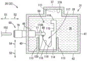
Fig. 1 is a schematic cross-sectional view depicting an internal configuration of a printer including a cartridge holder in an illustrative embodiment according to one or more aspects of the present disclosure.
Fig. 2 is a schematic external perspective view depicting an ink cartridge in an illustrative embodiment according to one or more aspects of the present disclosure.
Fig. 3 is a perspective view depicting an ink tank of an ink cartridge in an illustrative embodiment according to one or more aspects of the present disclosure.
FIG. 4 is a functional block diagram of a printer in an illustrative embodiment according to one or more aspects of the present disclosure.
Fig. 5A is a right side view depicting an ink tank in an illustrative embodiment according to one or more aspects of the present disclosure, wherein the restricting member is in the blocking position and the detecting member is in the standby position.
Fig. 5B is a vertical cross-sectional view depicting an ink tank in an illustrative embodiment according to one or more aspects of the present disclosure, wherein the restricting member is in the restricting position and the detecting member is in the standby position.
Fig. 6A is a right side view depicting an ink tank in an illustrative embodiment according to one or more aspects of the present disclosure, wherein the restricting member is in a non-blocking position and the detecting member is in a standby position.
Fig. 6B is a vertical cross-sectional view depicting an ink tank in an illustrative embodiment according to one or more aspects of the present disclosure, wherein the restricting member is in the release position and the detecting member is in the standby position.
Fig. 7A is a right side view depicting an ink tank in an illustrative embodiment according to one or more aspects of the present disclosure, wherein the restricting member is located at the releasing position and the detecting member is located at the detecting position.
FIG. 7B is a vertical cross-sectional view depicting an ink tank in an illustrative embodiment according to one or more aspects of the present disclosure, wherein the restricting member is in the release position and the detecting member is in the detection position.
Fig. 8A is a perspective view depicting a detection member in an illustrative embodiment according to one or more aspects of the present disclosure.
Fig. 8B is a perspective view depicting a valve, a sealing member, and a restraining member in an illustrative embodiment according to one or more aspects of the present disclosure.
Fig. 9 is a flowchart depicting an exemplary process performed by the controller in an illustrative embodiment according to one or more aspects of the present disclosure for determining whether an abnormality has occurred in the viscosity of ink stored in an ink chamber of an ink tank.
Fig. 10 is a flowchart depicting an exemplary process performed by the controller under the condition that the determination process in fig. 9 has ended and the lid of the cartridge holder is closed in an illustrative embodiment according to one or more aspects of the present disclosure.
FIG. 11 is a flow chart depicting an exemplary process performed by the controller for determining an amount of ink remaining in an ink chamber in an illustrative embodiment according to one or more aspects of the present disclosure.
Fig. 12 is a vertical cross-sectional view depicting an ink outlet in a first variation of an illustrative embodiment according to one or more aspects of the present disclosure.
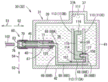
Fig. 13A is a vertical cross-sectional view depicting an ink tank in a first variation of an illustrative embodiment according to one or more aspects of the present disclosure, wherein the restricting member is in the blocking position and the detecting member is in the standby position.
Fig. 13B is a schematic vertical cross-sectional view depicting an ink tank in a first variation of an illustrative embodiment according to one or more aspects of the present disclosure, wherein the restricting member is in the non-blocking position and the detecting member is in the standby position.
Fig. 14A is a schematic vertical cross-sectional view depicting an ink tank in a first variation of an illustrative embodiment according to one or more aspects of the present disclosure, in which the restricting member is located at the releasing position, and the detector 59 is located between the standby position and the detecting position.
Fig. 14B is a schematic vertical cross-sectional view depicting an ink tank in a first variation of the illustrative embodiment according to one or more aspects of the present disclosure, wherein the restricting member is in the release position and the detector 59 is in the detection position.
Fig. 15 is a schematic vertical cross-sectional view depicting an ink tank in a first variation of an illustrative embodiment in accordance with one or more aspects of the present disclosure, wherein the amount of ink remaining in the ink chamber is less than the amount of ink remaining in the ink chamber of fig. 14B.
Fig. 16 is a perspective view depicting a valve and a sealing member in a first variation of an illustrative embodiment according to one or more aspects of the present disclosure.
Fig. 17A is a schematic vertical cross-sectional view depicting an ink tank in a second variation of the illustrative embodiment according to one or more aspects of the present disclosure, wherein the restricting member is in the blocking position and the detector 59 is in the standby position.
Fig. 17B is a schematic vertical cross-sectional view depicting an ink tank in a second variation of the illustrative embodiment according to one or more aspects of the present disclosure, wherein the restriction member is in the non-blocking position and the detector 59 is in the standby position.
Fig. 18A is a schematic vertical cross-sectional view depicting an ink tank in a second variation of the illustrative embodiment according to one or more aspects of the present disclosure, in which the restricting member is located at the releasing position, and the detector 59 is located between the standby position and the detecting position.
Fig. 18B is a schematic vertical cross-sectional view depicting an ink tank in a second variation of the illustrative embodiment according to one or more aspects of the present disclosure, in which the restricting member is located at the releasing position and the detector 59 is located at the detecting position.
Fig. 19 is a schematic vertical cross-sectional view depicting an ink tank in a second variation of an illustrative embodiment in accordance with one or more aspects of the present disclosure, wherein the amount of ink remaining in the ink chamber is less than the amount of ink remaining in the ink chamber of fig. 18B.
Fig. 20A is a schematic vertical cross-sectional view depicting an ink tank in a third variation of the illustrative embodiment in accordance with one or more aspects of the present disclosure, wherein the restricting member is in the blocking position and the detecting member is in the standby position.
Fig. 20B is a schematic vertical cross-sectional view depicting an ink tank in a third variation of the illustrative embodiment according to one or more aspects of the present disclosure, wherein the restriction member is in the non-blocking position and the detector 59 is in the standby position.
Fig. 21A is a schematic vertical cross-sectional view depicting an ink tank in a third variation of the illustrative embodiment according to one or more aspects of the present disclosure, in which the restricting member is located at the releasing position, and the detector 59 is located between the standby position and the detecting position.
Fig. 21B is a schematic vertical cross-sectional view depicting an ink tank in a third variation of the illustrative embodiment according to one or more aspects of the present disclosure, wherein the restricting member is located at the releasing position and the detector 59 is located at the detecting position.
Fig. 22A is a schematic vertical cross-sectional view depicting an ink tank in a fourth variation of the illustrative embodiment in accordance with one or more aspects of the present disclosure, wherein the restricting member is in the blocking position and the detecting member is in the standby position.
Fig. 22B is a schematic vertical cross-sectional view depicting an ink tank in a fourth variation of the illustrative embodiment according to one or more aspects of the present disclosure, wherein the restriction member is in the non-blocking position and the detector 59 is in the standby position.
Fig. 23A is a schematic vertical cross-sectional view depicting an ink tank in a fourth variation of the illustrative embodiment according to one or more aspects of the present disclosure, wherein the restricting member is located at the releasing position, and the detecting member is located between the standby position and the detecting position.
Fig. 23B is a schematic vertical cross-sectional view depicting an ink tank in a fourth variation of the illustrative embodiment in accordance with one or more aspects of the present disclosure, wherein the restricting member is located at the releasing position and the detecting member is located at the detecting position.
Fig. 24A is a schematic vertical cross-sectional view depicting an ink tank in a fifth variation of an illustrative embodiment according to one or more aspects of the present disclosure, wherein the restricting member is in the blocking position and the detecting member is in the standby position.
Fig. 24B is a schematic vertical cross-sectional view depicting an ink tank in a fifth variation of an illustrative embodiment according to one or more aspects of the present disclosure, wherein the restricting member is in the non-blocking position and the detecting member is in the standby position.
Fig. 25A is a schematic vertical cross-sectional view depicting an ink tank in a fifth variation of the illustrative embodiment according to one or more aspects of the present disclosure, wherein the restricting member is located at the releasing position, and the detecting member is located between the standby position and the detecting position.
Fig. 25B is a schematic vertical cross-sectional view depicting an ink tank in a fifth variation of the illustrative embodiment in accordance with one or more aspects of the present disclosure, wherein the restricting member is located at the releasing position and the detecting member is located at the detecting position.
Fig. 26 is a schematic vertical cross-sectional view depicting an ink tank in a fifth variation of an illustrative embodiment in accordance with one or more aspects of the present disclosure, wherein the amount of ink remaining in the ink chamber is less than the amount of ink remaining in the ink chamber of fig. 25B.
Fig. 27 is a right side view depicting an ink tank in another variation of the illustrative embodiments in accordance with one or more aspects of the present disclosure, wherein a radius of curvature of a surface of the float is greater than a radius of curvature of a surface of the second inner wall.
FIG. 28 is a perspective view of an ink tank including a fourth inner wall in yet another variation of an illustrative embodiment according to one or more aspects of the present disclosure.
Fig. 29 is a right side view depicting an ink tank in yet another variation of the illustrative embodiments in accordance with one or more aspects of the present disclosure, wherein the float penetrates the second inner wall through an opening thereof.
Fig. 30A is a vertical cross-sectional view depicting a cartridge holder including a plurality of sensors and an ink cartridge including a plurality of raised portions in another variation of the illustrative embodiments according to one or more aspects of the present disclosure.
Fig. 30B is a vertical cross-sectional view depicting a cartridge holder including a plurality of sensors and an ink cartridge including a plurality of raised portions in another variation of the illustrative embodiments according to one or more aspects of the present disclosure.
Fig. 31A is a vertical cross-sectional view depicting a cartridge holder including a sensor and an ink cartridge including a plurality of convex portions in yet another variation of an illustrative embodiment according to one or more aspects of the present disclosure.
Fig. 31B is a vertical cross-sectional view depicting a cartridge holder including a sensor and an ink cartridge including a plurality of convex portions in yet another variation of the illustrative embodiments according to one or more aspects of the present disclosure.
Fig. 31C is a vertical cross-sectional view depicting a cartridge holder including a sensor and an ink cartridge including a plurality of convex portions in yet another variation of the illustrative embodiments according to one or more aspects of the present disclosure.
Fig. 32 is a perspective view depicting an ink tank of an ink cartridge in yet another variation of an illustrative embodiment according to one or more aspects of the present disclosure.
Detailed Description
Various illustrative embodiments will be described in detail below with reference to the drawings, wherein like reference numerals represent like parts and assemblies throughout the several views. Reference to various embodiments does not limit the scope of the claims appended hereto. Furthermore, any examples set forth in the specification are not intended to be limiting and merely set forth some of the many possible embodiments for the appended claims. Throughout the specification, a threshold range may not necessarily have both a specified upper limit and a specified lower limit, but may need to have at least one specified limit (e.g., a specified upper limit or a specified lower limit). For example, when the threshold range has a specified upper limit, the threshold range may include all values less than or equal to the upper limit. Similarly, when a threshold range has a specified lower limit, the threshold range may include all values greater than or equal to the lower limit. In the following description, the direction in which the ink cartridge 30 is inserted into the cartridge holder 110 may be defined as the insertion direction 51. A direction opposite to the insertion direction 51 and in which the ink cartridge 30 is removed from the cartridge holder 110 may be defined as a removal direction 52. In the illustrative embodiment, both the insertion direction 51 and the removal direction 52 may be horizontal directions, but may not be limited thereto. In a state where the ink cartridge 30 is completely placed in the cartridge holder 110, for example, in a state where the ink cartridge 30 is in the use position, the direction of gravity may be defined as the downward direction 53, and a direction opposite to the direction of gravity may be defined as the upward direction 54. When viewed in the removal direction 52, directions orthogonal to the insertion direction 51 and the downward direction 53 may be defined as a rightward direction 55 and a leftward direction 56. Unless otherwise defined, the ink cartridge 30 is assumed to be in the use position.
< overview of Printer 10 >
As depicted in fig. 1, the printer 10 is configured to record an image onto a recording sheet by selectively ejecting ink droplets onto the recording sheet using an inkjet recording system. The printer 10 (as an example of a liquid consuming apparatus) includes a recording head 21 (as an example of a liquid consuming unit), an ink supply unit 100, and an ink tube 20. The ink tube 20 is connected between the recording head 21 and the ink supply unit 100. The ink supply unit 100 includes a cartridge holder 110 (as an example of a holder). The cartridge holder 110 is configured to accommodate one or more ink cartridges 30 (as an example of a liquid cartridge). The cartridge holder 110 has an opening 112 at one end. The ink cartridge 30 is inserted into the cartridge holder 110 through the opening 112 in the insertion direction 51, or is removed from the cartridge holder 110 through the opening 112 in the removal direction 52.
The ink cartridge 30 stores ink (as an example of liquid) to be used in the printer 10. In a state where the ink cartridge 30 is completely placed in the cartridge holder 110, the ink cartridge 30 and the recording head 21 are connected to each other via the ink tube 20. The recording head 21 includes a sub tank 28. The sub tank 28 is configured to temporarily store therein ink supplied from the ink cartridge 30 through the ink tube 20. The recording head 21 selectively ejects ink supplied from the sub-tank 28 from the nozzles 29. For example, the recording head 21 further includes a head control board 17A. The head control board 17A selectively applies a driving voltage to the piezoelectric elements 29A provided for the respective nozzles 29, thereby selectively ejecting ink from the appropriate nozzles 29.
In the printer 10, the feed roller 23 feeds one or more recording sheets one by one from the feed tray 15 into the conveyance path 24. The conveying roller pair 25 further conveys the recording sheet onto a platen 26. The recording head 21 selectively ejects ink onto a recording sheet passing through the platen 26, thereby recording an image onto the recording sheet. Then, the discharge roller pair 27 discharges the recording sheet having passed the platen 26 onto the discharge tray 16 provided at the downstream end of the conveying path 24.
< ink supply Unit 100>
As depicted in fig. 1, the ink supply unit 100 is included in the printer 10. The ink supply unit 100 is configured to supply ink to the recording head 21 of the printer 10. The ink supply unit 100 includes a cartridge holder 110 for accommodating one or more ink cartridges 30. The cartridge holder 110 includes a housing 101, an ink needle 102, a sensor 103 (as an example of a sensor), and a cartridge sensor 107.
In fig. 1, the ink cartridge 30 is completely placed in the cartridge holder 110. That is, the ink cartridge 30 is in the use position. The cartridge holder 110 can accommodate a plurality of (e.g., four) ink cartridges 30 of respective color inks, such as cyan, magenta, yellow, and black. Thus, in the illustrative embodiment, the cartridge holder 110 includes four ink needles 102, four sensors 103, and four cartridge sensors 107 for the respective four color ink cartridges 30. In the following description, a plurality of identical components have the same or similar configurations and functions in the same or similar manner to each other. Therefore, one of the plurality of identical components will be described in detail, and descriptions of the other components will be omitted. When a single ink cartridge 30 is inserted, removed, or placed in cartridge holder 110, one or more other ink cartridges 30 may or may not be placed in cartridge holder 110.
< ink needle 102>
As depicted in fig. 1, the housing 101 has an opening 112 at one end. The housing 101 has an inner back surface 151 at an end opposite the opening 112 thereof. The ink needle 102 protrudes from the inner back surface 151 of the casing 101 in the removal direction 52. The ink needle 102 is provided at a specific position at the inner back surface 151 of the casing 101 so that the ink needle 102 can be directed to the ink outlet 60 (as an example of a liquid outlet) of the corresponding ink cartridge 30 placed in the cartridge holder 110. The ink needle 102 may be a resin hollow tube having a liquid passage inside. The ink needle 102 has an aperture at or near its distal end. The ink tube 20 is connected to the proximal end of the ink needle 102. The ink stored in the ink chamber 36 (as an example of a liquid storage chamber) of the ink cartridge 30 is allowed to flow into the ink tube 20 through the ink needle 102 provided in the ink outlet 60 by insertion. That is, the ink stored in the ink chamber 36 is supplied from the ink cartridge 30 placed in the cartridge holder 110 to the recording head 21 through the ink outlet 60. All the ink needles 102 provided for the ink cartridges 30 of the respective colors have the same or similar configurations and functions in the same or similar manner to each other.
The printer 10 also includes a cover (not depicted) configured to selectively cover and expose the opening 112 of the cartridge holder 110. The cover is supported by one of the housing 101 and a casing (not depicted) of the printer 10, so that the cover can be opened and closed with respect to the cartridge holder 110. When the cover is opened, the opening 112 is exposed to the outside of the printer 10. In this state, the user is allowed to insert one or more ink cartridges 30 into the cartridge holder 110 or remove them from the cartridge holder 110 through the opening 112. When the cover is closed, the opening 112 is covered by the cover and thus is not exposed to the outside of the printer 10. In this state, the user is not allowed to insert any ink cartridge 30 into the cartridge holder 110 or remove it from the cartridge holder 110.
Throughout the specification, the ink cartridge 30 placed in the cartridge holder 110 refers to the ink cartridge 30 at least a part of which is located in the cartridge holder 110 (more specifically, in the casing 101). Therefore, the ink cartridge 30 placed in the cartridge holder 110 includes the ink cartridge 30 inserted into the cartridge holder 110.
The state in which the ink cartridge 30 is completely placed in the cartridge holder 110 refers to a state in which the ink cartridge 30 is at least capable of supplying ink from the ink cartridge 30 to the recording head 21. For example, the fully set state includes a state in which the ink cartridge 30 is in a specific state enabling the printer 10 to perform image recording, for example, a state in which the ink cartridge 30 is held so as not to move relative to the cartridge holder 110, or a state in which the ink cartridge 30 is located inside the cartridge holder 110 and the cover of the cartridge holder 110 is closed. When the ink cartridge 30 is completely placed in the cartridge holder 110, the ink cartridge 30 is in the use position.
< sensor 103>
As depicted in fig. 1, the housing 101 has an inner top surface 152 extending from an upper end of the inner back surface 151 toward the opening 112. The sensor 103 protrudes downward from the inner top surface 152 of the housing 101. The sensor 103 includes a light emitting portion and a light receiving portion. The light emitting portion is spaced apart from the light receiving portion in one of a rightward direction 55 and a leftward direction 56. In a state where the ink cartridge 30 is completely placed in the cartridge holder 110, the convex portion 37 of the ink cartridge 30 is located between the light emitting portion and the light receiving portion. In other words, the light emitting portion and the light receiving portion are provided on opposite sides of the convex portion 37 of the ink cartridge 30 that is completely placed in the cartridge holder 110. In the illustrative embodiment, the optical path along which the light emitted from the light emitting portion travels may coincide with the left- right directions 55, 56.
The sensor 103 is configured to output different detection signals depending on whether or not the light output from the light emitting portion has been received by the light receiving portion. For example, when the light receiving portion does not receive the light emitted from the light emitting portion (for example, when the intensity of the received light is lower than a predetermined intensity), the sensor 103 outputs a low level signal (for example, a signal having a level lower than a threshold level). When the light receiving portion has received the light output from the light emitting portion (for example, when the intensity of the received light is higher than or equal to a predetermined intensity), the sensor 103 outputs a high level signal (for example, a signal having a level higher than or equal to a threshold level). In the illustrative embodiment, the light emitting portion emits light (e.g., visible light or infrared light) that can pass through the wall of the convex portion 37 of the ink cartridge 30 (e.g., the frame 31) but cannot pass through the ink stored in the ink cartridge 30. All the sensors 103 provided for the ink cartridges 30 of the respective colors have the same or similar configurations and functions in the same or similar manner to each other.
< Cartridge sensor 107>
As depicted in fig. 1, the cartridge sensor 107 is disposed above the corresponding ink needle 102 and at the inner back surface 151 of the housing 101. The cartridge sensor 107 is provided at a cartridge placement detection position in a path for inserting the ink cartridge 30 into the cartridge holder 110. The cartridge sensor 107 is configured to output different detection signals to the controller 130 (see fig. 4) depending on whether the ink cartridge 30 is present at the cartridge placement detection position. In the illustrative embodiment, the cartridge sensor 107 is provided at a specific position such that the ink cartridge 30 is located at the cartridge placement detection position when the ink cartridge 30 is completely placed in the cartridge holder 110.
For example, when the cartridge sensor 107 is not pressed by the front end 58 of the cartridge cover 33 of the ink cartridge 30 placed in the cartridge holder 110, the cartridge sensor 107 outputs a low-level signal. When the cartridge sensor 107 is pressed by the front end 58 of the cartridge cover 33, the cartridge sensor 107 outputs a high level signal. In the illustrative embodiment, the cartridge sensor 107 may be a mechanical sensor configured to output a different detection signal depending on whether the cartridge sensor 107 has been pressed by the front end 58 of the cartridge cover 33. However, in other embodiments, an optical sensor may be used as the cartridge sensor 107. All the cartridge sensors 107 provided for the ink cartridges 30 of the respective colors have the same or similar configurations and functions in the same or similar manner to each other.
< ink Cartridge 30>
All the ink cartridges 30 to be placed in the cartridge holder 110 have the same or similar configurations and functions in the same or similar manner to each other. Therefore, one of the ink cartridges 30 will be described in detail. As depicted in fig. 2 and 3, the ink cartridge 30 includes an ink tank 32 and a cartridge cover 33 covering the ink tank 32. The cartridge cover 33 is composed of two members that can engage with each other and sandwich the ink tank 32 therebetween to cover the ink tank 32. As depicted in fig. 2, the lid 33 has two openings 34 and 35. An opening 34 is defined in the top end 57 of the lid 33. The ink tank 32 includes a convex portion 37. The convex portion 37 of the ink tank 32 protrudes outside the tank cover 33 through the opening 34. An opening 35 is defined in the front end 58 of the lid 33. The ink tank 32 also includes an ink outlet 60. The ink outlet 60 of the ink tank 32 protrudes to the outside of the cartridge cover 33 through the opening 35.
In the illustrative embodiment, the cartridge cover 33 allows the convex portion 37 and the ink outlet 60 of the ink tank 32 to protrude to the outside of the cartridge cover 33 through the opening 34 and the opening 35, respectively. However, in other embodiments, the cap 33 may also expose another portion of the ink tank 32 to the outside of the cap 33 and the raised portion 37 and the ink outlet 60, for example.
As depicted in fig. 3, the ink tank 32 includes an ink chamber 36, an ink outlet 60, and a frame 31. The ink tank 32 may be made of transparent or translucent resin. The ink tank 32 is configured to supply ink from the ink chamber 36 to the outside of the ink tank 32 through an ink outlet 60. The ink cartridge 30 is inserted into the cartridge holder 110 along the insertion direction 51 or removed from the cartridge holder 110 along the removal direction 52 while maintaining an upright posture as depicted in fig. 2, for example, while being oriented such that the downward facing surface is considered the bottom of the ink cartridge 30 and the upward facing surface is considered the top of the ink cartridge 30.
As depicted in fig. 3, the frame 31 may have a substantially rectangular outer shape. The frame 31 may be relatively narrow in the left- right directions 55, 56, that is, the size of the frame 31 in both the up-down directions 54, 53 and the insertion-removal direction 51 is larger than the size in the left- right directions 55, 56. The frame 31 includes a front wall 40, a rear wall 41, an upper wall 39, a lower wall 42, first and second inner walls 43 and 44, and a third inner wall 153. The front wall 40 and the rear wall 41 at least partially overlap each other when viewed in the insertion direction 51 or in the removal direction 52. The upper wall 39 and the lower wall 42 at least partially overlap each other when viewed in the downward direction 53 or in the upward direction 54. The first inner wall 43 stands at a substantially middle portion of the lower wall 42 in the left- right direction 55, 56, extending toward the upper wall 39. The second inner wall 44 protrudes from the first inner wall 43 in the rightward direction 55. The third inner wall 153 abuts the second inner wall 44. The third inner wall 153 is disposed on the right side of the first inner wall 43, and extends from the lower wall 42 toward the upper wall 39. A wall facing forward (e.g., a direction in which the ink cartridge 30 is inserted) when the ink cartridge 30 is inserted into the cartridge holder 110 may be used as the front wall 40, and a wall facing rearward (e.g., a direction in which the ink cartridge 30 is removed) when the ink cartridge 30 is inserted into the cartridge holder 110 may be used as the rear wall 41.
The upper wall 39 is connected between the upper end of the front wall 40 and the upper end of the rear wall 41. A lower wall 42 is connected between the lower end of the front wall 40 and the lower end of the rear wall 41. The convex portion 37 protrudes from the upper wall 39 in the upward direction 54. The upper wall 39 including at least the convex portion 37 allows light emitted from the light emitting portion of the sensor 103 to pass therethrough.
The frame 31 has open ends in the left- right direction 55, 56. The left and right open ends of the frame 31 are sealed by respective films (not depicted). The film for sealing the right opening end of the frame 31 has a shape corresponding to the outline of the frame 31 when viewed in the right direction 55. The film for sealing the left open end of the frame 31 has a shape corresponding to the outline of the frame 31 when viewed in the leftward direction 56. The films constitute right and left walls of the ink chamber 36, respectively. The films are adhered by heating to the right and left ends of the upper wall 39, the front wall 40, the rear wall 41, and the lower wall 42, respectively, to tightly close the right and left open ends of the ink chamber 36. Thus, the ink chamber 36 is defined by the upper wall 39, the front wall 40, the rear wall 41, the lower wall 42, and the film, and thus is able to store ink therein.
The ink tank 32 also includes a protrusion 48 inside the frame 31. The projection 48 extends from the first inner wall 43 in the rightward direction 55. A detector 59 (an example of a part of the first movable member) is provided inside the ink chamber 36. The projection 48 supports the detector 59.
< ink Chamber 36>
As depicted in fig. 3, the ink chamber 36 is defined between a front wall 40 and a rear wall 41. The ink chamber 36 stores therein ink. The ink chamber 36 of the ink cartridge 30 is maintained at a negative pressure before the ink cartridge 30 is placed in the cartridge holder 110. By placing the ink cartridge 30 in the cartridge holder 110, the ink chamber 36 becomes exposed to the outside air through the first air communication passage 66 and the second air communication passage 67. By placing ink cartridge 30 in cartridge holder 110, ink stored in ink chamber 36 is also allowed to flow to the outside of ink cartridge 30 through ink outlet 60. The convex portion 37 is made of a translucent material and has an internal space inside thereof, and the internal space constitutes a part of the ink chamber 36.
< ink outlet 60>
As depicted in fig. 5A and 5B, the ink outlet 60 is provided at the lower end portion of the front wall 40. The ink outlet 60 includes a cylindrical wall 46, a seal 76, and a cap 79. The cylindrical wall 46 may have a tubular shape with a valve chamber 47 therein. The seal 76 and the cap 79 are attached to the cylindrical wall 46.
A cylindrical wall 46 extends between the interior of the ink chamber 36 and the exterior of the ink chamber 36. The cylindrical wall 46 has an opening 46A and an opening 46B (as an example of a liquid outlet) at opposite ends in the insertion- removal directions 51, 52. More specifically, the cylindrical wall 46 has an opening 46A at one end (e.g., an end located inside the ink chamber 36) facing the direction in which the ink cartridge 30 is removed. The cylindrical wall 46 has an opening 46B at the other end facing the direction in which the ink cartridge 30 is inserted (e.g., the other end (e.g., exposed end) located outside the ink chamber 36). With this configuration, the ink chamber 36 communicates with the outside of the ink cartridge 30 through the valve chamber 47. Thus, the ink outlet 60 allows the ink stored in the ink chamber 36 to flow to the outside of the ink cartridge 30. The exposed end (e.g., distal end) of the cylindrical wall 46 is attached to the seal 76 and the cap 79.
As depicted in fig. 3 and 5A, the valve chamber 47 is connected with a first air communication passage 66 and a second air communication passage 67. The first air communication passage 66 allows air to flow between the valve chamber 47 and the outside of the ink cartridge 30. That is, the first air communication passage 66 allows the valve chamber 47 to be exposed to the outside air. The first air communication passage 66 has a hole 66A, a groove 66B, and a hole 66C. The bore 66A provides communication between the interior and exterior of the cylindrical wall 46. One end of the groove 66B communicates with the hole 66A. The hole 66C provides communication between the other end of the groove 66B and the outside of the ink cartridge 30.
The second air communication passage 67 allows air to flow between the valve chamber 47 and the ink chamber 36. The second air communication passage 67 has a hole 67A, a groove 67B, and a hole 67C. The bore 67A provides communication between the interior and exterior of the cylindrical wall 46. One end of the groove 67B communicates with the hole 67A. The hole 67C provides communication between the other end of the groove 67B and the ink chamber 36. The aperture 67A is spaced from the aperture 66A in the removal direction 52. The hole 67C is defined at a specific position higher than the liquid level of the ink stored in the ink chamber 36 of the ink cartridge 30 that has not been used. For example, the hole 67C is defined at a position higher than the liquid level of the maximum amount of ink that the ink chamber 36 can store. The first air communication passage 66 and the second air communication passage 67 are liquid-tightly sealed by a film constituting a right wall of the ink cartridge 30.
As depicted in fig. 5B, the seal 76 has a substantially cylindrical shape. The outer diameter of the seal 76 is substantially the same as the outer diameter of the cylindrical wall 46. A seal 76 is attached liquid-tightly to the exposed end of the cylindrical wall 46. The seal 76 has a through hole 68 at substantially the middle thereof. The through hole 68 penetrates the seal 76 in the insertion direction 51. The through hole 68 provides communication between the inside and the outside of the valve chamber 47. The diameter of the through hole 68 is slightly smaller than the outer diameter of the ink needle 102. The seal 76 may be made of an elastic material, such as rubber.
A cap 79 is fitted over the exposed end of the cylindrical wall 46. The cap 79 and cylindrical wall 46 sandwich the seal 76 therebetween. The cap 79 has a through hole 69 at substantially the center thereof. The through hole 69 penetrates the cap 79 in the thickness direction of the cap 79. The diameter of the through hole 69 is larger than that of the through hole 68. The cap 79 comprises an engagement portion (not depicted) protruding in the removal direction 52. The engagement portion of the cap 79 engages with the engagement portion 81 of the front wall 40. A cap 79 retains the seal 76 at the exposed end of the cylindrical wall 46.
< valve 77, seal member 78, and coil spring 87>
As depicted in fig. 5A, 5B, and 8B, the cylindrical wall 46 of the ink outlet 60 accommodates therein the valve 77 (as an example of a second movable member), the seal member 78, and a coil spring 87 (as an example of an urging member). The valve 77, the seal member 78, and the coil spring 87 are configured to selectively switch the state of the ink outlet 60 between a state in which the ink outlet 60 allows ink to flow from the ink chamber 36 to the outside of the ink cartridge 30 through the ink outlet 60 and a state in which the ink outlet 60 prevents ink from flowing from the ink chamber 36 to the outside of the ink cartridge 30 through the ink outlet 60. The valve 77, the seal 78, and the coil spring 87 are also configured to selectively switch the state of the ink outlet 60 between a state in which the ink outlet 60 allows air communication between the ink chamber 36 and the outside of the ink cartridge 30 through the ink outlet 60 and a state in which the ink outlet 60 prevents air communication between the ink chamber 36 and the outside of the ink cartridge 30 through the ink outlet 60.
The valve 77 includes a circular plug 83, a stem 84, a plurality of first protrusions 85, and a plurality of second protrusions 86. The rod 84 extends from the plug 83 in the removal direction 52. The first projection 85 and the second projection 86 project from the rod 84 in respective directions with respect to the diameter direction of the rod 84. Valve 77 is disposed within valve chamber 47 with plug 83 oriented toward the exposed end of cylindrical wall 46. In this state, the valve 77 is selectively movable in the insertion direction 51 or in the removal direction 52. The distal end of the rod 84 opposite the end of the connecting plug 83 protrudes beyond the valve chamber 47 to the ink chamber 36. That is, the valve 77 extends between the ink outlet 60 and the ink chamber 36. However, in other embodiments, for example, the lever 84 may not necessarily protrude beyond the valve chamber 47 to the ink chamber 36. In this case, the valve 77 may be provided in the ink outlet 60.
The valve 77 has an outer diameter less than the inner diameter of the cylindrical wall 46. Thus, the valve 77 can be selectively moved in the insertion direction 51 and the removal direction 52. For example, the valve 77 can be movable between a first position (e.g., the position of the valve 77 depicted in fig. 5B) and a second position (e.g., the position of the valve 77 depicted in fig. 6B). The second position is closer to the rear wall 41 than the first position.
The outer diameter of the plug 83 is slightly larger than the diameter of the through hole 68 of the seal 76. With this configuration, as depicted in fig. 5B, when the valve 77 is in the first position, the plug 83 fits tightly in the through-hole 68 of the seal 76, thereby fluid-tightly sealing the through-hole 68. Thus, the opening 46B of the cylindrical wall 46 is closed. As depicted in fig. 6B, when valve 77 is in the second position, plug 83 is located separate from seal 76. Thus, the opening 46B of the cylindrical wall 46 is opened.
The rod 84 has an outer diameter smaller than the outer diameter of the plug 83.
The plurality of first protrusions 85 includes four first protrusions 85 spaced apart from each other in the circumferential direction of the lever 84. The plurality of second protrusions 86 includes four second protrusions 86 spaced apart from each other in the circumferential direction of the lever 84. The plurality of first protrusions 85 are spaced apart from the plurality of second protrusions 86 in the insertion direction 51 and are disposed adjacent to the plug 83 in the removal direction 52.
The sealing member 78 may be made of an elastic material, such as rubber. As depicted in fig. 5B and 8B, the sealing member 78 includes a cylindrical portion 95, a first sealing portion 96, and a second sealing portion 97. The first seal portion 96 and the second seal portion 97 may be flanged portions that protrude from respective portions of the outer surface of the cylindrical portion 95 in the diametrical direction of the cylindrical portion 95.
The cylindrical portion 95 is provided between the plurality of first projections 85 and the plurality of second projections 86 while the stem 84 of the valve 77 is inserted into the cylindrical portion 95. The inner diameter of the cylindrical portion 95 is larger than the outer diameter of the stem 84. Therefore, in a state where the rod 84 penetrates the cylindrical portion 95, a gap is left between the cylindrical portion 95 and the rod 84. The empty space inside the cylindrical portion 95 is exposed through the gap between every two adjacent first protrusions 85 and the gap between every two adjacent second protrusions 86. With this configuration, the empty space inside the cylindrical portion 95 provides communication through the empty space between the space of the valve chamber 47 that opens to the opening 46A and the other space of the valve chamber 47 that opens to the opening 46B.
The cylindrical portion 95 includes one end in contact with the plurality of first projections 85 and the other end in contact with the plurality of second projections 86. With this configuration, the seal member 78 can be selectively moved together with the valve 77 in the insertion direction 51 and in the removal direction 52 within the valve chamber 47.
The first sealing portion 96 is spaced from the second sealing portion 97 in the insertion direction 51.
The first seal portion 96 and the second seal portion 97 are in airtight and tight contact with the inner surface of the cylindrical wall 46. In a state where the seal member 78 is not provided in the valve chamber 47, the outer diameter of each of the first seal portion 96 and the second seal portion 97 is slightly larger than the inner diameter of the cylindrical wall 46. Therefore, in a state where the seal member 78 is disposed in the valve chamber 47, the first seal portion 96 and the second seal portion 97 are in airtight contact with the inner surface of the cylindrical wall 46 while being elastically deformed in a direction such that the first seal portion 96 and the second seal portion 97 reduce the outer diameters thereof. When the valve 77 is moved in the insertion- removal directions 51, 52, the first seal portion 96 and the second seal portion 97 slide with respect to the inner surface of the cylindrical wall 46.
A coil spring 87 is disposed between the opening 46A and the plurality of second protrusions 86. The coil spring 87 urges the valve 77 in the insertion direction 51. For example, the coil spring 87 urges the valve 77 from the second position toward the first position. Therefore, in the valve chamber 47, the valve 77 is held while being in contact with the seal 76 (see fig. 5B). In other embodiments, for example, another urging member, such as a leaf spring, may be used instead of the coil spring 87. However, an urging member such as a coil spring 87 may not necessarily be provided.
< Detector 59>
As depicted in fig. 3, 5A, and 5B, the detector 59 is disposed within the ink chamber 36. The detector 59 is rotatably supported by the frame 31. The detector 59 includes an axial portion 61, the axial portion 61 having an axis on which the detector 59 rotates. The axial portion 61 has a cylindrical shape. In other embodiments, for example, the axial portion 61 may have a different shape. The axial portion 61 of the detector 59 engages with the projection 48 of the frame 31 by insertion. Thus, the detector 59 is rotatably supported by the frame 31.
As depicted in fig. 3, 5A, 5B, and 8A, the ink cartridge 30 includes a detector 59 and a float 63. In the illustrative embodiment, the float 63 forms part of the detector 59. The detector 59 includes an axial portion 61, a first arm 71, a second arm 72, a third arm 73, a detecting portion 62, a float 63, and a restricting portion 64.
The axial portion 61 is spaced from the second inner wall 44 in the insertion direction 51. The first arm 71 extends from the axial portion 61 in one direction with respect to the diameter direction of the axial portion 61. The second arm 72 extends from the axial portion 61 in the other direction with respect to the diameter direction of the axial portion 61 so as to extend in a direction different from the direction in which the first arm 71 extends. The second arm 72 extends from the axial portion 61 beyond the second inner wall 44 in the removal direction 52 through the recess 45 of the second inner wall 22. The recess 45 is recessed in the leftward direction 56 with respect to the right end of the second inner wall 44. The third arm 73 extends from the axial portion 61 in the other direction with respect to the diameter direction of the axial portion 61 so as to extend in a direction different from the direction in which the first arm 71 and the second arm 72 extend, respectively. The third arm 73 is shorter in length than the second arm 72.
The detecting portion 62 is provided at the distal end of the first arm 71, and is supported by the first arm 71. For example, the detection section 62 is supported by the first arm 71 outside the enclosed area 154 defined by the first inner wall 43, the second inner wall 44, and the third inner wall 153. The detecting portion 62 has a plate-like shape. The detection part 62 may be made of a material blocking light output from the light emitting part. The detection portion 62 is supported by the first arm 71 while being spaced apart from the axis of the detector 59 by a distance L1 (see fig. 5B). In other embodiments, for example, the detection portion 62 may be provided at another portion of the first arm 71. In one example, the detection portion 62 may be disposed at an intermediate portion of the first arm 71 between the distal end and the proximal end of the first arm 71.
More specifically, when the light output from the light emitting portion reaches one of the right and left surfaces of the detecting portion 62, the intensity of the light from the other of the right and left surfaces of the detecting portion 62 and reaching the light receiving portion may be less than a predetermined intensity, for example, zero. For example, the detection section 62 may completely block light traveling in one of the right direction 55 and the left direction 56, may partially absorb light, may deflect light to change the optical path of light, or may completely reflect light. In one example, the detection portion 62 may be made of a resin containing a pigment. In another example, the detection portion 62 may be transparent or translucent and have a prism-like shape for changing the optical path of light. In other examples, the detection part 62 may have a reflective film, such as an aluminum film, on its surface.
The float 63 is disposed at the distal end of the second arm 72 and is supported by the second arm 72. The float 63 may be made of a material having a specific gravity lower than that of the ink stored in the ink chamber 36. The float 63 is disposed within the enclosed region 154. For example, the second inner wall 44 is disposed between the float 63 and the axial portion 61 in the insertion- removal directions 51, 52, and there is no member between the float 63 and the lower wall 42 in the up-down directions 54, 53. When the ink stored in the enclosed region 154 exists between the float 63 and the lower wall 42 in the up-down direction 54, 53, the float 63 and the lower wall 42 face each other, and there is no intervening member or component between the float 63 and the lower wall 42 in the up-down direction 54, 53. The float 63 is supported by the second arm 72 while being spaced apart from the axis of the detector 59 by a distance L2 (see fig. 5A) shorter than the distance L1. In other embodiments, for example, the float 63 may be disposed at another portion of the second arm 72. In one example, the float 63 may be disposed at an intermediate portion of the second arm 72 between the distal end and the proximal end of the second arm 72.
The restriction portion 64 is provided at the distal end of the third arm 73. The restriction portion 64 constitutes a part of the third arm 73 and includes a distal end of the third arm 73. The restriction portion 64 has a flat surface at the distal end of the third arm 73. The restricting portion 64 is configured to contact and separate from a restricting member 88 (an example of a restricting member). In other embodiments, for example, the restriction portion 64 and the third arm 73 may be separate portions. In this case, the restriction portion 64 may be supported by the third arm 73.
The detector 59 is disposed inside the ink chamber 36 with the first arm 71 extending substantially in the upward direction 54, the second arm 72 extending substantially in the removal direction 52, and the third arm 73 extending substantially in the insertion direction 51. As depicted in fig. 5A and 5B, in this orientation, the detector 59 and the coil spring 87 are spaced apart from each other in the insertion- removal directions 51, 52. For example, most of the detector 59 is located closer to the rear wall 41 than the coil spring 87 in the insertion- removal directions 51, 52. More specifically, the second arm 72 of the detector 59 is located closer to the rear wall 41 than the coil spring 87 in the insertion- removal directions 51, 52. That is, the opening 156 through which the second arm 72 penetrates and the second inner wall 44 having the opening 156 and the opening 155 are both spaced apart from the coil spring 87 in the insertion-removal directions 51, 52 (for example, the opening 156 and the second inner wall 44 are both closer to the rear wall 41 than the coil spring 87 in the insertion-removal directions 51, 52).
The detector 59 is movable (e.g., rotatable) between a detection position (e.g., the position of the detector 59 depicted in fig. 7A and 7B) and a standby position (e.g., the position of the detector 59 depicted in fig. 5A and 5B). The standby position is a position different from the detection position. In a state where the ink cartridge 30 is completely placed in the cartridge holder 110, when the detector 59 is located at the detection position, the detection portion 62 is located between the light emitting portion and the light receiving portion of the sensor 103 (see fig. 1). Therefore, the light output from the light emitting portion is blocked by the detection portion 62, so as not to reach the light receiving portion. Therefore, when the detector 59 is located at the detection position, the detection portion 62 is detected by the sensor 103 from the outside of the ink cartridge 30. In a state where the ink cartridge 30 is completely placed in the cartridge holder 110, when the detector 59 is located at a position other than the detection position, the detection portion 62 is not located between the light emitting portion and the light receiving portion of the sensor 103. Therefore, the light output from the light emitting portion reaches the light receiving portion.
< restraining member 88>
As depicted in fig. 5A and 5B, the restriction member 88 is disposed inside the ink chamber 36. The restricting member 88 is supported by the frame 31 so as to be selectively movable in the insertion direction 51 and the removal direction 52. As depicted in fig. 3, 5A, and 5B, the frame 31 of the ink tank 32 includes a guide member 49. The guide member 49 is spaced from the protrusion 48 of the first inner wall 43 in the removal direction 52 and is spaced from the second inner wall 44 in the insertion direction 51. The guide member 49 is provided in a region of the valve 77 that is provided above a portion of the interior of the ink chamber 36 and below the projection 48. The guide members 49 are spaced apart from each other in the up-down direction 54, 53. The guide member 49 extends in the insertion- removal directions 51, 52. The restricting member 88 is provided between the guide members 49 in the up-down direction 54, 53. Therefore, the restricting member 88 is supported by the frame 31 so as to be selectively movable in the insertion direction 51 and the removal direction 52.
As depicted in fig. 5A, 5B, and 8, the restraining member 88 includes a first portion 89 and a second portion 90. The second portion 90 includes a protruding portion 91 at an intermediate portion in the insertion and removal directions 51, 52. From there, the projecting portion 91 projects in the right direction 55. The protruding portion 91 of the second portion 90 protrudes in the right direction 55 with respect to the guide member 49. The portion of the second portion 90 other than the protruding portion 91 is disposed between the guide members 49 in the up-down direction 54, 53, and does not protrude in the right direction 55 with respect to the guide members 49.
The first portion 89 extends in a downward direction 53 from a protruding portion 91 of the second portion 90. The first portion 89 has a through hole 92 defined in a distal end portion thereof. The through hole 92 penetrates the first portion 89 in the insertion and removal directions 51, 52. The valve 77 includes an engaging projection 77A at the other end opposite to the end including the plug 83. The engagement projection 77A of the valve 77 is provided in the through hole 92 by insertion. The diameter of the through hole 92 is slightly smaller than the diameter of the engaging projection 77A. Thus, the engaging projection 77A and the through hole 92 are engaged with each other, whereby the first portion 89 of the restricting member 88 is engaged with the valve 77. With this configuration, when the valve 77 moves in one of the insertion direction 51 and the removal direction 52, the restriction member 88 moves in the same direction (e.g., selectively in the insertion direction 51 and the removal direction 52) together with the valve 77.
The restraining member 88 may be movable between a blocking position (e.g., the position of the restraining member 88 depicted in fig. 5A and 5B) and a non-blocking position (e.g., the position of the restraining member 88 depicted in fig. 6A and 6B). The release position is closer to the rear wall 41 than the restricting position. When the valve 77 is in the first position, the restricting member 88 is in the restricting position. When the valve 77 is in the second position, the restricting member 88 is in the release position. When the valve 77 moves from the first position to the second position, the restricting member 88 moves from the restricting position to the releasing position. When the valve 77 moves from the second position to the first position, the restricting member 88 moves from the releasing position to the restricting position.
When the restriction member 88 is located at the restriction position, the upward facing surface of the protruding portion 91 of the second portion 90 of the restriction member 88 contacts the restriction portion 64 from below the restriction portion 64, and applies an upward force to the restriction portion 64. Therefore, since the restricting member 88 applies an upward urging force, the detector 59 is restricted from rotating in the direction of the arrow 74 (see fig. 5B). That is, the detector 59 is restricted from rotating from the standby position toward the detection position (e.g., in the direction of arrow 74). In the illustrative embodiment, for example, movement (e.g., rotation) of the detector 59 from the standby position is limited, while only allowing the detector 59 to move within backlash or play. The restricting member 88 may not necessarily restrict movement (e.g., rotation) of the detector 59 from the standby position in a direction (e.g., in a clockwise direction of fig. 5B) opposite to a direction (e.g., the direction of arrow 74) in which the detector 59 moves from the standby position toward the detection position.
When the restriction member 88 is located at the release position, the protruding portion 91 of the second portion 90 of the restriction member 88 is located at a position separated from the restriction portion 64 of the detector 59 in the removal direction 52. Thus, the detector 59 is allowed to rotate in the direction of arrow 74. That is, the detector 59 is allowed to rotate from the standby position to the detection position.
< controller 130>
The printer 10 includes a controller 130. As depicted in fig. 4, the controller 130 includes a central processing unit ("CPU") 131, a read only memory ("ROM") 132, a random access memory ("RAM") 133, an electrically erasable programmable ROM ("EEPROM") 134, and an application specific integrated circuit ("ASIC") 135 connected to each other via an internal bus 137. The ROM132 stores various programs used by the CPU131 for controlling various operations or processes. The RAM133 serves as a storage area for temporarily storing data and/or signals to be used by the CPU131 during execution of programs by the CPU131 or a work space for processing data. The EEPROM134 stores settings and flags that need to be maintained after the power of the printer 10 is turned off. The CPU131, the ROM132, the RAM133, the EEPROM134, and the ASIC135 may all be included in a single chip, or may be individually included in a plurality of chips.
The controller 130 drives a motor (not depicted) to rotate the feed roller 23, the conveying roller pair 25, and the discharge roller pair 27. The controller 130 controls the recording head 21 to cause the nozzles 29 to eject ink from the recording head 21. For example, the controller 130 outputs a control signal to the head control board 17A. The control signal indicates the level of the driving voltage applied to the piezoelectric element 29A. The head control board 17A applies a driving voltage specified by a control signal obtained from the controller 130 to the piezoelectric elements 29A provided for the respective nozzles 29, thereby causing the nozzles 29 to eject ink therefrom. The controller 130 controls the display 109 to display thereon information of the printer 10 and one or more ink cartridges 30, as well as various messages.
The controller 130 receives various signals: a detection signal output from the sensor 103, a detection signal output from the cartridge sensor 107, a signal output from the temperature sensor 106, and a signal output from the lid sensor 108. The temperature sensor 106 is configured to output a signal according to the temperature. The measurement point at which the temperature sensor 106 measures the temperature is not limited to a specific point. For example, the temperature sensor 106 may measure the temperature at any point inside the cartridge holder 110 or at any point outside the printer 10. The cover sensor 108 is configured to output different signals depending on whether the cover closes or exposes the opening 112 of the cartridge holder 110.
< ink cartridge 30 put/remove ink cartridge 30 from cartridge holder 110 >
Hereinafter, a description will be provided as to how the valve 77, the restriction member 88, and the detector 59 function in the process of placing the ink cartridge 30 into the cartridge holder 110. In the following description, it is assumed that the amount of ink remaining in the ink chamber 36 is larger than the amount of ink remaining in the ink chamber 36 in the near-empty state.
In a state where the ink cartridge 30 is not placed in the cartridge holder 110, the valve 77 is located at the first position due to the urging force of the coil spring 87, as depicted in fig. 5A and 5B.
When the valve 77 is located at the first position, the valve 77 is brought into contact with the seal 76 by the urging force of the coil spring 87. In this state, the plug 83 is in close contact with the edge of the through hole 68 of the seal 76. Therefore, the through hole 68 is closed, thereby not allowing ink to flow from the ink chamber 36 to the outside of the ink cartridge 30.
When the valve 77 is in the first position, the aperture 66A is located between the first seal portion 96 and the second seal portion 97. Therefore, the second seal portion 97 blocks the communication between the first air communication passage 66 and the second air communication passage 67. Thus, the ink chamber 36 is maintained at a negative pressure.
When the valve 77 is in the first position, the restricting member 88 is in the restricting position. When the restricting member 88 is located at the restricting position, the detector 59 is located at the standby position. Due to the buoyancy of the float 63, a force tending to rotate the detector 59 in the direction of the arrow 74 acts on the detector 59. Therefore, a force tending to move the restricting portion 64 in the downward direction 53 acts on the restricting portion 64. In this state, the protruding portion 91 of the restricting member 88 contacts the restricting portion 64 of the detector 59 from below the restricting portion 64. When the restriction portion 64 is located at the restriction position, the restriction portion 64 is located within the movable range of the restriction member and downstream of the protruding portion 91 in the rotational direction of the detector 59. Therefore, when the restriction member 88 is located at the restriction position, the restriction member 88 applies an external force to the restriction portion 64, the external force acting in a direction opposite to the direction of the arrow 74, which may be the rotational direction of the detector 59 toward the detection position. In other words, when the restriction member 88 is located at the release position, the restriction portion 64 is located within the movable range of the restriction member 88. When the restriction member 88 is located at the restriction position, the restriction member 88 is located on the moving path of the restriction portion 64. Therefore, the restricting portion 64 is not allowed to move into the movable range of the restricting member 88. Therefore, the detector 59 is restricted from rotating from the standby position.
In the illustrative embodiment, the restriction member 88 contacts the restriction portion 64 from below to restrict the detector 59 from moving to the detection position. However, in other embodiments, for example, the protruding portion 91 of the restricting member 88 may contact the restricting portion 64 by moving in the removing direction 52 to restrict the detector 59 from rotating from the standby position.
When the detector 59 is in the standby position, the float 63 is located adjacent the lower wall 42. That is, the float 63 is immersed in the ink stored in the ink chamber 36.
When the detector 59 is located at the standby position, the detecting portion 62 is not located between the light emitting portion and the light receiving portion of the sensor 103. Therefore, the light output from the light emitting portion is allowed to reach the light receiving portion. Therefore, when the detector 59 is located at the standby position, the sensor 103 outputs a high level signal to the controller 130.
When the ink cartridge 30 is not placed at a specific position in the cartridge holder 110, the corresponding cartridge sensor 107 is not pressed by the front end 58 of the cartridge cover 33 of the ink cartridge 30. Accordingly, the cartridge sensor 107 outputs a low level signal to the controller 130.
In this state, the cover of the cartridge holder 110 is opened, and then the ink cartridge 30 is inserted into the cartridge holder 110. That is, the ink cartridge 30 is placed at a specific portion in the cartridge holder 110. In other words, the ink cartridge 30 becomes in the use position.
When the ink cartridge 30 reaches the vicinity of the inner back surface 151 of the cartridge holder 110 by its movement in the insertion direction 51, the front end 58 of the cartridge cover 33 of the ink cartridge 30 presses the corresponding cartridge sensor 107 facing the front end 58. In response to this, the cartridge sensor 107 outputs a high level signal to the controller 130. Therefore, the count for measuring the moving time of the detector 59 is started.
When the ink cartridge 30 reaches the vicinity of the inner back surface 151 of the cartridge holder 110 by its movement in the insertion direction 51, the plug 83 of the valve 77 comes into contact with the corresponding ink needle 102. In this state, as the ink cartridge 30 moves further in the insertion direction 51, the valve 77 is pressed by the reaction force from the ink needle 102. Therefore, the valve 77 moves from the first position to the second position in the removing direction 52 against the urging force of the coil spring 87.
As depicted in fig. 6A and 6B, when the valve 77 is in the second position, the valve 77 is located away from the seal 76, and thus the through-hole 68 is open. Thus, ink is allowed to flow from the ink chamber 36 to the outside of the ink cartridge 30.
When valve 77 is in the second position, apertures 66A and 67A are both located between first seal portion 96 and second seal portion 97. Therefore, the first air communication passage 66 and the second air communication passage 67 communicate with each other. Therefore, the ink chamber 36 communicates with the outside air, whereby the internal pressure of the ink chamber 36 changes from the negative pressure to the atmospheric pressure.
When the valve 77 moves from the first position to the second position in the removal direction 52, the restriction member 88 moves in the removal direction 52 together with the valve 77. For example, the restricting member 88 is moved from the restricting position to the releasing position, whereby the protruding portion 91 of the restricting member 88 is separated from the restricting portion 64 of the detector 59. Thus, the detector 59 becomes freely rotatable from the standby position.
When the detector 59 becomes free to rotate, the detector 59 rotates in the direction of an arrow 75 (e.g., a direction in which the float 63 remaining submerged in ink rises by its buoyancy). That is, when the ink cartridge 30 is in the use position (for example, when the ink cartridge 30 is completely placed in the cartridge holder 110), the detector 59 is rotated from the standby position to the detection position by the float 63 moving upward in response to the movement of the restriction member 88 to the release position.
When the detector 59 is located at the detection position, the restricting portion 64 is located within the movable range of the restricting member 88.
The float 63 is movable by its buoyancy in an upward direction 54, for example in the direction of arrow 75. For example, the float 63 may move in a direction away from the opening 155 defined in the lower end of the second inner wall 44. The float 63 remains moving in the direction of arrow 75 until the second arm 72 contacts a surface 156A (see fig. 3 and 6A) defining one of the edges of the opening 156 of the second inner wall 44. When the second arm 72 is in contact with the surface 156A, the detector 59 is in the detection position, as depicted in fig. 7A and 7B.
When the detector 59 is located at the detection position, the detection portion 62 is located between the light emitting portion and the light receiving portion of the sensor 103, thereby blocking the light output from the light emitting portion from reaching the light receiving portion. Therefore, when the detector 59 is located at the detection position, the sensor 103 outputs a low level signal to the controller 130. For example, the sensor 103 outputs a low-level signal (as an example of a detection signal) indicating the presence of the detector 59 at the detection position. Thus, the count for measuring the moving time of the detector 59 ends. Through this process, the ink cartridge 30 is completely placed in the cartridge holder 110.
Hereinafter, a description will be provided as to how the valve 77, the restriction member 88, and the detector 59 function in removing the ink cartridge 30 from the cartridge holder 110. In the following description, it is assumed that the amount of ink remaining in the ink chamber 36 is larger than the amount of ink remaining in the ink chamber 36 in the near-empty state.
As depicted in fig. 7A and 7B, in a state where the ink cartridge 30 is completely placed in the cartridge holder 110, the valve 77 is located at the second position by the pressing force of the corresponding ink needle 102. When the valve 77 is in the second position, the restricting member 88 is in the release position. When the restricting member 88 is in the release position, the detector 59 is allowed to rotate. In this state, the detector 59 is located at the detection position by the buoyancy of the float 63.
When the ink cartridge 30 is moved in the removing direction 52 to remove the ink cartridge 30 from the cartridge holder 110, the valve 77 is separated from the ink needle 102, whereby the valve 77 is moved from the second position to the first position by the urging force of the coil spring 87. When the valve 77 moves from the second position to the first position, the restricting member 88 moves together with the valve 77 from the release position to the restricting position. When the restriction member 88 is moved from the release position to the restriction position, the protruding portion 91 of the restriction member 88 comes into contact with the restriction portion 64 of the detector 59 located at the detection position within the movable range of the restriction member 88. For example, a surface extending intersecting a surface of the regulating portion 64 that is in contact with the protruding portion 91 of the regulating member 88 at the regulating position is in contact with a surface of the regulating member 88 facing the insertion direction of the ink cartridge 30, whereby the regulating portion 64 is pressed by the protruding portion 91 from the detection position toward the standby position. Accordingly, the detector 59 is rotated in the direction opposite to the direction of the arrow 74 (see fig. 5B). For example, the detector 59 rotates from the detection position to the standby position. In other words, the restricting member 88 allows the detector 59 to rotate to the standby position when the restricting member 88 moves from the releasing position to the restricting position.
Hereinafter, it will be described how the valve 77, the restricting member 88, and the detector 59 operate when the amount of ink remaining in the ink chamber 36 decreases due to consumption of ink in the recording head 21 after the ink cartridge 30 is completely placed in the cartridge holder 110.
The ink stored in the ink chamber 36 is reduced due to consumption of the ink by ink ejection from the nozzles 29 of the recording head 21, and therefore the ink level becomes lower than a part of the float 63. In a state where the ink surface is lower than a part of the float 63, the float 63 moves downward as the ink surface lowers. According to the downward movement of the float 63, the detector 59 rotates in the direction opposite to the direction of the arrow 74 (see fig. 5B). That is, the detector 59 is rotated from the detection position to the standby position, whereby the detection part 62 is not located between the light emitting part and the light receiving part of the sensor 103. Therefore, the light output from the light emitting portion is allowed to reach the light receiving portion. In response to the reception of the light, the sensor 103 outputs a high level signal to the controller 130. Upon receiving the high level signal output from the sensor 103, the controller 130 determines that the amount of ink remaining in the ink chamber 36 becomes a predetermined amount.
In one example, the detection portion 62 may be defined as described below. It is assumed that points a and B exist in a line along the left- right directions 55, 56. The point a emits light, such as visible light or infrared light, toward the point B, and the emitted light travels in one of the right direction 55 and the left direction 56. The intensity of the light emitted at point B without any obstruction is defined as the light intensity I. In a state where the detection portion 62 is located between the point a and the point B in the left- right directions 55, 56, when the amount of ink stored in the ink chamber 36 is a predetermined amount or more, light emitted from the point a and traveling in one of the right direction 55 and the left direction 56 reaches one of the right surface and the left surface of the detector 59. In this case, the intensity of light that comes out of the other of the right and left surfaces of the detector 59 and reaches the point B may be lower than half the light intensity I, e.g., zero. In a state where the detection portion 62 is located between the point a and the point B in the left- right directions 55, 56, when the amount of ink stored in the ink chamber 36 is less than a predetermined amount, light emitted from the point a and traveling in one of the right direction 55 and the left direction 56 reaches one of the right surface and the left surface of the detector 59. In this case, the intensity of light emitted from the other of the right and left surfaces of the detector 59 and reaching the point B may be half or more of the light intensity I.
For example, the light emitting portion of the sensor 103 is disposed at the point a, and the light receiving portion of the sensor 103 is disposed at the point b. The light receiving portion of the sensor 103 may be, for example, a phototransistor. It is assumed that when the light intensity reaching the phototransistor without any blocking is equal to the light intensity I, the value of the collector current of the phototransistor is defined as a value C. In a state where the detection portion 62 is located between the point a and the point B in the left- right directions 55, 56, when the amount of ink stored in the ink chamber 36 is a predetermined amount or more, light emitted from the point a and traveling in one of the right direction 55 and the left direction 56 reaches one of the right surface and the left surface of the detector 59. In this case, when light comes out of the other of the right and left surfaces of the detector 59 and reaches the point B, the value of the collector current of the phototransistor may be less than half of the value, for example, zero. In a state where the detection portion 62 is located between the point a and the point B in the left- right directions 55, 56, when the amount of ink stored in the ink chamber 36 is less than a predetermined amount, light emitted from the point a and traveling in one of the right direction 55 and the left direction 56 reaches one of the right surface and the left surface of the detector 59. In this case, when light comes out of the other of the right and left surfaces of the detector 59 and reaches the point B, the value of the collector current of the phototransistor may be half or more of the value C.
< determination of ink viscosity anomaly by controller 130>
The controller 130 performs processing for determining whether there is an abnormality in the viscosity of the ink stored in the ink chamber 36 of the ink cartridge 30. Referring to the flowcharts of fig. 9, 10, and 11, the ink viscosity abnormality determination process will be described.
When the controller 130 determines that the detection signal output from the cartridge sensor 107 has changed from the low level signal to the high level signal (e.g., yes in step S11), the controller 130 starts counting to measure the movement time of the detector 59 (e.g., step S12). The controller 130 refers to the detection signal at predetermined intervals. When the controller 130 determines that the level of the detection signal referenced at a specific time is different from the level of the detection signal referenced last time, the controller 130 determines that the detection signal output from the cartridge sensor 107 has changed. When the controller 130 determines that the detection signal output from the cartridge sensor 107 has not changed from the low-level signal to the high-level signal (e.g., no in step S11), the controller 130 performs the process of step S20. For example, when a new ink cartridge 30 is not placed in the cartridge holder 110, the controller 130 determines that the detection signal output from the cartridge sensor 107 has changed from the low-level signal to the high-level signal (e.g., no in step S11).
After step S12, the controller 130 determines whether the elapsed time from the start of measuring the movement time exceeds a predetermined maximum time (e.g., step S13). When the controller 130 determines that the elapsed time has exceeded the predetermined maximum time (e.g., yes in step S13), the controller 130 performs the process of step S15. For example, when the viscosity of the ink stored in the ink chamber 36 is relatively extremely high, the controller 130 determines that the elapsed time has exceeded the predetermined maximum time before the controller 130 determines that the detection signal output from the sensor 103 has changed from the high-level signal to the low-level signal (e.g., yes in step S13).
When the controller 130 determines that the elapsed time does not exceed the predetermined maximum time (e.g., no in step S13), the controller 130 determines whether the detection signal output from the sensor 103 has changed from a high-level signal to a low-level signal (e.g., step S14). When the controller 130 determines that the detection signal output from the sensor 103 has not changed from the high-level signal to the low-level signal (e.g., no in step S14), the controller 130 performs the process of step S13 again. When the controller 130 determines that the detection signal output from the sensor 103 has changed from the high level signal to the low level signal (e.g., yes in step S14), the controller 130 ends counting to measure the movement time of the detector 59 and determines the movement time of the detector 59 (e.g., step S15). When the controller 130 determines that the elapsed time has exceeded the predetermined maximum time (e.g., yes in step S13), the controller 130 determines the predetermined maximum time as the movement time of the detector 59.
The moving time may be a time period that elapses from the time at which the detection signal output from the cartridge sensor 107 changes from the low-level signal to the high-level signal (e.g., yes in step S11) until the detection signal output from the sensor 103 changes from the high-level signal to the low-level signal.
More strictly speaking, the switching of the detection signal output from the cartridge sensor 107 from the low-level signal to the high-level signal may not occur simultaneously with the detector 59 becoming able to rotate from the standby position to the detection position due to being disengaged from the restriction member 88. However, switching of the detection signal output from the cartridge sensor 107 from the low level signal to the high level signal occurs in the vicinity of the release of the detector 59. Therefore, the timing at which the detector 59 becomes rotatable from the standby position to the detection position can be regarded as the timing at which the detection signal output from the cartridge sensor 107 changes from the low-level signal to the high-level signal. Therefore, after the controller 130 receives the high level signal from the cartridge sensor 107, the controller 130 counts to measure the time elapsed until the controller 130 receives the low level signal from the sensor 103, and regards the measured time as the moving time of the detector 59, i.e., the time required for the detector 59 to move from the standby position to the detection position.
After step S15, the controller 130 resets the abnormality flag (e.g., the controller 130 sets the abnormality flag to off) (e.g., step S16). As a result of determining whether the movement time is included in the threshold range (e.g., step S18), when the movement time is not included in the threshold range (e.g., no in step S18), the abnormality flag is set to on. The abnormality flag may be a value assigned based on the ink cartridge 30. The controller 130 stores the abnormality flag of each ink cartridge 30 in the EEPROM 134.
After step S16, the controller 130 determines a threshold range based on the signal output from the temperature sensor 106 (e.g., step S17). The threshold range is used for comparison with the moving time measured in step S15 in order to estimate the viscosity of the ink stored in the ink chamber 36. When the temperature specified by the signal output from the temperature sensor 106 indicates a higher temperature, the controller 130 assigns a lower value to at least one of the upper limit and the lower limit of the threshold range. In other words, when the temperature specified by the signal received from the temperature sensor 106 indicates a lower temperature, the controller 130 assigns a higher value to at least one of the upper and lower limits of the threshold range.
After step 17, the controller 130 determines whether the moving time measured in step S15 is included in the threshold range determined in step S17 (e.g., step S18). When the movement time is below the lower limit of the threshold range, the ink viscosity is estimated to be lower than the normal ink viscosity. When the travel time is higher than the upper limit of the threshold range, the ink viscosity is estimated to be higher than the normal ink viscosity. When the controller 130 determines that the movement time is outside the threshold range (e.g., no in step S18), the controller 130 sets the abnormality flag to on (e.g., step S19). When the controller 130 determines that the movement time is included in the threshold range (e.g., yes in step S18), the routine skips the process of step S19.
The controller 130 determines whether a signal indicating that the lid of the cartridge holder 11 is closed is output from the lid sensor 108 (e.g., step S20). When the controller 130 determines that the cover is open (e.g., no in step S20), the controller 130 performs the processing of step S11 and subsequent steps again. When the controller 130 determines that the cover is closed (e.g., yes in step S20), the controller 130 determines whether a predetermined time has elapsed since the controller 130 determined that the cover is closed in step S20 (e.g., step S21).
When the controller 130 determines that the predetermined time has elapsed (for example, yes in step S21), the controller 130 ends the ink viscosity abnormality determination process of fig. 9. When the controller 130 determines that the predetermined time has not elapsed (e.g., no in step S21), the controller 130 performs the processing of step S11 and subsequent steps. When the controller 130 determines that the cover is open (e.g., no in step S20) during the process of looping step S11 and subsequent steps, the controller 130 ends counting to measure an elapsed time when it determines that the cover is closed (e.g., yes in step S20).
After the ink viscosity abnormality determination process of fig. 9, the controller 130 repeatedly executes the process of fig. 10 at predetermined intervals on the condition that a signal indicating the lid closing of the cartridge holder 11 is output from the lid sensor 108.
The controller 130 determines whether the detection signal output from the cartridge sensor 107 is a high level signal (e.g., step S31). When the controller 130 determines that the detection signal output from the cartridge sensor 107 is a low-level signal (e.g., no in step S31), the controller 130 notifies that the ink cartridge 30 is not present (e.g., step S38), and ends the processing of fig. 10. For example, the notification may be accomplished by displaying a message on the display 109 of the printer 10 or outputting voice guidance from a speaker (not depicted).
When the controller 130 determines that the detection signal output from the cartridge sensor 107 is a high-level signal (e.g., yes in step S31), the controller 130 determines whether the abnormality flag is on (e.g., step S32). When the controller 130 determines that the abnormality flag is "on" (e.g., yes in step S32), the controller 130 notifies information about the ink cartridge 30 (e.g., step S37), and ends the process of fig. 10. For example, deterioration of the ink stored in the ink chamber 36 or a recommendation to replace the ink cartridge 30 may be notified. The notification may be implemented in the same or similar manner as the notification performed in step S38.
When the controller 130 determines that the abnormality flag is off (e.g., no in step S32), the controller 130 executes the remaining amount determination processing of fig. 11 (e.g., step S33). After the remaining amount determining process, the controller 130 determines whether the empty flag is on (e.g., step S34). The empty flag may be set to "on" when the controller 130 determines that the amount of ink remaining in the ink chamber 36 is insufficient to perform image recording.
When the controller 130 determines that the null flag is on (e.g., yes in step S34), the controller 130 ends the process of fig. 10. When the controller 130 determines that the null flag is not on (e.g., no in step S34), the controller 130 determines whether an image recording instruction has been received (e.g., step S35). When the controller 130 determines that the image recording instruction has not been received (e.g., no in step S35), the controller 130 ends the processing of fig. 10. When the controller 130 determines that the image recording instruction has been received (e.g., yes in step S35), the controller 130 directly or indirectly controls the recording head 21, the feed roller 23, the conveying roller pair 25, the discharge roller pair 27 to record the image onto the recording sheet (e.g., step S36), and then ends the process of fig. 10. The process of step S36 may end when image recording is completed for a single recording sheet or when image recording is completed for all the obtained image data.
As described above, when the controller 130 determines that the abnormality flag is on (e.g., yes in step S32), the controller 130 does not perform the image recording of step S36. That is, the routine skips step S36. In other words, the controller 130 does not allow the recording head 21 to eject ink therefrom.
Hereinafter, the remaining amount determination process will be described with reference to fig. 11. The controller 130 determines whether the near empty flag is on (e.g., step S41). When the controller 130 determines that the amount of ink remaining in the ink chamber 36 is relatively low (although sufficient to perform image recording), the near empty flag may be set to "on". That is, the amount of ink remaining in the ink chamber 36 when the near-empty flag is "on" is greater than the amount of ink remaining in the ink chamber 36 when the empty flag is "on".
When the controller 130 determines that the near empty flag is not on (e.g., no in step S41), the controller 130 determines whether the detection signal output from the sensor 103 has changed from the low level signal to the high level signal (e.g., step S42). When the controller 130 determines that the detection signal output from the sensor 103 has not changed (e.g., no in step S42), the controller 130 ends the remaining amount determination processing and executes the processing of step S34 of fig. 10. When the controller 130 determines that the detection signal output from the sensor 103 has changed from the low level signal to the high level signal (e.g., yes in step S42), the controller 130 sets the near empty flag to on (e.g., step S43). Subsequently, the controller 130 notifies that the ink cartridge 30 is in a nearly empty state (e.g., step S44), and ends the remaining amount determination process of fig. 11. Thereafter, the controller 130 executes the process of step S34 of fig. 10. The near empty state refers to a state of the ink chamber 36 when the amount of ink remaining in the ink chamber 36 is relatively low but sufficient to perform image recording.
In step S41, when the controller 130 determines that the near empty flag is on (e.g., yes in step S41), the controller 130 determines whether the software count value is greater than or equal to a predetermined value since the near empty flag was set to on (e.g., step S45). The software count value may be obtained based on data supplied when the controller 130 supplies the ink ejection instruction to the recording head 21. More specifically, the software count value may be obtained by the controller 130 commanding a cumulative count of a product value of the number of ink droplets ejected therefrom by the recording head 21 and the ink amount of each ink droplet specified by the controller 130. The predetermined value may be used for comparison with a software count value.
When the controller 130 determines that the software count value is smaller than the predetermined value since the near empty flag is set to on (e.g., no in step S45), that is, when the controller 130 determines that the amount of ink consumed by the recording head 21 since the near empty flag is set to on is smaller than the predetermined value (e.g., no in step S45), the controller 130 executes the process of step S44.
When the controller 130 determines that the software count value is greater than or equal to the predetermined value since the near empty flag was set to on (e.g., yes in step S45), that is, when the controller 130 determines that the amount of ink consumed by the recording head 21 since the near empty flag was set to on is greater than or equal to the predetermined value (e.g., yes in step S45), the controller 130 sets the empty flag to on (e.g., step S46). Subsequently, the controller 130 notifies that the ink cartridge 30 is in an empty state (e.g., step S47), and ends the remaining amount determination process of fig. 11. Thereafter, the controller 130 executes the process of step S34 of fig. 10. The empty state refers to a state of the ink chamber 36 when the amount of ink remaining in the ink chamber 36 is insufficient to perform image recording.
In steps S44 and S47, in one example, the notification may be accomplished by, for example, displaying a message on the display 109 of the printer 10 or outputting voice guidance from a speaker (not depicted).
< effects obtained by illustrative examples >
According to the illustrative embodiment, the detector 59 moves from the standby position to the detection position when the restricting member 88 moves from the restricting position to the releasing position. The detector 59 moves through the ink while receiving viscous and inertial resistance from the ink, whereby the moving speed of the detector 59 depends on the ink viscosity. Therefore, the viscosity of the ink stored in the ink cartridge 30 can be estimated by measuring the time elapsed from the time when the restriction member 88 reaches the release position to the time when the detector 59 reaches the detection position. According to the ink cartridge 30 of the illustrative embodiment, since the restricting member 88 is returned from the releasing position to the restricting position, the movement of the detector 59 is restricted again in the standby position. Therefore, the repeated return of the restriction member 88 to the restriction position may enable repeated estimation of the viscosity of the ink stored in the ink cartridge 30. In the illustrative embodiment, when the detected portion 60 is located at the detection position, the restricting portion 64 is located within the movable range of the restricting member 88. Therefore, the restriction member 88 can easily act on the restriction portion 64 when the restriction member 88 is returned from the release position to the restriction position.
For example, such a configuration may enable the level of degradation of the ink stored in the ink cartridge 30, which is temporarily not attached to the printer 10, to be estimated. In the case where the cartridge holder 11 can accommodate various types of ink cartridges 30 having respective different viscosities, such a configuration may enable specifying the type of each ink cartridge 30.
According to the illustrative embodiment, when the restricting member 88 is located at the restricting position, the restricting member 88 contacts the detector 59 located at the standby position, thereby reliably restricting the movement of the detector 59 located at the standby position.
According to an illustrative embodiment, distance L1 is longer than distance L2. With this configuration, when the detector 59 rotates between the standby position and the detection position, the detection portion 62 travels longer than the float 63. Thus, component tolerances and/or mounting errors of the components may less affect the measurement of the movement time of the detector 59.
According to the illustrative embodiment, the third arm 73 is shorter than the second arm 72, and therefore, when the restriction portion 64 rotates, the radius of the circle defined by the movement of the restriction portion 64 moves a small distance. Therefore, the distance that the restricting member 88 needs to move in order to release the restriction of the movement of the restricting portion 64 (e.g., the distance from the restricting position to the releasing position) can be reduced, whereby such a configuration can achieve a reduction in the size of the ink cartridge 30 or an increase in the ink storage capacity of the ink cartridge 30. This configuration also enables the moving distance of the float 63 to be increased. Therefore, the moving time of the detector 59 that elapses before the detector 59 reaches the detection position from the standby position can be lengthened, thereby improving the accuracy of the ink viscosity estimation.
According to the illustrative embodiment, the restriction member 88 is engaged with the valve 77. With this configuration, when the valve 77 moves a certain distance between the first position and the second position in a certain direction, the restriction member 88 moves the same distance between the restriction position and the release position in the same direction as the valve 77 (e.g., selectively in the insertion direction 51 and the removal direction 51). Therefore, the configuration of the ink cartridge 30 can be simplified. The moving direction and the moving distance of the valve 77 and the restricting member 88 may not necessarily be the same as each other. In other embodiments, for example, one of the moving direction and the moving distance of the valve 77 may be different from the moving direction and the moving distance of the restricting member 88. In this case, a link mechanism may be provided between the valve 77 and the restriction member 88.
According to the illustrative embodiment, a coil spring 87 is provided that urges the valve 77 from the second position toward the first position. Thus, removal of the external force moving the valve 77 toward the second position may allow the valve 77, the restricting member 88, and the detector 59 to automatically move to the first position, the restricting position, and the standby position, respectively.
According to an illustrative embodiment, the valve 77 closes the opening 46B in the first position and opens the opening 46B in the second position. That is, the valve 77 functions as a valve for closing and opening the opening 46B, thereby reducing the number of parts of the ink cartridge 30.
The float 63 receives relatively high viscous and inertial resistance from the ink as it moves within the enclosed region 154. Therefore, the time that elapses from the time when the regulating member 88 reaches the release position to the time when the detector 59 reaches the detection position becomes long, thereby improving the accuracy of ink viscosity estimation. In the enclosed area 154A, the space defined by the float 63 and the detector 59 located at the standby position is smaller than the space defined by the float 63 and the detector 59 located at the detection position. Therefore, when the detector 59 is located at the standby position, entry of air bubbles from the ink chamber 36 into the enclosed region 154 can be reduced. Therefore, it is possible to restrict a change in the moving speed of the detector 59 which may be caused by the adhesion of the air bubbles to the float 63.
For example, such a configuration may enable the level of degradation of the ink stored in the ink cartridge 30, which is temporarily not attached to the printer 10, to be estimated. In the case where the cartridge holder 11 can accommodate various types of ink cartridges 30 having respective different viscosities, such a configuration may enable specifying the type of each ink cartridge 30.
According to the illustrative embodiment, the second inner wall 44 extends along the path of movement of the float 63. Therefore, the float 63 receives higher viscosity and inertial resistance from the ink stored in the enclosed region 154. Therefore, the moving time of the detector 59 that elapses before the detector 59 reaches the detection position from the standby position can become longer, thereby improving the accuracy of ink viscosity estimation.
According to an illustrative embodiment, an opening 155 is defined in the second interior wall 44 facing the ink outlet 60. Thus, this configuration may allow ink to flow easily from the enclosed area 154 through the opening 155 into the ink outlet 60.
According to the illustrative embodiment, the float 63 serving as the resisting unit is disposed within the enclosed region 154, and therefore, adhesion of air bubbles to the float 63 can be reduced. Therefore, the variation in the moving speed of the detector 59 can be reduced, thereby limiting the decrease in the accuracy of the ink viscosity estimation.
According to the illustrative embodiment, no member or component is provided between the float 63 and the lower wall 42 in the up-down direction 54, 53. Therefore, the float 63 can reach in close proximity to the lower wall 42, whereby the amount of ink remaining in the enclosed region 154 can be reduced.
In the illustrative embodiment, the float 63 forms part of the detector 59 and functions as a resisting unit. However, in other embodiments, another portion of the detector 59 may correspond to a rejection unit, for example. In one example, the detection portion 62 may be disposed in an enclosed region, which may be disposed separately from the ink chamber 36 and defined by walls. In this case, the detection portion 62 may function as a resisting unit. In another example, the entire portion of the detector 59 may be disposed in an enclosed region, which may be disposed separately from the ink chamber 36 and defined by walls. In this case, the detection portion 62 may function as a resisting unit. As described above, at least a portion of the detector 59 may be required to function as a rejecting unit.
In other embodiments, for example, the surface 44A (see fig. 27) of the second inner wall 44 defining the enclosed region 154 may not necessarily include a smooth surface. In one example, the surface 44A may include a plurality of ribs thereon. The ribs may be spaced apart from each other at predetermined intervals in the left- right direction 55, 56, and extend along the moving direction of the float 63. In another example, the ribs may be spaced apart from each other at predetermined intervals in the moving direction of the float 63 and extend in the left- right directions 55, 56. In yet another example, surface 44A may include a plurality of protrusions spaced apart from one another or a plurality of depressions spaced apart from one another, or surface 44A may include a textured surface.
According to the above configuration, when the float 63 moves in the surrounding area 154, the uneven surface 44A can reduce or prevent the float 63 from coming into surface contact with the second inner wall 44. Accordingly, this configuration can reduce or prevent the interruption of the movement of the float 63.
As depicted in fig. 27, the float 63 includes a surface 63A facing the second inner wall 44, and the second inner wall 44 includes a surface 44A facing the float 63. When it is assumed that the surface 63A is an arc having a first radius of curvature and the surface 44A is an arc having a second radius of curvature, it may be preferable that: the first radius of curvature is greater than the second radius of curvature. In other examples, the first radius of curvature may be less than or equal to the second radius of curvature.
When the first radius of curvature is greater than the second radius of curvature, the float 63 and the second inner wall 44 may reduce or prevent surface contact with each other.
In the illustrative embodiment, the upper end of the enclosure region 154 is open to provide communication between the enclosure region 154 and the ink chamber 36 through the upper end. However, in other embodiments, the upper end of the enclosed region 154 may be closed to the ink chamber 36. As depicted in fig. 28, the frame 31 further includes a fourth inner wall 159. The fourth inner wall 159 is connected between the upper ends of the first, second and third inner walls 43, 44 and 153. The fourth inner wall 159 also abuts the rear wall 41. With this configuration, the upper end of the surrounding area 154 is closed to the ink chamber 36 by the fourth inner wall 159.
Thus, this configuration may reduce the entry of air bubbles from the ink chamber 36 into the enclosed region 154.
In the illustrative embodiment, the second arm 72 extends from the ink chamber 36 to the enclosed region 154 through the opening 156 of the second inner wall 44. However, in other embodiments, for example, the second arm 72 may extend from the ink chamber 36 to the enclosed region 154 via an upper open end of the enclosed region 154. In the case where the upper end of the surrounding area 154 is closed to the ink chamber 36 by the fourth inner wall 159, the fourth inner wall 159 may have an opening that may allow the second arm 72 to pass through. In this case, the second arm 72 may extend from the ink chamber 36 to the enclosed region 154 through the opening of the fourth inner wall 159.
In other embodiments, for example, a portion of the detector 59 may be located at the opening 155 of the second inner wall 44 when the detector 59 is in the standby position. In one example, a portion of the float 63 can be located at the opening 155 of the second inner wall 44. In this case, the size of the opening 155 in the left- right directions 55, 56 may be longer than the size of the float 63 of the detector 59 in the left- right directions 55, 56. In this case, the opening 155 is a notch. As depicted in fig. 29, the float 63 may be elongated in the insertion direction 51, and have a dimension in the insertion direction 51 that is greater than the dimension of the float 63 of the illustrative embodiment in the insertion direction 51. When the detector 59 including such a float 63 is located at the standby position, an elongated end of the float 63, which may point in the direction in which the ink cartridge 30 is inserted, may protrude through the opening 155 to the ink chamber 36. The elongated end of the float 63 may retreat from the opening 155 to the enclosed region 154 when the detector 59 rotates from the standby position to the detection position.
As depicted in fig. 32, in other embodiments, for example, the frame 31 may not necessarily include the third inner wall 153. In one example, the enclosed region 154 may be defined by the first inner wall 43, the second inner wall 44, and the membrane (instead of the third inner wall 153).
< first modification >
In the illustrative embodiment, the detector 59 is configured to move between the detection position and the standby position by rotation thereof. However, in other embodiments, for example, the detector 59 may be configured to move between the detection position and the standby position in another manner.
As depicted in fig. 13A and 13B, the ink tank 32 includes an ink chamber 36, an ink outlet 60, and a frame 31. The ink tank 32 may be made of transparent or translucent resin. The ink tank 32 is configured to supply ink from the ink chamber 36 to the outside of the ink tank 32 through an ink outlet 60. The ink cartridge 30 is inserted into the cartridge holder 110 along the insertion direction 51, or removed from the cartridge holder 110 along the removal direction 52 while being held in an upright posture similar to the ink cartridge 30 of the illustrative embodiment depicted in fig. 2, for example, while being oriented such that the downward facing surface is considered the bottom of the ink cartridge 30 and the upward facing surface is considered the top of the ink cartridge 30.
The frame 31 may have a substantially rectangular outer shape. The frame 31 may be relatively narrow in the left- right directions 55, 56, that is, the size of the frame 31 in both the up-down directions 54, 53 and the insertion-removal direction 51 is larger than the size in the left- right directions 55, 56. The frame 31 includes a front wall 40 (as another example of the first wall), a rear wall 41 (as another example of the second wall), an upper wall 39, and a lower wall 42. The front wall 40 and the rear wall 41 at least partially overlap each other when viewed in the insertion direction 51 or in the removal direction 52. The upper wall 39 and the lower wall 42 at least partially overlap each other when viewed in the downward direction 53 or in the upward direction 54. A wall facing forward (e.g., a direction in which the ink cartridge 30 is inserted) when the ink cartridge 30 is inserted into the cartridge holder 110 may be used as the front wall 40, and a wall facing rearward (e.g., a direction in which the ink cartridge 30 is removed) when the ink cartridge 30 is inserted into the cartridge holder 110 may be used as the rear wall 41.
The upper wall 39 is connected between the upper end of the front wall 40 and the upper end of the rear wall 41. A lower wall 42 is connected between the lower end of the front wall 40 and the lower end of the rear wall 41. The convex portion 37 protrudes from the upper wall 39 in the upward direction 54. The upper wall 39 including at least the convex portion 37 allows light emitted from the light emitting portion of the sensor 103 to pass through the upper wall 39.
The frame 31 has open ends in the left- right direction 55, 56. The left and right open ends of the frame 31 are sealed by respective films (not depicted). The film for sealing the right opening end of the frame 31 has a shape corresponding to the outline of the frame 31 when viewed in the right direction 55. The film for sealing the left open end of the frame 31 has a shape corresponding to the outline of the frame 31 when viewed in the leftward direction 56. The films constitute right and left walls of the ink chamber 36, respectively. The films are adhered by heating to the right and left ends of the upper wall 39, the front wall 40, the rear wall 41, and the lower wall 42, respectively, to tightly close the right and left open ends of the ink chamber 36. Thus, the ink chamber 36 is defined by the upper wall 39, the front wall 40, the rear wall 41, the lower wall 42, and the film, and thus is able to store ink therein.
The ink tank 32 also includes a protrusion 48 inside the frame 31. The projection 48 extends from the first inner wall 43 in the rightward direction 55. The detector 59 is disposed inside the ink chamber 36. The projection 48 supports the detector 59.
< ink Chamber 36>
As depicted in fig. 13A and 13B, the ink chamber 36 is defined between a front wall 40 and a rear wall 41. The ink chamber 36 stores therein ink. The ink chamber 36 of the ink cartridge 30 is maintained at a negative pressure until the ink cartridge 30 is placed in the cartridge holder 110. By placing the ink cartridge 30 in the cartridge holder 110, the ink chamber 36 becomes exposed to the outside air through the first air communication passage (not depicted) and the second air communication passage (not depicted). By placing ink cartridge 30 in cartridge holder 110, ink stored in ink chamber 36 is also allowed to flow to the outside of ink cartridge 30 through ink outlet 60. The convex portion 37 has an internal space inside thereof, and the internal space constitutes a part of the ink chamber 36.
< ink outlet 60>
As depicted in fig. 13A and 13B, the ink outlet 60 is provided at the front wall 40. As depicted in fig. 12, the ink outlet 60 includes the cylindrical wall 46, a seal 76, and a cap 79. The cylindrical wall 46 may have a tubular shape with a valve chamber 47 therein. The seal 76 and the cap 79 are attached to the cylindrical wall 46.
A cylindrical wall 46 extends between the interior of the ink chamber 36 and the exterior of the ink chamber 36. The cylindrical wall 46 has an opening 46A and an opening 46B (as another example of a liquid outlet) at opposite ends in the insertion- removal directions 51, 52. More specifically, the cylindrical wall 46 has an opening 46A at one end (e.g., an end located inside the ink chamber 36) facing the direction in which the ink cartridge 30 is removed. The cylindrical wall 46 has an opening 46B at the other end facing the direction in which the ink cartridge 30 is inserted (e.g., the other end located outside the ink chamber 36 (e.g., the exposed end)). With this configuration, the ink chamber 36 communicates with the outside of the ink cartridge 30 through the valve chamber 47. Thus, the ink outlet 60 allows the ink stored in the ink chamber 36 to flow to the outside of the ink cartridge 30. The exposed end (e.g., distal end) of the cylindrical wall 46 is attached to the seal 76 and the cap 79.
The valve chamber 47 is connected to the first air communication passage and the second air communication passage. The first air communication passage allows air to flow between the valve chamber 47 and the outside of the ink cartridge 30 through the first air communication passage. That is, the first air communication passage allows the valve chamber 47 to be exposed to the outside air. The first air communication path extends from the first hole to the outside of the ink cartridge 30 via the groove. The first bore provides communication between the interior and exterior of the cylindrical wall 46.
The second air communication passage allows air to flow between the valve chamber 47 and the ink chamber 36. The second air communication passage extends from the second hole to the ink chamber 36 via the groove. The second bore provides communication between the interior and exterior of the cylindrical wall 46. The second hole is spaced from the first hole in the removal direction 52. The second air communication passage is connected to the ink chamber 36 at a position higher than the liquid level of the ink stored in the ink chamber 36 of the ink cartridge 30 that has not been used.
As depicted in fig. 12, the seal 76 has a substantially cylindrical shape. The outer diameter of the seal 76 is substantially the same as the outer diameter of the cylindrical wall 46. A seal 76 is attached liquid-tightly to the exposed end of the cylindrical wall 46. The seal 76 has a through hole 68 at substantially the middle thereof. The through hole 68 penetrates the seal 76 in the insertion direction 51. The through hole 68 provides communication between the inside and the outside of the valve chamber 47. The diameter of the through hole 68 is slightly smaller than the outer diameter of the ink needle 102. The seal 76 may be made of an elastic material, such as rubber.
A cap 79 is fitted over the exposed end of the cylindrical wall 46. The cap 79 and cylindrical wall 46 sandwich the seal 76 therebetween. The cap 79 has a through hole 69 at substantially the center thereof. The through hole 69 penetrates the cap 79 in the thickness direction of the cap 79. The diameter of the through hole 69 is larger than that of the through hole 68. A cap 79 retains the seal 76 at the exposed end of the cylindrical wall 46.
< valve 77, seal member 78, and coil spring 87>
As depicted in fig. 12 and 16, the cylindrical wall 46 of the ink outlet 60 accommodates therein a valve 77 (as an example of a movable member), a seal member 78, and a coil spring 87 (as an example of an urging member). The valve 77, the seal member 78, and the coil spring 87 are configured to selectively switch the state of the ink outlet 60 between a state in which the ink outlet 60 allows ink to flow from the ink chamber 36 to the outside of the ink cartridge 30 through the ink outlet 60 and a state in which the ink outlet 60 prevents ink from flowing from the ink chamber 36 to the outside of the ink cartridge 30 through the ink outlet 60. The valve 77, the seal 78, and the coil spring 87 are also configured to selectively switch the state of the ink outlet 60 between a state in which the ink outlet 60 allows air communication between the ink chamber 36 and the outside of the ink cartridge 30 through the ink outlet 60 and a state in which the ink outlet 60 prevents air communication between the ink chamber 36 and the outside of the ink cartridge 30 through the ink outlet 60.
The valve 77 includes a circular plug 83, a stem 84, a plurality of first protrusions 85, and a plurality of second protrusions 86. The rod 84 extends from the plug 83 in the removal direction 52. The first projection 85 and the second projection 86 project from the rod 84 in respective directions with respect to the diameter direction of the rod 84. Valve 77 is disposed within valve chamber 47 with plug 83 oriented toward the exposed end of cylindrical wall 46. In this state, the valve 77 is selectively movable in the insertion direction 51 or in the removal direction 52. The distal end of the rod 84 opposite the end of the connecting plug 83 protrudes beyond the valve chamber 47 to the ink chamber 36. That is, the valve 77 extends between the ink outlet 60 and the ink chamber 36. However, in other embodiments, for example, the lever 84 may not necessarily protrude beyond the valve chamber 47 to the ink chamber 36. In this case, the valve 77 may be provided in the ink outlet 60.
The valve 77 has an outer diameter less than the inner diameter of the cylindrical wall 46. Thus, the valve 77 can be selectively moved in the insertion direction 51 and the removal direction 52. For example, the valve 77 can be movable between a first position (e.g., the position of the valve 77 depicted in fig. 13A) and a second position (e.g., the position of the valve 77 depicted in fig. 13B). The second position is closer to the rear wall 41 than the first position.
The outer diameter of the plug 83 is slightly larger than the diameter of the through hole 68 of the seal 76. With this configuration, as depicted in fig. 12, when the valve 77 is in the first position, the plug 83 fits tightly in the through-hole 68 of the seal 76, thereby sealing the through-hole 68 fluid-tightly. Thus, the opening 46B of the cylindrical wall 46 is closed. When valve 77 is in the second position, plug 83 is positioned away from seal 76. Thus, the opening 46B of the cylindrical wall 46 is opened.
The rod 84 has an outer diameter smaller than the outer diameter of the plug 83.
As depicted in fig. 16, the plurality of first protrusions 85 includes four first protrusions 85 spaced apart from each other in the circumferential direction of the lever 84. The plurality of second protrusions 86 includes four second protrusions 86 spaced apart from each other in the circumferential direction of the lever 84. As depicted in fig. 12, the plurality of first protrusions 85 are spaced apart from the plurality of second protrusions 86 in the insertion direction 51 and are disposed adjacent to the plug 83 in the removal direction 52.
The sealing member 78 may be made of an elastic material, such as rubber. As depicted in fig. 5B and 8B, the sealing member 78 includes a cylindrical portion 95, a first sealing portion 96, and a second sealing portion 97. The first seal portion 96 and the second seal portion 97 may be flanged portions that protrude from respective portions of the outer surface of the cylindrical portion 95 in the diametrical direction of the cylindrical portion 95.
The cylindrical portion 95 is disposed between the plurality of first projections 85 and the plurality of second projections 86 while the stem 84 of the valve 77 is inserted through the cylindrical portion 95. The inner diameter of the cylindrical portion 95 is larger than the outer diameter of the stem 84. Therefore, in a state where the rod 84 penetrates the cylindrical portion 95, a gap is left between the cylindrical portion 95 and the rod 84. The empty space inside the cylindrical portion 95 is exposed through the gap between every two adjacent first protrusions 85 and the gap between every two adjacent second protrusions 86. With this configuration, the empty space inside the cylindrical portion 95 provides communication through the empty space inside the cylindrical portion 95 between the space of the valve chamber 47 that opens to the opening 46A and the other space of the valve chamber 47 that opens to the opening 46B.
The cylindrical portion 95 includes one end in contact with the plurality of first projections 85 and the other end in contact with the plurality of second projections 86. With this configuration, the seal member 78 can be selectively moved together with the valve 77 in the insertion direction 51 and in the removal direction 52 within the valve chamber 47.
The first sealing portion 96 is spaced from the second sealing portion 97 in the insertion direction 51.
The first seal portion 96 and the second seal portion 97 are in airtight and tight contact with the inner surface of the cylindrical wall 46. In a state where the seal member 78 is not provided in the valve chamber 47, the outer diameter of each of the first seal portion 96 and the second seal portion 97 is slightly larger than the inner diameter of the cylindrical wall 46. Therefore, in the state where the seal member 78 is disposed in the valve chamber 47, the first seal portion 96 and the second seal portion 97 are in airtight contact with the inner surface of the cylindrical wall 46 while being elastically deformed in a direction such that the first seal portion 96 and the second seal portion 97 reduce their outer diameters. When the valve 77 is moved in the insertion- removal directions 51, 52, the first seal portion 96 and the second seal portion 97 slide with respect to the inner surface of the cylindrical wall 46.
A coil spring 87 is disposed between the opening 46A and the plurality of second protrusions 86. The coil spring 87 urges the valve 77 in the insertion direction 51. For example, the coil spring 87 urges the valve 77 from the second position toward the first position. Therefore, in the valve chamber 47, the valve 77 is held while being in contact with the seal 76 (see fig. 12). In other embodiments, for example, another urging member, such as a leaf spring, may be used instead of the coil spring 87. However, an urging member such as a coil spring 87 may not necessarily be provided.
< Detector 59>
As depicted in fig. 13A and 13B, the detector 59 is disposed inside the ink chamber 36. The detector 59 is supported by the frame 31 so as to be movable up and down. The frame 31 of the ink tank 32 includes a guide member 113. The guide member 113 protrudes from the lower wall 42 of the frame 31 in the upward direction 54. The guide member 113 may have a rectangular hollow cylindrical shape. The float 114 of the detector 59 is disposed in the inner space of the guide member 113. Although the detector 59 is movable up and down along the guide member 113, the detector 59 is allowed to move only in the insertion and removal directions 51, 52 and in the left- right directions 55, 56 within the backlash or play. That is, the guide member 113 allows the detector 59 to move linearly in the up-down direction 54, 53. With this configuration, the detector 59 is supported by the frame 31 so as to be movable up and down.
The ink cartridge 30 includes the detector 59 and the float 114. In the first modification, the detector 59 includes a float 114, an arm 115, and a detected portion 116.
The float 114 is restricted from moving in directions other than the downward direction 53 and the upward direction 54 by the guide member 113 while being allowed to move only in backlash or play in directions other than the downward direction 53 and the upward direction 54. The float 114 may be made of a material having a lower specific gravity than the ink stored in the ink chamber 36.
The float 114 has a substantially rectangular parallelepiped shape. The float 114 has an upwardly open cavity 117. The cavity 117 extends from one side of the float 114 to the other (e.g., between the right and left ends). The cavity 117 is defined by a first surface 118 (as an example of an inclined surface) and a second surface 119. The first surface 118 is angled relative to the removal direction 52. The second surface 119 extends in the upward direction 54 adjacent to the first surface 118.
An arm 115 extends from the float 114 in the upward direction 54. The detected part 116 is disposed at the distal end of the arm 115 and supported by the arm 115. The detected part 116 has a plate-like shape. The detected part 116 may be made of a material blocking light output from the light emitting part.
The detector 59 is movable between a detection position (e.g., the position of the detector 59 depicted in fig. 14B) and a standby position (e.g., the position of the detector 59 depicted in fig. 13A) while being guided by the guide member 113. The detection position and the standby position are spaced apart from each other in the vertical direction (e.g., the up-down direction 54, 53). The detection position is higher than the standby position. The guide member 113 allows the detector 59 to be linearly moved selectively in the upward direction 54 and the downward direction 55 between the detection position and the standby position.
When the detector 59 is located at the detection position, the detected portion 116 is located between the light emitting portion and the light receiving portion of the sensor 103. That is, the detected part 116 is located on the optical axis 111 extending between the light emitting part and the light receiving part of the sensor 103. Therefore, the light output from the light emitting portion is blocked by the detected portion 116, so as not to reach the light receiving portion. Therefore, when the detector 59 is located at the detection position, the detected portion 116 is detected by the sensor 103 from the outside of the ink cartridge 30. When the detector 59 is located at a position other than the detection position, the detected portion 116 is not located between the light emitting portion and the light receiving portion of the sensor 103. Therefore, the light output from the light emitting portion reaches the light receiving portion.
< restraining member 88>
As depicted in fig. 13A and 13B, the restriction member 88 is disposed inside the ink chamber 36. The restriction member 88 has a curved surface at its distal end in the removal direction 52. The restraining member 88 is disposed at an end 120 of the stem 84 of the valve 77. End 120 is opposite the end of plug 83 that includes rod 84. Thus, the restriction member 88 is configured to selectively move with the valve 77 in the insertion direction 51 and the removal direction 52. The valve 77 is disposed on the right side of the detector 59 and the guide member 113. The restricting member 88 extends from the end 120 in the leftward direction 56 (see fig. 16). With this configuration, the restraining member 88 is located in the cavity 117 of the float 114.
The restraining member 88 is movable between a blocking position (e.g., the position of the restraining member 88 depicted in fig. 13A) and a non-blocking position (e.g., the position of the restraining member 88 depicted in fig. 13B, 14A, and 14B). The release position is closer to the rear wall 41 than the restricting position. When the valve 77 is in the first position, the restricting member 88 is in the restricting position. When the valve 77 is in the second position, the restricting member 88 is in the release position. When the valve 77 moves from the first position to the second position against the urging force of the coil spring 87, the restriction member 88 moves from the restriction position to the release position. When the valve 77 moves from the second position to the first position, the restricting member 88 moves from the releasing position to the restricting position.
When the restriction member 88 is located at the restriction position, the restriction member 88 contacts the first surface 118 of the float 114 of the detector 59 from above. In this state, the restraining member 88 receives a force having a vector component in the removal direction 52 from the first surface 118 of the cavity 117 due to the buoyancy of the float 114. However, since the urging force of the coil spring 87 acting in the insertion direction 51 is larger than the force of the coil spring 78 acting in the removal direction 52, the restricting member 88 is restricted from moving in the removal direction 52, and thus the detector 59 is restricted from moving in the upward direction 54. That is, the detector 59 is restricted from moving from the standby position. In the first modification, for example, the movement of the detector 59 in the upward direction 54 from the standby position is restricted, while the detector 59 is allowed to move only within the backlash or play at the standby position. The restricting member 88 may not necessarily restrict the movement of the detector 59 in the downward direction 53 from the standby position. In other variations, for example, when the restraining member 88 is in the restraining position, the restraining member 88 may be in contact with the upper surface 114A of the float 114 from above, rather than in contact with the first surface 118.
When the restriction member 88 is located at the release position, the restriction member 88 is located apart from the first surface 118 (see fig. 13B). In this state, the distal end portion of the restraining member 88 in the removal direction 52 is located above the deepest portion of the cavity 117 of the float 114 while being away from the float 114. Therefore, in this state, the detector 59 is allowed to move in the upward direction 54. That is, the detector 59 is allowed to move from the standby position to the detection position.
< ink cartridge 30 put/remove ink cartridge 30 from cartridge holder 110 >
Hereinafter, a description will be provided as to how the valve 77, the restriction member 88, and the detector 59 function in the process of placing the ink cartridge 30 into the cartridge holder 110. In the following description, it is assumed that the amount of ink remaining in the ink chamber 36 is larger than the amount of ink remaining in the ink chamber 36 in the near-empty state.
In a state where the ink cartridge 30 is not placed in the cartridge holder 110, the valve 77 is located at the first position due to the urging force of the coil spring 87, as depicted in fig. 13A.
When the valve 77 is located at the first position, the valve 77 is brought into contact with the seal 76 by the urging force of the coil spring 87. In this state, the plug 83 is in close contact with the edge of the through hole 68 of the seal 76. Therefore, the through hole 68 is closed, thereby not allowing ink to flow from the ink chamber 36 to the outside of the ink cartridge 30.
When the valve 77 is in the first position, the first aperture is located between the first seal portion 96 and the second seal portion 97. Therefore, the second seal portion 97 blocks the communication between the first air communication passage and the second air communication passage. Thus, the ink chamber 36 is maintained at a negative pressure.
When the valve 77 is in the first position, the restricting member 88 is in the restricting position. When the restricting member 88 is located at the restricting position, the detector 59 is located at the standby position. In this state, the restricting member 88 contacts the first surface 118 of the float 114 of the detector 59 from above, thereby restricting the detector 59 from moving from the standby position in the upward direction 54.
When the detector 59 is in the standby position, the float 114 is located adjacent the lower wall 42 of the frame 31. That is, the float 114 is immersed in the ink stored in the ink chamber 36.
When the detector 59 is located at the standby position, the detected part 116 is not located on the optical axis 111 extending between the light emitting part and the light receiving part of the sensor 103. Therefore, the light output from the light emitting portion is allowed to reach the light receiving portion. Therefore, when the detector 59 is located at the standby position, the sensor 103 outputs a high level signal to the controller 130.
When the ink cartridge 30 is not placed at a specific position in the cartridge holder 110, the corresponding cartridge sensor 107 is not pressed by the front end 58 of the cartridge cover 33 of the ink cartridge 30. Accordingly, the cartridge sensor 107 outputs a low level signal to the controller 130.
In this state, the cover of the cartridge holder 110 is opened, and then the ink cartridge 30 is inserted into the cartridge holder 110. That is, the ink cartridge 30 is placed at a specific portion in the cartridge holder 110. In other words, the ink cartridge 30 becomes in the use position.
When the ink cartridge 30 reaches the vicinity of the inner back surface 151 of the cartridge holder 110 by its movement in the insertion direction 51, the front wall 40 of the ink cartridge 30 presses the corresponding cartridge sensor 107. In response to this, the cartridge sensor 107 outputs a high level signal to the controller 130. Therefore, the count for measuring the moving time of the detector 59 is started.
When the ink cartridge 30 reaches the vicinity of the inner back surface 151 of the cartridge holder 110 by its movement in the insertion direction 51, the plug 83 of the valve 77 comes into contact with the corresponding ink needle 102. In this state, as the ink cartridge 30 moves further in the insertion direction 51, the valve 77 is pressed by the reaction force from the ink needle 102. Therefore, the valve 77 moves from the first position to the second position in the removing direction 52 against the urging force of the coil spring 87.
When the valve 77 is in the second position, the valve 77 is positioned away from the seal 76, and thus the through-hole 68 is open. Thus, ink is allowed to flow from the ink chamber 36 to the outside of the ink cartridge 30.
When the valve 77 is in the second position, both the first and second apertures are located between the first and second sealing portions 96, 97. Therefore, the first air communication passage and the second air communication passage communicate with each other. Therefore, the ink chamber 36 communicates with the outside air, whereby the internal pressure of the ink chamber 36 changes from the negative pressure to the atmospheric pressure.
As depicted in fig. 13B, the restricting member 88 moves with the valve 77 in the removal direction 52 as the valve 77 moves from the first position to the second position in the removal direction 52. For example, the restraining member 88 moves from the restraining position to the releasing position, whereby the restraining member 88 is separated from the first surface 118 of the float 114 of the detector 59. Thus, the detector 59 becomes free to move in the upward direction 54 from the standby position.
When the detector 59 becomes movable, the float 114, which has been kept immersed in the ink, moves in the upward direction 54 by its buoyancy. That is, when the ink cartridge 30 is in the use position (for example, when the ink cartridge 30 is completely placed in the cartridge holder 110), the detector 59 is moved from the standby position to the detection position by the float 114 moving upward in response to the movement of the restriction member 88 to the release position.
The float 114 keeps moving in the upward direction 54 until the detected portion 116 comes into contact with the surface 37A defining the inner space of the convex portion 37. Fig. 14A shows the state of the interior of the ink tank 32 after the float 114 starts moving in the upward direction 54 and before the detected portion 116 comes into contact with the surface 37A. When the detected part 116 is in contact with the surface 37A, the detector 59 is located at a detection position (e.g., the position of the detector 59 depicted in fig. 14B). However, in other variations, for example, when the detector 59 is in the detection position, a bottom portion of the cavity 117 of the float 114 may be in contact with the restraining member 88.
When the detector 59 is located at the detection position, the detected portion 116 is located between the light emitting portion and the light receiving portion of the sensor 103. That is, the detected part 116 is located on the optical axis 111 extending between the light emitting part and the light receiving part of the sensor 103. Therefore, the light output from the light emitting portion is not allowed to reach the light receiving portion. Therefore, when the detector 59 is located at the detection position, the sensor 103 outputs a low-level signal (as an example of a detection signal) indicating the presence of the detector 59 at the detection position. Thus, the count for measuring the moving time of the detector 59 ends. Through this process, the ink cartridge 30 is completely placed in the cartridge holder 110.
Hereinafter, a description will be provided as to how the valve 77, the restriction member 88, and the detector 59 function in removing the ink cartridge 30 from the cartridge holder 110. In the following description, it is assumed that the amount of ink remaining in the ink chamber 36 is larger than the amount of ink remaining in the ink chamber 36 in the near-empty state.
As depicted in fig. 14B, in a state where the ink cartridge 30 is completely placed in the cartridge holder 110, the valve 77 is located at the second position by the pressing force of the corresponding ink needle 102. When the valve 77 is in the second position, the restricting member 88 is in the release position. When the restricting member 88 is in the release position, the detector 59 is allowed to move. In this state, the detector 59 is located at the detection position by the buoyancy of the float 114.
A portion of the detector 59 may also preferably be in contact with the guide member 113 when the detector 59 is located at the detection position.
When the ink cartridge 30 is moved in the removing direction 52 to remove the ink cartridge 30 from the cartridge holder 110, the valve 77 is separated from the ink needle 102, whereby the valve 77 is moved from the second position to the first position by the urging force of the coil spring 87. When the valve 77 moves from the second position to the first position, the restricting member 88 moves together with the valve 77 from the release position to the restricting position. When the restricting member 88 moves from the releasing position to the restricting position, the restricting member 88 contacts the first surface 118 of the float 114 of the detector 59. The restricting member 88 moves from the releasing position to the restricting position while contacting the first surface 118 from above. Accordingly, the float 114 is pressed in the downward direction 53 by the restriction member 88, whereby the detector 59 is moved from the detection position to the standby position.
Hereinafter, it will be described how the valve 77, the restricting member 88, and the detector 59 operate when the amount of ink remaining in the ink chamber 36 decreases due to consumption of ink in the recording head 21 after the ink cartridge 30 is completely placed in the cartridge holder 110.
The ink stored in the ink chamber 36 is reduced due to consumption of the ink by ink ejection from the nozzles 29 of the recording head 21, and therefore the ink level becomes lower than a part of the float 114. In a state where the ink level is lower than a part of the float 114, the float 114 moves downward as the ink level lowers. According to the downward movement of the float 114, the detector 59 is moved in the downward direction 53 from the detection position toward the standby position (see fig. 15), whereby the detected part 116 is not located between the light emitting part and the light receiving part of the sensor 103. Therefore, the light output from the light emitting portion is allowed to reach the light receiving portion. In response to the reception of the light, the sensor 103 outputs a high level signal to the controller 130. Upon receiving the high level signal from the sensor 103, the controller 130 determines that the amount of ink remaining in the ink chamber 36 becomes a predetermined amount.
< determination of ink viscosity anomaly by controller 130>
In the first modification, the controller 130 executes processing for determining whether there is an abnormality in the viscosity of the ink stored in the ink chamber 36 of the ink cartridge 30, similar to the ink viscosity abnormality determination processing of the illustrative embodiment.
< effects obtained by the first modification >
According to the first modification, the detector 59 is moved from the standby position to the detection position when the restriction member 88 is moved from the restriction position to the release position. The detector 59 moves through the ink while receiving viscous and inertial resistance from the ink, whereby the moving speed of the detector 59 depends on the ink viscosity. Therefore, the viscosity of the ink stored in the ink cartridge 30 can be estimated by measuring the time elapsed from the time when the restriction member 88 reaches the release position to the time when the detector 59 reaches the detection position. According to the ink cartridge 30 of the first modification, since the restricting member 88 is returned from the releasing position to the restricting position, the movement of the detector 59 is restricted again in the standby position. Therefore, the repeated return of the restriction member 88 to the restriction position may enable repeated estimation of the viscosity of the ink stored in the ink cartridge 30.
For example, such a configuration may enable the level of degradation of the ink stored in the ink cartridge 30, which is temporarily not attached to the printer 10, to be estimated. In the case where the cartridge holder 11 can accommodate various types of ink cartridges 30 having respective different viscosities, such a configuration may enable specifying the type of each ink cartridge 30.
According to the illustrative embodiment, a coil spring 87 is provided that urges the valve 77 from the second position toward the first position. Thus, removal of the external force moving the valve 77 toward the second position may allow the valve 77, the restricting member 88, and the detector 59 to automatically move to the first position, the restricting position, and the standby position, respectively.
According to an illustrative embodiment, the valve 77 closes the opening 46B in the first position and opens the opening 46B in the second position. That is, the valve 77 functions as a valve for closing and opening the opening 46B, thereby reducing the number of parts of the ink cartridge 30.
< second modification >
In the first modification, the restriction member 88 and the valve 77 have an integrated structure. However, in other variations, for example, the restriction member 88 and the valve 77 are separate components.
For example, in the second modification, as depicted in fig. 17A and 17B, the detector 59 is provided inside the ink chamber 36. The detector 59 is supported by the frame 31 so as to be movable up and down. The frame 31 of the ink tank 32 includes a guide member 113. The guide member 113 protrudes from the lower wall 42 of the frame 31 in the upward direction 54. The guide member 113 surrounds the detector 59 on three sides, e.g., a right side, a left side, and a side facing the direction in which the ink cartridge 30 is removed (e.g., a side facing the rear wall 41 of the frame 31). The restricting member 88 is disposed adjacent to the detector 59 in the insertion direction 51. With this configuration, although the detector 59 is movable up and down along the guide member 113, the detector 59 is allowed to move only in the insertion and removal directions 51, 52 and in the left- right directions 55, 56 within the backlash or play. That is, the guide member 113 allows the detector 59 to move linearly in the up-down direction 54, 53. With this configuration, the detector 59 is supported by the frame 31 so as to be movable up and down.
The detector 59 of the second modification has a similar configuration to the detector 59 of the first modification, except that the detector 59 of the second modification does not have the cavity 117 in the float 114 thereof.
As depicted in fig. 17A and 17B, the restriction member 88 is disposed inside the ink chamber 36. The restriction member 88 is disposed between the valve 77 and the detector 59 in the insertion- removal directions 51, 52.
The restraining member 88 includes a body 123 and a protruding portion 124. The body 123 has an inclined surface 122, which inclined surface 122 is angled with respect to the removal direction 52 (e.g., a direction from the front wall 40 towards the rear wall 41) and extends downward in the removal direction 52. The protruding portion 124 protrudes from the body 123 in the removal direction 52.
A coil spring 121 (as another example of the urging member) is provided between the restriction member 88 and the upper wall 39 of the ink tank 32 in the up-down direction 54, 53. One end of the coil spring 121 is connected to the restricting member 88, and the other end is connected to the upper wall 39. This configuration allows the restricting member 88 to move up and down as the coil spring 121 contracts and extends. In other modifications, for example, a leaf spring may be used as the urging member instead of the coil spring 121.
The restraining member 88 is movable between a blocking position (e.g., the position of the restraining member 88 depicted in fig. 17A) and a non-blocking position (e.g., the position of the restraining member 88 depicted in fig. 17B). The release position is higher than the restricting position. When the valve 77 is in the first position, the restricting member 88 is in the restricting position. When the valve 77 is in the second position, the restricting member 88 is in the release position. When the valve 77 moves from the first position to the second position, the restricting member 88 moves from the restricting position to the releasing position. When the valve 77 moves from the second position to the first position, the restricting member 88 moves from the releasing position to the restricting position.
When the restriction member 88 is located at the restriction position, the protruding portion 124 of the restriction member 88 contacts the upper surface 114A of the float 114 of the detector 59 from above. Thus, the detector 59 is restricted from moving in the upward direction 54. That is, the detector 59 is restricted from moving from the standby position. In the second modification, for example, the movement of the detector 59 in the upward direction 54 from the standby position is restricted while the detector 59 is allowed to move only within the backlash or play at the standby position. The restricting member 88 may not necessarily restrict the movement of the detector 59 in the downward direction 53 from the standby position.
When the restricting member 88 is located at the releasing position, the restricting member 88 is located at a position separated from the upper surface 114A of the float 114. Therefore, in this state, the detector 59 is allowed to move in the upward direction 54. That is, the detector 59 is allowed to move from the standby position to the detection position.
Hereinafter, a description will be provided as to how the valve 77, the restriction member 88, and the detector 59 function in the process of placing the ink cartridge 30 into the cartridge holder 110 in the second modification. In the following description, it is assumed that the amount of ink remaining in the ink chamber 36 is larger than the amount of ink remaining in the ink chamber 36 in the near-empty state.
In a state where the ink cartridge 30 is not placed in the cartridge holder 110, the valve 77 of the ink cartridge 30 of the second modification is in the same or similar state as the valve 77 of the ink cartridge 30 of the illustrative embodiment.
When the valve 77 is located at the first position, the valve 77 is located apart from the restricting member 88. In this state, the restricting member 88 is located at the restricting position. When the restricting member 88 is located at the restricting position, the detector 59 is located at the standby position. In this state, the restricting member 88 contacts the upper surface 114A of the float 114 of the detector 59 from above, thereby restricting the detector 59 from moving from the standby position in the upward direction 54.
When the detector 59 is in the standby position, the float 114 is located adjacent the lower wall 42 of the frame 31. That is, the float 114 is immersed in the ink stored in the ink chamber 36.
When the detector 59 is located at the standby position, the detected part 116 is not located on the optical axis 111 extending between the light emitting part and the light receiving part of the sensor 103. Therefore, the light output from the light emitting portion is allowed to reach the light receiving portion. Therefore, when the detector 59 is located at the standby position, the sensor 103 outputs a high level signal to the controller 130.
When the ink cartridge 30 is not placed at a specific position in the cartridge holder 110, the corresponding cartridge sensor 107 is not pressed by the front end 58 of the cartridge cover 33 of the ink cartridge 30. Accordingly, the cartridge sensor 107 outputs a low level signal to the controller 130.
In this state, the cover of the cartridge holder 110 is opened, and then the ink cartridge 30 is inserted into the cartridge holder 110. That is, the ink cartridge 30 is placed at a specific portion in the cartridge holder 110. In other words, the ink cartridge 30 becomes in the use position.
Similar to the illustrative embodiment, when the ink cartridge 30 reaches the vicinity of the inner back surface 151 of the cartridge holder 110 by its movement in the insertion direction 51, the cartridge sensor 107 outputs a high level signal to the controller 130. Therefore, the count for measuring the moving time of the detector 59 is started. In accordance with the movement of the ink cartridge 30 in the insertion direction 51, the valve 77 moves from the first position to the second position, thereby allowing ink to flow from the ink chamber 36 to the outside of the ink cartridge 30. Further, the ink chamber 36 communicates with the outside air, whereby the internal pressure of the ink chamber 36 changes from negative pressure to atmospheric pressure.
As depicted in fig. 17B, when the valve 77 moves from the first position to the second position in the removal direction 52, the inclined surface 122 of the restriction member 88 is pressed by the valve 77. That is, the valve 77 moves from the first position to the second position while coming into contact with the inclined surface 122 from below. Therefore, the restriction member 88 is moved in the upward direction 54 from the restriction position toward the release position against the urging force of the coil spring 121. In this state, the coil spring 121 urges the restriction member 88 downward in the vertical direction toward the restriction position. The restricting member 88 moves toward the release position to be separated from the detector 59 located at the standby position. Thus, the detector 59 becomes free to move in the upward direction 54 from the standby position.
When the detector 59 becomes movable, the float 114, which has been kept immersed in the ink, moves in the upward direction 54 by its buoyancy. That is, when the ink cartridge 30 is in the use position (for example, when the ink cartridge 30 is completely placed in the cartridge holder 110), the detector 59 is moved from the standby position to the detection position by the float 114 moving upward in response to the movement of the restriction member 88 to the release position.
The float 114 keeps moving in the upward direction 54 until the upper surface 114A of the float 114 contacts the protruding portion 124 of the restricting member 88 in the release position. Fig. 17A shows the state of the interior of the ink tank 32 after the float 114 starts moving in the upward direction 54 and before the detected portion 116 comes into contact with the protruding portion 124. When the upper surface 114A of the float 114 comes into contact with the protruding portion 124 of the restricting member 88 located at the release position from below, the detector 59 is located at the detection position (see fig. 17B).
When the detector 59 is located at the detection position, the detected portion 116 is located between the light emitting portion and the light receiving portion of the sensor 103. That is, the detected part 116 is located on the optical axis 111 extending between the light emitting part and the light receiving part of the sensor 103. Therefore, the light output from the light emitting portion is not allowed to reach the light receiving portion. Therefore, when the detector 59 is located at the detection position, the sensor 103 outputs a low level signal to the controller 130, thereby ending the count for measuring the moving time of the detector 59. Through this process, the ink cartridge 30 is completely placed in the cartridge holder 110.
Hereinafter, a description will be provided as to how the valve 77, the restriction member 88, and the detector 59 function in removing the ink cartridge 30 from the cartridge holder 110. In the following description, it is assumed that the amount of ink remaining in the ink chamber 36 is larger than the amount of ink remaining in the ink chamber 36 in the near-empty state.
As depicted in fig. 17B, in a state where the ink cartridge 30 is completely placed in the cartridge holder 110, the valve 77 is located at the second position by the urging force of the corresponding ink needle 102. When the valve 77 is in the second position, the restricting member 88 is in the release position. When the restricting member 88 is in the release position, the detector 59 is allowed to move. In this state, the detector 59 is located at the detection position by the buoyancy of the float 114.
When the ink cartridge 30 is moved in the removing direction 52 to remove the ink cartridge 30 from the cartridge holder 110, the valve 77 is separated from the ink needle 102, whereby the valve 77 is moved from the second position to the first position by the urging force of the coil spring 87 to be separated from the restriction member 88. When the valve 77 is separated from the restriction member 88, the restriction member 88 is moved in the downward direction 53 from the release position to the restriction position by the urging force of the coil spring 121. When the restriction member 88 moves in the downward direction 53, the protruding portion 124 of the restriction member 88 presses the upper surface 114A of the float 114 of the detector 59 in the downward direction 53, whereby the detector 59 moves from the detection position to the standby position.
Hereinafter, it will be described how the valve 77, the restricting member 88, and the detector 59 operate when the amount of ink remaining in the ink chamber 36 decreases due to consumption of ink in the recording head 21 after the ink cartridge 30 is completely placed in the cartridge holder 110.
The ink stored in the ink chamber 36 is reduced due to consumption of the ink by ink ejection from the nozzles 29 of the recording head 21, and therefore the ink level becomes lower than a part of the float 114. In a state where the ink level is lower than a part of the float 114, the float 114 moves downward as the ink level lowers. According to the downward movement of the float 114, the detector 59 is moved in the downward direction 53 from the detection position toward the standby position (see fig. 19), whereby the detected part 116 is not located between the light emitting part and the light receiving part of the sensor 103. Therefore, the light output from the light emitting portion is allowed to reach the light receiving portion. In response to the reception of the light, the sensor 103 outputs a high level signal to the controller 130. Upon receiving the high level signal from the sensor 103, the controller 130 determines that the amount of ink remaining in the ink chamber 36 becomes a predetermined amount.
< third modification >
In the first and second modifications, the detector 59 is configured to move from the standby position to the detection position by the buoyancy of the float 114. However, in other variations, for example, the detector 59 may be configured to move from the standby position to the detection position with the downward movement of the weight 125. An example of this configuration will be described below in a third modification. The common parts have the same reference numerals as those of the above-described illustrative embodiment, first modification, or second modification, and detailed description thereof is omitted.
In a third modification, as depicted in fig. 20, the detector 59 is provided inside the ink chamber 36. The detector 59 is rotatably supported by the frame 31. The detector 59 includes an axial portion 126, a first arm 127, a second arm 128, a detection portion 129, and a restriction portion 138.
The first arm 127 extends from the axial portion 126 in one direction with respect to the diameter direction of the axial portion 126. The second arm 128 extends from the axial portion 126 in the other direction with respect to the diameter direction so as to extend in a direction different from the direction in which the first arm 127 extends.
The detecting portion 129 is provided at the distal end of the first arm 127 and supported by the first arm 127. The detecting portion 129 has a plate-like shape. The detection part 129 may be made of a material blocking light output from the light emitting part. The detection portion 129 is configured to block light output from the light emitting portion in a similar manner to the detection portion 62 of the illustrative embodiment.
A limiting portion 138 is provided at the distal end of the second arm 128. The restriction 138 forms a portion of the second arm 128 and includes a distal end of the second arm 128. The restriction portion 138 is configured to contact and separate from the weight 125. In other variations, for example, the restriction portion 138 and the second arm 128 may be separate portions. In this case, the restriction portion 138 may be supported by the second arm 128.
The detector 59 is disposed inside the ink chamber 36, and the first arm 127 extends obliquely upward in the removal direction 52, and the second arm 128 extends obliquely upward in the insertion direction 51.
The detector 59 is movable (e.g., rotatable) between a detection position (e.g., the position of the detector 59 depicted in fig. 21B) and a standby position (e.g., the position of the detector 59 depicted in fig. 20A). The standby position is a position different from the detection position. When the detector 59 is located at the detection position, the detection portion 129 is located between the light emitting portion and the light receiving portion of the sensor 103. That is, the detection portion 129 is located on the optical axis 111 extending between the light emitting portion and the light receiving portion of the sensor 103. Therefore, the light output from the light emitting portion is blocked by the detecting portion 129, so as not to reach the light receiving portion. Therefore, when the detector 59 is located at the detection position, the detection portion 129 is detected by the sensor 103 from the outside of the ink cartridge 30. When the detector 59 is located at a position other than the detection position, the detection portion 129 is not located between the light emitting portion and the light receiving portion of the sensor 103. Therefore, the light output from the light emitting portion reaches the light receiving portion.
The detector 59 may be made of a material having a higher specific gravity than the ink stored in the ink chamber 36. The first arm 127 is longer than the second arm 128. With this configuration, when the detector 59 is located at the detection position, the first arm 127 tends to move in the direction of the arrow 127A, for example, in the direction in which the first arm 127 moves through the ink closer to the lower wall 42 of the ink cartridge 30, while the second arm 128 tends to move in the direction of the arrow 128A, for example, in the direction in which the second arm 128 moves through the ink away from the lower wall 42 of the ink cartridge 30. As the second arm 128 moves in the direction of arrow 127A, the second arm 128 contacts the bottom surface 125A of the weight 125. When the second arm 128 is in contact with the bottom surface 125A of the weight 125, the detector 59 is located at the standby position.
The weight 125 may be made of a material having a higher specific gravity than the ink stored in the ink chamber 36. The weight 125 is supported by the restriction member 88 inside the ink chamber 36.
The frame 31 of the ink tank 32 includes a guide member 139. The guide members 139 protrude from the upper wall 39 of the frame 31 in the downward direction 53. The guide member 139 surrounds the weight 125 on four sides, such as on the right side, the left side, the side facing the insertion direction of the ink cartridge 30 (e.g., the side facing the rear wall 40 of the frame 31), and the side facing the removal direction of the ink cartridge 30 (e.g., the side facing the rear wall 41 of the frame 31). Although the weight 125 is movable up and down along the guide member 139, the weight 125 is allowed to move only in the insertion- removal directions 51, 52 and the left- right directions 55, 56 within the backlash or play. That is, the guide member 139 allows the weight 125 to move linearly in the up-down direction 54, 53.
The weight 125 is disposed vertically above the second arm 128. Thus, the weight 125 can contact the second arm 128 from above.
The weight 125 is movable between a higher position (e.g., the position of the weight 125 depicted in fig. 20A) and a lower position (e.g., the position of the weight 125 depicted in fig. 21B). In the third modification, the weight 125 is provided on the right or left side of the valve 77, so that the valve 77 is unlikely to interfere with the movement of the weight 125 in the upward direction 54 and the downward direction 53.
When the valve 77 is in the first position, the weight 125 is in a higher position. When the weight 125 is located at the upper position, the weight 125 holds the detector 59 at the standby position by contacting the second arm 128. When the valve 77 is in the second position, the weight 125 is in a lower position. When the weight 125 is located at the lower position, the weight 125 holds the detector 59 at the detection position by contacting the second arm 128 from above. When the valve 77 moves from the first position to the second position, the weight 125 moves from the upper position to the lower position. When the valve 77 moves from the second position to the first position, the weight 125 moves from the lower position to the upper position.
The weight 125 has a cavity 140 that opens downwardly. The cavity 140 extends from one side of the weight 125 to the other (e.g., between the right and left ends). The cavity 140 is defined by a first surface 141 (as an example of an inclined surface) and a second surface 142. The first surface 141 is angled relative to the removal direction 52 (e.g., from the front wall 40 toward the rear wall 41). The first surface 141 extends upward in the removal direction 52. The second surface 142 extends contiguously with the first surface 141 in the downward direction 53.
As depicted in fig. 24A and 24B, the restriction member 88 is provided inside the ink chamber 36. The restriction member 88 is provided at the end 143 of the stem 84 of the valve 77. The end 143 is opposite the end of the plug 83 that includes the rod 84. Thus, the restriction member 88 is configured to selectively move with the valve 77 in the insertion direction 51 and the removal direction 52. The valve 77 is disposed on the right side of the weight 125. The restricting member 88 extends from the end 143 in the leftward direction 56. With this configuration, the restraining member 88 is located in the cavity 140 of the weight 125.
The restraining member 88 is movable between a restraining position (e.g., the position of the restraining member 88 depicted in fig. 20A) and a non-blocking position (e.g., the position of the restraining member 88 depicted in fig. 20B, 21A, and 21B). The release position is closer to the rear wall 41 than the restricting position. When the valve 77 is in the first position, the restricting member 88 is in the restricting position. When the valve 77 is in the second position, the restricting member 88 is in the release position. When the valve 77 moves from the first position to the second position, the restricting member 88 moves from the restricting position to the releasing position. When the valve 77 moves from the second position to the first position, the restricting member 88 moves from the releasing position to the restricting position.
When the restriction member 88 is located at the restriction position, the restriction member 88 supports the weight 125 by contacting the first surface 141 of the weight 125 from below. Thus, the weight 125 is restricted from moving from the upper position in the downward direction 53. In the third modification, for example, the movement of the weight 125 in the downward direction 53 from the upper position is restricted while the weight 125 is allowed to move only in the backlash or play at the upper position. The restraining member 88 may not necessarily restrain the movement of the weight 125 in the upward direction 54 from the upper position. The movement of the weight 125 is restricted by the restricting member 88, whereby the detector 59 is not moved from the standby position. That is, the restricting member 88 indirectly restricts the detector 59 from moving from the standby position. In other variations, for example, when the restraining member 88 is in the restraining position, the restraining member 88 may support the weight 125 by contacting the bottom surface 125A of the weight 125 from below rather than contacting the first surface 141 of the weight 125.
When the restriction member 88 is located at the release position, the restriction member 88 is located at a position separated from the first surface 141 of the weight 125 located at the higher position. Thus, in this state, the weight 125 is allowed to move in the downward direction 53 by gravity. That is, when the restraining member 88 is in the release position, the restraining member 88 allows the weight 125 to move from the upper position to the lower position. The detector 59 is rotated from the standby position to the detection position by the pressure of the weight 125 moved from the upper position to the lower position. In other words, when the restriction member 88 is located at the release position, the restriction member 88 allows the detector 59 to move.
Hereinafter, a description will be provided as to how the valve 77, the restriction member 88, the weight 125, and the detector 59 function in the process of placing the ink cartridge 30 into the cartridge holder 110 in the third modification. In the following description, it is assumed that the amount of ink remaining in the ink chamber 36 is larger than the amount of ink remaining in the ink chamber 36 in the near-empty state.
In a state where the ink cartridge 30 is not placed in the cartridge holder 110, the valve 77 of the ink cartridge 30 of the third modification is in the same or similar state as the valve 77 of the ink cartridge 30 of the illustrative embodiment.
When the valve 77 is in the first position, the weight 125 is held in the upper position by the support of the restriction member 88. When the weight 125 is in the upper position, the detector 59 is in the standby position. In this state, the bottom surface 125A of the weight 125 is in contact with the restriction portion 138 of the second arm 128 of the detector 59.
When the detector 59 is located at the standby position, the detecting portion 129 is not located on the optical axis 111 extending between the light emitting portion and the light receiving portion of the sensor 103. Therefore, the light output from the light emitting portion is allowed to reach the light receiving portion. Therefore, when the detector 59 is located at the standby position, the sensor 103 outputs a high level signal to the controller 130.
When the ink cartridge 30 is not placed at a specific position in the cartridge holder 110, the corresponding cartridge sensor 107 is not pressed by the front end 58 of the cartridge cover 33 of the ink cartridge 30. Accordingly, the cartridge sensor 107 outputs a low level signal to the controller 130.
In this state, the cover of the cartridge holder 110 is opened, and then the ink cartridge 30 is inserted into the cartridge holder 110. That is, the ink cartridge 30 is placed at a specific portion in the cartridge holder 110. In other words, the ink cartridge 30 becomes in the use position.
Similar to the illustrative embodiment, when the ink cartridge 30 reaches the vicinity of the inner back surface 151 of the cartridge holder 110 by its movement in the insertion direction 51, the cartridge sensor 107 outputs a high level signal to the controller 130. Therefore, the count for measuring the moving time of the detector 59 is started. When the valve 77 receives an external force by the pressing of the ink needle 102, the valve 77 moves from the first position to the second position, thereby allowing ink to flow from the ink chamber 36 to the outside of the ink cartridge 30. Further, the ink chamber 36 communicates with the outside air, whereby the internal pressure of the ink chamber 36 changes from negative pressure to atmospheric pressure.
As depicted in fig. 20B, as the valve 77 moves from the first position to the second position in the removal direction 52, the restraining member 88 moves from the restraining position to the release position to disengage from the first surface 141 of the weight 125 located in the upper position. Thus, the weight 125 is moved by gravity in the downward direction 53 from the upper position toward the lower position.
When the weight 125 moves from the upper position to the lower position, the weight 125 presses the detecting portion 129 of the detector 59 downward. Accordingly, the detector 59 rotates from the standby position toward the detection position.
The weight 125 remains moving in the downward direction 53 until the first surface 141 of the recess 143 contacts the restraining member 88. Fig. 21A shows the state of the interior of the ink tank 32 after the weight 125 starts moving in the downward direction 53 and before the first surface 141 of the recess 143 comes into contact with the restriction member 88. When the first surface 141 of the recess 143 is in contact with the restriction member 88, the detector 59 is located at the detection position (see fig. 21B).
When the detector 59 is located at the detection position, the detected portion 116 is located between the light emitting portion and the light receiving portion of the sensor 103. That is, the detected part 116 is located on the optical axis 111 extending between the light emitting part and the light receiving part of the sensor 103. Therefore, the light output from the light emitting portion is not allowed to reach the light receiving portion. Therefore, when the detector 59 is located at the detection position, the sensor 103 outputs a low level signal to the controller 130, thereby ending the count for measuring the moving time of the detector 59. Through this process, the ink cartridge 30 is completely placed in the cartridge holder 110.
Hereinafter, a description will be provided as to how the valve 77, the restriction member 88, the weight 125, and the detector 59 function in removing the ink cartridge 30 from the cartridge holder 110. In the following description, it is assumed that the amount of ink remaining in the ink chamber 36 is larger than the amount of ink remaining in the ink chamber 36 in the near-empty state.
As depicted in fig. 21B, in a state where the ink cartridge 30 is completely placed in the cartridge holder 110, the valve 77 is located at the second position by the pressing force of the corresponding ink needle 102. When the valve 77 is in the second position, the restricting member 88 is in the release position. When the restriction member 88 is located at the release position, the weight 125 is submerged in the ink by gravity and located at a lower position. When the weight 125 is in the lower position, the detector 59 is in the detection position.
When the ink cartridge 30 is moved in the removing direction 52 to remove the ink cartridge 30 from the cartridge holder 110, the valve 77 is separated from the ink needle 102, whereby the valve 77 is moved from the second position to the first position by the urging force of the coil spring 87. When the valve 77 moves from the second position to the first position, the restricting member 88 moves together with the valve 77 from the release position to the restricting position. The restriction member 88 moves from the release position to the restriction position while coming into contact with the first surface 141 of the weight 125 from below. Accordingly, the weight 125 is pressed in the upward direction 54 by the restriction member 88, thereby moving from the lower position to the upper position. When the weight 125 is separated from the detector 59 by its movement toward the upper position, the detector 59 rotates from the detection position to the standby position. Therefore, when the restricting member 88 is moved from the releasing position to the restricting position, the restricting member 88 allows the detector 59 to rotate toward the standby position.
< fourth modification >
In a fourth modification, another example configuration in which the detector 59 can be moved from the standby position to the detection position with the downward movement of the weight 125 will be described. The common parts have the same reference numerals as those of the above-described illustrative embodiment or the third modification, and detailed description thereof is omitted.
As depicted in fig. 22A and 22B, the detector 59 is disposed inside the ink chamber 36. The detector 59 is rotatably supported by the frame 31. The detector 59 of the fourth modification has a similar configuration to the detector 59 of the third modification, and therefore, a detailed description of the detector 59 of the fourth modification will be omitted.
The weight 125 may be made of a material having a higher specific gravity than the ink stored in the ink chamber 36. The weight 125 is supported by the restriction member 88 inside the ink chamber 36. The weight 125 of the fourth modification has a similar configuration to the weight 125 of the third modification, except that the weight 125 of the fourth modification does not have the cavity 140. Therefore, a detailed description of the weight 125 of the fourth modification will be omitted. The frame 31 of the ink tank 32 includes a guide member 139 that allows the weight 125 to move linearly in the vertical direction. The guide member 139 of the fourth modification also has a similar configuration to the guide member 139 of the third modification. Therefore, a detailed description of the guide member 139 of the fourth modification will be omitted.
As depicted in fig. 22A and 22B, the restriction member 88 is disposed inside the ink chamber 36. The restriction member 88 is disposed between the valve 77 and the detector 59 in the insertion- removal directions 51, 52.
The restraining member 88 includes a body 145 and a projection 146. The body 145 has an inclined surface 144, the inclined surface 144 being angled relative to the removal direction 52 (e.g., a direction from the front wall 40 toward the rear wall 41) and extending upward in the removal direction 52. The protruding portion 146 protrudes from the body 145 in the removal direction 52.
A coil spring 147 (as another example of the urging member) is provided between the restriction member 88 and the lower wall 42 of the ink tank 32 in the up-down direction 54, 53. One end of the coil spring 147 is connected to the restricting member 88, and the other end is connected to the lower wall 42. This configuration allows the restricting member 88 to move up and down as the coil spring 147 contracts and extends. In other modifications, for example, a leaf spring may be used as the urging member instead of the coil spring 147.
The restraining member 88 is movable between a blocking position (e.g., the position of the restraining member 88 depicted in fig. 22A) and a non-blocking position (e.g., the position of the restraining member 88 depicted in fig. 23B). The release position is lower than the limit position. When the valve 77 is in the first position, the restricting member 88 is in the restricting position. When the valve 77 is in the second position, the restricting member 88 is in the release position. When the valve 77 moves from the first position to the second position, the restricting member 88 moves from the restricting position to the releasing position. When the valve 77 moves from the second position to the first position, the restricting member 88 moves from the releasing position to the restricting position.
When the restriction member 88 is located at the restriction position, the restriction member 88 supports the weight 125 by contacting the bottom surface 125A of the weight 125 (more specifically, the lowermost fin 164 of the weight 125) from below. Thus, the weight 125 is restricted from moving from the upper position in the downward direction 53. In the fourth modification, for example, the movement of the weight 125 in the downward direction 53 from the upper position is restricted while the weight 125 is allowed to move only in the backlash or play at the upper position. The restraining member 88 may not necessarily restrain the movement of the weight 125 in the upward direction 54 from the upper position. The movement of the weight 125 is restricted so that the detector 59 does not move from the standby position. That is, the restricting member 88 indirectly restricts the detector 59 from moving from the standby position.
When the restriction member 88 is located at the release position, the restriction member 88 is located at a position separated from the bottom surface 125A of the weight 125 located at the higher position. Thus, in this state, the weight 125 is allowed to move in the downward direction 53 by gravity. That is, when the restraining member 88 is in the release position, the restraining member 88 allows the weight 125 to move from the upper position to the lower position. When the weight 125 moves from the upper position to the lower position, the detector 59 rotates from the standby position to the detection position by the downward pressing of the weight 125. That is, when the restricting member 88 is located at the releasing position, the restricting member 88 allows the detector 59 to move.
Hereinafter, a description will be provided as to how the valve 77, the restriction member 88, the weight 125, and the detector 59 function in the process of placing the ink cartridge 30 into the cartridge holder 110 in the fourth modification. In the following description, it is assumed that the amount of ink remaining in the ink chamber 36 is larger than the amount of ink remaining in the ink chamber 36 in the near-empty state.
In a state where the ink cartridge 30 is not placed in the cartridge holder 110, the valve 77 of the ink cartridge 30 of the fourth modification is in the same or similar state as the valve 77 of the ink cartridge 30 of the illustrative embodiment.
When the valve 77 is in the first position, the weight 125 is held in the upper position by the support of the restriction member 88. When the weight 125 is in the upper position, the detector 59 is in the standby position. In this state, the bottom surface 125A of the weight 125 is in contact with the restriction portion 138 of the second arm 128 of the detector 59.
When the detector 59 is located at the standby position, the detecting portion 129 is not located on the optical axis 111 extending between the light emitting portion and the light receiving portion of the sensor 103. Therefore, the light output from the light emitting portion is allowed to reach the light receiving portion. Therefore, when the detector 59 is located at the standby position, the sensor 103 outputs a high level signal to the controller 130.
When the ink cartridge 30 is not placed at a specific position in the cartridge holder 110, the corresponding cartridge sensor 107 is not pressed by the front end 58 of the cartridge cover 33 of the ink cartridge 30. Accordingly, the cartridge sensor 107 outputs a low level signal to the controller 130.
In this state, the cover of the cartridge holder 110 is opened, and then the ink cartridge 30 is inserted into the cartridge holder 110. That is, the ink cartridge 30 is placed at a specific portion in the cartridge holder 110. In other words, the ink cartridge 30 becomes in the use position.
Similar to the illustrative embodiment, when the ink cartridge 30 reaches the vicinity of the inner back surface 151 of the cartridge holder 110 by its movement in the insertion direction 51, the cartridge sensor 107 outputs a high level signal to the controller 130. Therefore, the count for measuring the moving time of the detector 59 is started. When the valve 77 receives an external force by the pressing of the ink needle 102, the valve 77 moves from the first position to the second position, thereby allowing ink to flow from the ink chamber 36 to the outside of the ink cartridge 30. Further, the ink chamber 36 communicates with the outside air, whereby the internal pressure of the ink chamber 36 changes from negative pressure to atmospheric pressure.
As depicted in fig. 22B, the inclined surface 144 of the restricting member 88 is pressed by the valve 77 when the valve 77 moves from the first position to the second position in the removal direction 52. That is, the valve 77 moves from the first position to the second position while being in contact with the inclined surface 144 from above. Therefore, the restriction member 88 is moved in the downward direction 53 against the urging force of the coil spring 147 from the restriction position toward the release position. In this state, the coil spring 147 urges the restriction member 88 upward in the vertical direction toward the restriction position. The restricting member 88 moves toward the release position to be separated from the weight 125 located at the upper position. Thus, the weight 125 moves in the downward direction 53 from the upper position to the lower position by gravity.
When the weight 125 moves from the upper position to the lower position, the weight 125 presses the detecting portion 129 of the detector 59 downward. Accordingly, the detector 59 rotates from the standby position toward the detection position.
The weight 125 keeps moving in the downward direction 53 until the bottom surface 125A of the weight 125 contacts the protruding portion 146 of the restriction member 88. Fig. 23A shows the state of the interior of the ink tank 32 after the weight 125 starts moving in the downward direction 53 and before the bottom surface 125A comes into contact with the restriction member 88. When the bottom surface 125A is in contact with the restriction member 88, the detector 59 is located at the detection position (see fig. 23B).
When the detector 59 is located at the detection position, the detected portion 116 is located between the light emitting portion and the light receiving portion of the sensor 103. That is, the detected part 116 is located on the optical axis 111 extending between the light emitting part and the light receiving part of the sensor 103. Therefore, the light output from the light emitting portion is not allowed to reach the light receiving portion. Therefore, when the detector 59 is located at the detection position, the sensor 103 outputs a low level signal to the controller 130, thereby ending the count for measuring the moving time of the detector 59. Through this process, the ink cartridge 30 is completely placed in the cartridge holder 110.
Hereinafter, a description will be provided as to how the valve 77, the restriction member 88, the weight 125, and the detector 59 function in removing the ink cartridge 30 from the cartridge holder 110. In the following description, it is assumed that the amount of ink remaining in the ink chamber 36 is larger than the amount of ink remaining in the ink chamber 36 in the near-empty state.
As depicted in fig. 23B, in a state where the ink cartridge 30 is completely placed in the cartridge holder 110, the valve 77 is located at the second position by the pressing force of the corresponding ink needle 102. When the valve 77 is in the second position, the restricting member 88 is in the release position. When the restriction member 88 is located at the release position, the weight 125 is submerged in the ink by gravity and located at a lower position. When the weight 125 is in the lower position, the detector 59 is in the detection position.
When the ink cartridge 30 is moved in the removing direction 52 to remove the ink cartridge 30 from the cartridge holder 110, the valve 77 is separated from the ink needle 102, whereby the valve 77 is moved from the second position to the first position by the urging force of the coil spring 87. When the valve 77 moves from the second position to the first position, the restricting member 88 moves from the release position to the restricting position in the upward direction 54 by the urging force of the coil spring 121. When the restriction member 88 moves in the upward direction 54, the protruding portion 146 of the restriction member 88 presses the bottom surface 125A of the weight 125 in the upward direction 54. Thus, the weight 125 moves from a lower position to an upper position. When the weight 125 is separated from the detector 59 by its movement toward the upper position, the detector 59 rotates from the detection position to the standby position. Therefore, when the restricting member 88 is moved from the releasing position to the restricting position, the restricting member 88 allows the detector 59 to rotate toward the standby position.
< fifth modification >
In the fifth modification, other example configurations in which the detector 59 can move up and down will be described. In the fifth modification, as depicted in fig. 24A and 24B, the detector 59 is provided inside the ink chamber 36. The common parts have the same reference numerals as those of the above-described illustrative embodiment or the first or second modification, and detailed description thereof will be omitted. The detector 59 is supported by the frame 31 so as to be movable up and down. The frame 31 of the ink tank 31 includes a guide member 113. The guide member 113 protrudes from the lower wall 42 in the upward direction 54. The guide member 113 may have a rectangular hollow cylindrical shape. The float 114 of the detector 59 is disposed in the inner space of the guide member 113. Although the detector 59 is movable up and down along the guide member 113, the detector 59 is allowed to move only in the insertion and removal directions 51, 52 and in the left- right directions 55, 56 within the backlash or play. That is, the guide member 113 allows the detector 59 to move linearly in the up-down direction 54, 53. With this configuration, the detector 59 is supported by the frame 31 so as to be movable up and down.
The guide member 113 includes a bottom wall 113A, a first side wall 113B, a second side wall 113C, a third side wall (not depicted), and a fourth side wall (not depicted). The first side wall 113B protrudes in the upward direction 54 from one end (e.g., an end facing the insertion direction of the ink cartridge 30) of the bottom wall 113A in the insertion- removal directions 51, 52. The second side wall 113C protrudes in the upward direction 54 from the other end (e.g., the end opposite to the one end and facing the direction in which the ink cartridge 30 is removed) of the bottom wall 113A in the insertion and removal directions 51, 52. The third side wall protrudes in the upward direction 54 from one end (e.g., the right end) of the bottom wall 113A in the left- right directions 55, 56. The fourth side wall protrudes in the upward direction 54 from the other end (e.g., left end) of the bottom wall 113A in the left- right directions 55, 56. The first side wall 113B is connected between one end of the third side wall (e.g., the end facing the insertion direction of the ink cartridge 30) and one end of the fourth side wall in the insertion-removal directions 51, 52 (e.g., the end facing the insertion direction of the ink cartridge 30). The second side wall 113C is connected between the other end of the third side wall (e.g., the end opposite to the one end and facing the direction in which the ink cartridge 30 is removed) and the other end of the fourth side wall in the insertion and removal directions 51, 52 (e.g., the end opposite to the one end and facing the direction in which the ink cartridge 30 is removed). The guide member 113 has an open upper end.
The inner space of the guide member 113 is defined by the bottom wall 113A, the first side wall 113B, the second side wall 113C, and the third side wall. A bottom wall 113A, a first side wall 113B, a second side wall 113C, and a third side wall
The bottom wall 113A has a through hole 157. The through hole 157 penetrates the bottom wall 113A in the insertion- removal directions 51, 52. The second side wall 113C has a through hole 158 (as an example of an opening) at its lower end portion. The through hole 158 penetrates the second side wall 113C in the insertion- removal directions 51, 52. The through-hole 158 provides communication between the ink chamber 36 and the inner space of the guide member 113.
The detector 59 includes a float 114, an arm 115, and a detected portion 116.
The float 114 is restricted from moving in directions other than the downward direction 53 and the upward direction 54 by the guide member 113 while being allowed to move only in backlash or play in directions other than the downward direction 53 and the upward direction 54. The float 114 may be made of a material having a lower specific gravity than the ink stored in the ink chamber 36.
The float 114 has a cavity 117. The cavity 117 is recessed toward the insertion direction 51 with respect to a surface facing a direction in which the ink cartridge 30 is removed.
An arm 115 extends from the float 114 in the upward direction 54. The detected part 116 is disposed at the distal end of the arm 115 and supported by the arm 115. The detected part 116 has a plate-like shape. The detected part 116 may be made of a material blocking light output from the light emitting part of the sensor 103. The detected portion 116 is configured to block the light output from the light emitting portion in a similar manner to the detecting portion 62 of the illustrative embodiment.
The detector 59 is movable between a detection position (e.g., the position of the detector 59 depicted in fig. 25B) and a standby position (e.g., the position of the detector 59 depicted in fig. 24A) while being guided by the guide member 113. The detection position and the standby position are spaced apart from each other in the vertical direction (e.g., the up-down direction 54, 53). The detection position is higher than the standby position. The guide member 113 allows the detector 59 to move linearly between the detection position and the standby position.
When the detector 59 is located at the detection position, the detected portion 116 is located between the light emitting portion and the light receiving portion of the sensor 103. That is, the detected part 116 is located on the optical axis 111 extending between the light emitting part and the light receiving part of the sensor 103. Therefore, the light output from the light emitting portion is blocked by the detected portion 116, so as not to reach the light receiving portion. Therefore, when the detector 59 is located at the detection position, the detected portion 116 is detected by the sensor 103 from the outside of the ink cartridge 30. When the detector 59 is located at a position other than the detection position, the detected portion 116 is not located between the light emitting portion and the light receiving portion of the sensor 103. Therefore, the light output from the light emitting portion reaches the light receiving portion.
When the detector 59 is in the standby position, the cavity 117 is aligned with the through hole 158 in the insertion- removal directions 51, 52. That is, the cavity 117 and the through hole 158 are positioned side by side in the insertion- removal directions 51, 52.
As depicted in fig. 24A and 24B, the restriction member 88 is provided inside the ink chamber 36. The restraining member 88 is disposed at an end 120 of the stem 84 of the valve 77. End 120 is opposite the end of plug 83 that includes rod 84. Thus, the restriction member 88 is configured to selectively move with the valve 77 in the insertion direction 51 and the removal direction 52.
The restraining member 88 includes a first portion 88A, a second portion 88B, a third portion 88C, a fourth portion 88D, and a fifth portion 88E. The first portion 88A extends from an end 120 of the valve 70 in the removal direction 51. The second portion 88B extends from the first portion 88A in the downward direction 53. The third portion 88C extends from the second portion 88B in the removal direction 51. The fourth portion 88D extends from the third portion 88C in the upward direction 54. The fifth portion 88E extends from the fourth portion 88D in the insertion direction 51.
The third portion 88C penetrates the bottom wall 113A of the guide member 113 through the through hole 157. The fourth portion 88D is disposed adjacent to the guide member 113 in the removal direction 52 (e.g., the fourth portion 88D is closer to the rear wall 41 than the guide member 113 in the insertion and removal directions 51, 52). The fifth portion 88E is located at a position where the fifth portion 88E can engage with the cavity 117 of the float 114 located at the standby position via the through hole 158.
The restraining member 88 is movable between a blocking position (e.g., the position of the restraining member 88 depicted in fig. 24A) and a non-blocking position (e.g., the position of the restraining member 88 depicted in fig. 24B, 25A, and 25B). The release position is closer to the rear wall 41 than the restricting position. When the valve 77 is in the first position, the restricting member 88 is in the restricting position. When the valve 77 is in the second position, the restricting member 88 is in the release position. When the valve 77 moves from the first position to the second position, the restricting member 88 moves from the restricting position to the releasing position. When the valve 77 moves from the second position to the first position, the restricting member 88 moves from the releasing position to the restricting position.
When the restriction member 88 is in the restriction position, the fifth portion 88E of the restriction member 88 is engaged with the cavity 117 via the through hole 158. For example, when the restriction member 88 is located at the restriction position, the fifth portion 88E of the restriction member 88 penetrates from the ink chamber 36 into the cavity 117 via the through hole 158. Thus, the detector 59 is restricted from moving in the upward direction 54. That is, the detector 59 is restricted from moving from the standby position. In the fifth modification, for example, the movement of the detector 59 in the upward direction 54 from the standby position is restricted while the detector 59 is allowed to move only in the backlash or play. The restricting member 88 may not necessarily restrict the movement of the detector 59 in the downward direction 53 from the standby position.
When the restriction member 88 is located at the release position, the fifth portion 88E of the restriction member 88 is located apart from the cavity 117 (see fig. 24B). Thus, the detector 59 is allowed to move in the upward direction 54. That is, the detector 59 is allowed to move from the standby position to the detection position.
In the fifth modification, when the restricting member 88 is moved from the restricting position to the releasing position in a state where the float 114 is in contact with the bottom wall 113A of the guide member 113, the detector 59 is moved from the standby position to the detecting position. However, even when the restricting member 88 is moved from the releasing position to the restricting position in a state where the detector 59 is located at the detecting position (for example, the float 114 floats in the ink), the fifth portion 88E of the guide member 113 may not be engaged with the cavity 117 of the float 114. Therefore, the position of the detector 59 does not change to the standby position.
Hereinafter, a description will be provided as to how the valve 77, the restriction member 88, and the detector 59 function in the process of placing the ink cartridge 30 into the cartridge holder 110 in the fifth modification. In the following description, it is assumed that the amount of ink remaining in the ink chamber 36 is larger than the amount of ink remaining in the ink chamber 36 in the near-empty state.
In a state where the ink cartridge 30 is not placed in the cartridge holder 110, the valve 77 of the ink cartridge 30 of the fifth modification is in the same or similar state as the valve 77 of the ink cartridge 30 of the illustrative embodiment.
When the valve 77 is in the first position, the restricting member 88 is in the restricting position. When the restricting member 88 is located at the restricting position, the detector 59 is located at the standby position. In this state, the fifth portion 88E of the restriction member 88 is engaged with the cavity 117 of the float 114 via the through hole 158, thereby restricting the detector 59 from moving in the upward direction 54 from the standby position.
When the detector 59 is located at the standby position, the float 114 is in contact with the bottom wall 113A of the guide member 113. In this state, the float 114 does not float in or on the surface of the ink stored in the ink chamber 36.
When the detector 59 is located at the standby position, the detected part 116 is not located on the optical axis 111 extending between the light emitting part and the light receiving part of the sensor 103. Therefore, the light output from the light emitting portion is allowed to reach the light receiving portion. Therefore, when the detector 59 is located at the standby position, the sensor 103 outputs a high level signal to the controller 130.
When the ink cartridge 30 is not placed at a specific position in the cartridge holder 110, the corresponding cartridge sensor 107 is not pressed by the front end 58 of the cartridge cover 33 of the ink cartridge 30. Accordingly, the cartridge sensor 107 outputs a low level signal to the controller 130.
In this state, the cover of the cartridge holder 110 is opened, and then the ink cartridge 30 is inserted into the cartridge holder 110. That is, the ink cartridge 30 is placed at a specific portion in the cartridge holder 110. In other words, the ink cartridge 30 becomes in the use position.
Similar to the illustrative embodiment, when the ink cartridge 30 reaches the vicinity of the inner back surface 151 of the cartridge holder 110 by its movement in the insertion direction 51, the cartridge sensor 107 outputs a high level signal to the controller 130. Therefore, the count for measuring the moving time of the detector 59 is started. In accordance with the movement of the ink cartridge 30 in the insertion direction 51, the valve 77 moves from the first position to the second position, thereby allowing ink to flow from the ink chamber 36 to the outside of the ink cartridge 30. Further, the ink chamber 36 communicates with the outside air, whereby the internal pressure of the ink chamber 36 changes from negative pressure to atmospheric pressure.
As depicted in fig. 24B, as the valve 77 moves from the first position to the second position in the removal direction 52, the restraining member 88 moves from the restraining position to the releasing position, whereby the fifth portion 88E of the restraining member 88 disengages from the cavity 117 of the float 114 of the detector 59. Thus, the detector 59 becomes free to move in the upward direction 54 from the standby position.
When the detector 59 becomes movable, the float 114, which has been kept immersed in the ink, moves in the upward direction 54 by its buoyancy. That is, when the ink cartridge 30 is in the use position (for example, when the ink cartridge 30 is completely placed in the cartridge holder 110), the detector 59 is moved from the standby position to the detection position by the float 114 through the float 114 moving upward in response to the movement of the restriction member 88 to the release position.
The float 114 keeps moving in the upward direction 54 until the detected portion 116 comes into contact with the surface 37A defining the inner space of the convex portion 37. Fig. 25A shows the state of the interior of the ink tank 32 after the float 114 starts moving in the upward direction 54 and before the detected portion 116 comes into contact with the surface 37A. When the detected part 116 is in contact with the surface 37A, the detector 59 is located at a detection position (e.g., the position of the detector 59 depicted in fig. 25B). However, in other variations, the detector 59 may be in the detection position, for example, when the detector 59 is in contact with the cavity 117.
When the detector 59 is located at the detection position, the detected portion 116 is located between the light emitting portion and the light receiving portion of the sensor 103. That is, the detected part 116 is located on the optical axis 111 extending between the light emitting part and the light receiving part of the sensor 103. Therefore, the light output from the light emitting portion is not allowed to reach the light receiving portion. Therefore, when the detector 59 is located at the detection position, the sensor 103 outputs a low level signal to the controller 130. Thus, the count for measuring the moving time of the detector 59 is ended. Through this process, the ink cartridge 30 is completely placed in the cartridge holder 110.
Hereinafter, it will be described how the valve 77, the restricting member 88, and the detector 59 operate when the amount of ink remaining in the ink chamber 36 decreases due to consumption of ink in the recording head 21 after the ink cartridge 30 is completely placed in the cartridge holder 110.
The ink stored in the ink chamber 36 is reduced due to consumption of the ink by ink ejection from the nozzles 29 of the recording head 21, and therefore the ink level becomes lower than a part of the float 114. In a state where the ink level is lower than a part of the float 114, the float 114 moves downward as the ink level lowers. According to the downward movement of the float 114, the detector 59 is moved in the downward direction 53 from the detection position toward the standby position (see fig. 26), whereby the detected part 116 is not located between the light emitting part and the light receiving part of the sensor 103. Therefore, the light output from the light emitting portion is allowed to reach the light receiving portion. In response to the reception of the light, the sensor 103 outputs a high level signal to the controller 130. Upon receiving the high level signal from the sensor 103, the controller 130 determines that the amount of ink remaining in the ink chamber 36 becomes a predetermined amount.
According to the configuration of the ink cartridge 30 of the fifth modification, when the restriction member 88 is located at the restriction position, the restriction member 88 protrudes from the ink chamber 36 via the through hole 158 in the inner space of the guide member 113 to restrict the movement of the detector 59 located at the standby position. Therefore, when the detector 59 is located at the standby position (for example, when the restricting member 88 is located at the restricting position), the opening area of the through hole 158 is smaller than the opening area of the through hole 158 when the detector 59 is not located at the standby position. Therefore, the entry of air bubbles from the ink chamber 36 into the inner space of the guide member 113 can be further reduced.
< other modifications >
In the illustrative embodiment, the detection portion 62 is always located within the ink chamber 36 regardless of the position of the detector 59. However, in other modifications, for example, the detection portion 62 may have another configuration as long as the detector 59 is configured to block light output from the light emitting portion of the sensor 103 to the light receiving portion of the sensor 103 when the detector 59 is located at the detection position. In one example, the detection portion 62 may be configured to be located outside the ink chamber 36 when the detector 59 is located at the standby position. The detection portion 62 may also be configured to enter the interior of the ink chamber 36 when the detector 59 is moved from the standby position to the detection position. In other variations, the detection portion 62 may be located outside the ink chamber 36 at all times, regardless of the location of the detector 59.
In the illustrative embodiment, the measurement of the movement time of the detector 59 is started when the ink cartridge 30 is completely placed in a specific portion in the cartridge holder 110 (for example, when the cartridge sensor 107 outputs a high-level signal). By using an existing sensor (e.g., the cartridge sensor 107), processing for estimating the viscosity of ink can be achieved without significantly changing the configuration of the ink supply unit 100. However, in other variations, the measurement of the movement time of the detector 59 may be started at any arbitrary time that the controller 130 may detect, for example.
In one example, as depicted in fig. 30A and 30B, the cartridge holder 110 may include another sensor 148 in addition to the sensor 103. The sensor 148 may be disposed at an inner top surface 152 of the housing 101 of the cartridge holder 110. The sensor 148 may be disposed closer to the interior back surface 151 than the sensor 103. The ink cartridge 30 may include another convex portion 149 at the cartridge cover 30 in addition to the light-transmissive convex portion 37. The convex portion 149 may be made of a material capable of blocking light. The convex portion 149 may be configured to block light output from the light emitting portion in the same or similar manner as the detecting portion 62 of the illustrative embodiment. The raised portion 149 may be spaced from the raised portion 37 in the insertion direction 51. When the sensor 148 is covered by the light-blocking convex portion 149 (for example, when the ink cartridge 30 reaches the position of fig. 30B from the position of fig. 30A), the controller 130 may start counting for measuring the moving time of the detector 59. When the sensor 103 is covered by the detection portion 62, the controller 130 may end the count for measuring the moving time of the detector 59. In this case, similar to the illustrative embodiment, four sensors 148 may be provided for four ink cartridges 30.
In another example, as depicted in fig. 31A, 31B, and 31C, the ink cartridge 30 may include another convex portion 149 at the cartridge cover 33 in addition to the light-transmissive convex portion 37. The convex portion 149 may be made of a material capable of blocking light. The convex portion 149 may be configured to block light output from the light emitting portion in the same or similar manner as the detecting portion 62 of the illustrative embodiment. The raised portion 149 may be spaced from the raised portion 37 in the insertion direction 51. When the sensor 103 is exposed after the sensor 103 is covered with the light-blocking convex portion 149 (for example, when the ink cartridge 30 reaches the position of fig. 31B from the position of fig. 31A), the controller 130 may start counting for measuring the moving time of the detector 59. When the sensor 103 is covered by the detection portion 62, the controller 31 may end the count for measuring the moving time of the detector 59. At the end of the count for measuring the moving time of the detector 59, the ink cartridge 30 is located at the position of fig. 31C. In this case, similar to the illustrative embodiment, four sensors 148 may be provided for four ink cartridges 30.
In the illustrative embodiment, when the controller 130 determines that the movement time exceeds the threshold range (e.g., no in step S18), the operation of the recording head 21 is restricted, and for example, the routine skips step S36. Therefore, such control can reduce or prevent problems occurring in the recording head 21 due to the ejection of ink whose viscosity has greatly changed. However, the process of step S36 may not necessarily be skipped. In one example, the controller 130 may execute processing of notifying an ink viscosity abnormality (e.g., step S37), and may determine whether to continue operating the recording head 21 by the user. In this case, the control routine of the controller 130 may be different from the control routines of fig. 9, 10, and 11 of the illustrative embodiments. However, a detailed description of this example will be omitted.
In another example, when the controller 130 determines that the abnormality flag is on (e.g., yes in step S32), the controller 130 may control the head control board 17A to control the level of the driving voltage applied to the piezoelectric elements 29A for the nozzles 29 in the image recording of step S36 without skipping the processing of steps S35 and S36.
More specifically, the controller 130 may change the control signal to be output to the head control board 17A to control the level of the driving voltage to be applied to the piezoelectric element 29A so that the amount of ink ejected from each nozzle 29 is substantially the same in both the case where the moving time is included in the threshold range and the case where the moving time is out of the threshold range. For example, when the movement time is below the lower limit of the threshold range (for example, when the ink viscosity is too low), the controller 130 may control the level of the driving voltage to be applied to the piezoelectric element 29A to be lower than the level of the driving voltage to be applied when the movement time is included in the threshold range. When the movement time exceeds the upper limit of the threshold range (for example, when the ink viscosity is too high), the controller 130 may control the level of the driving voltage to be applied to the piezoelectric element 29A to be higher than the level of the driving voltage to be applied when the movement time is included in the threshold range.
According to the above configuration, in the case where the various types of ink cartridges 30 each storing ink having different viscosities from each other are simultaneously placed in the cartridge holder 110, a drive voltage having an appropriate level can be applied to each piezoelectric element 29A according to the ink type. In the illustrative embodiment, a plurality of piezoelectric elements 29A are used as an example of the actuator. However, in other variations, for example, a thermal actuator may be used. In this case, the thermal actuator may be configured to generate bubbles in the ink by heating and cause the nozzles 29 to eject the ink therefrom.
The viscosity of the ink stored in the ink cartridge 30 may change under the influence of the temperature around the ink cartridge 30. More specifically, the ink viscosity tends to become lower as the temperature increases, and to become higher as the temperature decreases. In the illustrative embodiment, the controller 130 controls the head control board 17A to control the level of the driving voltage applied to the piezoelectric element 29A according to the temperature. More specifically, when the ambient temperature is relatively high, the controller 130 outputs a specific control signal to the head control board 17A so that a relatively low driving voltage is applied to the piezoelectric element 29A. When the ambient temperature is relatively low, the controller 130 outputs another control signal to the head control board 17A so that a relatively high driving voltage is applied to the piezoelectric element 29A. There is an optimum threshold value of the ink viscosity corresponding to the driving voltage to be applied to the piezoelectric element 29A. Thus, it may be preferred that: the threshold range of ink viscosity may be determined according to temperature. In the illustrative embodiment, the appropriate threshold range is determined based on temperature. The manner of determining the appropriate threshold range is not limited to a specific example. In one example, the threshold range suitable for the temperature may be selected from a plurality of threshold ranges stored in advance in the ROM 132. In another example, the upper or lower limit of the threshold range may be calculated using a function using temperature as an input parameter. In other variations, the driving voltage applied to the piezoelectric element 29A may not be controlled according to the temperature. In this case, the process of step S17 of determining the threshold range based on the signal output from the temperature sensor 106 may be omitted, and a fixed threshold range may be used.
In the illustrative embodiment, the controller 130 measures the movement time of the detector 59 by counting. More specifically, the controller 130 starts counting in response to the output of the high level signal from the cartridge sensor 107, and ends the counting of the measurement in response to the output of the low level signal from the sensor 103. Then, the controller 130 determines the time elapsed from the start of counting to the end of counting as the moving time of the detector 59. However, in other modifications, for example, the controller 130 may make the determination by taking the difference between the time when the cartridge sensor 107 outputs the high-level signal and the time when the sensor 103 outputs the low-level signal as the moving time of the detector 59.
In the illustrative embodiment, the controller 130 stores the exception flag in the EEPROM 134. However, in other variations, the controller 130 may store the abnormality flag in a memory of an integrated circuit mounted on the ink cartridge 30, for example. In the illustrative embodiment, the controller 130 includes both a CPU131 and an ASIC 135. However, in other variations, the controller 130 may include only the ASIC 135. All the processes of fig. 9, 10, and 11 can be executed by the CPU131 reading an appropriate program from the ROM 132. In other variations, the controller 130 may include only hardware, such as an ASIC135 or field programmable gate array ("FPGA"), but not the CPU 131. In still other variations, the controller 130 may include multiple CPUs 131 and/or multiple ASICs 135.
In the illustrative embodiment, ink is used as an example of the liquid. However, in other modifications, a pretreatment liquid ejected onto a recording sheet before ink ejection at the time of printing may be used instead of the ink as an example of the liquid.
List of reference numerals
36: a liquid chamber; 40: a front wall; 41: a rear wall; 59: a detector; 60: a liquid outlet; 77: an actuator; 88: restraining member
Claims (26)
1. A liquid cartridge comprising:
a front wall;
a rear wall opposite the front wall;
a liquid chamber located between the front wall and the rear wall;
a liquid outlet passing through the front wall and configured to supply liquid from an interior of the liquid chamber to an exterior of the liquid chamber;
an actuator movable between a first position and a second position;
a detector located in the liquid chamber, the detector being movable from a restrained position and a released position in which the detector detects from outside the liquid cartridge; and
a restricting member configured to move between a release position in which the detector is movable to the released position and a restricting position for positioning the detector in the restricted position;
wherein the restraining member is movable from the restraining position to the releasing position in response to movement of the actuator from the first position to the second position; and is
The restraining member is movable from the release position to the restraining position in response to movement of the actuator from the second position to the first position.
2. The liquid cartridge of claim 1, wherein the actuator comprises a valve movable between the first position where the liquid outlet is blocked and the second position where the liquid outlet is open.
3. The liquid cartridge of claim 1 or 2, wherein the detector comprises a float, wherein when detector is in the restrained position, the float is positioned lower than when the detector is in the released position, and wherein when the detector is in the restrained position, the float is submerged in fluid contained in the liquid chamber.
4. The liquid cartridge according to claim 3, wherein the detector is rotatable about an axis.
5. The liquid cartridge according to claim 4, wherein the detector includes a first arm extending from the axis and a detection portion that detects from outside of the liquid cartridge, the detection portion being supported by the first arm.
6. The liquid cartridge according to claim 5, wherein the detector includes a float and a second arm extending from the axis, and the float is supported by the second arm.
7. The liquid cartridge according to claim 6, wherein a distance L1 of the detection section from the axis is shorter than a distance L2 of the float from the axis.
8. The liquid cartridge according to claim 6, wherein the detector further comprises a contact portion;
wherein when the restraining member is in the released position, the restraining member is configured to be separated from the contact portion in the released position, and
wherein the contact portion is configured to contact the restricting member in response to movement of the restricting member from the release position to the restricting position.
9. The liquid cartridge according to claim 8, wherein the contact portion is disposed farther from the axis than the float.
10. The liquid cartridge according to claim 9, wherein the restriction member is engaged with the actuator.
11. The liquid cartridge according to claim 10, wherein the restriction member includes a first portion and a second portion, the first portion being engaged with the actuator,
wherein the second portion is configured to contact the contact portion in the restricting position when the restricting member is in the restricted position,
wherein the second portion is configured to be separated from the contact portion in the release position when the restriction member is in the release position, and
wherein the contact portion is configured to contact the restricting member in response to movement of the restricting member from the release position to the restricting position.
12. The liquid cartridge according to claim 11, further comprising an urging member that urges the actuator toward the first position.
13. The liquid cartridge according to claim 12, further comprising:
at least one guide extending in an upward direction,
wherein the guide is configured to guide movement of the detector from the restrained position toward the released position.
14. The liquid cartridge according to claim 13, wherein the actuator includes an inclined surface inclined downward with respect to a direction from the front wall toward the rear wall,
wherein the restricting member is located above the inclined surface in the restricting position,
wherein the restricting member is configured to be separated from the inclined surface in the release position, and
wherein the restricting member is configured to remain in contact with the inclined surface during movement from the release position to the restricting position.
15. The liquid cartridge of claim 14, wherein the detector includes a float, wherein when detector is in the restrained position, the float is positioned lower than when the detector is in the released position, and wherein when the detector is in the restrained position, the float is submerged in fluid contained in the liquid chamber,
wherein the float is formed with a cavity defining the inclined surface.
16. The liquid cartridge according to claim 14, wherein the restricting member is located on the detector in the restricting position,
wherein the restricting member is configured to be separated from the inclined surface in the release position, and
wherein the actuator is configured to remain in contact with the inclined surface during movement from the restrained position to the released position.
17. The liquid cartridge according to claim 16, the restriction member being positioned on the detector in the released position.
18. The liquid cartridge of claim 1 or 2, wherein the detector comprises a weight, wherein when detector is in the restrained position, the weight is positioned higher than when the detector is in the released position, and wherein when the detector is in the restrained position, the weight is submerged in fluid contained in the liquid chamber.
19. The liquid cartridge according to claim 18, wherein the weight is movable between an upper position and a lower position lower with respect to the upper position, and
wherein the detector is movable from the restrained position to the released position in response to movement of the weight from the upper position to the lower position.
20. The liquid cartridge according to claim 19, further comprising at least one guide extending in an upward direction,
wherein the guide is configured to guide movement of the detector from the restrained position toward the released position.
21. The liquid cartridge according to claim 20,
wherein the detector is rotatable about an axis,
wherein the detector includes a first arm extending from the axis and a detection portion that detects from outside the liquid cartridge, the detection portion being supported by the first arm,
wherein the detector comprises a second arm extending from the axis, an
Wherein the weight contacts the second arm to position the detector in the restrained position.
22. The liquid cartridge according to claim 21, wherein the regulating member is located below the weight, and the regulating member contacts the weight in the regulating position, and
wherein the restraining member is configured to be disengaged from the weight in the released position.
23. The liquid cartridge according to claim 22, wherein the weight is formed with a cavity facing downward, and the restriction member is located in the cavity.
24. The liquid cartridge according to claim 23, wherein the cavity includes an inclined surface inclined upward, and
wherein the restricting member is located below the inclined surface, and the restricting member is configured to move from the release position to the restricting position while remaining in contact with the inclined surface.
25. The liquid cartridge according to claim 24, further comprising an urging member that urges the regulating member toward the regulating position,
wherein the cavity includes an inclined surface extending upwardly toward the rear wall, an
Wherein the actuator is located above the inclined surface, and the actuator is configured to move from the restricted position to the released position while keeping contact with the inclined surface against the urging force of the urging member.
26. The liquid cartridge according to claim 25, wherein a part of the detector in the released position is located in a moving locus of the regulating member between the regulating position and the releasing position, and
the restraining member is configured to apply a force to the portion of the detector to the restrained position in response to movement of the restraining member from the restraining position to the release position.
Applications Claiming Priority (1)
| Application Number | Priority Date | Filing Date | Title |
|---|---|---|---|
| PCT/JP2016/000466 WO2017130238A1 (en) | 2016-01-29 | 2016-01-29 | Liquid cartridge |
Publications (2)
| Publication Number | Publication Date |
|---|---|
| CN108698408A CN108698408A (en) | 2018-10-23 |
| CN108698408B true CN108698408B (en) | 2020-03-31 |
Family
ID=55349899
Family Applications (1)
| Application Number | Title | Priority Date | Filing Date |
|---|---|---|---|
| CN201680080384.XA Active CN108698408B (en) | 2016-01-29 | 2016-01-29 | Liquid box |
Country Status (4)
| Country | Link |
|---|---|
| EP (2) | EP3408102B1 (en) |
| CN (1) | CN108698408B (en) |
| ES (1) | ES2760951T3 (en) |
| WO (1) | WO2017130238A1 (en) |
Families Citing this family (2)
| Publication number | Priority date | Publication date | Assignee | Title |
|---|---|---|---|---|
| JP6972619B2 (en) | 2017-03-31 | 2021-11-24 | ブラザー工業株式会社 | Image recording device |
| CN115179656B (en) * | 2018-03-29 | 2024-03-26 | 兄弟工业株式会社 | Image recording apparatus |
Citations (2)
| Publication number | Priority date | Publication date | Assignee | Title |
|---|---|---|---|---|
| CN101172421A (en) * | 2006-10-31 | 2008-05-07 | 兄弟工业株式会社 | Ink cartridges and ink supply systems |
| CN102285239A (en) * | 2010-06-17 | 2011-12-21 | 兄弟工业株式会社 | Ink cartridge and recording apparatus |
Family Cites Families (2)
| Publication number | Priority date | Publication date | Assignee | Title |
|---|---|---|---|---|
| JP5136359B2 (en) * | 2008-10-29 | 2013-02-06 | ブラザー工業株式会社 | Liquid supply device and liquid container |
| US20150160111A1 (en) * | 2013-12-06 | 2015-06-11 | Videojet Technologies Inc. | Viscometer |
-
2016
- 2016-01-29 ES ES16704058T patent/ES2760951T3/en active Active
- 2016-01-29 EP EP16704058.3A patent/EP3408102B1/en active Active
- 2016-01-29 EP EP19194754.8A patent/EP3611023B1/en active Active
- 2016-01-29 CN CN201680080384.XA patent/CN108698408B/en active Active
- 2016-01-29 WO PCT/JP2016/000466 patent/WO2017130238A1/en active Application Filing
Patent Citations (2)
| Publication number | Priority date | Publication date | Assignee | Title |
|---|---|---|---|---|
| CN101172421A (en) * | 2006-10-31 | 2008-05-07 | 兄弟工业株式会社 | Ink cartridges and ink supply systems |
| CN102285239A (en) * | 2010-06-17 | 2011-12-21 | 兄弟工业株式会社 | Ink cartridge and recording apparatus |
Also Published As
| Publication number | Publication date |
|---|---|
| WO2017130238A1 (en) | 2017-08-03 |
| CN108698408A (en) | 2018-10-23 |
| EP3408102A1 (en) | 2018-12-05 |
| EP3611023A1 (en) | 2020-02-19 |
| EP3408102B1 (en) | 2019-10-30 |
| EP3611023B1 (en) | 2020-08-26 |
| ES2760951T3 (en) | 2020-05-18 |
Similar Documents
| Publication | Publication Date | Title |
|---|---|---|
| US10696056B2 (en) | Liquid cartridge | |
| EP2990208B1 (en) | Liquid consuming apparatus | |
| US10214021B2 (en) | Liquid cartridge provided with connecting channel providing communication between liquid supply chamber and liquid storage chamber | |
| EP2990209B1 (en) | Liquid cartridge | |
| US10752001B2 (en) | Liquid cartridge | |
| JP6464875B2 (en) | Liquid cartridge and liquid consumption apparatus | |
| CN108698408B (en) | Liquid box | |
| JP6536119B2 (en) | Liquid cartridge and liquid consumption device | |
| JP6481459B2 (en) | Liquid cartridge and liquid consumption apparatus | |
| JP6497165B2 (en) | Liquid cartridge and liquid consumption apparatus | |
| CN108602352B (en) | Liquid box | |
| US9561661B2 (en) | Liquid cartridge | |
| US10737498B2 (en) | Liquid cartridge | |
| JP2016185656A (en) | Liquid cartridge and liquid consuming device | |
| JP6531459B2 (en) | Liquid cartridge and liquid consumption device | |
| JP6497166B2 (en) | Liquid cartridge and liquid consumption apparatus | |
| JP6500553B2 (en) | Liquid cartridge and liquid consumption device | |
| WO2017130241A1 (en) | Liquid cartridge and liquid consuming apparatus | |
| WO2019186878A1 (en) | Liquid cartridge |
Legal Events
| Date | Code | Title | Description |
|---|---|---|---|
| PB01 | Publication | ||
| PB01 | Publication | ||
| SE01 | Entry into force of request for substantive examination | ||
| SE01 | Entry into force of request for substantive examination | ||
| GR01 | Patent grant | ||
| GR01 | Patent grant |