CN108691663B - Internal combustion engine controls - Google Patents
Internal combustion engine controls Download PDFInfo
- Publication number
- CN108691663B CN108691663B CN201810270452.XA CN201810270452A CN108691663B CN 108691663 B CN108691663 B CN 108691663B CN 201810270452 A CN201810270452 A CN 201810270452A CN 108691663 B CN108691663 B CN 108691663B
- Authority
- CN
- China
- Prior art keywords
- range
- load
- internal combustion
- combustion engine
- opening timing
- Prior art date
- Legal status (The legal status is an assumption and is not a legal conclusion. Google has not performed a legal analysis and makes no representation as to the accuracy of the status listed.)
- Active
Links
Images


Classifications
-
- F—MECHANICAL ENGINEERING; LIGHTING; HEATING; WEAPONS; BLASTING
- F02—COMBUSTION ENGINES; HOT-GAS OR COMBUSTION-PRODUCT ENGINE PLANTS
- F02D—CONTROLLING COMBUSTION ENGINES
- F02D13/00—Controlling the engine output power by varying inlet or exhaust valve operating characteristics, e.g. timing
- F02D13/02—Controlling the engine output power by varying inlet or exhaust valve operating characteristics, e.g. timing during engine operation
- F02D13/0223—Variable control of the intake valves only
- F02D13/0234—Variable control of the intake valves only changing the valve timing only
-
- F—MECHANICAL ENGINEERING; LIGHTING; HEATING; WEAPONS; BLASTING
- F02—COMBUSTION ENGINES; HOT-GAS OR COMBUSTION-PRODUCT ENGINE PLANTS
- F02D—CONTROLLING COMBUSTION ENGINES
- F02D13/00—Controlling the engine output power by varying inlet or exhaust valve operating characteristics, e.g. timing
- F02D13/02—Controlling the engine output power by varying inlet or exhaust valve operating characteristics, e.g. timing during engine operation
- F02D13/0203—Variable control of intake and exhaust valves
- F02D13/0215—Variable control of intake and exhaust valves changing the valve timing only
-
- F—MECHANICAL ENGINEERING; LIGHTING; HEATING; WEAPONS; BLASTING
- F02—COMBUSTION ENGINES; HOT-GAS OR COMBUSTION-PRODUCT ENGINE PLANTS
- F02D—CONTROLLING COMBUSTION ENGINES
- F02D13/00—Controlling the engine output power by varying inlet or exhaust valve operating characteristics, e.g. timing
- F02D13/02—Controlling the engine output power by varying inlet or exhaust valve operating characteristics, e.g. timing during engine operation
- F02D13/0261—Controlling the valve overlap
-
- F—MECHANICAL ENGINEERING; LIGHTING; HEATING; WEAPONS; BLASTING
- F02—COMBUSTION ENGINES; HOT-GAS OR COMBUSTION-PRODUCT ENGINE PLANTS
- F02D—CONTROLLING COMBUSTION ENGINES
- F02D23/00—Controlling engines characterised by their being supercharged
-
- F—MECHANICAL ENGINEERING; LIGHTING; HEATING; WEAPONS; BLASTING
- F02—COMBUSTION ENGINES; HOT-GAS OR COMBUSTION-PRODUCT ENGINE PLANTS
- F02D—CONTROLLING COMBUSTION ENGINES
- F02D41/00—Electrical control of supply of combustible mixture or its constituents
- F02D41/0002—Controlling intake air
-
- F—MECHANICAL ENGINEERING; LIGHTING; HEATING; WEAPONS; BLASTING
- F02—COMBUSTION ENGINES; HOT-GAS OR COMBUSTION-PRODUCT ENGINE PLANTS
- F02D—CONTROLLING COMBUSTION ENGINES
- F02D41/00—Electrical control of supply of combustible mixture or its constituents
- F02D41/0002—Controlling intake air
- F02D41/0007—Controlling intake air for control of turbo-charged or super-charged engines
-
- F—MECHANICAL ENGINEERING; LIGHTING; HEATING; WEAPONS; BLASTING
- F01—MACHINES OR ENGINES IN GENERAL; ENGINE PLANTS IN GENERAL; STEAM ENGINES
- F01L—CYCLICALLY OPERATING VALVES FOR MACHINES OR ENGINES
- F01L1/00—Valve-gear or valve arrangements, e.g. lift-valve gear
- F01L1/34—Valve-gear or valve arrangements, e.g. lift-valve gear characterised by the provision of means for changing the timing of the valves without changing the duration of opening and without affecting the magnitude of the valve lift
-
- F—MECHANICAL ENGINEERING; LIGHTING; HEATING; WEAPONS; BLASTING
- F02—COMBUSTION ENGINES; HOT-GAS OR COMBUSTION-PRODUCT ENGINE PLANTS
- F02B—INTERNAL-COMBUSTION PISTON ENGINES; COMBUSTION ENGINES IN GENERAL
- F02B37/00—Engines characterised by provision of pumps driven at least for part of the time by exhaust
-
- F—MECHANICAL ENGINEERING; LIGHTING; HEATING; WEAPONS; BLASTING
- F02—COMBUSTION ENGINES; HOT-GAS OR COMBUSTION-PRODUCT ENGINE PLANTS
- F02D—CONTROLLING COMBUSTION ENGINES
- F02D41/00—Electrical control of supply of combustible mixture or its constituents
- F02D41/0002—Controlling intake air
- F02D2041/001—Controlling intake air for engines with variable valve actuation
-
- F—MECHANICAL ENGINEERING; LIGHTING; HEATING; WEAPONS; BLASTING
- F02—COMBUSTION ENGINES; HOT-GAS OR COMBUSTION-PRODUCT ENGINE PLANTS
- F02D—CONTROLLING COMBUSTION ENGINES
- F02D2200/00—Input parameters for engine control
- F02D2200/02—Input parameters for engine control the parameters being related to the engine
- F02D2200/04—Engine intake system parameters
- F02D2200/0406—Intake manifold pressure
-
- F—MECHANICAL ENGINEERING; LIGHTING; HEATING; WEAPONS; BLASTING
- F02—COMBUSTION ENGINES; HOT-GAS OR COMBUSTION-PRODUCT ENGINE PLANTS
- F02D—CONTROLLING COMBUSTION ENGINES
- F02D2200/00—Input parameters for engine control
- F02D2200/02—Input parameters for engine control the parameters being related to the engine
- F02D2200/10—Parameters related to the engine output, e.g. engine torque or engine speed
- F02D2200/1002—Output torque
-
- F—MECHANICAL ENGINEERING; LIGHTING; HEATING; WEAPONS; BLASTING
- F02—COMBUSTION ENGINES; HOT-GAS OR COMBUSTION-PRODUCT ENGINE PLANTS
- F02D—CONTROLLING COMBUSTION ENGINES
- F02D2200/00—Input parameters for engine control
- F02D2200/02—Input parameters for engine control the parameters being related to the engine
- F02D2200/10—Parameters related to the engine output, e.g. engine torque or engine speed
- F02D2200/101—Engine speed
-
- F—MECHANICAL ENGINEERING; LIGHTING; HEATING; WEAPONS; BLASTING
- F02—COMBUSTION ENGINES; HOT-GAS OR COMBUSTION-PRODUCT ENGINE PLANTS
- F02D—CONTROLLING COMBUSTION ENGINES
- F02D2200/00—Input parameters for engine control
- F02D2200/02—Input parameters for engine control the parameters being related to the engine
- F02D2200/10—Parameters related to the engine output, e.g. engine torque or engine speed
- F02D2200/1015—Engines misfires
-
- F—MECHANICAL ENGINEERING; LIGHTING; HEATING; WEAPONS; BLASTING
- F02—COMBUSTION ENGINES; HOT-GAS OR COMBUSTION-PRODUCT ENGINE PLANTS
- F02D—CONTROLLING COMBUSTION ENGINES
- F02D2200/00—Input parameters for engine control
- F02D2200/60—Input parameters for engine control said parameters being related to the driver demands or status
- F02D2200/602—Pedal position
-
- Y—GENERAL TAGGING OF NEW TECHNOLOGICAL DEVELOPMENTS; GENERAL TAGGING OF CROSS-SECTIONAL TECHNOLOGIES SPANNING OVER SEVERAL SECTIONS OF THE IPC; TECHNICAL SUBJECTS COVERED BY FORMER USPC CROSS-REFERENCE ART COLLECTIONS [XRACs] AND DIGESTS
- Y02—TECHNOLOGIES OR APPLICATIONS FOR MITIGATION OR ADAPTATION AGAINST CLIMATE CHANGE
- Y02T—CLIMATE CHANGE MITIGATION TECHNOLOGIES RELATED TO TRANSPORTATION
- Y02T10/00—Road transport of goods or passengers
- Y02T10/10—Internal combustion engine [ICE] based vehicles
- Y02T10/12—Improving ICE efficiencies
-
- Y—GENERAL TAGGING OF NEW TECHNOLOGICAL DEVELOPMENTS; GENERAL TAGGING OF CROSS-SECTIONAL TECHNOLOGIES SPANNING OVER SEVERAL SECTIONS OF THE IPC; TECHNICAL SUBJECTS COVERED BY FORMER USPC CROSS-REFERENCE ART COLLECTIONS [XRACs] AND DIGESTS
- Y02—TECHNOLOGIES OR APPLICATIONS FOR MITIGATION OR ADAPTATION AGAINST CLIMATE CHANGE
- Y02T—CLIMATE CHANGE MITIGATION TECHNOLOGIES RELATED TO TRANSPORTATION
- Y02T10/00—Road transport of goods or passengers
- Y02T10/10—Internal combustion engine [ICE] based vehicles
- Y02T10/40—Engine management systems
Landscapes
- Engineering & Computer Science (AREA)
- Chemical & Material Sciences (AREA)
- Combustion & Propulsion (AREA)
- Mechanical Engineering (AREA)
- General Engineering & Computer Science (AREA)
- Output Control And Ontrol Of Special Type Engine (AREA)
- Combined Controls Of Internal Combustion Engines (AREA)
Abstract
一种内燃引擎的控制装置。设定单元(ST102)将当内燃引擎(1)的负载处于作为预定范围的第一范围内时要被设定的第一目标开阀正时设定为晚于当负载处于第二范围内时要被设定的第二目标开阀正时和当负载处于第三范围内时要被设定的第三目标开阀正时两者,第二范围内的负载低于所述第一范围,第三范围内的负载高于第一范围。
A control device for an internal combustion engine. The setting unit (ST102) sets the first target valve opening timing to be set when the load of the internal combustion engine (1) is within the first range as the predetermined range later than when the load is within the second range Both the second target valve opening timing to be set and the third target valve opening timing to be set when the load is within a third range where the load is lower than the first range, The load in the third range is higher than in the first range.
Description
Technical Field
The present invention relates to a control device of an internal combustion engine.
Background
As an internal combustion engine provided with a supercharger, there is known an engine provided with: a valve drive mechanism capable of changing opening/closing timings (timing) of an intake valve and an exhaust valve; a target opening/closing timing setting unit that sets target opening/closing timings of the intake valve and the exhaust valve according to an operation condition in a low rotation speed range of the internal combustion engine; and a control unit that controls the valve drive mechanism based on the target opening/closing timing. The target opening/closing timing is set such that, in the medium/low load supercharging region, the overlap period of the intake valve and the exhaust valve provided in the negative pressure region in which the supercharger is not driven decreases, and further, in the high load supercharging region in which the load demand is large, the overlap period that decreases in the medium/low load supercharging region increases.
Incidentally, there sometimes exist a situation of abnormal sound called knocking (knocking) caused at the time of operation of the internal combustion engine. Knocking is a phenomenon in which metal impact sound and striking vibration (striking vibration) are caused by premature ignition timing, excessively high compression ratio, excessive boost (boost-up), knock resistance of fuel, extremely lean air-fuel mixture, and the like. Such unusual sounds may lead to a state or the like that causes the driver to suspect that some malfunction has occurred in the internal combustion engine.
Disclosure of Invention
An aspect of the present invention is to provide a control apparatus of an internal combustion engine configured to control the internal combustion engine including at least a variable valve timing mechanism that adjustably changes a valve-opening timing of an intake valve, the control apparatus comprising: a setting unit that sets a target open timing of an intake valve of the variable valve timing mechanism; and a variable valve drive control unit that operates the variable valve timing mechanism based on the target valve opening timing set by the setting unit. The setting unit sets a first target valve-opening timing to be set when a load of the internal combustion engine is within a first range that is a predetermined range, which is lower than the first range, later than both a second target valve-opening timing to be set when the load is within a second range that is higher than the first range, and a third target valve-opening timing to be set when the load is within a third range that is higher than the first range.
Additional objects and advantages of the invention will be set forth in the description which follows, and in part will be obvious from the description, or may be learned by practice of the invention. The objects and advantages of the invention may be realized and obtained by means of the instrumentalities and combinations particularly pointed out hereinafter.
Drawings
The accompanying drawings, which are incorporated in and constitute a part of the specification, illustrate embodiments of the invention and, together with a general description given above and the detailed description of the embodiments given below, serve to explain the principles of the invention.
Fig. 1 is a view showing an example of a schematic structure of a vehicle including a control apparatus of an internal combustion engine according to a first embodiment of the invention.
Fig. 2 is a view showing an example of the setting of the target valve opening timing set in accordance with the characteristics of the internal combustion engine of the first embodiment.
Fig. 3 is a flowchart showing an example of the setting process of the target valve-opening timing according to the first embodiment.
Fig. 4 is a view for comparing a case where the setting of the target valve-opening timing is performed in the same manner as the first embodiment and a case where the setting of the target valve-opening timing is performed in the same manner as the conventional art with each other.
Fig. 5 is a view showing an example of the setting of the target valve opening timing set according to the characteristics of the internal combustion engine of the second embodiment of the invention.
Detailed Description
An object of the present invention is to provide a control device of an internal combustion engine capable of reducing knocking of the internal combustion engine.
Hereinafter, embodiments of the present invention will be described with reference to the accompanying drawings.
(first embodiment)
Fig. 1 is a view showing an example of a schematic structure of a vehicle including a control device of an internal combustion engine.
As shown in fig. 1, the vehicle 100 includes an engine (internal combustion engine) 1, and the engine 1 is a multipoint injection (MPI) four-cycle inline four-cylinder gasoline engine. It should be noted that in fig. 1, a longitudinal section of one cylinder in a four-cycle inline four-cylinder gasoline engine is shown. It should be noted that the same configuration is applied to the other cylinders, and thus illustration and description of the configuration of the other cylinders are omitted. Further, although the vehicle 100 includes other configurations for realizing the functions as a vehicle, these configurations are the same as the conventional art, and therefore illustration and description of these configurations are omitted.
As shown in fig. 1, the engine 1 is configured such that a cylinder head 3 is mounted on a cylinder block 2. The cylinder block 2 is provided with a water temperature sensor 4, and the water temperature sensor 4 is configured to detect the temperature of cooling water for cooling the engine 1. Inside a cylinder 5 formed in the cylinder block 2, a piston 6 is slidably provided in the vertical direction. The piston 6 is connected to a crankshaft 8 by a connecting rod 7. In the engine 1, a crank angle sensor 9 configured to detect the rotation speed of the engine 1 is provided.
The cylinder head 3, the cylinder 5 and the piston 6 constitute a combustion chamber 10. The cylinder head 3 is provided with a spark plug 11 facing the combustion chamber 10. In the cylinder head 3, an intake port 12 is formed from the combustion chamber 10 toward one side surface of the cylinder head 3, and an exhaust port 13 is formed from the combustion chamber 10 toward the other side surface of the cylinder head 3.
Further, in the cylinder head 3, an intake valve 14 configured to achieve connection and blocking between the combustion chamber 10 and the intake port 12 and an exhaust valve 15 configured to achieve connection and blocking between the combustion chamber 10 and the exhaust port 13 are provided, respectively. Further, camshafts 18 and 19 are provided at upper portions of the cylinder head 3, respectively, and the camshafts 18 and 19 include cams 16 and 17 configured to drive the intake valves 14 and the exhaust valves 15, respectively. Further, a cam angle sensor 20 configured to detect the phase of the camshaft 18 is provided at an upper portion of the cylinder head 3.
A variable valve timing mechanism 22 is provided at one end of the camshaft 18. The variable valve timing mechanism 22 is configured, for example, by incorporating a hydraulic actuator (not shown) in a cam sprocket (not shown) configured to drive the camshaft 18, and can make the cam rotational phase angle freely advance/retard by applying/removing the actuation hydraulic pressure to/from the hydraulic actuator. The supply/removal of the actuation hydraulic pressure to/from the hydraulic actuators may be performed by, for example, an Oil Control Valve (OCV)24 provided to the variable valve timing mechanism 22, and the amount of the actuation hydraulic pressure supplied/removed to/from the hydraulic actuators may be adjusted by changing the degree of opening or the duty ratio of the OCV 24. Further, the variable valve timing mechanism of the invention is not limited to the system using the oil control valve 24.
Further, an intake manifold 27 is connected to one side surface of the cylinder head 3 to communicate with the intake port 12. The intake manifold 27 is provided with an injector 26 configured to inject fuel into the intake port 12. Further, an intake manifold 27 is provided with an intake pressure sensor 28 configured to detect an intake pressure, and an intake pipe 29 is connected to an intake upstream end of the intake manifold 27.
The intake pipe 29 is provided with an Electronic Throttle Valve (ETV)30 configured to regulate intake airflow. The ETV30 is provided with a Throttle Position Sensor (TPS)31 configured to detect the opening degree of the throttle valve.
Further, on the upstream side of the intake pipe 29, an airflow sensor (AFS)32 configured to detect intake airflow is provided. On the other hand, an exhaust pipe 34 is connected to the other side surface of the cylinder head 3 to communicate with the exhaust port 13.
An exhaust pipe (not shown) is connected to an exhaust downstream end of the exhaust pipe 34.
Further, various types of sensors including the above-described water temperature sensor 4, crank angle sensor 9, cam angle sensor 20, intake air pressure sensor 28, TPS 31, AFS 32, Accelerator Position Sensor (APS)41, vehicle speed sensor 42, and the like are electrically connected to an input side of an Electronic Control Unit (ECU)50 mounted on the vehicle 100, and items of detection information from these sensors are input to the ECU50, the Accelerator Position Sensor (APS)41 is configured to detect an accelerator position as an opening degree of an accelerator pedal 40, the accelerator pedal 40 is configured to perform an acceleration/deceleration operation of the engine 1, and the vehicle speed sensor 42 is configured to detect a vehicle speed of the vehicle 100. The ECU50 is a device configured to control the vehicle 100 in an integrated manner, and devices such as an input device, an output device, a storage device, and the like are included in the ECU 50.
On the other hand, various types of devices such as the above-described spark plug 11, OCV 24, injector 26, ETV30, and the like are electrically connected to the output side of the ECU50, and the ignition timing, the valve timing command of the intake valve 14, the fuel injection amount, the fuel injection timing, the throttle position, and the like, which are calculated based on the detection information items from the various types of sensors, are output to the various types of devices.
The ECU50 calculates the rotation speed of the engine from the detection value of the crank angle sensor 9, and sets the valve opening timing that becomes the target of the intake camshaft 18, that is, the target valve opening timing that becomes the target of the operation of the variable valve timing mechanism 22, based on the calculated engine rotation speed and the airflow amount detected by the AFS 32. It should be noted that the method of setting the target valve-opening timing will be described later.
Further, an intake pipe 29 is connected to the intake port 12. The intake pipe 29 is a path configured to supply air to the combustion chamber 10, and is constituted by a pipe or the like. The intake duct 29 is provided with an air filter 61 configured to clean air, a compressor 66 configured to compress air, an intercooler 62 configured to cool compressed air, and an ETV30 configured to regulate the flow rate of air.
The exhaust pipe 34 is connected to the exhaust port 13. The exhaust pipe 34 is a path configured to discharge exhaust gas from the combustion chamber 10, and is constituted by a pipe or the like. The exhaust pipe 34 is provided with an exhaust turbine 63 to be driven by exhaust gas, a catalyst 64 configured to clean the exhaust gas, and a muffler 65 configured to eliminate sound.
The exhaust turbine 63 is coupled with the compressor 66, and the power of the exhaust turbine 63 driven by the exhaust gas is used by the compressor 66 as the power of the compressed air. That is, the compressor 66 and the exhaust turbine 63 constitute a supercharger 67 constituted by an exhaust turbocharger, and the engine 1 is a direct gasoline injection engine including the supercharger 67. Here, the definitions of the supercharging and non-supercharging of the supercharger 67 will be described. A region up to a level at which the booster 67 becomes coincident with the boost pressure of 0, that is, with the atmospheric pressure, is defined as a non-supercharging region, a region from a point above the boost pressure of 0 up to a level at which the booster becomes unable to achieve supercharging is defined as a supercharging region, and a region higher than or equal to the supercharging region at which supercharging is unable to be achieved is defined as a WOT region. The supercharging/non-supercharging (supercharging unit) of the supercharger 67 is performed based on the control of the ECU 50.
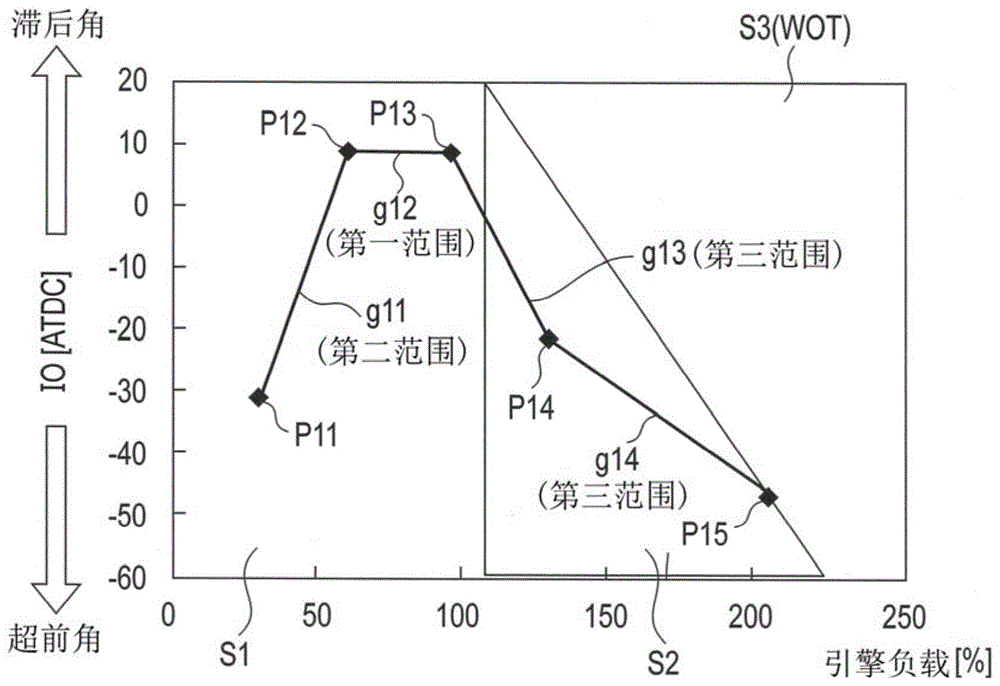
Hereinafter, the process of setting the target open timing of the intake valve 14 to be executed by the ECU50 is explained. Fig. 2 is a view showing an example in which the target open valve timing is to be set in accordance with the engine load. It should be noted that the setting of the target valve opening timing according to the engine load is stored in, for example, a storage device in the ECU 50.
In fig. 2, the horizontal axis represents the engine load (%), and the vertical axis represents the Intake Opening (IO) indicating the timing of opening the intake valve 14 After Top Dead Center (ATDC), i.e., after top dead center. It should be noted that, in the first embodiment, although the description is given by taking as an example the case where the horizontal axis represents the engine load of the engine 1, other characteristics of the engine 1 may be represented by the horizontal axis, for example, packing efficiency (packing efficiency) of the engine 1 may be represented by the horizontal axis.
With respect to the vertical axis, the higher the coordinate is, the larger the lag angle of the target open timing becomes, and the lower the coordinate is, the larger the lead angle of the target open timing becomes. The position at which the intake opening is zero is a position at which the intake valve 14 is closed at the same time at the top dead center timing, and the intake valve 14 is opened later as the target open timing approaches the retarded side, and the intake valve 14 is opened earlier as the target open timing approaches the advanced side.
The setting region of the target valve opening timing in fig. 2 is divided into a region S1 and a region S2 according to the engine load of the engine 1, the fuel consumption of the engine 1 is emphasized in the region S1, the output of the engine 1 is emphasized in the region S2, the region S2 includes a WOT region S3, and the supercharger 67 cannot supercharge the engine 1 in the WOT region S3. It should be noted that the region S3 included in the region 2 is a region where the mass of the intake air is small and the supercharger 67 cannot perform supercharging, so the control of setting the target open timing of the intake valve 14 is not performed. Hereinafter, the regions S1 and S2 will be described in more detail below.
In the region S1, the target open timing of the intake valve 14 is set for the purpose of improving the fuel consumption of the engine 1 by reducing pumping loss and preventing knocking.
The point P11 in the region S1 corresponds to a state where the engine load is about 30%. At point P11, the intake opening is made to have a lead angle of 30ATDC, whereby the overlap is set to such an extent that combustion in the combustion chamber 10 does not deteriorate, thereby reducing pumping loss. The point P12 in the region S1 corresponds to a state where the engine load is 50% to about 60%. The range from the point P11 to the point P12 is set such that the target opening timing of the intake valve 14 changes from the advanced angle side to the retarded angle side as the engine load increases, as indicated by the map g11 (second range).
At point P12, the intake opening is made to have a lag angle of about 10ATDC, thereby reducing the actual compression ratio inside the combustion chamber 10 and preventing knocking from occurring. It should be noted that point P12 is the start end of the knocking region (first range) in which the target valve opening timing is kept constant (see graph g 12). Therefore, when the point P12 is reached, the target open timing of the intake valve 14 is made not to have a larger retard angle, and is unchanged until the point P13 as shown in the graph g12 (first range).
Point P13 corresponds to a condition where the engine load is slightly less than 100%. Point P13 is the termination of the detonation region. The setting of the point P13 may be arbitrarily performed depending on the kind of the vehicle or the engine.
In the region S2, the required air amount specified by the driver is achieved, and the target open timing of the intake valve 14 for improving the output of the engine 1 is set, whereby the control of the air amount at the throttle valve or the exhaust valve and the setting of the target open timing of the intake valve 14 are correlated with each other, thereby achieving the improvement of the output of the engine 1.
The point P14 in the region S2 corresponds to a state where the engine load is approximately 120%. At the point P14, the required air amount specified by the driver is achieved, and an effort is made to achieve an improvement in the output of the engine 1, and the target opening timing of the intake valve 14 for improving fuel consumption is set while preventing occurrence of knocking by reducing the actual compression ratio in the combustion chamber 10. Therefore, the range from the aforementioned point P13 to the point P14 is set such that the target open timing of the intake valve 14 changes from the retarded angle side to the advanced angle side with an increase in engine load indicated by the map g13 (third range).
Point P15 corresponds to a condition where the engine load is approximately 200%. At point P15, the throttle valve is fully open, thereby achieving the maximum amount of air and improving output. The point P15 is set at the boundary between the region S2 and the region S3. The range from the point P14 to the point P15 is set such that the target open timing of the intake valve 14 changes from the retarded angle side to the advanced angle side with an increase in engine load as shown in the graph g14 (third range).
As described above, in the first embodiment, the configuration is designed such that the setting of the target open timing of the intake valve 14 indicated by the graphs g13 and g14 is performed on the left side of the boundary line between the region S2 and the region S3, that is, on the side of the region S1 where fuel consumption is emphasized, thereby further improving the fuel consumption of the engine 1.
Next, control of setting of the target open timing of the intake valve 14 of the engine 1 configured as described above will be described below. Fig. 3 is a flowchart showing an example of the process of setting the target open timing of the intake valve 14 to be executed by the ECU 50. This processing is performed while the engine 1 is operated.
As shown in fig. 3, the ECU50 calculates the engine load (ST 101). The ECU50 calculates the engine load based on, for example, the degree of opening of the throttle valve (throttle position). Then, the ECU50 sets the target opening timing of the intake valve 14 corresponding to the calculated engine load (ST 102: setting means). The ECU50 sets the target open timing of the intake valve 14 corresponding to the calculated engine load based on fig. 2, which has been described above.
Next, the ECU50 controls the variable valve timing mechanism 22 so as to control the opening/closing of the intake valve 14 so as to be able to achieve the set target valve opening timing (ST 103: variable valve timing control means). Then, the process moves to the return position.
Next, a comparison will be described below between a case where the setting of the target open timing of the intake valve 14 is performed in the same manner as in the first embodiment and a case where the setting of the target open timing of the intake valve 14 is performed in the same manner as in the conventional art based on whether the supercharger 67 is in the non-supercharging region or the supercharging region. Fig. 4 is a view showing an example of comparison between these cases. It should be noted that, in fig. 4, the vertical axis represents the engine load, and the horizontal axis represents the rotation speed of the engine 1.
Heretofore, whether the supercharger 67 is in the non-supercharged region or the supercharged region should be determined based on whether the supercharger 67 is in the 0-boost state. Accordingly, as shown in fig. 4, the non-supercharging region and the supercharging region are separated from each other with 0 boost as a criterion. Accordingly, when the target open timing of the intake valve 14 is to be set based on whether the supercharger is in the non-supercharging region or the supercharging region, the setting of the target open timing becomes coincident with the 0-boost.
However, in the first embodiment, the target open timing is set based on whether the fuel consumption of the engine 1 should be emphasized (region S1) or the output should be emphasized (region S2) as shown in the graph g, so that the target open timing of the intake valve 14 can be set regardless of whether the supercharging pressure of the supercharger 67 is in the non-supercharging region or the supercharging region.
As described above, the ECU50 can set the target open timing of the intake valve 14 regardless of whether the supercharging pressure of the supercharger 67 is in the non-supercharging pressure region or the supercharging pressure region. Therefore, when the engine 1 is operated at a low rotation speed with a low load, the ECU50 can cause the vehicle 100 to run with low fuel consumption even in the supercharging region. Further, the ECU50 sets the target opening timing of the intake valve 14 so as to move the setting from the boundary line between the region S2 and the region S3 toward the region S1 where fuel consumption is important (see the graphs g13 and g14 in fig. 2), so that the fuel consumption of the engine 1 can be further improved.
As described above, the ECU50 sets the target valve opening timing (first target valve opening timing) to be set when the load of the engine 1 is within the range (first range) from the point P12 to the point P13 later than both the target valve opening timing (second target valve opening timing) to be set when the load of the engine 1 is within the range (second range) from the point P11 to the point P12 and the target valve opening timing (third target valve opening timing) to be set when the load of the engine 1 is within the range (third range) from the point P13 to the point P15, the load in the second range is lower than the first range, and the load in the third range is higher than the first range, as shown in fig. 2. Therefore, in the first range, it is possible to reduce the actual compression ratio and prevent occurrence of knocking.
Further, as shown in the map g11, in the second range, the ECU50 sets the target valve opening timing (second target valve opening timing) such that the target valve opening timing (second target valve opening timing) becomes later as the load of the engine 1 increases.
As shown by the graphs g13, g14, in the third range, the ECU50 sets the target valve opening timing (third target valve opening timing) to be earlier as the load of the engine 1 increases.
Further, the third range includes a range of the load in which the supercharging is performed by the supercharger 67. Further, when the load is the maximum load in the third range, the ECU50 sets the target valve opening timing to a point P15 that is the latest timing among the valve opening timings at which the supercharge to be performed by the supercharger 67 can be achieved.
Further, in the second range, the ECU50 sets the valve opening timing of the intake valve 14 so as to provide a valve overlap period in which the exhaust valve 15 and the intake valve 14 are simultaneously in an open state.
Further, the first range is a range in which there is a load in which abnormal combustion of the engine 1 is likely to occur, and is set to be variable according to the rotation speed of the engine 1.
Further, as shown in the map g12, the ECU50 maintains the target valve opening timing (first target valve opening timing) to be set when the load of the engine 1 is within the first range at a constant valve opening timing.
As described above, the ECU50 can set an appropriate target valve opening timing according to the magnitude of the load on the engine 1.
(second embodiment)
The second embodiment differs from the first embodiment described above in that the target open timing of the intake valve 14 is set. Therefore, the setting of the target open timing of the intake valve 14 will be described in detail below. It should be noted that the same configurations as those of the first embodiment are denoted by the same reference numerals as those of the first embodiment, and detailed description thereof is omitted.
Fig. 5 is a view showing an example of setting the target open valve timing to be set according to the engine load according to the second embodiment. As shown in fig. 5, a range corresponding to the first range (hereinafter referred to as a first corresponding range) is formed within a range from a point P22 in the region S1 to P23 that is larger than the point P22 and is positioned at the boundary between the region S2 and the region S3.
When compared with the first embodiment, in the first embodiment, although the target valve opening timing of the intake valve 14 is set to move toward the fuel consumption-oriented region S1 side and to change from the retarded angle side to the advanced angle side with an increase in load when the first range passes (refer to graphs g13, g14 in fig. 2), in the second embodiment, when the first corresponding range passes, the target valve opening timing of the intake valve 14 is set to move to the side of the boundary between the output-oriented region S2 and the WOT region S3, more specifically, the target valve opening timing of the intake valve 14 is set to change from the retarded angle side to the advanced angle side with an increase in engine load from the point P23 to the point P24, and both the point P23 and the point P24 are positioned on the boundary line (refer to a graph g23 in fig. 5).
Also with the above configuration, the ECU50 can set the target open timing of the intake valve 14 regardless of whether the supercharging of the supercharger 67 is in the non-supercharging region or the supercharging region. Therefore, as in the first embodiment, when the engine 1 is operated at a low rotation speed with a low load, the ECU50 can cause the vehicle 100 to run with low fuel consumption even in the supercharging region.
It should be noted that in the engine 1, in a low load region such as an idle state or the like, in order to improve the starting performance, the target open timing of the intake valve 14 is set to the most retarded side, and as the load increases, the target open timing is gradually changed to the advanced side. Thereafter, the transition to the second range (the region where the load is lower than the knocking region) is completed, and then, as the load increases, the target valve opening timing is set closer to the retard side until the entry into the first range (the knocking region) is completed. Therefore, in the first or second embodiment described above, the ECU50 may set the target valve-opening timing (fourth target valve-opening timing) to be set when the load of the engine 1 is within a range (low load region: fourth range) lower than or equal to the point P11 or the target valve-opening timing to be set when the load of the engine 1 is within a range (low load region: fourth corresponding range) lower than or equal to the point P21 later than the first target valve-opening timing, the fourth range being a range in which the load is lower than the second range.
Additional advantages and modifications will readily appear to those skilled in the art. Therefore, the invention in its broader aspects is not limited to the specific details and representative embodiments shown and described herein. Accordingly, various modifications may be made without departing from the spirit or scope of the general inventive concept as defined by the appended claims and their equivalents.
Claims (9)
Applications Claiming Priority (2)
| Application Number | Priority Date | Filing Date | Title |
|---|---|---|---|
| JP2017-067823 | 2017-03-30 | ||
| JP2017067823A JP6930178B2 (en) | 2017-03-30 | 2017-03-30 | Internal combustion engine control device |
Publications (2)
| Publication Number | Publication Date |
|---|---|
| CN108691663A CN108691663A (en) | 2018-10-23 |
| CN108691663B true CN108691663B (en) | 2021-07-30 |
Family
ID=61731688
Family Applications (1)
| Application Number | Title | Priority Date | Filing Date |
|---|---|---|---|
| CN201810270452.XA Active CN108691663B (en) | 2017-03-30 | 2018-03-29 | Internal combustion engine controls |
Country Status (4)
| Country | Link |
|---|---|
| US (1) | US10550771B2 (en) |
| EP (1) | EP3382184B1 (en) |
| JP (1) | JP6930178B2 (en) |
| CN (1) | CN108691663B (en) |
Citations (4)
| Publication number | Priority date | Publication date | Assignee | Title |
|---|---|---|---|---|
| CN1550652A (en) * | 2003-05-15 | 2004-12-01 | �����Զ�����ʽ���� | Control devices for internal combustion engines |
| WO2007034308A3 (en) * | 2005-09-22 | 2007-10-04 | Toyota Motor Co Ltd | Boost pressure control apparatus and boost pressure control method of internal combustion engine |
| CN101573517A (en) * | 2006-12-21 | 2009-11-04 | 丰田自动车株式会社 | Control apparatus and control method for internal combustion engine |
| CN104471216A (en) * | 2012-07-25 | 2015-03-25 | 日产自动车株式会社 | Control device and control method of internal combustion engine |
Family Cites Families (9)
| Publication number | Priority date | Publication date | Assignee | Title |
|---|---|---|---|---|
| JP3325598B2 (en) * | 1992-04-13 | 2002-09-17 | マツダ株式会社 | Control device for engine with mechanical supercharger |
| JP3018892B2 (en) * | 1994-03-15 | 2000-03-13 | トヨタ自動車株式会社 | Valve timing control device for internal combustion engine |
| JP2001355462A (en) * | 2000-06-09 | 2001-12-26 | Denso Corp | Variable valve timing control device for internal combustion engine |
| DE10225305A1 (en) * | 2002-06-07 | 2003-12-18 | Bosch Gmbh Robert | Method and device for controlling an internal combustion engine |
| JP4066764B2 (en) * | 2002-09-30 | 2008-03-26 | 株式会社デンソー | Control device for internal combustion engine |
| JP4089408B2 (en) * | 2002-11-29 | 2008-05-28 | 三菱自動車工業株式会社 | High compression ratio cycle engine |
| JP2005090425A (en) * | 2003-09-19 | 2005-04-07 | Daihatsu Motor Co Ltd | Control method for internal combustion engine |
| US8375904B2 (en) * | 2010-02-18 | 2013-02-19 | Cummins Intellectual Property, Inc. | Early intake valve closing and variable valve timing assembly and method |
| JP5851463B2 (en) * | 2013-09-04 | 2016-02-03 | 本田技研工業株式会社 | Valve timing control device for internal combustion engine |
-
2017
- 2017-03-30 JP JP2017067823A patent/JP6930178B2/en active Active
-
2018
- 2018-03-21 EP EP18163086.4A patent/EP3382184B1/en active Active
- 2018-03-29 CN CN201810270452.XA patent/CN108691663B/en active Active
- 2018-03-29 US US15/940,594 patent/US10550771B2/en active Active
Patent Citations (4)
| Publication number | Priority date | Publication date | Assignee | Title |
|---|---|---|---|---|
| CN1550652A (en) * | 2003-05-15 | 2004-12-01 | �����Զ�����ʽ���� | Control devices for internal combustion engines |
| WO2007034308A3 (en) * | 2005-09-22 | 2007-10-04 | Toyota Motor Co Ltd | Boost pressure control apparatus and boost pressure control method of internal combustion engine |
| CN101573517A (en) * | 2006-12-21 | 2009-11-04 | 丰田自动车株式会社 | Control apparatus and control method for internal combustion engine |
| CN104471216A (en) * | 2012-07-25 | 2015-03-25 | 日产自动车株式会社 | Control device and control method of internal combustion engine |
Also Published As
| Publication number | Publication date |
|---|---|
| EP3382184B1 (en) | 2021-05-19 |
| CN108691663A (en) | 2018-10-23 |
| US10550771B2 (en) | 2020-02-04 |
| EP3382184A1 (en) | 2018-10-03 |
| JP6930178B2 (en) | 2021-09-01 |
| US20180283290A1 (en) | 2018-10-04 |
| JP2018168788A (en) | 2018-11-01 |
Similar Documents
| Publication | Publication Date | Title |
|---|---|---|
| JP7121332B2 (en) | Control device for internal combustion engine | |
| CN108884804B (en) | Control device for internal combustion engine | |
| US10060361B2 (en) | Method for performing a charge exchange in an internal combustion engine | |
| JP4666162B2 (en) | Fuel injection control device for internal combustion engine | |
| JP2013130121A (en) | Exhaust gas recirculation system for spark-ignition-type internal combustion engine | |
| JP5206906B2 (en) | Control device for internal combustion engine | |
| JP6090641B2 (en) | Control device for internal combustion engine | |
| CN108691663B (en) | Internal combustion engine controls | |
| JP5338709B2 (en) | Control device for internal combustion engine | |
| JP2019135386A (en) | Internal combustion engine | |
| JP5472481B2 (en) | Engine control device | |
| CN107664072A (en) | The control device of internal combustion engine | |
| JP7256682B2 (en) | Internal combustion engine control method and internal combustion engine control device | |
| JP7722309B2 (en) | Ignition timing control device for internal combustion engine | |
| CN110360013A (en) | engine control equipment | |
| JP5594265B2 (en) | Engine intake control device | |
| US10598106B2 (en) | Control device for internal combustion engine and control method for internal combustion engine | |
| JP5888604B2 (en) | Control device for internal combustion engine | |
| JP2024051959A (en) | Ignition timing control device for internal combustion engine | |
| JP2010019085A (en) | Intake control device for engine | |
| JP2006283654A (en) | Internal combustion engine | |
| JP2006283653A (en) | Intake control device | |
| WO2017150077A1 (en) | Engine control device | |
| JP2013072372A (en) | Control device of internal combustion engine |
Legal Events
| Date | Code | Title | Description |
|---|---|---|---|
| PB01 | Publication | ||
| PB01 | Publication | ||
| SE01 | Entry into force of request for substantive examination | ||
| SE01 | Entry into force of request for substantive examination | ||
| GR01 | Patent grant | ||
| GR01 | Patent grant |