CN108660552B - A shock-absorbing base for textile equipment - Google Patents
A shock-absorbing base for textile equipment Download PDFInfo
- Publication number
- CN108660552B CN108660552B CN201810422685.7A CN201810422685A CN108660552B CN 108660552 B CN108660552 B CN 108660552B CN 201810422685 A CN201810422685 A CN 201810422685A CN 108660552 B CN108660552 B CN 108660552B
- Authority
- CN
- China
- Prior art keywords
- fixedly connected
- plate
- textile equipment
- far away
- groove
- Prior art date
- Legal status (The legal status is an assumption and is not a legal conclusion. Google has not performed a legal analysis and makes no representation as to the accuracy of the status listed.)
- Active
Links
Images


Classifications
-
- D—TEXTILES; PAPER
- D01—NATURAL OR MAN-MADE THREADS OR FIBRES; SPINNING
- D01H—SPINNING OR TWISTING
- D01H1/00—Spinning or twisting machines in which the product is wound-up continuously
- D01H1/14—Details
- D01H1/16—Framework; Casings; Coverings ; Removal of heat; Means for generating overpressure of air against infiltration of dust; Ducts for electric cables
-
- D—TEXTILES; PAPER
- D03—WEAVING
- D03D—WOVEN FABRICS; METHODS OF WEAVING; LOOMS
- D03D49/00—Details or constructional features not specially adapted for looms of a particular type
- D03D49/02—Construction of loom framework
- D03D49/025—Ground supports
Landscapes
- Engineering & Computer Science (AREA)
- Textile Engineering (AREA)
- Mechanical Engineering (AREA)
- Looms (AREA)
- Vibration Prevention Devices (AREA)
Abstract
本发明公开了一种纺织设备用减震底座,包括底板,所述底板上表面的中部固定连接有固定块,固定块的上表面开设有两个相对称的凹槽,每个凹槽的内部均固定连接有滑杆,每个滑杆的外表面均套设有与滑杆相适配的滑环,每个滑环上表面的中部均固定连接有支撑块。该纺织设备用减震底座,更好的在纺织设备本体运行震动的时候压动连接板进行晃动,更好的通过第四强力弹簧的弹力对产生的震动进行缓冲减震,能够更好的通过产生震动的时候压动第一强力弹簧进行收缩,提高了该装置的减震效果,能够更好的在纺织设备本体运行的过程中通过第二强力弹簧的弹力压动压板对纺织设备本体的位置进行限制,避免在使用的过程中造成滑动脱落的问题。
The invention discloses a shock absorbing base for textile equipment, comprising a bottom plate, a middle part of the upper surface of the bottom plate is fixedly connected with a fixing block, and two symmetrical grooves are opened on the upper surface of the fixing block, and the inner part of each groove is A sliding rod is fixedly connected with each sliding rod, a sliding ring matching with the sliding rod is sleeved on the outer surface of each sliding rod, and a support block is fixedly connected to the middle part of the upper surface of each sliding ring. The textile equipment uses a shock-absorbing base, which can better press the connecting plate to shake when the textile equipment body vibrates. When the vibration occurs, the first strong spring is pressed to contract, which improves the shock absorption effect of the device, and can better press the pressure plate to the position of the textile equipment body through the elastic force of the second strong spring during the operation of the textile equipment body. Limit it to avoid the problem of sliding and falling off during use.
Description
技术领域technical field
本发明涉及纺织技术领域,具体为一种纺织设备用减震底座。The invention relates to the technical field of textiles, in particular to a shock-absorbing base for textile equipment.
背景技术Background technique
纺织是取自纺纱与织布的总称,但是随着纺织知识体系和学科体系的不断发展和完善,特别是非织造纺织材料和三维复合编织等技术产生后,纺织不仅是传统的纺纱和织布,也包括无纺布技术,三维编织技术,静电纳米成网技术等,纺织大致分为纺纱与编织两道工序,在纺织设备进行纺织的过程中,设备会产生震动,这时就需要一种减震底座来进行减震限位。Textile is a general term derived from spinning and weaving, but with the continuous development and improvement of the textile knowledge system and discipline system, especially after the emergence of technologies such as non-woven textile materials and three-dimensional composite weaving, textile is not only traditional spinning and weaving. Cloth, including non-woven technology, three-dimensional weaving technology, electrostatic nano-netting technology, etc., textiles are roughly divided into two processes: spinning and weaving. A shock-absorbing base for shock-absorbing limit.
现有的纺织设备用减震底座在使用的过程中,容易造成纺织设备在运行的时候振动造成移动,减震效果不好,严重影响了设备的使用效果,为此,我们提出了一种纺织设备用减震底座,来解决这一问题。In the process of using the existing shock-absorbing base for textile equipment, it is easy to cause the textile equipment to vibrate and move during operation, and the shock absorption effect is not good, which seriously affects the use effect of the equipment. Therefore, we propose a textile equipment. The equipment uses a shock-absorbing base to solve this problem.
发明内容SUMMARY OF THE INVENTION
(一)解决的技术问题(1) Technical problems solved
针对现有技术的不足,本发明提供了一种纺织设备用减震底座,解决了现有的纺织设备用减震底座减震效果不好的问题。In view of the deficiencies of the prior art, the present invention provides a shock-absorbing base for textile equipment, which solves the problem of poor shock-absorbing effect of the existing shock-absorbing base for textile equipment.
(二)技术方案(2) Technical solutions
为实现上述目的,本发明提供如下技术方案:一种纺织设备用减震底座,包括底板,所述底板上表面的中部固定连接有固定块,所述固定块的上表面开设有两个相对称的凹槽,每个所述凹槽的内部均固定连接有滑杆,每个所述滑杆的外表面均套设有与滑杆相适配的滑环,每个所述滑环上表面的中部均固定连接有支撑块,所述固定板的上方放置有连接板,所述连接板的底面开设有空槽,所述空槽内顶壁的中部固定连接有固定板,所述固定板的左右两端均通过第一销钉固定铰接有连接杆,每个所述连接杆远离固定板的一端均通过第二销钉与支撑块固定铰接,所述连接板的内部开设有两个相对称的空腔,且空槽位于两个空腔之间,每个所述空腔的内部均放置有移动板,每个所述移动板的上表面均固定连接有第一强力弹簧,每个所述第一强力弹簧远离移动板的一侧面均与空腔的内顶壁固定连接,所述连接板的底面固定镶嵌有两个相对称的限位管,且限位管与空腔相连通,每个所述移动板底面的中部均固定连接有竖杆,所述连接板的上表面放置有纺织设备本体,所述底板的上表面固定连接有两个相对称的侧板,两个所述侧板相互靠近一侧面的上部均开设有限位槽,每个所述限位槽的内侧壁均固定连接有第二强力弹簧,所述纺织设备本体的左右两侧均放置有挤压板,两个所述挤压板相互靠近的一侧面分别与纺织设备本体左右两侧面的下部相接触,两个所述挤压板相互远离的一侧面分别与两个第二强力弹簧相互靠近的一端固定连接,两个所述挤压板相互远离一侧面的中部均固定连接有限位杆,两个所述侧板相互远离一侧面的上部均固定镶嵌有连接管,两个所述限位杆相互远离的一端均贯穿连接管并延伸至侧板的外侧。In order to achieve the above purpose, the present invention provides the following technical solutions: a shock-absorbing base for textile equipment, comprising a bottom plate, a middle part of the upper surface of the bottom plate is fixedly connected with a fixed block, and the upper surface of the fixed block is provided with two symmetrical Each of the grooves is fixedly connected with a sliding rod, the outer surface of each sliding rod is sleeved with a sliding ring that is adapted to the sliding rod, and the upper surface of each sliding ring is A support block is fixedly connected to the middle part of the hollow groove, a connecting plate is placed above the fixed plate, an empty groove is opened on the bottom surface of the connecting plate, and a fixed plate is fixedly connected to the middle of the top wall of the hollow groove. The left and right ends of the connecting rod are fixed and hinged with connecting rods through the first pin, and the end of each connecting rod away from the fixed plate is fixed and hinged with the support block through the second pin, and the interior of the connecting board is provided with two symmetrical a cavity, and the hollow slot is located between the two cavities, a moving plate is placed inside each of the cavities, a first strong spring is fixedly connected to the upper surface of each of the moving plates, and each of the One side of the first strong spring away from the moving plate is fixedly connected with the inner top wall of the cavity, the bottom surface of the connecting plate is fixedly inlaid with two symmetrical limit tubes, and the limit tubes are communicated with the cavity. Vertical rods are fixedly connected to the middle of the bottom surface of each of the moving plates, the upper surface of the connecting plate is placed with a textile equipment body, and the upper surface of the bottom plate is fixedly connected with two symmetrical side plates. The upper part of one side of the plates close to each other is provided with limit grooves, the inner side wall of each limit groove is fixedly connected with a second strong spring, the left and right sides of the textile equipment body are placed with extruded plates, two One side of the pressing plates that is close to each other is in contact with the lower parts of the left and right sides of the textile equipment body, and one side of the two pressing plates that is far away from each other is fixedly connected to the ends of the two second strong springs that are close to each other, respectively. The middle parts of the two extruded plates away from each other on one side are fixedly connected with limit rods, the upper parts of the two side plates away from each other on one side are fixedly inlaid with connecting pipes, and the ends of the two limit rods away from each other They all pass through the connecting pipe and extend to the outside of the side plate.
优选的,两个所述凹槽相互远离的内侧壁均固定连接有第三强力弹簧,两个所述第三强力弹簧相互靠近的一侧面分别与两个滑环相互远离的一侧面固定连接,且第三强力弹簧与滑杆相套接。Preferably, the inner side walls of the two grooves that are far away from each other are fixedly connected with a third strong spring, and one side of the two third strong springs that are close to each other is fixedly connected to one side of the two slip rings that are far away from each other, respectively, And the third strong spring is sleeved with the sliding rod.
优选的,每个所述竖杆远离移动板的一端均贯穿限位管并延伸至连接板的下方,每个所述竖杆远离移动板的一侧面均与底板的上表面固定连接。Preferably, one end of each vertical rod away from the moving plate penetrates the limiting tube and extends below the connecting plate, and one side of each vertical rod away from the moving plate is fixedly connected to the upper surface of the bottom plate.
优选的,两个所述侧板相互远离的一侧均放置有限制块,两个所述限位杆相互远离的一侧面分别与两个限制块相互靠近的一侧面固定连接。Preferably, a limit block is placed on one side of the two side plates that are far away from each other, and one side of the two limit bars that are far away from each other is fixedly connected to one side of the two limit blocks that are close to each other.
优选的,所述固定块的水平长度值小于空槽的水平长度值,所述滑环的底面与凹槽的内底壁之间留有间隙。Preferably, the horizontal length value of the fixing block is smaller than the horizontal length value of the hollow groove, and a gap is left between the bottom surface of the slip ring and the inner bottom wall of the groove.
优选的,所述固定板底面的中部固定连接第四强力弹簧,所述第四强力弹簧远离固定板的一侧面与固定块上表面的中部固定连接。Preferably, the middle part of the bottom surface of the fixing plate is fixedly connected with a fourth strong spring, and a side surface of the fourth strong spring away from the fixing plate is fixedly connected with the middle part of the upper surface of the fixing block.
(三)有益效果(3) Beneficial effects
本发明提供了一种纺织设备用减震底座,具备以下有益效果:The invention provides a shock-absorbing base for textile equipment, which has the following beneficial effects:
(1)该纺织设备用减震底座,通过设置有底板,配合使用固定板、固定板、第一销钉、连接杆、凹槽、滑杆、滑环、第三强力弹簧、支撑块和第二销钉,能够更好的在纺织设备本体运行震动的时候压动连接板进行晃动,从而通过固定板压动两个滑环进行滑动,从而通过第三强力弹簧的弹力对产生的震动力进行缓冲,从而起到减震的效果,通过设置有固定板和第四强力弹簧,能够更好的通过第四强力弹簧的弹力对产生的震动进行缓冲减震。(1) The shock-absorbing base for the textile equipment is provided with a bottom plate, and is matched with a fixed plate, a fixed plate, a first pin, a connecting rod, a groove, a sliding rod, a sliding ring, a third strong spring, a support block and a second The pin can better press the connecting plate to shake when the textile equipment body vibrates, so as to press the two slip rings to slide through the fixed plate, so as to buffer the generated vibration force by the elastic force of the third strong spring. Thereby, the effect of shock absorption is achieved. By providing the fixed plate and the fourth strong spring, the generated vibration can be better buffered and damped by the elastic force of the fourth strong spring.
(2)该纺织设备用减震底座,通过设置有连接板,配合使用空腔、第一强力弹簧、移动板、限位管和竖杆,能够更好的通过产生震动的时候压动第一强力弹簧进行收缩,从而通过第一强力弹簧的弹力进行减震处理,提高了该装置的减震效果,通过设置有底板,配合使用侧板、第二强力弹簧、限位槽、限位杆、连接管和限制板,能够更好的在纺织设备本体运行的过程中通过第二强力弹簧的弹力压动压板对纺织设备本体的位置进行限制,避免在使用的过程中造成滑动脱落的问题。(2) The shock-absorbing base for the textile equipment is provided with a connecting plate, and the cavity, the first strong spring, the moving plate, the limit tube and the vertical rod can be used together to better press the first vibration when the vibration is generated. The strong spring shrinks, so that the shock absorption treatment is performed by the elastic force of the first strong spring, and the shock absorption effect of the device is improved. The connecting pipe and the limiting plate can better limit the position of the textile equipment body by the elastic pressing plate of the second strong spring during the operation of the textile equipment body, so as to avoid the problem of sliding and falling off during use.
附图说明Description of drawings
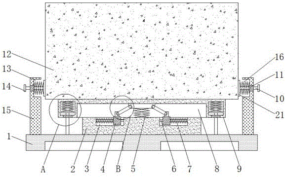
图1为本发明固定块正视图的剖视图;Fig. 1 is the sectional view of the front view of the fixed block of the present invention;
图2为本发明图1中A处结构放大示意图;Fig. 2 is the enlarged schematic diagram of the structure at place A in Fig. 1 of the present invention;
图3为本发明图1中B处结构放大示意图。FIG. 3 is an enlarged schematic view of the structure at B in FIG. 1 of the present invention.
图中:1底板、2固定块、3凹槽、4滑环、5第四强力弹簧、6滑杆、7第三强力弹簧、8空槽、9连接板、10限位杆、11连接管、12纺织设备本体、13限位槽、14限制块、15侧板、16第二强力弹簧、17竖杆、18限位管、19移动板、20第一强力弹簧、21压板、22空腔、23支撑块、24第二销钉、25连接杆、26第一销钉、27固定板。In the picture: 1 bottom plate, 2 fixed block, 3 groove, 4 slip ring, 5 fourth strong spring, 6 sliding rod, 7 third strong spring, 8 empty groove, 9 connecting plate, 10 limit rod, 11 connecting pipe , 12 textile equipment body, 13 limit slot, 14 limit block, 15 side plate, 16 second strong spring, 17 vertical rod, 18 limit tube, 19 moving plate, 20 first strong spring, 21 pressure plate, 22 cavity , 23 supporting block, 24 second pin, 25 connecting rod, 26 first pin, 27 fixing plate.
具体实施方式Detailed ways
下面将结合本发明实施例中的附图,对本发明实施例中的技术方案进行清楚、完整地描述,显然,所描述的实施例仅仅是本发明一部分实施例,而不是全部的实施例。基于本发明中的实施例,本领域普通技术人员在没有做出创造性劳动前提下所获得的所有其他实施例,都属于本发明保护的范围。The technical solutions in the embodiments of the present invention will be clearly and completely described below with reference to the accompanying drawings in the embodiments of the present invention. Obviously, the described embodiments are only a part of the embodiments of the present invention, but not all of the embodiments. Based on the embodiments of the present invention, all other embodiments obtained by those of ordinary skill in the art without creative efforts shall fall within the protection scope of the present invention.
请参阅图1-3,本发明提供一种技术方案:一种纺织设备用减震底座,包括底板1,底板1上表面的中部固定连接有固定块2,固定块2的上表面开设有两个相对称的凹槽3,每个凹槽3的内部均固定连接有滑杆6,每个滑杆6的外表面均套设有与滑杆6相适配的滑环4,两个凹槽3相互远离的内侧壁均固定连接有第三强力弹簧7,两个第三强力弹簧7相互靠近的一侧面分别与两个滑环4相互远离的一侧面固定连接,且第三强力弹簧7与滑杆6相套接,能够更好的通过第三强力弹簧7的弹力对震动进行缓冲,每个滑环4上表面的中部均固定连接有支撑块23,固定板2的上方放置有连接板9,连接板9的底面开设有空槽8,固定块2的水平长度值小于空槽8的水平长度值,滑环4的底面与凹槽3的内底壁之间留有间隙,能够更好的避免在进行减震的时候造成摩擦卡顿的问题,空槽8内顶壁的中部固定连接有固定板27,固定板27底面的中部固定连接第四强力弹簧5,第四强力弹簧5远离固定板27的一侧面与固定块2上表面的中部固定连接,能够更好的通过第四强力弹簧5的弹力对震动力进行缓冲减震,提高了该装置的减震效果,固定板27的左右两端均通过第一销钉26固定铰接有连接杆25,每个连接杆25远离固定板27的一端均通过第二销钉24与支撑块23固定铰接,连接板9的内部开设有两个相对称的空腔22,且空槽8位于两个空腔22之间,每个空腔22的内部均放置有移动板19,每个移动板19的上表面均固定连接有第一强力弹簧20,每个第一强力弹簧20远离移动板19的一侧面均与空腔22的内顶壁固定连接,连接板9的底面固定镶嵌有两个相对称的限位管18,且限位管18与空腔22相连通,每个移动板19底面的中部均固定连接有竖杆17,每个竖杆17远离移动板19的一端均贯穿限位管18并延伸至连接板9的下方,每个竖杆17远离移动板19的一侧面均与底板1的上表面固定连接,能够更好的在震动的时候移动板19压动第一强力弹簧20进行收缩,从而通过第一强力弹簧20的弹力对震动进行缓冲减震,连接板9的上表面放置有纺织设备本体12,底板1的上表面固定连接有两个相对称的侧板15,两个侧板15相互靠近一侧面的上部均开设有限位槽13,每个限位槽13的内侧壁均固定连接有第二强力弹簧16,纺织设备本体12的左右两侧均放置有挤压板21,两个挤压板21相互靠近的一侧面分别与纺织设备本体12左右两侧面的下部相接触,两个挤压板21相互远离的一侧面分别与两个第二强力弹簧16相互靠近的一端固定连接,两个挤压板21相互远离一侧面的中部均固定连接有限位杆10,两个侧板15相互远离一侧面的上部均固定镶嵌有连接管11,两个限位杆10相互远离的一端均贯穿连接管11并延伸至侧板15的外侧,两个侧板15相互远离的一侧均放置有限制块14,两个限位杆10相互远离的一侧面分别与两个限制块14相互靠近的一侧面固定连接,能够更好的通过对限位杆10的位置进行限制,避免在使用的过程中造成脱落的问题。1-3, the present invention provides a technical solution: a shock-absorbing base for textile equipment, comprising a
工作原理:将纺织设备本体12放置在连接板9上,通过两个第二强力弹簧16的弹力压动压板21向内侧进行移动,从而对纺织设备本体12进行夹持稳固,在纺织设备本体12运行的过程中,产生的振动压动连接板9进行振动,从而压动两个滑环4进行滑动,并通过两个第三强力弹簧7和第四强力弹簧5对振动进行缓冲减震,在连接板9进行震动移动的过程中,移动板19压动第一强力弹簧20进行收缩,从而通过第一强力弹簧20的弹力对振动进行缓冲处理,从而达到了减震的效果。Working principle: The
综上所述,该纺织设备用减震底座,通过设置有底板1,配合使用固定板2、固定板27、第一销钉26、连接杆25、凹槽3、滑杆6、滑环4、第三强力弹簧7、支撑块23和第二销钉24,能够更好的在纺织设备本体12运行震动的时候压动连接板9进行晃动,从而通过固定板27压动两个滑环4进行滑动,从而通过第三强力弹簧7的弹力对产生的震动力进行缓冲,从而起到减震的效果,通过设置有固定板27和第四强力弹簧5,能够更好的通过第四强力弹簧5的弹力对产生的震动进行缓冲减震,通过设置有连接板9,配合使用空腔22、第一强力弹簧20、移动板19、限位管18和竖杆17,能够更好的通过产生震动的时候压动第一强力弹簧20进行收缩,从而通过第一强力弹簧20的弹力进行减震处理,提高了该装置的减震效果,通过设置有底板1,配合使用侧板15、第二强力弹簧16、限位槽13、限位杆10、连接管11和限制板14,能够更好的在纺织设备本体12运行的过程中通过第二强力弹簧16的弹力压动压板21对纺织设备本体12的位置进行限制,避免在使用的过程中造成滑动脱落的问题。In summary, the shock-absorbing base for textile equipment is provided with a
需要说明的是,在本文中,诸如第一和第二等之类的关系术语仅仅用来将一个实体或者操作与另一个实体或操作区分开来,而不一定要求或者暗示这些实体或操作之间存在任何这种实际的关系或者顺序。It should be noted that, in this document, relational terms such as first and second are only used to distinguish one entity or operation from another entity or operation, and do not necessarily require or imply any relationship between these entities or operations. any such actual relationship or sequence exists.
尽管已经示出和描述了本发明的实施例,对于本领域的普通技术人员而言,可以理解在不脱离本发明的原理和精神的情况下可以对这些实施例进行多种变化、修改、替换和变型,本发明的范围由所附权利要求及其等同物限定。Although embodiments of the present invention have been shown and described, it will be understood by those skilled in the art that various changes, modifications, and substitutions can be made in these embodiments without departing from the principle and spirit of the invention and modifications, the scope of the present invention is defined by the appended claims and their equivalents.
Claims (5)
Priority Applications (1)
| Application Number | Priority Date | Filing Date | Title |
|---|---|---|---|
| CN201810422685.7A CN108660552B (en) | 2018-05-05 | 2018-05-05 | A shock-absorbing base for textile equipment |
Applications Claiming Priority (1)
| Application Number | Priority Date | Filing Date | Title |
|---|---|---|---|
| CN201810422685.7A CN108660552B (en) | 2018-05-05 | 2018-05-05 | A shock-absorbing base for textile equipment |
Publications (2)
| Publication Number | Publication Date |
|---|---|
| CN108660552A CN108660552A (en) | 2018-10-16 |
| CN108660552B true CN108660552B (en) | 2020-10-27 |
Family
ID=63778001
Family Applications (1)
| Application Number | Title | Priority Date | Filing Date |
|---|---|---|---|
| CN201810422685.7A Active CN108660552B (en) | 2018-05-05 | 2018-05-05 | A shock-absorbing base for textile equipment |
Country Status (1)
| Country | Link |
|---|---|
| CN (1) | CN108660552B (en) |
Families Citing this family (6)
| Publication number | Priority date | Publication date | Assignee | Title |
|---|---|---|---|---|
| CN109487419A (en) * | 2018-11-19 | 2019-03-19 | 安徽好莱克纺织科技有限公司 | A kind of loom damping device |
| CN110863272A (en) * | 2019-11-29 | 2020-03-06 | 安徽翰联色纺股份有限公司 | Textile machine for yarn production and processing |
| CN112097063A (en) * | 2020-09-18 | 2020-12-18 | 浙江笑谈科技有限公司 | A can accomodate foldable spinning rack for weaving machine |
| CN111879956B (en) * | 2020-09-25 | 2021-01-05 | 东营市宇彤机电设备有限责任公司 | Anti-seismic accelerometer |
| CN112456221A (en) * | 2020-11-26 | 2021-03-09 | 江西锦囊商旅信息有限公司 | Shock attenuation weaving equipment pay-off |
| CN113783126B (en) * | 2021-11-11 | 2022-02-08 | 江苏天翔电气有限公司 | Regulator cubicle base with shock-absorbing function |
Citations (9)
| Publication number | Priority date | Publication date | Assignee | Title |
|---|---|---|---|---|
| US5038835A (en) * | 1989-01-12 | 1991-08-13 | Lindauer Dornier Gesellschaft Mbh | Apparatus for isolating loom vibrations and continuously adjusting its level |
| JP2004332847A (en) * | 2003-05-08 | 2004-11-25 | Yaskawa Electric Corp | Damping device |
| JP4353341B2 (en) * | 1999-09-03 | 2009-10-28 | 株式会社昭電 | Seismic isolation device |
| CN105570625A (en) * | 2016-03-08 | 2016-05-11 | 苏州市的卢纺织有限公司 | Textile machine supporting frame with shock absorption function |
| CN105862234A (en) * | 2016-06-01 | 2016-08-17 | 江苏金铁人自动化科技有限公司 | Rack damping device |
| CN106438833A (en) * | 2016-08-24 | 2017-02-22 | 无锡科通工程机械制造有限公司 | Adjustable buffer device |
| CN106989135A (en) * | 2017-05-23 | 2017-07-28 | 江苏好运鸽机械有限公司 | A kind of loom framework damping device |
| CN106989136A (en) * | 2017-06-05 | 2017-07-28 | 长江师范学院 | Shock-absorbing device for mechanical equipment |
| JP6274172B2 (en) * | 2015-09-01 | 2018-02-07 | 大亦 絢一郎 | Seismic isolation table device |
-
2018
- 2018-05-05 CN CN201810422685.7A patent/CN108660552B/en active Active
Patent Citations (9)
| Publication number | Priority date | Publication date | Assignee | Title |
|---|---|---|---|---|
| US5038835A (en) * | 1989-01-12 | 1991-08-13 | Lindauer Dornier Gesellschaft Mbh | Apparatus for isolating loom vibrations and continuously adjusting its level |
| JP4353341B2 (en) * | 1999-09-03 | 2009-10-28 | 株式会社昭電 | Seismic isolation device |
| JP2004332847A (en) * | 2003-05-08 | 2004-11-25 | Yaskawa Electric Corp | Damping device |
| JP6274172B2 (en) * | 2015-09-01 | 2018-02-07 | 大亦 絢一郎 | Seismic isolation table device |
| CN105570625A (en) * | 2016-03-08 | 2016-05-11 | 苏州市的卢纺织有限公司 | Textile machine supporting frame with shock absorption function |
| CN105862234A (en) * | 2016-06-01 | 2016-08-17 | 江苏金铁人自动化科技有限公司 | Rack damping device |
| CN106438833A (en) * | 2016-08-24 | 2017-02-22 | 无锡科通工程机械制造有限公司 | Adjustable buffer device |
| CN106989135A (en) * | 2017-05-23 | 2017-07-28 | 江苏好运鸽机械有限公司 | A kind of loom framework damping device |
| CN106989136A (en) * | 2017-06-05 | 2017-07-28 | 长江师范学院 | Shock-absorbing device for mechanical equipment |
Also Published As
| Publication number | Publication date |
|---|---|
| CN108660552A (en) | 2018-10-16 |
Similar Documents
| Publication | Publication Date | Title |
|---|---|---|
| CN108660552B (en) | A shock-absorbing base for textile equipment | |
| CN207739022U (en) | A kind of flatiron textile fabric processing unit (plant) | |
| CN108842603A (en) | A kind of high-damping rubber shock-absorbing bridge support | |
| CN211917693U (en) | Pneumatic bending device of flexible circuit board for wearable equipment | |
| CN210969958U (en) | High 3D printer of stability | |
| CN108839940B (en) | Mounting fixing frame for electromechanical equipment | |
| CN115653221A (en) | Wallboard dry hanging structure | |
| CN107641934A (en) | A kind of washing machine shock-absorbing suspension rod | |
| CN210106480U (en) | Shock absorption mechanism for rotary rolling machine | |
| CN108032779A (en) | An embedded car refrigerator structure and its application method | |
| CN214493892U (en) | Dyeing kit | |
| CN209348175U (en) | A chromatographic column packing device for purification of traditional Chinese medicine | |
| CN206070166U (en) | A kind of sweat shirt cloth immersion contraction framework | |
| CN110820092B (en) | A textile machine with shock absorption | |
| CN209579125U (en) | A kind of fixed device of sprocket wheel processing | |
| CN210484508U (en) | Vibration/noise reduction system of printing roller production process | |
| CN210409837U (en) | Automatic dust fall environment-friendly device in field area | |
| CN106197991A (en) | A kind of spring part stretching device repeatedly | |
| CN208026530U (en) | An orifice plate suitable for sample pretreatment in pharmaceutical analysis | |
| CN115163738A (en) | Electric welding machine with shock absorption function and shock absorption method thereof | |
| CN216843663U (en) | Effectual antidetonation gallows for water supply and drainage pipeline of shock attenuation | |
| CN208273177U (en) | A kind of concert sound equipment damping device | |
| CN209039850U (en) | Vacuum tattoo machine is used in a kind of production of synthetic leather | |
| CN213566058U (en) | A concrete test block curing and handling device | |
| CN210868160U (en) | Be applied to speaker of intelligence fingerprint pronunciation pickproof lock |
Legal Events
| Date | Code | Title | Description |
|---|---|---|---|
| PB01 | Publication | ||
| PB01 | Publication | ||
| SE01 | Entry into force of request for substantive examination | ||
| SE01 | Entry into force of request for substantive examination | ||
| TA01 | Transfer of patent application right |
Effective date of registration: 20200928 Address after: 223900 No.1, Jinshajiang East Road, Sihong County, Suqian City, Jiangsu Province Applicant after: Jiangsu Suwan Pharmaceutical Technology Co.,Ltd. Address before: Wang Industrial Park off the road 235000 Anhui city of Huaibei province Pang Duji District No. 7 Applicant before: Li Peipei |
|
| TA01 | Transfer of patent application right | ||
| GR01 | Patent grant | ||
| GR01 | Patent grant | ||
| TR01 | Transfer of patent right |
Effective date of registration: 20220316 Address after: 223900 No. 1, Xingsheng Road, Changshu Sihong Industrial Park, Sihong County, Suqian City, Jiangsu Province Patentee after: Jiangsu Xunding New Material Technology Co.,Ltd. Address before: 223900 No.1 Jinshajiang East Road, Sihong County, Suqian City, Jiangsu Province Patentee before: Jiangsu Suwan Pharmaceutical Technology Co.,Ltd. |
|
| TR01 | Transfer of patent right | ||
| TR01 | Transfer of patent right |
Effective date of registration: 20250214 Address after: No. 80 Xingye Road, Suihe Street, Suining County, Xuzhou City, Jiangsu Province, China 221299 Patentee after: Jiangsu Ruiyusheng New Material Technology Co.,Ltd. Country or region after: China Address before: 223900 No. 1, Xingsheng Road, Changshu Sihong Industrial Park, Sihong County, Suqian City, Jiangsu Province Patentee before: Jiangsu Xunding New Material Technology Co.,Ltd. Country or region before: China |
|
| TR01 | Transfer of patent right | ||
| TR01 | Transfer of patent right |
Effective date of registration: 20250924 Address after: 223900 No. 1, Xingsheng Road, Changshu Sihong Industrial Park, Sihong County, Suqian City, Jiangsu Province Patentee after: Jiangsu Xunding New Material Technology Co.,Ltd. Country or region after: China Address before: No. 80 Xingye Road, Suihe Street, Suining County, Xuzhou City, Jiangsu Province, China 221299 Patentee before: Jiangsu Ruiyusheng New Material Technology Co.,Ltd. Country or region before: China |
|
| TR01 | Transfer of patent right | ||
| CP03 | Change of name, title or address |
Address after: 221000 Jiangsu Province XuZhou City Suining County Suhetang Street Xingye Road No. 80 Jiangsu Ruidecheng New Material Technology Co., Ltd. yard comprehensive building 1-103 room Patentee after: Jiangsu Xunding New Material Technology Co.,Ltd. Country or region after: China Address before: 223900 No. 1, Xingsheng Road, Changshu Sihong Industrial Park, Sihong County, Suqian City, Jiangsu Province Patentee before: Jiangsu Xunding New Material Technology Co.,Ltd. Country or region before: China |
|
| CP03 | Change of name, title or address |