CN108645376B - Telescopic leveling device and detection method thereof - Google Patents
Telescopic leveling device and detection method thereof Download PDFInfo
- Publication number
- CN108645376B CN108645376B CN201810580815.XA CN201810580815A CN108645376B CN 108645376 B CN108645376 B CN 108645376B CN 201810580815 A CN201810580815 A CN 201810580815A CN 108645376 B CN108645376 B CN 108645376B
- Authority
- CN
- China
- Prior art keywords
- cable
- centering rod
- sag
- level
- leveling device
- Prior art date
- Legal status (The legal status is an assumption and is not a legal conclusion. Google has not performed a legal analysis and makes no representation as to the accuracy of the status listed.)
- Active
Links
Images


Classifications
-
- G—PHYSICS
- G01—MEASURING; TESTING
- G01C—MEASURING DISTANCES, LEVELS OR BEARINGS; SURVEYING; NAVIGATION; GYROSCOPIC INSTRUMENTS; PHOTOGRAMMETRY OR VIDEOGRAMMETRY
- G01C5/00—Measuring height; Measuring distances transverse to line of sight; Levelling between separated points; Surveyors' levels
Abstract
The invention discloses a telescopic leveling device and a detection method thereof, wherein the telescopic leveling device comprises a connecting base and a leveling device, wherein the connecting base comprises a platform horizontally arranged on a buckling tower and a steel pipe vertically arranged on the platform; leveling device is in including scalable setting centering rod in the steel pipe and setting are in the surveyor's level at the top of centering rod, be equipped with the scale mark on the centering rod, through the adjustment the centering rod is in position adjustment in the steel pipe the height of surveyor's level to it is fixed through locking device the centering rod. The invention is not limited by the ground terrain, is suitable for measuring the sag of the cable under various terrains, is convenient to distinguish the cable strand, improves the measurement speed of the sag of the cable strand, saves the construction time, simultaneously uses the level gauge to observe the central elevation of the cable strand in opposite directions, can weaken the influence of atmosphere refraction and earth curvature on the measurement precision to a greater extent, and has higher measurement precision.
Description
Technical Field
The invention relates to the technical field of bridge cable sag measurement, in particular to a telescopic leveling device and a detection method thereof.
Background
In the large bridge construction process, the cable crane of the cable is often used for installation and construction, and accurate measurement needs to be carried out on the sag of the cable in order to ensure that the stress of each cable of the cable crane is even.
At present, the main method for measuring the sag of the cable is a total station suspension measurement method, wherein the total station is erected on the ground or a ground object below the axis of a vertical cable during measurement, and the sag of the cable is measured by the total station, but the sag measurement method has the following defects:
(1) in the process of measuring the sag of the cable by using a suspension height measuring method, the total station needs to be erected on the ground or ground objects below the axis of the vertical cable, so that the time is wasted, the working efficiency is influenced, and in the bridge construction process, the region is usually a canyon or a river channel, and the total station cannot be erected;
(2) if the total station is erected in the area below the deviated axis, when the number of cables is large, the problem that the cables cannot be distinguished in the visual field can occur, and meanwhile, the measurement precision can also be influenced by the included angle between the sight line of the total station and the cables.
In view of the above, there is a need to improve the conventional cable sag measuring device and method, so that the cable sag measuring device is not limited by the terrain, has high working efficiency, does not affect the measuring accuracy, and is not affected by the distance between the cables in the measuring process.
Disclosure of Invention
The invention aims to solve the technical problems that the conventional cable sag measuring device and the conventional cable sag measuring method cannot be applied to terrains such as canyons, riverways and the like, the working efficiency is low, the measuring process is easily influenced by the distance between cables, and the measuring precision is influenced by the included angle between the cable and a total station.
In order to solve the above technical problem, the present invention provides a telescopic leveling device, including:
the connecting base comprises a platform horizontally arranged on the buckling tower and a steel pipe vertically arranged on the platform;
leveling device is in including scalable setting centering rod in the steel pipe is in with the setting the surveyor's level at the top of centering rod, be equipped with the scale mark on the centering rod, through the adjustment the centering rod is in position adjustment in the steel pipe the height of surveyor's level to it is fixed through locking device the centering rod.
In the above scheme, the locking device comprises a threaded hole arranged on the outer wall of the steel pipe and a screw rod matched with the threaded hole, the centering rod is inserted into the steel pipe, and the end of the centering rod abuts against the centering rod to complete fixing.
In the above scheme, the top of centering rod is equipped with the adapter, the surveyor's level rotates to be set up the top of adapter.
In the above scheme, the surveyor's level with be equipped with the disc between the adapter, stretch out the top of adapter the disc and with the surveyor's level is connected, the middle part of disc is equipped with and supplies the trompil that the top of adapter stretches out.
In the above scheme, the centering rod with connect through the prism connector between the adapter, the diameter of the bottom of adapter with the internal diameter of prism connector is the same.
In the above scheme, the disc is made of steel.
In the scheme, the reinforcing steel bars are welded around the steel pipe.
The detection method of the telescopic leveling device comprises the following steps:
s1, lofting the designed elevation of the cable sag to a buckling tower on two banks;
s2, arranging a platform 1.5m below the design standard height of the cable sag on the buckling towers at the two banks;
s3, leading elevation points of the two banks to the platforms of the two banks to obtain elevations H1 and H2, welding steel pipes on the platforms of the two banks, and welding reinforcing steel bars around the steel pipes;
s4, inserting the centering rod of the leveling device into the steel pipe, and locking the centering rod by screwing a screw;
s5, leveling the level, stretching the centering rod to the minimum scale, erecting a leveling rod at the elevation point, reading A1 and A2 to obtain the sight heights H1+ A1 and H2+ A2 of the level;
s6, observing the cable by using a leveling instrument, adjusting the position of the leveling instrument by adjusting the centering rod to enable the transverse wire of the leveling instrument to be flush with the lowest point of the cable, reading scales B1 and B2 on the centering rod, and obtaining the elevation H of the cable as (H1+ A1+ B1+ H2+ A2+ B2)/2;
and S7, adjusting the sag of the cable according to the measured elevation of the cable.
Compared with the prior art, the device is not limited by the ground topography, is suitable for measuring the sag of the cable under various terrains, is convenient for distinguishing the cable strand, improves the measurement speed of the sag of the cable strand, saves the construction time, simultaneously uses the level instrument to observe the central elevation of the cable strand in opposite directions, can weaken the influence of atmospheric refraction and the curvature of the earth on the measurement precision to a large extent, and has higher measurement precision.
Drawings
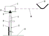
FIG. 1 is a schematic structural view of the present invention in an operating state;
FIG. 2 is a schematic structural view of the present invention;
fig. 3 is a schematic structural view of the leveling device of the present invention.
Detailed Description
The invention provides a telescopic leveling device and a detection method thereof, wherein the telescopic leveling device comprises a connecting base and a leveling device, the connecting base comprises a platform and a steel pipe vertically arranged on the platform, the leveling device comprises a centering rod telescopically arranged in the steel pipe and a level gauge arranged at the top of the centering rod, and the height of the level gauge is adjusted by changing the position of the centering rod in the steel pipe so as to measure.
The invention can arrange the platform on the buckling towers at two banks, measure the sag of the cable through the level, is not limited by the terrain during measurement, has wide application range, and simultaneously has the advantages of high construction efficiency and high measurement precision. The invention is described in detail below with reference to the drawings and the detailed description.
As shown in fig. 1, 2 and 3, a telescopic leveling device 13 provided by the present invention comprises a connection base and a leveling device 13.
The connecting base comprises a platform 11 horizontally arranged on the buckling tower 12 and a steel pipe 6 vertically arranged on the platform 11, the platform 11 is directly erected on the buckling tower 12, and the leveling device 13 is arranged on the steel pipe 6 of the platform 11, so that the connecting base is not limited by the terrain, and the application range is enlarged. The welding has reinforcing bar 7 around steel pipe 6, increases steel pipe 6's stability.
The leveling device 13 comprises a centering rod 4 which is telescopically arranged in a steel pipe 6 and a level gauge 1 which is arranged at the top of the centering rod 4, wherein the level gauge 1 has a leveling function. The top of centering rod 4 is equipped with adapter 3, and level 1 sets up on adapter 3, makes level 1 can the free rotation, is equipped with disc 2 between level 1 and the adapter 3, plays the effect of supporting level 1, and preferably, disc 2 adopts the steel material.
The middle part of disc 2 is equipped with the trompil that can supply the top of adapter 3 to stretch out, and disc 2 sets up is stretched out at the top of adapter 3 to make 1 rotations of surveyor's level set up at the top of adapter 3, the position of the adjustment surveyor's level 1 of being convenient for, simultaneously, be equipped with the scale mark on centering rod 4, be convenient for read the position of the relative steel pipe 6 of surveyor's level 1. According to the invention, the height of the level 1 is adjusted by adjusting the position of the centering rod 4 in the steel pipe 6, and the centering rod 4 is fixed by the locking device, so that the level 1 is prevented from shaking in the measuring process.
Preferably, the locking device is a threaded hole arranged on the outer wall of the steel pipe 6 and a screw rod 5 matched with the threaded hole, the centering rod 4 is inserted into the steel pipe 6, the centering rod 4 is propped against the end part of the centering rod 4 to complete fixation, the structure is simple, the use is convenient, and the disc 2 can drive the level gauge 1 to freely stretch and retract.
Be connected through the prism connector between centering rod 4 and the adapter 3, the diameter of the bottom of adapter 3 is the same with the internal diameter of prism connector, plays fixed adapter 3's effect, makes to connect more firmly.
The invention is not limited by the ground terrain, is suitable for measuring the cable sag in various terrains, is convenient to distinguish the cable strand, improves the measuring speed of the cable sag, saves the construction time, simultaneously uses the level gauge 1 to observe the central elevation of the cable strand, can weaken the influence of atmospheric refraction and earth curvature on the measuring precision to a greater extent, and has higher measuring precision.
The detection method comprises the following steps:
s1, lofting the designed verticality elevation 14 of the cable 15 to the two-bank buckling tower 12, wherein the designed elevation 14 is the position of the lowest point of the cable 15;
s2, arranging the platform 11 below the designed elevation 14 of the sag of the cable 15 on the two-bank buckling tower 12, and considering the factor that the sag of the temperature rise is reduced, the platform 11 is preferably arranged 1.5m below the designed elevation 14 of the sag of the cable 15;
s3, leading elevation points of the two banks to the platforms 11 of the two banks to obtain elevations H1 and H2, namely making elevation reference points on the platforms 11, measuring the elevations H1 and H2 of the reference points by using the total station instrument triangle elevation, welding steel pipes 6 on the platforms 11 of the two banks, welding reinforcing steel bars 7 around the steel pipes 6, and increasing the stability of the steel pipes 6;
s4, inserting the centering rod 4 of the leveling device 13 into the steel pipe 6, and locking the centering rod by the screwing screw 5 to complete erection of the leveling device 13;
s5, leveling the level 1, stretching the centering rod 4 to the minimum scale, erecting a leveling rod at the elevation point, reading readings A1 and A2 through the level 1, and obtaining the sight heights H1+ A1 and H2+ A2 of the level 1;
s6, observing the cable 15 using the leveling instrument 1, adjusting the position of the leveling instrument 1 by adjusting the centering rod 4 to make the horizontal line flush with the lowest point of the cable 15, reading the scales B1 and B2 on the centering rod 4, and obtaining the elevation H of the cable 15 as (H1+ a1+ B1+ H2+ a2+ B2)/2;
s7, adjusting the sag of the cable 15 according to the measured height of the cable 15.
The method for measuring the sag of the cable can ensure the quick operation of the sag measurement of the cable, save the time required by the conventional erection of the total station and the time for the conventional triangulation height measurement and cable separation, and is particularly suitable for the terrain in which the total station cannot be erected in mountainous areas. Meanwhile, the problems that the cable of the cable crane is high in height and large in span, and a mountainous terrain which is measured by adopting the suspension height is not available are solved, the spacing between adjacent cables is too small, the serial number of a main cable is difficult to distinguish, and the sag can not be accurately measured by a suspension height measuring method.
The present invention is not limited to the above-mentioned preferred embodiments, and any structural changes made under the teaching of the present invention shall fall within the scope of the present invention, which is similar or similar to the technical solutions of the present invention.
Claims (1)
1. A method for detecting cable sag, comprising the steps of:
s1, lofting the designed elevation of the cable sag to a buckling tower on two banks;
s2, arranging a platform 1.5m below the design standard height of the cable sag on the buckling towers at the two banks;
s3, leading elevation points of the two banks to the platforms of the two banks to obtain elevations H1 and H2, welding steel pipes on the platforms of the two banks, and welding reinforcing steel bars around the steel pipes;
s4, inserting the centering rod of the leveling device into the steel pipe, and locking the centering rod by screwing a screw;
s5, leveling the level, stretching the centering rod to the minimum scale, erecting a leveling rod at the elevation point, reading A1 and A2 to obtain the sight heights H1+ A1 and H2+ A2 of the level;
s6, observing the cable by using a leveling instrument, adjusting the position of the leveling instrument by adjusting the centering rod to enable the transverse wire of the leveling instrument to be flush with the lowest point of the cable, reading scales B1 and B2 on the centering rod, and obtaining the elevation H of the cable as (H1+ A1+ B1+ H2+ A2+ B2)/2;
and S7, adjusting the sag of the cable according to the measured elevation of the cable.
Priority Applications (1)
| Application Number | Priority Date | Filing Date | Title |
|---|---|---|---|
| CN201810580815.XA CN108645376B (en) | 2018-06-05 | 2018-06-05 | Telescopic leveling device and detection method thereof |
Applications Claiming Priority (1)
| Application Number | Priority Date | Filing Date | Title |
|---|---|---|---|
| CN201810580815.XA CN108645376B (en) | 2018-06-05 | 2018-06-05 | Telescopic leveling device and detection method thereof |
Publications (2)
| Publication Number | Publication Date |
|---|---|
| CN108645376A CN108645376A (en) | 2018-10-12 |
| CN108645376B true CN108645376B (en) | 2022-01-11 |
Family
ID=63752083
Family Applications (1)
| Application Number | Title | Priority Date | Filing Date |
|---|---|---|---|
| CN201810580815.XA Active CN108645376B (en) | 2018-06-05 | 2018-06-05 | Telescopic leveling device and detection method thereof |
Country Status (1)
| Country | Link |
|---|---|
| CN (1) | CN108645376B (en) |
Families Citing this family (1)
| Publication number | Priority date | Publication date | Assignee | Title |
|---|---|---|---|---|
| CN112033360B (en) * | 2020-09-17 | 2022-05-03 | 中交二航局第二工程有限公司 | Prism centering rod and prism centering rod height measuring method |
Citations (2)
| Publication number | Priority date | Publication date | Assignee | Title |
|---|---|---|---|---|
| JPS53148129A (en) * | 1977-05-30 | 1978-12-23 | Nippon Kokan Kk | Method of measuring sag in main cable for especially long suspension bridge |
| CN204359304U (en) * | 2015-01-31 | 2015-05-27 | 张昊然 | Portable stand fixed by spirit-leveling instrument |
Family Cites Families (4)
| Publication number | Priority date | Publication date | Assignee | Title |
|---|---|---|---|---|
| CN202092635U (en) * | 2011-05-18 | 2011-12-28 | 江西省水利规划设计院 | River-crossing leveling angle sighting target |
| CN108072357B (en) * | 2017-03-13 | 2020-04-21 | 湖南科技大学 | Level gauge with high-precision measuring function of instrument and using method thereof |
| CN107525496B (en) * | 2017-07-27 | 2019-12-31 | 中铁大桥局集团有限公司 | Device and method for measuring sag of cable of ultra-large span suspension bridge |
| CN108195362A (en) * | 2018-02-08 | 2018-06-22 | 中铁大桥局集团第五工程有限公司 | A kind of receiving platform and height transfer method transmitted for the vertical elevation of total powerstation |
-
2018
- 2018-06-05 CN CN201810580815.XA patent/CN108645376B/en active Active
Patent Citations (2)
| Publication number | Priority date | Publication date | Assignee | Title |
|---|---|---|---|---|
| JPS53148129A (en) * | 1977-05-30 | 1978-12-23 | Nippon Kokan Kk | Method of measuring sag in main cable for especially long suspension bridge |
| CN204359304U (en) * | 2015-01-31 | 2015-05-27 | 张昊然 | Portable stand fixed by spirit-leveling instrument |
Also Published As
| Publication number | Publication date |
|---|---|
| CN108645376A (en) | 2018-10-12 |
Similar Documents
| Publication | Publication Date | Title |
|---|---|---|
| CN105320596B (en) | A kind of bridge deflection test method and its system based on inclinator | |
| CN106679559B (en) | Device and method for actually measuring three-dimensional deformation of interior of ultrahigh earth-rock dam | |
| CN104567641B (en) | A kind of Short/Medium Span Bridge deflection measuring apparatus | |
| CN107234138A (en) | Mill housing aligning method | |
| CN110160488B (en) | Method and device for measuring elevation of special-shaped steel cable tower | |
| CN109537650B (en) | Slope wide-range finder and slope deformation real-time monitoring method | |
| CN108645376B (en) | Telescopic leveling device and detection method thereof | |
| CN206540548U (en) | The total powerstation of function is measured with instrument high precision | |
| CN113310466A (en) | Anti-slide pile deviation monitoring device and monitoring method | |
| CN111608213A (en) | Method and device for measuring horizontal displacement of foundation pit supporting pile | |
| CN212772499U (en) | Foundation ditch fender pile horizontal displacement's measuring device | |
| CN210533641U (en) | Bridge deflection measuring device | |
| CN209745999U (en) | Multi-dimensional positioning device for determining roadway wind speed | |
| CN217953468U (en) | Special device for monitoring settlement of pier in high-speed railway bridge water | |
| CN112346072B (en) | Method for measuring height of overhead pipeline in complex environment | |
| CN113280787B (en) | Bridge linear detection method based on opposite side height difference measurement | |
| CN210768731U (en) | High-precision measuring device for mine underground shaft and roadway | |
| CN214893219U (en) | Automatic monitoring device for vertical displacement of high formwork | |
| CN210426559U (en) | Coaxial support for simultaneously placing prism and GNSS antenna | |
| CN209197716U (en) | A kind of anchor pole checks and accepts displacement measuring device in experiment | |
| CN204282417U (en) | Dynamic measurement device | |
| CN217108907U (en) | Engineering detects with subsiding detection device | |
| CN219103989U (en) | Slope monitoring device | |
| CN220649478U (en) | Auxiliary device for measuring levelness of deck plates of ocean platform | |
| CN217155315U (en) | Pier stud verticality measuring device |
Legal Events
| Date | Code | Title | Description |
|---|---|---|---|
| PB01 | Publication | ||
| PB01 | Publication | ||
| SE01 | Entry into force of request for substantive examination | ||
| SE01 | Entry into force of request for substantive examination | ||
| GR01 | Patent grant | ||
| GR01 | Patent grant |