CN108603515B - Method for removing rotor blade, removing device for performing the method, and rotor set provided with the removing device - Google Patents
Method for removing rotor blade, removing device for performing the method, and rotor set provided with the removing device Download PDFInfo
- Publication number
- CN108603515B CN108603515B CN201680078006.8A CN201680078006A CN108603515B CN 108603515 B CN108603515 B CN 108603515B CN 201680078006 A CN201680078006 A CN 201680078006A CN 108603515 B CN108603515 B CN 108603515B
- Authority
- CN
- China
- Prior art keywords
- rod
- blade
- base
- front side
- respect
- Prior art date
- Legal status (The legal status is an assumption and is not a legal conclusion. Google has not performed a legal analysis and makes no representation as to the accuracy of the status listed.)
- Active
Links
Images


Classifications
-
- F—MECHANICAL ENGINEERING; LIGHTING; HEATING; WEAPONS; BLASTING
- F04—POSITIVE - DISPLACEMENT MACHINES FOR LIQUIDS; PUMPS FOR LIQUIDS OR ELASTIC FLUIDS
- F04D—NON-POSITIVE-DISPLACEMENT PUMPS
- F04D29/00—Details, component parts, or accessories
- F04D29/60—Mounting; Assembling; Disassembling
- F04D29/64—Mounting; Assembling; Disassembling of axial pumps
-
- F—MECHANICAL ENGINEERING; LIGHTING; HEATING; WEAPONS; BLASTING
- F01—MACHINES OR ENGINES IN GENERAL; ENGINE PLANTS IN GENERAL; STEAM ENGINES
- F01D—NON-POSITIVE DISPLACEMENT MACHINES OR ENGINES, e.g. STEAM TURBINES
- F01D5/00—Blades; Blade-carrying members; Heating, heat-insulating, cooling or antivibration means on the blades or the members
- F01D5/005—Repairing methods or devices
-
- B—PERFORMING OPERATIONS; TRANSPORTING
- B23—MACHINE TOOLS; METAL-WORKING NOT OTHERWISE PROVIDED FOR
- B23P—METAL-WORKING NOT OTHERWISE PROVIDED FOR; COMBINED OPERATIONS; UNIVERSAL MACHINE TOOLS
- B23P19/00—Machines for simply fitting together or separating metal parts or objects, or metal and non-metal parts, whether or not involving some deformation; Tools or devices therefor so far as not provided for in other classes
- B23P19/02—Machines for simply fitting together or separating metal parts or objects, or metal and non-metal parts, whether or not involving some deformation; Tools or devices therefor so far as not provided for in other classes for connecting objects by press fit or for detaching same
-
- B—PERFORMING OPERATIONS; TRANSPORTING
- B23—MACHINE TOOLS; METAL-WORKING NOT OTHERWISE PROVIDED FOR
- B23P—METAL-WORKING NOT OTHERWISE PROVIDED FOR; COMBINED OPERATIONS; UNIVERSAL MACHINE TOOLS
- B23P6/00—Restoring or reconditioning objects
- B23P6/002—Repairing turbine components, e.g. moving or stationary blades, rotors
-
- F—MECHANICAL ENGINEERING; LIGHTING; HEATING; WEAPONS; BLASTING
- F01—MACHINES OR ENGINES IN GENERAL; ENGINE PLANTS IN GENERAL; STEAM ENGINES
- F01D—NON-POSITIVE DISPLACEMENT MACHINES OR ENGINES, e.g. STEAM TURBINES
- F01D25/00—Component parts, details, or accessories, not provided for in, or of interest apart from, other groups
- F01D25/28—Supporting or mounting arrangements, e.g. for turbine casing
- F01D25/285—Temporary support structures, e.g. for testing, assembling, installing, repairing; Assembly methods using such structures
-
- F—MECHANICAL ENGINEERING; LIGHTING; HEATING; WEAPONS; BLASTING
- F01—MACHINES OR ENGINES IN GENERAL; ENGINE PLANTS IN GENERAL; STEAM ENGINES
- F01D—NON-POSITIVE DISPLACEMENT MACHINES OR ENGINES, e.g. STEAM TURBINES
- F01D5/00—Blades; Blade-carrying members; Heating, heat-insulating, cooling or antivibration means on the blades or the members
- F01D5/30—Fixing blades to rotors; Blade roots ; Blade spacers
- F01D5/3007—Fixing blades to rotors; Blade roots ; Blade spacers of axial insertion type
-
- F—MECHANICAL ENGINEERING; LIGHTING; HEATING; WEAPONS; BLASTING
- F02—COMBUSTION ENGINES; HOT-GAS OR COMBUSTION-PRODUCT ENGINE PLANTS
- F02C—GAS-TURBINE PLANTS; AIR INTAKES FOR JET-PROPULSION PLANTS; CONTROLLING FUEL SUPPLY IN AIR-BREATHING JET-PROPULSION PLANTS
- F02C7/00—Features, components parts, details or accessories, not provided for in, or of interest apart form groups F02C1/00 - F02C6/00; Air intakes for jet-propulsion plants
-
- F—MECHANICAL ENGINEERING; LIGHTING; HEATING; WEAPONS; BLASTING
- F04—POSITIVE - DISPLACEMENT MACHINES FOR LIQUIDS; PUMPS FOR LIQUIDS OR ELASTIC FLUIDS
- F04D—NON-POSITIVE-DISPLACEMENT PUMPS
- F04D29/00—Details, component parts, or accessories
- F04D29/26—Rotors specially for elastic fluids
- F04D29/32—Rotors specially for elastic fluids for axial flow pumps
- F04D29/321—Rotors specially for elastic fluids for axial flow pumps for axial flow compressors
- F04D29/322—Blade mountings
-
- F—MECHANICAL ENGINEERING; LIGHTING; HEATING; WEAPONS; BLASTING
- F04—POSITIVE - DISPLACEMENT MACHINES FOR LIQUIDS; PUMPS FOR LIQUIDS OR ELASTIC FLUIDS
- F04D—NON-POSITIVE-DISPLACEMENT PUMPS
- F04D29/00—Details, component parts, or accessories
- F04D29/26—Rotors specially for elastic fluids
- F04D29/32—Rotors specially for elastic fluids for axial flow pumps
- F04D29/34—Blade mountings
-
- F—MECHANICAL ENGINEERING; LIGHTING; HEATING; WEAPONS; BLASTING
- F05—INDEXING SCHEMES RELATING TO ENGINES OR PUMPS IN VARIOUS SUBCLASSES OF CLASSES F01-F04
- F05D—INDEXING SCHEME FOR ASPECTS RELATING TO NON-POSITIVE-DISPLACEMENT MACHINES OR ENGINES, GAS-TURBINES OR JET-PROPULSION PLANTS
- F05D2230/00—Manufacture
- F05D2230/70—Disassembly methods
-
- F—MECHANICAL ENGINEERING; LIGHTING; HEATING; WEAPONS; BLASTING
- F05—INDEXING SCHEMES RELATING TO ENGINES OR PUMPS IN VARIOUS SUBCLASSES OF CLASSES F01-F04
- F05D—INDEXING SCHEME FOR ASPECTS RELATING TO NON-POSITIVE-DISPLACEMENT MACHINES OR ENGINES, GAS-TURBINES OR JET-PROPULSION PLANTS
- F05D2260/00—Function
- F05D2260/30—Retaining components in desired mutual position
- F05D2260/38—Retaining components in desired mutual position by a spring, i.e. spring loaded or biased towards a certain position
Landscapes
- Engineering & Computer Science (AREA)
- Mechanical Engineering (AREA)
- General Engineering & Computer Science (AREA)
- Chemical & Material Sciences (AREA)
- Combustion & Propulsion (AREA)
- Turbine Rotor Nozzle Sealing (AREA)
- Structures Of Non-Positive Displacement Pumps (AREA)
Abstract
The detaching device is provided with a base (101), a pressing rod (130), a rod moving mechanism (150), and a rod guide (140). The base (101) is constrained so as not to be movable in the first direction (Z). The pressing rod (130) can protrude from the front surface (123) of the base (101) to the front side (Zf). The rod moving mechanism (150) is provided on the base (101). The rod moving mechanism (150) moves the pressing rod (130) to the front side (Zf). The rod guide (140) is attached to the base (101). The rod guide (140) guides the movement of the pressing rod (130) by the rod moving mechanism (150) in a second direction (U) that forms an acute angle with respect to the first direction (Z).
Description
Technical Field
The present invention relates to a method of removing a rotor blade in a rotary machine, a removing device for performing the method, and a rotor set including the removing device.
The present application claims priority based on Japanese application No. 2016-.
Background
An axial compressor, which is one type of rotary machine, includes a rotor that rotates about an axis, and a casing that covers the rotor. The rotor includes a rotor shaft and a plurality of rotor blade cascades attached to the rotor shaft. Each of the blade cascades is arranged on an upstream side of any one of the plurality of stationary blade cascades. The rotor blade cascade is composed of a plurality of rotor blades arranged in a circumferential direction with respect to the axis.
The following patent document 1 discloses the axial flow compressor. The rotor shaft of the axial flow compressor has a plurality of disks arranged in accordance with the respective moving blade rows. The plurality of disks are each formed in a circular plate shape centering on the axis. The rotor shaft is formed by stacking a plurality of disks in the axial direction. The bucket has: a blade body extending in a radial direction with respect to an axis to form a blade shape; and a blade root portion provided radially inside the blade main body. A blade root groove that is recessed from a radially outer side toward a radially inner side and extends in a direction having an axial component and into which a blade root is inserted is formed in the disk.
Prior art documents
Patent document
Patent document 1: japanese patent laid-open publication No. 2011-
Disclosure of Invention
Problems to be solved by the invention
In the rotary machine described in patent document 1, the blade root of the rotor blade may be fixed to the blade root groove during long-term operation. Therefore, in the inspection or repair of the rotary machine, it is sometimes difficult to remove the rotor blade from the blade root groove without damaging the rotor blade.
Therefore, an object of the present invention is to provide a technique for easily removing a rotor blade from a blade root groove without damaging the rotor blade.
Means for solving the problems
The present invention for achieving the above object is a device for removing a rotor blade, comprising: a base constrained from moving in a first direction; a pressing bar that can protrude from a front surface of the base, the front surface being one side facing the first direction, toward the front side; a rod moving mechanism provided on the base and configured to move the pressing rod to the front side; and a rod guide attached to the base and guiding movement of the pressing rod by the rod moving mechanism in a second direction that forms an acute angle with respect to the first direction.
The disk on which the rotor blade is mounted is formed in a disk shape with the axis as the center. The disk is formed with a blade root groove that is recessed from a radially outer side to a radially inner side with respect to the axis and extends in an oblique direction that is oblique to the axis. The blade root of the rotor blade enters the blade root slot. The rotor shaft is formed by stacking a plurality of disks in the axial direction. When the movable blade is removed by the removing device, the front surface of the base is brought into contact with an axial end surface of the disk facing the axial direction, and the end surface of the pressing rod on the front side is opposed to the blade root, so that the first direction of the removing device coincides with the axial direction in which the axis extends and the second direction of the removing device coincides with the oblique direction. By configuring the dismounting device in this way, the base cannot move in the first direction relative to the disc or the rotor shaft. Subsequently, the pressing rod is moved to the front side by the rod moving mechanism. The pressing bar is moved in a second direction at an acute angle with respect to the first direction by means of a bar guide. The second direction is a direction of inclination in which the blade root slot extends. Therefore, in the detaching device, the movable blade can be moved by pressing the movable blade in the direction in which the blade root groove extends by the pressing rod. Therefore, in this detaching device, the rotor blade can be easily detached from the blade root groove without damaging the rotor blade.
As a representative example of the base constrained so as not to be movable in the first direction, a structure is adopted in which the base has a front surface that is a vertical surface in the first direction.
Here, in the bucket detaching device, the base may include: a frame for the rod moving mechanism to be disposed and for the rod guide to be mounted; and a movement restricting mechanism that restricts movement of the frame in the first direction.
In this detaching device, since the movement restricting mechanism is provided, the movement of the base including the frame in the first direction can be restricted regardless of the size or shape of the frame.
In the device for detaching the movable blade having the movement restricting mechanism, the movement restricting mechanism may have a pressing member at least a part of which is disposed on the front side or the rear side opposite to the front side with respect to the frame.
In this detaching device, by disposing at least a part of the pressing member on the front side or the rear side of the frame, the movement of the base including the frame in the first direction can be restricted.
In the above-described bucket dismounting device having the movement restricting mechanism, the base may have a second movement restricting mechanism that restricts movement of the frame in a third direction perpendicular to the first direction and the second direction, in addition to the first movement restricting mechanism as the movement restricting mechanism, and the second movement restricting mechanism may have a surface facing one side of the third direction, that is, an arc surface that is arc-shaped around a virtual axis extending in the first direction and located on the one side of the third direction with respect to the base.
When the movable blade is removed by the removing device, the arc surface of the base is brought into contact with the outer peripheral surface of the disk or the rotor shaft, and the radial direction with respect to the disk or the rotor shaft is made to coincide with the third direction. By configuring the detaching device in this way, the base cannot move in one side of the third direction with respect to the disk or the rotor shaft.
In the bucket detaching device having the pressing member, the movement restricting mechanism may have a member separating mechanism that separates the pressing member from the frame in the first direction.
In this detaching device, the pressing member is moved in the first direction with respect to the frame by the member separating mechanism, and therefore, the movement of the base including the frame in the first direction can be easily restricted.
In any one of the above blade detaching devices, the rod guide may have a guide hole that penetrates in the second direction and is capable of sliding in contact with the pressing rod. The rod guide may be detachable from the base. In this case, a fixing member may be provided to fix the rod guide to the base.
In this detaching device, the movement of the pressing rod in each direction perpendicular to the second direction can be restricted.
The direction of inclination with respect to the axis sometimes varies depending on the disk. Therefore, if the rod guide is detachable from the base, the rod guide can be changed according to the disk, and therefore, the versatility of the detaching device can be improved.
In any one of the above-described moving blade detaching apparatuses, the rod moving mechanism may include a tapered forming body formed with a tapered surface facing the tip side, and the tapered surface of the tapered forming body may move the pressing rod to the tip side by moving the pressing rod in a state of being in contact with an end surface of the pressing rod on the back side opposite to the tip side.
In the above-described device for removing a rotor blade, the rod moving mechanism may include a tapered forming body having a tapered surface inclined with respect to a virtual surface perpendicular to the first direction and facing the front side, and the tapered forming body may be provided on the base so as to be relatively movable in a direction in which the tapered surface widens with respect to a rear-side end surface opposite to the front side of the pressing rod in a state in which the tapered surface is in contact with the rear-side end surface.
In the detaching device having the tapered forming body, the pressing rod can be moved to the front side by moving the tapered forming body. Therefore, in this detaching device, the bucket can be moved without applying an impact load to the bucket.
In the apparatus for detaching the rotor blade having the tapered forming body, the rod moving mechanism may have a rotation center shaft to which the tapered forming body is attached so as to be rotatable about the rotation center shaft, and the tapered surface may extend in a circumferential direction with respect to the rotation center shaft.
In this detaching device, the tapered surface extends in the circumferential direction with respect to the rotation center axis, and therefore, the tapered formed body can be downsized as compared with the case where the tapered surface extends linearly.
In the device for detaching the rotor blade having the rotation center shaft, the tapered forming body may include: a rotating plate that rotates around the rotation center axis; and a handle extending from an outer periphery of the rotating plate in a radial direction with respect to the rotation center axis, wherein the tapered surface is formed on the rotating plate.
In this detaching device, the tapered forming body is rotated by operating the handle. Therefore, in this detaching device, the distance from the rotation center axis serving as a fulcrum to the handle serving as a force point is longer than the distance from the rotation center axis serving as a fulcrum to the tapered surface serving as an action point. Therefore, in this detaching device, the tapered forming body can be rotated with a small force. In other words, in the detaching device, the pressing rod can be moved to the front side with a small force.
In the above-described bucket detaching device, the rod moving mechanism may include: an external thread which is in contact with an end surface of a rear side of the pressing rod opposite to the front side; and a screw hole provided in the base, having an internal thread to which the external thread can be screwed, and extending in the first direction.
In this detaching device, the pressing rod can be moved to the front side by screwing the male screw into the screw hole. Therefore, in this detaching device, the bucket can be moved without applying an impact load to the bucket.
In any one of the above-described bucket removing devices, the rod moving mechanism may include an actuator that generates a force to move the pressing rod to the front side.
In this detaching device, the pressing rod can be moved by driving the actuator.
In addition, a rotor set according to an aspect of the present invention for achieving the above object includes: a device for detaching any one of the above rotor blades; a rotor shaft; and a plurality of movable blades attached to an outer circumferential side of the rotor shaft, the movable blades having: a blade main body extending in a radial direction with respect to the rotor shaft and forming a blade shape; and a blade root portion provided on a radially inner side of the blade body, wherein a blade root portion groove is formed in the rotor shaft, the blade root portion groove being recessed from a radially outer side toward a radially inner side and extending in an oblique direction forming an acute angle with respect to an axial direction in which the rotor shaft extends, for insertion of the blade root portion, and an angle formed by the second direction with respect to the first direction is identical to an angle formed by the oblique direction with respect to the axial direction.
A rotor set according to another aspect of the present invention for achieving the above object includes: the rod guide has a device for detaching the bucket of the guide hole; a rotor shaft; and a plurality of movable blades attached to an outer circumferential side of the rotor shaft, the movable blades having: a blade main body extending in a radial direction with respect to the rotor shaft and forming a blade shape; and a blade root provided on a radially inner side of the blade body, the rotor shaft having a blade root groove formed therein, the blade root groove being recessed from a radially outer side toward a radially inner side and extending in a diagonal direction at an acute angle with respect to an axial direction in which the rotor shaft extends, for insertion of the blade root, an angle of the second direction with respect to the first direction being coincident with an angle of the diagonal direction with respect to the axial direction, the dismounting device having, in addition to a first rod guide as the rod guide, a second rod guide having a second guide hole of a shape different from a shape of the guide hole of the first rod guide. The shape of the guide hole includes both a cross-sectional shape of the guide hole perpendicular to the penetrating direction and a second direction, which is the penetrating direction of the guide hole, different from the first direction.
The direction of inclination with respect to the axis sometimes varies depending on the disk. Further, the shape of the end surface of the blade root may vary depending on the disk. In this rotor set, the rod guide can be changed according to the disk, and therefore, the versatility of the dismounting device can be improved.
A method of removing a rotor blade according to an aspect of the present invention for achieving the above object is a method of removing a rotor blade attached to an outer circumferential side of a rotor shaft, the rotor blade including: a blade main body extending in a radial direction with respect to the rotor shaft and forming a blade shape; and a blade root provided radially inward of the blade body, the rotor shaft having a blade root groove formed therein, the blade root groove being recessed radially inward from a radially outer side and extending in an oblique direction at an acute angle with respect to an axial direction in which the rotor shaft extends, and into which the blade root is inserted, the method for removing the rotor blade performing a preparation step in which a removing device is prepared, a placement step, and a bar moving step, the removing device including: a base constrained from moving in a first direction; a pressing bar that can protrude from a front surface of the base, the front surface being one side facing the first direction, toward the front side; a rod moving mechanism provided on the base and configured to move the pressing rod to the front side; and a rod guide attached to the base and guiding movement of the pressing rod by the rod moving mechanism in a second direction that forms an acute angle with respect to the first direction, wherein in the arranging step, the base of the detaching device is arranged such that the front surface of the base is in contact with an axial end surface of the rotor shaft facing the axial direction, and the end surface of the pressing rod on the front side is opposed to the blade root, and the first direction is aligned with the axial direction and the second direction is aligned with the oblique direction, and in the rod moving step, the pressing rod is moved to the front side by the rod moving mechanism.
Here, in the method for removing the rotor blade, the preparation step may include: a rod guide preparation step of preparing a plurality of rod guides each having a guide hole penetrating in the second direction and having a different shape from each other, and a pressing rod corresponding to the plurality of rod guides; a selection step of selecting a bar guide having a guide hole corresponding to the shape of the blade root from the plurality of bar guides, and selecting a pressing bar corresponding to the selected bar guide; and a rod guide mounting step of mounting the rod guide selected in the selection step on the base and causing the pressing rod selected in the selection step to follow the rod guide.
In any one of the above-described methods for removing the rotor blade, the base in the removing device prepared in the preparation step may include: a frame for the rod moving mechanism to be disposed and for the rod guide to be mounted; and a pressing member at least a part of which is disposed on the front side or the rear side opposite to the front side of the frame, wherein in the disposing step, the pressing member is disposed on the front side or the rear side of the frame, and the pressing member is brought into contact with an axial end surface of the rotor shaft in the axial direction.
In any one of the above methods for removing the rotor blade, the base in the removing device prepared in the preparation step may include: a frame for the rod moving mechanism to be disposed and for the rod guide to be mounted; a pressing member at least a part of which is disposed on the front side of the frame or on the rear side opposite to the front side; and a member separating mechanism that separates the pressing member from the frame in the first direction, wherein in the disposing step, the pressing member is moved in the first direction by the member separating mechanism, and the front surface of the base is brought into contact with an axial end surface of the rotor shaft facing the axial direction.
In any of the above-described methods of removing the rotor blade, the rod moving mechanism in the removing device prepared in the preparation step may have a tapered forming body in which a tapered surface facing the tip side is formed, and the rod moving step may move the pressing rod to the tip side by moving the tapered surface of the tapered forming body in a state of being in contact with an end surface of the pressing rod on a rear side opposite to the tip side.
In this case, the rod moving mechanism in the detaching device prepared in the preparation step may have a rotation center shaft to which the tapered forming body is rotatably attached around the rotation center shaft, the tapered surface may extend in a circumferential direction with respect to the rotation center shaft, and the rod moving step may rotate the tapered forming body around the rotation center shaft.
In any one of the above methods for removing the rotor blade, the rod moving mechanism in the removing device prepared in the preparation step may include: a threaded hole provided in the base and having an internal thread formed therein; and a male screw that can be screwed into the female screw of the screw hole, wherein in the rod moving step, the pressing rod is moved to the front side by rotating the male screw.
Effects of the invention
According to an aspect of the present invention, the rotor blade can be easily removed from the blade root groove without damaging the rotor blade.
Drawings
Fig. 1 is a schematic sectional view of a gas turbine in an embodiment of the present invention.
Fig. 2 is a main part sectional view of a compressor rotor in an embodiment of the present invention.
Fig. 3 is a plan view of a main portion of a compressor rotor according to an embodiment of the present invention, as viewed from the radially outer side.
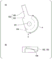
Fig. 4 is a main part perspective view of a compressor rotor in an embodiment of the present invention.
Fig. 5 is a plan view of a first dismounting device in an embodiment of the present invention.
Fig. 6 is a sectional view taken along line VI-VI in fig. 5.
Fig. 7 is a view in direction VII of fig. 5.
Fig. 8 is a view showing a tapered formation body in an embodiment of the present invention. Fig. (a) is a front view of the tapered formed body, and fig. (B) is a view from B in fig. (a).
Fig. 9 is a perspective view of the disk, the movable blade, and the pressing bar according to the embodiment of the present invention.
Fig. 10 is a plan view of a main part of the disk, the rotor blade, and the detaching device after the disposing step in the embodiment of the present invention.
Fig. 11 is a plan view of a main part of the disk, the rotor blade, and the detaching device after the rod moving step in the embodiment of the present invention.
Fig. 12 is a flowchart showing steps of a method for detaching a bucket according to an embodiment of the present invention.
Fig. 13 is a front view of a main part of a detaching device in a first modification of the embodiment of the present invention with a notch.
Fig. 14 is a plan view of a main part of the disk, the rotor blade, and the detaching device after the disposing step in the first modification of the embodiment of the present invention.
Fig. 15 is a plan view of a main part of the disk, the rotor blade, and the detaching device after the disposing step in the second modification of the embodiment of the present invention.
Fig. 16 is a plan view of a main part of the disk, the rotor blade, and the detaching device after the disposing step in the third modification of the embodiment of the present invention.
Detailed Description
Hereinafter, an embodiment of the present invention and its modified examples will be described in detail with reference to the drawings.
"embodiment of rotating machine"
An embodiment of a rotary machine will be described with reference to fig. 1 to 4.
The rotary machine of the present embodiment is a compressor of a gas turbine. As shown in fig. 1, the gas turbine 1 includes: a compressor 30 for compressing the air a; a combustor 20 that combusts fuel F in air a compressed by a compressor 30 to generate combustion gas G; and a turbine 10 driven by the combustion gas G.
The compressor 30 includes a compressor rotor 31 that rotates about an axis Ar, a compressor casing 35 that covers the compressor rotor 31, and a plurality of stationary blade cascades 37. The turbine 10 includes a turbine rotor 11 that rotates about an axis Ar, a turbine casing 15 that covers the turbine rotor 11, and a plurality of stationary blade cascades 17.
The compressor rotor 31 and the turbine rotor 11 are located on the same axis Ar and are connected to each other to form the gas turbine rotor 2. A rotor of the generator GEN is connected to the gas turbine rotor 2, for example. Further, the compressor casing 35 and the turbine casing 15 are connected to each other to form the gas turbine casing 5. In the following, the direction in which the axis Ar extends is referred to as the axial direction Da, the circumferential direction around the axis Ar is referred to as only the circumferential direction Dc, and the direction perpendicular to the axis Ar is referred to as the radial direction Dr. The compressor 30 side with respect to the turbine 10 in the axial direction Da is referred to as an upstream side Dau, and the opposite side is referred to as a downstream side Dad. Further, a side close to the axis Ar in the radial direction Dr is a radial inner side Dri, and an opposite side is a radial outer side Dro.
The turbine rotor 11 includes a rotor shaft 12 extending in the axial direction Da about the axis Ar, and a plurality of rotor blade cascades 13 attached to the rotor shaft 12. The plurality of moving blade cascades 13 are aligned in the axial direction Da. Each of the rotor blade cascade 13 is composed of a plurality of rotor blades arranged in the circumferential direction Dc. A stationary blade cascade 17 is disposed on each upstream side Dau of the plurality of rotor blade cascades 13. Each stationary blade cascade 17 is disposed inside the turbine casing 15. Each of the vane cascades 17 is constituted by a plurality of vanes arranged in the circumferential direction Dc.
The compressor rotor 31 includes a rotor shaft 32 extending in the axial direction Da about the axis Ar, and a plurality of rotor blade cascades 33 attached to the rotor shaft 32. The plurality of moving blade cascades 33 are aligned in the axial direction Da. Each of the rotor blade cascade 33 is composed of a plurality of rotor blades 60 arranged in the circumferential direction Dc. A stationary blade cascade 37 is disposed on each downstream Dad of the plurality of blade cascades 33. Each stationary blade cascade 37 is disposed inside the compressor casing 35. Each of the stationary blade cascades 37 is constituted by a plurality of stationary blades arranged in the circumferential direction Dc. An annular space between the outer peripheral side of the rotor shaft 32 and the inner peripheral side of the compressor chamber 35 forms an air compression flow passage 39 through which air flows and compresses the air.
As shown in fig. 2, the rotor shaft 32 of the compressor 30 has a plurality of disks 40 arranged in accordance with the respective moving blade cascade 33. Each of the plurality of disks 40 is formed in a circular plate shape with the axis Ar as the center. The rotor shaft 32 is configured by stacking a plurality of disks 40 in the axial direction Da. The bucket 60 includes: a blade main body 61 extending in a radial direction with respect to the axis Ar to form a blade shape; and a blade root 62 provided at a radially inner side Dri of the blade main body 61.
The disk-shaped disk 40 is formed with a rotor blade mounting portion 41, an arm 53, and a recess 55. The bucket mounting portion 41 forms a portion of the radially outer side Dro of the disk 40. The arm 53 has: an upstream arm 53u located radially inward Dri of the rotor blade mounting portion 41 and protruding from the upstream Dau of the rotor blade mounting portion 41 to the upstream Dau; and a downstream arm 53d located radially inward Dri of the rotor blade mounting portion 41 and protruding from a downstream side Dad of the rotor blade mounting portion 41 toward the downstream side Dad. The upstream-side arm 53u and the downstream-side arm 53d each extend in the circumferential direction Dc and are formed annularly around the axis Ar. The recess 55 has: an upstream-side concave portion 55u located radially inward Dri of the upstream-side arm 53u and recessed toward the downstream side Dad relative to the upstream-side arm 53 u; and a downstream side recess 55d located radially inward Dri of the downstream side arm 53d and recessed toward the upstream side Dau relative to the downstream side arm 53 d. The upstream-side recess 55u and the downstream-side recess 55d each extend in the circumferential direction Dc and are annular about the axis Ar.
The rotor blade mounting portion 41 is formed with a plurality of blade root grooves 45 recessed from the radial outer side Dro toward the radial inner side Dri and extending in a direction including the axial Da component. The blade root 62 of the bucket 60 enters each blade root slot 45. The rotor blade mounting portion 41 is further formed with a cylindrical pin hole 49 recessed radially inward Dri from the groove bottom surface 48 of the blade root groove 45. A columnar pin 58 and a spring 59 for biasing the pin 58 in a direction protruding from the pin hole 49 are disposed in the pin hole 49. The blade root 62 of the rotor blade 60 is formed with a pin hole 69 recessed from the radially inner side Dri to the radially outer side Dro. The pin 58 protruding from the pin hole 49 of the disk 40 enters the pin hole 69.
As shown in fig. 3 and 4, the gas passage surface 42 facing the radially outer side Dro, the tip end surface 43 facing the upstream side Dau, and the rear end surface 44 facing the downstream side Dad are formed on the rotor blade mounting portion 41 of the disk 40. The gas passage surface 42 defines a part of the edge of the radially inner side Dri of the annular air compression flow passage 39. The front end surface 43 and the rear end surface 44 are surfaces substantially perpendicular to the axis Ar. The plurality of blade root grooves 45 are recessed radially inward Dri from the gas passage surface 42 at intervals in the circumferential direction Dc. The blade root groove 45 extends in the oblique direction Di with respect to the axis Ar from the rear end surface 44 to the front end surface 43 of the disk 40. The inclination direction Di is a direction at an acute angle with respect to the axial direction Da. The blade root groove 45 includes: a first groove portion 46 having a groove width in the circumferential direction Dc of a first groove width; and a second groove portion 47 having a second groove width wider than the first groove width in the circumferential direction Dc. The second groove portion 47 is located radially inward Dri of the first groove portion 46, and is continuous with the first groove portion 46.
The blade root 62 of the rotor blade 60 has a gas passage surface 63 facing the radially outer side Dro, a bottom surface 68 facing the radially inner side Dri, a tip end surface 64 facing the upstream side Dau, and a rear end surface 65 facing the downstream side Dad. The gas passage surface 63 defines a part of the edge of the radially inner side Dri of the annular air compression flow passage 39. The blade body 61 of the rotor blade 60 extends radially outward Dro from the gas passage surface 63. The blade root 62 has: a first blade root portion 66 having a width in the circumferential direction Dc of a first blade root width; and a second blade root portion 67 having a width in the circumferential direction Dc that is a second blade root width that is wider than the first blade root width. The second blade root portion 67 is located radially inward Dri of the first blade root portion 66 and is connected to the first blade root portion 66. The gas passage face 63 of the blade root 62 is formed at the first blade root portion 66. The first blade root width dimension is slightly smaller than, but substantially the same as, the first slot width dimension previously described. The second blade root width dimension is slightly smaller than the second slot width dimension previously described, but is substantially the same as the second slot width dimension. Therefore, in a state where the blade root 62 enters the blade root groove 45, even if centrifugal force acts on the rotor blade 60, the blade root 62 does not fall off from the blade root groove 45. In this state, when the compressor 30 is operated for a long time, the blade root 62 may be fixed to the blade root groove 45. A bottom surface 68 of blade root 62 is formed at second blade root portion 67. A forward end surface 64 and an aft end surface 65 of blade root 62 are formed in a first blade root portion 66 and a second blade root portion 67. The pin hole 69 of the rotor blade 60 is recessed toward the radially outer side Dro from the bottom surface 68 of the rotor blade 60. The pin 58 inserted into the pin hole 69 functions to restrict the movement of the bucket 60 in the pitch direction Di in which the blade root groove 45 extends.
In a state where the blade root 62 of the bucket 60 enters the blade root groove 45 of the disk 40, the leading end surface 64 of the blade root 62 is substantially coplanar with the leading end surface 43 of the disk 40. Further, the aft end face 65 of the blade root 62 is substantially coplanar with the aft end face 44 of the disk 40. Therefore, in this state, the leading end surface 64 and the trailing end surface 65 of the blade root 62 are surfaces substantially perpendicular to the axis Ar.
"embodiment of the dismounting device"
An embodiment of the detaching device will be described with reference to fig. 5 to 12.
The detaching device of the present embodiment is a device that detaches the rotor blade 60 from the blade root groove 45 of the disk 40 described above. As shown in fig. 5 to 7, the detaching device 100 of the present embodiment includes: a base 101 constrained so as not to be movable in a first direction, i.e., a Z direction; a pressing rod 130 that can protrude from the base 101 to the front side Zf that is one side in the Z direction; a rod moving mechanism 150 that moves the pressing rod 130 to the front side Zf; and a rod guide 140 for guiding the moving direction of the pressing rod 130. In the following, the other side in the Z direction, i.e., the side opposite to the front side Zf, is referred to as the rear side Zr. The direction perpendicular to the Z direction and the X direction is referred to as a Y direction, and the direction perpendicular to the Z direction and the Y direction is referred to as an X direction.
The base 101 has: a frame 110 to which the rod moving mechanism 150 is provided and to which the rod guide 140 is mounted; and a movement restricting mechanism 120 that restricts movement of the frame 110 in the Z direction. The frame 110 has: a front wall plate 111 and a rear wall plate 115 which are widened in a direction perpendicular to the Z direction; and a connecting portion 119 connecting the front wall panel 111 and the rear wall panel 115. The rear wall plate 115 is disposed at a distance from the rear side Zr with respect to the front wall plate 111. The connecting portion 119 connects the (-) Y-side edge of the front panel 111 and the (-) Y-side edge of the rear panel 115. The surface of the coupling portion 119 facing the (-) Y side is an arc-shaped arc surface 119a centered on a virtual axis located closer to the (-) Y side than the coupling portion 119 and extending in the Z direction. The face of the front wall panel 111 facing the front side Zf forms a front surface 112 of the frame 110. In addition, the face of the rear wall panel 115 facing the rear side Zr forms the rear surface 116 of the frame 110 and forms the rear surface of the base 101. The front surface 112 and the rear surface 116 of the frame 110 are surfaces parallel to each other and perpendicular to the Z-direction.
The movement restricting mechanism 120 has: a pressing member 121 having a part thereof disposed on the front side Zf of the front surface 112 of the frame 110; and a member separating mechanism 127 that separates the pressing member 121 toward the front side Zf with respect to the frame 110.
As shown in fig. 5, the pressing member 121 includes: a main board disposed on the front side Zf of the front surface 112 of the frame 110; a side plate 124 extending from the (+/-) X-side end of the main plate 122 to the rear side Zr; and a retaining plate 125 extending in the X direction from the rear Zr end of each side plate 124. The main board 122 is disposed parallel to the front surface 112 of the frame 110. The width of the main board 122 in the X direction is substantially the same as the width of the frame 110 in the X direction. The (+) X-side retaining plate 125 extends from the rear Zr end of the (+) X-side plate 124 toward the (-) X side. The stopper plate 125 on the (-) X side extends from the rear Zr end of the side plate 124 on the (-) X side to the (+) X side. Each of the retaining plates 125 faces the surface of the front wall plate 111 facing the rear side Zr in the Z direction. The Z-direction spacing between the main plate 122 and each retaining plate 125 is larger than the Z-direction width of the front wall plate 111, in other words, larger than the thickness of the front wall plate 111. Therefore, although the pressing member 121 can move in the Z direction with respect to the front wall plate 111, the moving range thereof is limited.
The member detaching mechanism 127 includes a detaching bolt 128 and an operating rod 129 for rotating the detaching bolt 128. A screw hole 113 penetrating in the Z direction is formed in the front wall plate 111. The male screw portion of the separation bolt 128 is screwed into the screw hole 113. The operation rod 129 is attached to the head of the separation bolt 128. The tip of the separation bolt 128 is in contact with the main plate 122 of the pressing member 121. When the separation bolt 128 is screwed into the screw hole 113 of the front wall plate 111, the pressing member 121 is pressed toward the front side Zf by the separation bolt 128, and the main plate 122 of the pressing member 121 is separated toward the front side Zf with respect to the frame 110. The face of the main plate 122 facing the front side Zf forms the front face 123 of the base 101.
As shown in fig. 10, the rod guide 140 has a body portion 141, and a flange portion 145 extending from the outer periphery of the body portion 141 to the outer peripheral side. A guide fitting hole 114 into which the body portion 141 of the rod guide 140 enters is formed in the front wall plate 111 of the frame 110. The body portion 141 of the rod guide 140 enters the guide fitting hole 114. The flange portion 145 of the rod guide 140 is fixed to the front wall plate 111 of the frame 110 by a screw 146 as a fixing member. A guide hole 142 that penetrates in the U direction (second direction) that forms an acute angle with respect to the Z direction (first direction) is formed in the body portion 141 of the rod guide 140.
As shown in fig. 9 and 10, the pressing bar 130 includes a slot insertion portion 132, a body portion 136, and a tail portion 137. The pressing bar 130 has a bar shape. The first end side of the pressing rod 130 forms a groove insertion portion 132. A second end side of the pressing bar 130 opposite to the first end side forms a tail 137. The trunk portion 136 is formed between the slot insertion portion 132 and the tail portion 137. The body portion 136 is inserted into the guide hole 142 of the rod guide 140. The outer peripheral surface of the body 136 is in contact with the inner peripheral surface of the guide hole 142. The cross-sectional shape of the groove insertion portion 132 in the plane perpendicular to the Z direction corresponds to the cross-sectional shape of the blade root 62 perpendicular to the axial direction Da. Therefore, the slot inserting portion 132 has: a first groove insertion portion 133 having a first width in the X direction perpendicular to the Z direction; and a second slot insertion portion 134 having a width in the X direction of a second width wider than the first width. The second slot insertion portion 134 is located on the (-) Y side of the first slot insertion portion 133. The first width is slightly narrower than the aforementioned first blade root width. The second width is slightly narrower than the aforementioned second blade root width. The surface of the groove insertion portion 132 facing the first end side forms a pressing surface 135 that contacts the end surface of the blade root portion 62. The pressing surface 135 is a surface perpendicular to the Z direction and parallel to the front surface 123 of the base 101. The cross-sectional shape of the tail 137 perpendicular to the Y direction is formed into a semicircular shape protruding toward the rear side Zr. Therefore, the rear end surface 138 of the pressing rod 130 is formed in an arc shape.
As shown in fig. 5 to 8, the rod moving mechanism 150 includes: a rotation center shaft 151 extending in the Z direction; and a tapered formation body 152 that rotates about the rotation center axis 151. A first end of the rotation center shaft 151 is supported by the front wall plate 111 of the frame 110, and a second end of the rotation center shaft 151 is supported by the rear wall plate 115 of the frame 110. The tapered forming body 152 includes a rotating plate 153 and a handle 155 provided on the outer periphery of the rotating plate 153. The rotating plate 153 is formed in an arc shape in which a part of a circular plate centered on the rotation center axis 151 is cut off. The rotating plate 153 is provided to be rotatable about the rotation center axis 151 with respect to the rotation center axis 151. The rotating plate 153 has a tapered surface 154 inclined with respect to a surface perpendicular to the Z direction and facing the front side Zf. As shown in fig. 8 and 10, the tapered surface 154 extends in the circumferential direction with respect to the rotation center axis 151, and is formed in a region R of a predetermined angle with respect to the rotation center axis 151. The tapered surface 154 is contiguous with the rear end surface 138 of the press bar 130. Fig. 8 (a) is a front view of the tapered forming body 152, and fig. (B) is a view from B in fig. (a).
Next, a method of removing the bucket 60 will be described with reference to a flowchart shown in fig. 12.
First, the detaching apparatus 100 described above is prepared (S1: preparation step). In the plurality of disks 40 constituting the rotor shaft 32 of the compressor 30, the direction in which the blade root groove 45 extends may be slightly different between the disks 40, and the size of the blade root groove 45 may be slightly different. In such a case, it is preferable to prepare the rod guide 140 and the pressing rod 130 corresponding to the blade root groove 45 of each disk 40 in advance (S1 a: rod guide preparation step). In this case, the rod guide 140 corresponding to the blade root groove 45 of the disk 40 (hereinafter referred to as the target disk 40) to which the rotor blade 60 to be detached (hereinafter referred to as the target rotor blade 60) is attached is selected from the plurality of rod guides 140, and the pressing rod 130 corresponding to the selected rod guide 140 is selected from the plurality of pressing rods 130(S1 b: selection step). Here, as shown in fig. 10, the rod guide 140 corresponding to the blade root groove 45 of the disk 40 is the rod guide 140 in which the angle of the U direction in which the guide hole 142 extends with respect to the Z direction coincides with the angle of the inclination direction Di in which the blade root groove 45 extends with respect to the axis Ar. The pressing rod 130 corresponding to the selected rod guide 140 is the pressing rod 130 in which the body portion 136 of the pressing rod 130 can be inserted into the guide hole 142 of the rod guide 140 and the outer peripheral surface of the body portion 136 is in contact with the inner peripheral surface of the guide hole 142. Next, the pressing rod 130 selected in the selection step (S1b) is fitted into the guide hole 142 of the rod guide 140, and the rod guide 140 is fixed to the frame 110 by the screw 146 (S1 c: rod guide attachment step).
In the present embodiment, the rotor group is configured by including one or more disks 40, the target rotor blades 60, and the dismounting device 100.
Next, the base 101 of the dismounting device 100 is disposed so that the blade root 62 of the target rotor blade 60 faces the pressing surface 135 of the pressing bar 130 (S2: disposing step). In this arranging step (S2), first, the base 101 of the detaching device 100 is arranged between the target disk 40 and the disk 40 adjacent to the target disk 40 in the axial direction Da (S2 a: temporary arranging step). Specifically, for example, as shown in fig. 5, 7, and 10, the susceptor 101 is disposed between the target disk 40 and the disk 40 on the upstream side Dau adjacent to the target disk 40. At this time, the front surface 123 of the base 101 is disposed to face the front end surface 43 of the target disk 40, and the front end surface 64 of the blade root 62 of the target rotor blade 60 is disposed to face the pressing surface 135 of the pressing rod 130. The arc surface 119a of the base 101 is disposed so as to contact the outer peripheral surface of the disk 40. When the arc surface 119a of the base 101 comes into contact with the outer peripheral surface of the object disk 40, the base 101 of the detaching device 100 is restrained so as not to be movable in the (-) Y direction. The (-) Y direction is the radial direction inner Dri of the target disk 40 in this state.
Next, in this disposing step (S2), the operation rod 129 of the member separating mechanism 127 is operated, and the separating bolt 128 of the member separating mechanism 127 is screwed into the screw hole 113 of the front wall plate 111. When the separation bolt 128 is screwed into the screw hole 113, the pressing member 121 is pressed toward the front side Zf by the separation bolt 128, and the main plate 122 of the pressing member 121 moves toward the front side Zf with respect to the frame 110 and comes into contact with the front end surface 43 of the target disk 40. Here, the separation bolt 128 is further screwed into the screw hole 113, and the main plate 122 of the pressing member 121 is brought into close contact with the front end surface 43 of the target disk 40. That is, the front surface 123 of the base is brought into close contact with the front end surface 43 of the target disk 40. When the main plate 122 of the pressing member 121 is brought into close contact with the front end surface 43 of the target disk 40, the rear surface 116 of the base 101 is brought into close contact with the rear end surface 44 of the disk 40 on the upstream side Dau. As a result, the base 101 of the detaching apparatus 100 is restrained so as not to be movable in the Z direction with respect to the target disk 40 (S2 b: main disposing step). In the main disposing step (S2b), it is preferable that the position of the base 101 of the detaching device 100 be finely adjusted such that the tip surface 64 of the blade root 62 of the target rotor blade 60 faces the pressing surface 135 of the pressing rod 130 again at the stage where the tip surface 123 of the base 101, that is, the surface of the main plate 122 of the pressing member 121 facing the front side Zf, comes into contact with the tip surface 43 of the target disk 40. The disposing step (S2) is completed.
When the disposing step (S2) is completed, as shown in fig. 5 and 10, the blade root 62 of the target rotor blade 60 faces the pressing surface 135 of the pressing bar 130. Further, the Z direction in the dismounting device 100 coincides with the axial direction Da of the disk 40, and the U direction in the dismounting device 100 coincides with the tilt direction Di of the disk 40. Further, the Y direction in the dismounting device 100 coincides with the radial direction Dr of the disk 40, and the X direction in the dismounting device 100 substantially coincides with the circumferential direction Dc of the disk 40.
Subsequently, the pressing rod 130 is moved to the front side Zf by the rod moving mechanism 150 (S3: rod moving step). In this rod moving step (S3), as shown in fig. 6, the handle 155 of the tapered forming body 152 is operated to rotate the tapered forming body 152 about the rotation center axis 151. When the tapered forming body 152 rotates, the tapered surface 154 formed on the tapered forming body 152 also rotates about the rotation center axis 151. The rear end surface 138 of the press rod 130 contacts the tapered surface 154. Therefore, when the tapered surface 154 rotates, as shown in fig. 11, the contact position in the tapered surface 154 with the pressing rod 130 changes. As a result, the pressing rod 130 is pushed out by the tapered forming body 152 toward the front side Zf in the Z direction. Since the moving direction of the pressing rod 130 is restricted in the U direction by the rod guide 140, the pressing rod 130 moves to the front side in the U direction. When the pressing rod 130 moves forward in the U direction, the groove insertion portion 132 of the pressing rod 130 protrudes from the front surface 123 of the base 101, and the pressing surface 135 of the pressing rod 130 comes into contact with the tip surface 64 of the blade root 62 of the bucket 60 to be removed. When the handle 155 of the tapered formation body 152 is further operated to move the pressing rod 130 to the front side in the U direction, the groove insertion portion 132 of the pressing rod 130 enters the blade root groove 45 of the target disk 40. In this process, the target bucket 60 moves to the front side (downstream side) in the pitch direction Di. The moving amount of the blades 60 in the pitch direction Di is equal to or larger than the outer diameter of the pin 58 (see fig. 2). Therefore, the pin 58 is cut by the movement of the target bucket 60.
When the rotor blade 60 moves in the pitch direction Di, the fixed state of the blade root 62 to the blade root groove 45 is released, and the pin 58 that restricts the movement of the rotor blade 60 is cut. Therefore, the bucket 60 can easily move in the pitch direction Di in which the blade root groove 45 extends.
Subsequently, the movable blade 60 that can easily move in the pitch direction Di is moved further in the pitch direction Di to take out the blade root 62 of the movable blade 60 from the blade root groove 45 (S4: movable blade drawing step). In this way, the detachment of the target blade 60 is completed. Thereafter, if necessary, the other rotor blades 60 attached to the target disk 40 are also detached from the target disk 40 in the same manner as described above. However, when the other blade 60 is continuously removed, the preparation process (S1) does not need to be performed again.
The U direction (second direction) in the detaching device 100 after the disposing step (S2) is the pitch direction Di in which the blade root groove 45 extends. Therefore, in the present embodiment, the movable blade 60 can be moved by pressing the movable blade 60 in the direction in which the blade root groove 45 extends by the pressing rod 130. In the present embodiment, the pressing rod 130 can be moved to the front side Zf by moving the tapered surface 154 in a direction in which an imaginary plane perpendicular to the Z direction is widened. Therefore, in the present embodiment, the bucket 60 can be moved without applying an impact load to the bucket 60. Therefore, in the present embodiment, the bucket 60 can be easily removed from the blade root groove 45 without damaging the bucket 60.
In the present embodiment, the tapered forming body 152 is rotated by operating the handle 155. Therefore, in the present embodiment, the distance from the rotation center axis 151 serving as a fulcrum to the handle 155 serving as a force point is longer than the distance from the rotation center axis 151 serving as a fulcrum to the tapered surface 154 serving as an action point. Therefore, the tapered forming body 152 can be rotated with a small force. In other words, in the present embodiment, the pressing rod 130 can be moved to the front side Zf with a small force. Therefore, in the present embodiment, from this viewpoint as well, the rotor blade 60 can be easily removed from the blade root groove 45.
In the present embodiment, since the tapered surface 154 extends in the circumferential direction with respect to the rotation center shaft 151, the tapered formation body 152 can be downsized as compared with the case where the tapered surface 154 extends linearly.
In the present embodiment, the pressing member 121 of the movement restricting mechanism 120 is moved in the Z direction by the member separating mechanism 127 of the movement restricting mechanism 120, whereby the front surface 123 of the base 101 is brought into contact with the axial end surface of the disk 40, and the movement of the base 101 in the Z direction is restricted. Therefore, in the present embodiment, the movement of the base 101 in the Z direction with respect to the disk 40 can be easily restricted.
In the present embodiment, since the rod guide 140 and the pressing rod 130 can be changed according to the disk 40, the versatility of the detaching device 100 can be improved.
In the above, the detaching device 100 is disposed on the upstream side Dau of the object disk 40, but the detaching device 100 may be disposed on the downstream side Dad of the object disk 40. In this case, the front surface 123 in the base 101 of the dismounting device 100 is in contact with the rear end surface 44 of the object disk 40.
As the tapered forming body, a member having a tapered surface, a tool, a jig, or the like may be temporarily attached to the base 101, and the pressing rod 130 may be moved by moving the member, the tool, the jig, or the like. In addition, the tapered surface is not limited to extending in the circumferential direction with respect to the rotation center axis. For example, the linear member may extend linearly in the X direction, the Y direction, the Z direction, and a direction having two or more components of these directions. In this case, the tapered formed body formed with the tapered surface is moved in a direction including a direction component in which the tapered surface extends.
"first modification of rod moving mechanism"
A first modification of the rod moving mechanism 150 in the above embodiment will be described with reference to fig. 13 and 14.
As shown in fig. 14, the rod moving mechanism 150a of the present modification includes a rod moving bolt 156 and a screw hole 117 formed in the frame 110. The rod-moving bolt 156 has an external thread portion 156a and a bolt head portion 156b formed at an end of the external thread portion 156 a. The threaded hole 117 extends in the Z direction. A female screw 117a into which the male screw portion 156a can be screwed is formed on the inner peripheral surface of the screw hole 117. The screw hole 117 is formed in the rear wall plate 115 of the frame 110 at a position where the bolt head 156b can contact the rear end surface 138a of the pressing rod 130a in a state where the male screw 156a of the rod-moving bolt 156 is screwed into the screw hole 117.
In the rod moving step of the present modification, as shown in fig. 13, a tool 160 such as a wrench is attached to the bolt head 156b of the rod moving bolt 156 to rotate the rod moving bolt 156. The rod-moving bolt 156 moves to the front side Zf in the Z direction when rotated. The pressing rod 130a is pushed out to the front side Zf by the movement of the rod-moving bolt 156 to the front side Zf. The movement direction of the pressing rod 130a is restricted in the U direction by the rod guide 140, and therefore the pressing rod 130a moves to the front side in the U direction. When the pressing rod 130a moves forward in the U direction, the groove insertion portion 132 of the pressing rod 130a protrudes from the front surface 123 of the base 101, the pressing surface 135 of the pressing rod 130a comes into contact with the tip surface 64 of the blade root 62 of the rotor blade 60, and the pressing rod 130a presses the blade root 62 of the rotor blade 60.
As described above, in the present modification, the movable blade 60 can be moved by pressing the movable blade 60 in the direction in which the blade root groove 45 extends by the pressing rod 130 a. In the present modification, the pressing rod 130a can be moved to the front side Zf by rotating the rod-moving bolt 156. Therefore, in the present modification, the bucket 60 can be moved without applying an impact load to the bucket 60. Therefore, in the present modification, the rotor blade 60 can be easily removed from the blade root groove 45 without damaging the rotor blade 60.
In the present modification, the end surface of the bolt head 156b that contacts the rear end surface 138a of the pressing rod 130a can continue to maintain the state perpendicular to the Z direction even when the rod-moving bolt 156 is rotated. Therefore, the rear end surface 138a of the pressing rod 130a in the present modification is formed as a plane perpendicular to the Z direction, unlike the above-described embodiment.
"second modification of rod moving mechanism"
A second modification of the rod moving mechanism 150 in the above embodiment will be described with reference to fig. 15.
The rod moving mechanism 150b of the present modification example has a male screw 139 formed on the pressing rod 130b and a female screw 143 formed on the rod guide 140 b.
In the present modification, a bolt is used as the pressing rod 130 b. The pressing rod 130b as a bolt includes: a threaded portion 136b formed with an external thread 139 that constitutes a part of the rod moving mechanism 150 b; a bolt head 137b formed at a first end of the threaded portion 136 b; and a front end portion 132b formed at a second end portion of the threaded portion 136 b. The tip portion 132b is formed in a hemispherical shape protruding toward the opposite side of the bolt head 137b with reference to the screw portion 136 b. In the present modification, the surface of the tip portion 132b forms a pressing surface 135b that presses the blade root 62. In the rod guide 140b of the present modification, a guide hole 142b penetrating in the U direction is formed similarly to the rod guide 140 of the above-described embodiment. However, a female screw 143 into which the male screw 139 of the pressing rod 130b can be screwed is formed on the inner peripheral surface of the guide hole 142b of the present modification.
In the rod moving step of the present modification, a tool such as a wrench is attached to the bolt head 137b of the pressing rod 130b to rotate the pressing rod 130 b. The pressing rod 130b moves forward in the U direction in accordance with the rotation. When the pressing rod 130b moves forward in the U direction, the pressing surface 135b of the pressing rod 130b comes into contact with the tip surface 64 of the blade root 62 of the movable blade 60, and the pressing rod 130b presses the blade root 62 of the movable blade 60.
As described above, in the present modification, the movable blade 60 can be moved by pressing the movable blade 60 in the direction in which the blade root groove 45 extends by the pressing rod 130 b. In the present modification, the pressing rod 130b can be moved to the front side Zf by rotating the pressing rod 130 b. Therefore, in the present modification, the bucket 60 can be moved without applying an impact load to the bucket 60. Therefore, in the present modification as well, the rotor blade 60 can be easily removed from the blade root groove 45 without damaging the rotor blade 60.
"third modification of rod moving mechanism"
A third modification of the rod moving mechanism 150 in the above embodiment will be described with reference to fig. 16.
The rod moving mechanism 150c of the present modification includes a hydraulic cylinder 158. The hydraulic cylinder 158 has a cylinder liner 158b and a cylinder head 158a that moves relative to the cylinder liner 158 b.
The cylinder liner 158b is attached to the rear wall plate 115 of the frame 110 such that the moving direction of the cylinder head 158a is the Z direction and the cylinder head 158a can contact the rear end surface 138a of the pressing rod 130 a.
In the rod moving step of the present modification, the hydraulic cylinder 158 is driven. The cylinder head 158a is moved to the front side Zf in the Z direction by the drive of the hydraulic cylinder 158. By the movement of the cylinder head 158a to the front side Zf, the pressing rod 130a is pressed out to the front side Zf. The movement direction of the pressing rod 130a is restricted in the U direction by the rod guide 140, and therefore, the pressing rod 130a moves forward in the U direction. When the pressing rod 130a moves forward in the U direction, the pressing surface 135 of the pressing rod 130a comes into contact with the tip surface 64 of the blade root 62 of the movable blade 60, and the pressing rod 130a presses the blade root 62 of the movable blade 60.
As described above, in the present modification, the movable blade 60 can be moved by pressing the movable blade 60 in the direction in which the blade root groove 45 extends by the pressing rod 130 a. In the present modification, the pressing rod 130a can be moved to the front side Zf by driving the hydraulic cylinder 158 to move the cylinder head 158 a. Therefore, in the present modification, the bucket 60 can be moved without applying an impact load to the bucket 60. Therefore, in the present modification, the rotor blade 60 can be easily removed from the blade root groove 45 without damaging the rotor blade 60.
In the present modification, the cylinder liner 158b is attached to the frame 110 such that the moving direction of the cylinder head 158a is the Z direction. However, the cylinder liner 158b may be attached to the frame 110 so that the moving direction of the cylinder head 158a is the U direction.
In the present modification, a hydraulic cylinder 158 is used as the rod moving mechanism 150 c. However, instead of the hydraulic cylinder 158, other actuators such as a pneumatic cylinder and an electromagnetic actuator may be used.
"other modifications"
In the member separating mechanism 127 in the above embodiment, one pressing member 121 is provided for two separating bolts 128. However, two pressing members may be provided for the two separation bolts 128. In this case, one pressing member is fixed to the tip of one separation bolt 128 in advance.
The main plate 122 of the pressing member 121 in the above embodiment is disposed on the front side Zf of the frame 110. However, the main plate 122 of the pressing member 121 may be disposed on the rear side Zr of the frame 110. In this case, the front surface 112 of the frame 110 serves as the front surface of the base 101, and the surface of the pressing member 121 facing the rear side Zr serves as the rear surface of the base 101.
The movement restricting mechanism 120 in the above embodiment has the pressing member 121 and the member separating mechanism 127. However, the movement restricting mechanism 120 may be only the pressing member 121. In this case, a plurality of pressing members 121 having different thicknesses may be prepared in advance, and by selecting one pressing member 121 from the plurality of pressing members 121 and disposing the pressing member 121 on the front surface 112 or the rear surface 116 of the frame 110, the base 101 including the frame 110 and the pressing member 121 may be restrained so as not to be movable in the Z direction with respect to the disk 40. When the pressing member 121 is disposed on the front surface 112 of the frame 110, a surface of the pressing member 121 facing the front side Zf becomes the front surface of the base 101.
In addition, in the case where the pressing member 121 is disposed on the rear side Zr of the frame 110, the front surface 112 of the frame 110 becomes the front surface of the susceptor 101. Further, the pressing member 121 may be formed integrally with the frame 110. The pressing member 121 in the above embodiment is a plate-shaped member. However, the pressing member may be, for example, a bolt having a male screw formed on the shaft portion. A screw hole extending in a direction including a Z-direction component is formed on the frame 110. The screw hole is formed with a female screw into which a male screw such as a bolt can be screwed. In this case, by changing the amount of screwing of the bolt or the like with respect to the frame 110, the base including the frame 110 and the bolt or the like is restrained so as not to be movable in the Z direction with respect to the disk 40. As described above, the pressing member may be of any type as long as it has a function of restraining the base so as not to be movable with respect to the disk 40.
The base 101 in the above embodiment has the movement restricting mechanism 120. However, the movement restricting mechanism 120 may be omitted. In this case, in order to restrict the movement of the frame 110 in the Z direction, it is necessary to match the width dimension of the frame 110 in the Z direction with the mutual spacing dimension of the adjacent disks 40 in the axial direction Da. Therefore, the use of the dismounting device, which omits the movement restricting mechanism 120, is limited to the dismounting of the bucket 60 mounted on a specific disk 40.
The above-described embodiment and the above-described modifications are examples in which the rotor blade 60 in the compressor 30 of the gas turbine is removed. However, the object to be removed in the present invention is not limited to the rotor blade 60 in the compressor 30 of the gas turbine, and another rotor blade of a rotary machine may be used as the object to be removed.
Industrial applicability
According to an aspect of the present invention, the rotor blade can be easily detached from the blade root groove without damaging the rotor blade.
Description of the reference numerals
1: gas turbine
2: gas turbine rotor
5: gas turbine casing
10: turbine wheel
11: turbine rotor
12. 32: rotor shaft
13. 33: moving blade grid
15: turbine machine room
17. 37: stationary blade grating
20: burner with a burner head
30: compressor with a compressor housing having a plurality of compressor blades
31: compressor rotor
35: compressor chamber
39: air compression flow path
40: disk-like object
41: rotor blade mounting part
42: gas passage surface
43: front end face
44: rear end face
45: blade root slot
48: bottom surface of groove
49: pin hole
58: pin
59: spring
60: moving vane
61: blade body
62: blade root
63: gas passage surface
64: front end face
65: rear end face
69: pin hole
100: dismounting device
101: base seat
110: frame structure
111: front wall board
112: front surface
113: threaded hole
114: guide assembly hole
115: rear wall panel
116: rear surface
117: threaded hole
117 a: internal thread
119: connecting part
119 a: arc surface
120: movement restraint mechanism
121: pressing member
122: main board
123: front surface (of the base)
124: side plate
125: anti-drop plate
127: member separating mechanism
128: bolt for separation
129: operating rod
130. 130a, 130 b: pressing rod
132: slot insertion part
132 b: front end part
135. 135 b: pressing surface
136: body part
136 b: screw thread part
137: tail part
137 b: bolt head
138. 138 a: rear end face
139: external thread
140. 140 b: stick guide
141: main body part
142. 142 b: guide hole
143: internal thread
145: flange part
146: screw (fittings)
150. 150a, 150b, 150 c: rod moving mechanism
151: rotating central shaft
152: tapered forming body
153: rotary plate
154: conical surface
155: handle (CN)
156: bolt for moving rod
156 a: external thread part
158: hydraulic cylinder (actuator)
Da: axial direction
And 2, Dau: upstream side
And Dad: downstream side
Dc: circumferential direction
Dr: radial direction
Dri: radially inner side
Dro: radially outside
Di: direction of inclination
Z: z direction (first direction)
Zf: front side
Zr: rear side
U: u direction (second direction).
Claims (14)
1. A device for detaching a movable blade, wherein,
the device for removing the rotor blade includes:
a base constrained from moving in a first direction;
a pressing bar that can protrude from a front surface of the base, the front surface being one side facing the first direction, toward the front side;
a rod moving mechanism provided on the base and configured to move the pressing rod to the front side; and
a rod guide attached to the base and guiding movement of the press rod by the rod moving mechanism in a second direction that forms an acute angle with respect to the first direction,
the rod moving mechanism includes a tapered forming body having a tapered surface inclined with respect to a virtual surface perpendicular to the first direction and facing the front side, and the tapered forming body is provided on the base so as to be relatively movable in a direction in which the tapered surface widens with respect to a rear end surface of the pressing rod opposite to the front side in a state of being in contact with the rear end surface.
2. The dismounting device of a bucket according to claim 1, wherein,
the rod moving mechanism has a central axis of rotation,
the tapered forming body is rotatably attached to the rotation center shaft around the rotation center shaft,
the tapered surface extends in a circumferential direction with respect to the rotational center axis.
3. A device for detaching a movable blade, wherein,
the device for removing the rotor blade includes:
a base constrained from moving in a first direction;
a pressing bar that can protrude from a front surface of the base, the front surface being one side facing the first direction, toward the front side;
a rod moving mechanism provided on the base and configured to move the pressing rod to the front side; and
a rod guide attached to the base and guiding movement of the press rod by the rod moving mechanism in a second direction that forms an acute angle with respect to the first direction,
the rod moving mechanism has a tapered forming body formed with a tapered surface facing the front side,
the tapered surface of the tapered forming body moves in a state of being in contact with an end surface of the pressing rod on a rear side opposite to the front side, thereby moving the pressing rod to the front side,
the rod moving mechanism has a rotational center shaft extending in the first direction,
the tapered forming body is rotatably attached to the rotation center shaft around the rotation center shaft,
the tapered surface extends in a circumferential direction with respect to the rotational center axis.
4. The dismounting device of a bucket according to claim 2 or 3, wherein,
the tapered formation body has: a rotating plate that rotates around the rotation center axis; and a handle extending from the outer periphery of the rotating plate in a radial direction with respect to the rotation center axis,
the tapered surface is formed on the rotating plate.
5. A device for detaching a movable blade, wherein,
the device for removing the rotor blade includes:
a base constrained from moving in a first direction;
a pressing bar that can protrude from a front surface of the base, the front surface being one side facing the first direction, toward the front side;
a rod moving mechanism provided on the base and configured to move the pressing rod to the front side; and
a rod guide attached to the base and guiding movement of the press rod by the rod moving mechanism in a second direction that forms an acute angle with respect to the first direction,
the rod moving mechanism has a tapered forming body formed with a tapered surface facing the front side,
the tapered surface of the tapered forming body moves in a state of being in contact with an end surface of the pressing rod on a rear side opposite to the front side, thereby moving the pressing rod to the front side,
the end surface of the pressing rod on the rear side opposite to the front side is formed in an arc shape.
6. The dismounting device of a bucket according to any one of claims 1, 3, 5, wherein,
the base has: a frame for the rod moving mechanism to be disposed and for the rod guide to be mounted; and a movement restricting mechanism that restricts movement of the frame in the first direction,
the movement restricting mechanism includes a pressing member, at least a part of which is disposed on the front side or the rear side opposite to the front side of the frame,
the base includes a first movement restricting mechanism as the movement restricting mechanism, and a second movement restricting mechanism that restricts movement of the frame in a third direction perpendicular to the first direction and the second direction,
the second movement restricting mechanism has a surface facing one side in the third direction, that is, an arc surface having an arc shape with a virtual axis extending in the first direction and located on the one side in the third direction with respect to the base as a center,
the rod guide has a guide hole penetrating in the second direction and capable of sliding contact with the pressing rod,
the rod guide is detachable with respect to the base.
7. A rotor set, wherein,
the rotor set includes:
the dismounting device of a bucket according to any one of claims 1, 3, 5;
a rotor shaft; and
a plurality of moving blades mounted on the outer periphery of the rotor shaft,
the bucket has: a blade main body extending in a radial direction with respect to the rotor shaft and forming a blade shape; and a blade root portion provided radially inside the blade main body,
a blade root groove that is recessed from a radially outer side toward a radially inner side and extends in an oblique direction at an acute angle with respect to an axial direction in which the rotor shaft extends, for insertion of the blade root, is formed in the rotor shaft,
the angle of the second direction with respect to the first direction coincides with the angle of the oblique direction with respect to the axial direction.
8. A rotor set, wherein,
the rotor set includes:
the dismounting device for a bucket according to claim 6;
a rotor shaft; and
a plurality of moving blades mounted on the outer periphery of the rotor shaft,
the bucket has: a blade main body extending in a radial direction with respect to the rotor shaft and forming a blade shape; and a blade root portion provided radially inside the blade main body,
a blade root groove that is recessed from a radially outer side toward a radially inner side and extends in an oblique direction at an acute angle with respect to an axial direction in which the rotor shaft extends, for insertion of the blade root, is formed in the rotor shaft,
the angle of the second direction with respect to the first direction coincides with the angle of the oblique direction with respect to the axial direction,
the detaching device has a second stick guide in addition to the first stick guide as the stick guide,
the second rod guide has a second guide hole having a shape different from the shape of the guide hole of the first rod guide.
9. A method for removing a rotor blade attached to an outer peripheral side of a rotor shaft,
the bucket has: a blade main body extending in a radial direction with respect to the rotor shaft and forming a blade shape; and a blade root portion provided radially inside the blade main body,
a blade root groove that is recessed from a radially outer side toward a radially inner side and extends in an oblique direction at an acute angle with respect to an axial direction in which the rotor shaft extends, for insertion of the blade root, is formed in the rotor shaft,
the method for detaching the movable blade performs a preparation process, a configuration process and a bar moving process,
in the preparation step, a detaching device is prepared, and the detaching device includes: a base constrained from moving in a first direction; a pressing bar that can protrude from a front surface of the base, the front surface being one side facing the first direction, toward the front side; a rod moving mechanism provided on the base and configured to move the pressing rod to the front side; and a rod guide attached to the base and guiding movement of the press rod by the rod moving mechanism in a second direction that forms an acute angle with respect to the first direction,
in the disposing step, the base of the detaching device is disposed as follows: bringing the front surface of the base into contact with an axial end surface of the rotor shaft facing the axial direction, and bringing an end surface of the pressing rod on the front side into opposition to the blade root, the first direction being aligned with the axial direction and the second direction being aligned with the pitch direction,
in the rod moving step, the pressing rod is moved to the front side by the rod moving mechanism,
the rod moving mechanism in the detaching device prepared in the preparation step has a tapered forming body formed with a tapered surface inclined with respect to an imaginary plane perpendicular to the first direction and facing the front side,
in the rod moving step, the tapered forming body relatively moves the tapered surface in a direction in which the tapered surface widens the virtual surface with respect to a rear end surface of the pressing rod opposite to the front side while contacting the rear end surface.
10. A method for removing a rotor blade attached to an outer peripheral side of a rotor shaft,
the bucket has: a blade main body extending in a radial direction with respect to the rotor shaft and forming a blade shape; and a blade root portion provided radially inside the blade main body,
a blade root groove that is recessed from a radially outer side toward a radially inner side and extends in an oblique direction at an acute angle with respect to an axial direction in which the rotor shaft extends, for insertion of the blade root, is formed in the rotor shaft,
the method for detaching the movable blade performs a preparation process, a configuration process and a bar moving process,
in the preparation step, a detaching device is prepared, and the detaching device includes: a base constrained from moving in a first direction; a pressing bar that can protrude from a front surface of the base, the front surface being one side facing the first direction, toward the front side; a rod moving mechanism provided on the base and configured to move the pressing rod to the front side; and a rod guide attached to the base and guiding movement of the press rod by the rod moving mechanism in a second direction that forms an acute angle with respect to the first direction,
in the disposing step, the base of the detaching device is disposed as follows: bringing the front surface of the base into contact with an axial end surface of the rotor shaft facing the axial direction, and bringing an end surface of the pressing rod on the front side into opposition to the blade root, the first direction being aligned with the axial direction and the second direction being aligned with the pitch direction,
in the rod moving step, the pressing rod is moved to the front side by the rod moving mechanism,
the rod moving mechanism in the detaching device prepared in the preparing step includes: a tapered forming body formed with a tapered surface facing the front side; and a rotation center shaft extending in the first direction,
the tapered forming body is rotatably attached to the rotation center shaft around the rotation center shaft, the tapered surface extends in a circumferential direction with respect to the rotation center shaft,
in the rod moving step, the tapered forming body is rotated about the rotation center axis.
11. A method for removing a rotor blade attached to an outer peripheral side of a rotor shaft,
the bucket has: a blade main body extending in a radial direction with respect to the rotor shaft and forming a blade shape; and a blade root portion provided radially inside the blade main body,
a blade root groove that is recessed from a radially outer side toward a radially inner side and extends in an oblique direction at an acute angle with respect to an axial direction in which the rotor shaft extends, for insertion of the blade root, is formed in the rotor shaft,
the method for detaching the movable blade performs a preparation process, a configuration process and a bar moving process,
in the preparation step, a detaching device is prepared, and the detaching device includes: a base constrained from moving in a first direction; a pressing bar that can protrude from a front surface of the base, the front surface being one side facing the first direction, toward the front side; a rod moving mechanism provided on the base and configured to move the pressing rod to the front side; and a rod guide attached to the base and guiding movement of the press rod by the rod moving mechanism in a second direction that forms an acute angle with respect to the first direction,
in the disposing step, the base of the detaching device is disposed as follows: bringing the front surface of the base into contact with an axial end surface of the rotor shaft facing the axial direction, and bringing an end surface of the pressing rod on the front side into opposition to the blade root, the first direction being aligned with the axial direction and the second direction being aligned with the pitch direction,
in the rod moving step, the pressing rod is moved to the front side by the rod moving mechanism,
the rod moving mechanism in the detaching device prepared in the preparation step has a tapered forming body formed with a tapered surface facing the front side,
the end surface of the pressing rod on the rear side opposite to the front side is formed into a circular arc shape,
in the rod moving step, the tapered surface of the tapered forming body is moved in contact with an end surface of the pressing rod on the rear side opposite to the front side, and the pressing rod is moved to the front side.
12. The method of dismounting a bucket according to any of claims 9 to 11, wherein,
the preparation process includes:
a rod guide preparation step of preparing a plurality of rod guides each having a guide hole penetrating in the second direction and having a different shape from each other, and a pressing rod corresponding to the plurality of rod guides;
a selection step of selecting a bar guide having a guide hole corresponding to the shape of the blade root from the plurality of bar guides, and selecting a pressing bar corresponding to the selected bar guide; and
a rod guide mounting step of mounting the rod guide selected in the selection step on the base and causing the pressing rod selected in the selection step to follow the rod guide.
13. The method of dismounting a bucket according to any of claims 9 to 11, wherein,
the base in the detaching device prepared in the preparing step includes: a frame for the rod moving mechanism to be disposed and for the rod guide to be mounted; and a pressing member at least a part of which is disposed on the front side of the frame or on the rear side opposite to the front side,
in the disposing step, the pressing member is disposed on a front side or a rear side of the frame, and the pressing member is brought into contact with an axial end surface of the rotor shaft facing the axial direction.
14. The method of dismounting a bucket according to claim 9 or 11, wherein,
the rod moving mechanism in the detaching device prepared in the preparing step has a rotation center shaft,
the tapered forming body is rotatably attached to the rotation center shaft around the rotation center shaft, the tapered surface extends in a circumferential direction with respect to the rotation center shaft,
in the rod moving step, the tapered forming body is rotated about the rotation center axis.
Applications Claiming Priority (3)
| Application Number | Priority Date | Filing Date | Title |
|---|---|---|---|
| JP2016-002699 | 2016-01-08 | ||
| JP2016002699A JP6641654B2 (en) | 2016-01-08 | 2016-01-08 | Method for removing a moving blade, removal device for performing the method, and rotor set including the removal device |
| PCT/JP2016/088856 WO2017119358A1 (en) | 2016-01-08 | 2016-12-27 | Method for removing rotor blade, removal device for executing said method, and rotor set with said removal device |
Publications (2)
| Publication Number | Publication Date |
|---|---|
| CN108603515A CN108603515A (en) | 2018-09-28 |
| CN108603515B true CN108603515B (en) | 2020-06-30 |
Family
ID=59273648
Family Applications (1)
| Application Number | Title | Priority Date | Filing Date |
|---|---|---|---|
| CN201680078006.8A Active CN108603515B (en) | 2016-01-08 | 2016-12-27 | Method for removing rotor blade, removing device for performing the method, and rotor set provided with the removing device |
Country Status (7)
| Country | Link |
|---|---|
| US (1) | US10876405B2 (en) |
| JP (1) | JP6641654B2 (en) |
| KR (1) | KR102136527B1 (en) |
| CN (1) | CN108603515B (en) |
| DE (1) | DE112016006189B4 (en) |
| TW (1) | TWI647380B (en) |
| WO (1) | WO2017119358A1 (en) |
Families Citing this family (5)
| Publication number | Priority date | Publication date | Assignee | Title |
|---|---|---|---|---|
| US20190010956A1 (en) | 2017-07-06 | 2019-01-10 | United Technologies Corporation | Tandem blade rotor disk |
| JP7250127B2 (en) * | 2019-06-12 | 2023-03-31 | 三菱重工業株式会社 | rotor and compressor |
| CN112253547B (en) * | 2020-10-22 | 2022-11-18 | 湖南南方通用航空发动机有限公司 | Method for disassembling rotor blade |
| JP2022181354A (en) * | 2021-05-26 | 2022-12-08 | 三菱重工業株式会社 | Rotor blade removal device and rotor blade removal method |
| US11773750B2 (en) * | 2022-01-05 | 2023-10-03 | General Electric Company | Turbomachine component retention |
Citations (3)
| Publication number | Priority date | Publication date | Assignee | Title |
|---|---|---|---|---|
| CN1718362A (en) * | 2004-07-09 | 2006-01-11 | 西门子公司 | Device for demounting of a turbine or compressor blade |
| CN102003219A (en) * | 2009-08-28 | 2011-04-06 | 西门子公司 | Stator vane for an axial-flow turbomachine and corresponding stator vane assembly |
| CA2787733A1 (en) * | 2010-01-22 | 2011-07-28 | Siemens Energy, Inc. | Removal of stuck blade in a turbine engine |
Family Cites Families (12)
| Publication number | Priority date | Publication date | Assignee | Title |
|---|---|---|---|---|
| JPS5578103A (en) * | 1978-12-08 | 1980-06-12 | Hitachi Ltd | Method of implanting movable turbine blade |
| US4455730A (en) | 1982-08-30 | 1984-06-26 | Westinghouse Electric Corp. | Turbine blade extractor |
| US6416286B1 (en) * | 2000-12-28 | 2002-07-09 | General Electric Company | System and method for securing a radially inserted integral closure bucket to a turbine rotor wheel assembly having axially inserted buckets |
| US6676336B2 (en) * | 2001-11-13 | 2004-01-13 | General Electric Company | Multi-part dovetail repair broach assembly and methods of use |
| US6959572B2 (en) * | 2002-12-20 | 2005-11-01 | Proenterpriz, Inc. | Fixture for holding metals parts for bending or twist correction |
| US7934302B2 (en) * | 2008-12-31 | 2011-05-03 | General Electric Company | Apparatus and method for removing compressor blades |
| US8042242B2 (en) * | 2009-03-13 | 2011-10-25 | Rexford Allison Maugans | Mechanical device for spreading flanges apart |
| JP5692994B2 (en) | 2009-12-08 | 2015-04-01 | 三菱重工業株式会社 | Rotor blade fixing structure, rotating machine having the same, and rotor blade attaching / detaching method |
| US20150128417A1 (en) * | 2013-11-13 | 2015-05-14 | Mitsubishi Hitachi Power Systems Americas, Inc. | Turbine blade removal tool and method thereof |
| US9494040B2 (en) * | 2014-02-06 | 2016-11-15 | Siemens Energy, Inc. | Turbine engine blade removal apparatus and method |
| JP6318896B2 (en) | 2014-06-17 | 2018-05-09 | セイコーエプソン株式会社 | Recording device |
| US20160256991A1 (en) | 2015-02-03 | 2016-09-08 | Mitsubishi Hitachi Power Systems Americas, Inc. | Root spring removal tool and method of removing a blade root spring |
-
2016
- 2016-01-08 JP JP2016002699A patent/JP6641654B2/en active Active
- 2016-12-27 WO PCT/JP2016/088856 patent/WO2017119358A1/en active Application Filing
- 2016-12-27 US US16/064,320 patent/US10876405B2/en active Active
- 2016-12-27 KR KR1020187019073A patent/KR102136527B1/en active IP Right Grant
- 2016-12-27 CN CN201680078006.8A patent/CN108603515B/en active Active
- 2016-12-27 DE DE112016006189.7T patent/DE112016006189B4/en active Active
-
2017
- 2017-01-03 TW TW106100061A patent/TWI647380B/en active
Patent Citations (3)
| Publication number | Priority date | Publication date | Assignee | Title |
|---|---|---|---|---|
| CN1718362A (en) * | 2004-07-09 | 2006-01-11 | 西门子公司 | Device for demounting of a turbine or compressor blade |
| CN102003219A (en) * | 2009-08-28 | 2011-04-06 | 西门子公司 | Stator vane for an axial-flow turbomachine and corresponding stator vane assembly |
| CA2787733A1 (en) * | 2010-01-22 | 2011-07-28 | Siemens Energy, Inc. | Removal of stuck blade in a turbine engine |
Also Published As
| Publication number | Publication date |
|---|---|
| DE112016006189T5 (en) | 2018-09-20 |
| JP2017122421A (en) | 2017-07-13 |
| TW201738455A (en) | 2017-11-01 |
| KR102136527B1 (en) | 2020-07-22 |
| DE112016006189B4 (en) | 2022-09-08 |
| JP6641654B2 (en) | 2020-02-05 |
| WO2017119358A1 (en) | 2017-07-13 |
| CN108603515A (en) | 2018-09-28 |
| TWI647380B (en) | 2019-01-11 |
| US10876405B2 (en) | 2020-12-29 |
| US20190003309A1 (en) | 2019-01-03 |
| KR20180091040A (en) | 2018-08-14 |
Similar Documents
| Publication | Publication Date | Title |
|---|---|---|
| CN108603515B (en) | Method for removing rotor blade, removing device for performing the method, and rotor set provided with the removing device | |
| RU2236338C2 (en) | Method for making part at exact reproducing of predetermined configuration and clamping device for performing the same | |
| US9328621B2 (en) | Rotor blade assembly tool for gas turbine engine | |
| KR101499406B1 (en) | Link mechanism, and variable stationary-blade driving device provided therewith | |
| US9126294B2 (en) | Tool for rotor assembly and disassembly | |
| US8863365B2 (en) | Removal of stuck blade in a turbine engine | |
| JP6246893B2 (en) | Rotor blade holding device, rotor blade fixing member pushing device, rotating machine manufacturing method, assembling method, dismantling method | |
| KR20140138877A (en) | Apparatus and method for servicing turbomachinery components in-situ | |
| CN110062837B (en) | Method of disassembling and assembling gas turbine, seal plate assembly, and gas turbine rotor | |
| EP2098689A2 (en) | Blade attachment retention device | |
| JP2006233971A (en) | Automated sealing strip assembling method and apparatus for rotary machine | |
| US10378382B2 (en) | Bolt fall-out preventing structure | |
| US9404384B2 (en) | Gas turbine engine synchronizing ring with multi-axis joint | |
| JP4287933B2 (en) | Blank member holding fixture and method of attaching blank member | |
| US20240198465A1 (en) | Moving blade removing device and moving blade removal method | |
| US6786699B2 (en) | Methods of assembling airfoils to turbine components and assemblies thereof | |
| EP2859191B1 (en) | Vane support assembly and method | |
| CN112677107B (en) | Opening baffle ring installation tool and installation method | |
| US20160160689A1 (en) | Turbine shroud block removal apparatus | |
| JP6671102B2 (en) | Fixing device, rotating machine, manufacturing method, assembling method and removing method of rotating machine | |
| US10254190B2 (en) | Modular testing fixture | |
| CN113795651B (en) | Tool for removing fan tray from module | |
| CN110062838B (en) | Method of disassembling and assembling gas turbine, seal plate assembly, and gas turbine rotor | |
| CN114310214B (en) | Bending tool and method for disassembling rotor retainer ring | |
| CN115674063A (en) | Decomposition device and method for turbine rotor air baffle sheet |
Legal Events
| Date | Code | Title | Description |
|---|---|---|---|
| PB01 | Publication | ||
| PB01 | Publication | ||
| SE01 | Entry into force of request for substantive examination | ||
| SE01 | Entry into force of request for substantive examination | ||
| GR01 | Patent grant | ||
| GR01 | Patent grant | ||
| CP01 | Change in the name or title of a patent holder |
Address after: Kanagawa Prefecture, Japan Patentee after: Mitsubishi Power Co., Ltd Address before: Kanagawa Prefecture, Japan Patentee before: MITSUBISHI HITACHI POWER SYSTEMS, Ltd. |
|
| CP01 | Change in the name or title of a patent holder |