CN108602133B - Circular cutting insert having a non-circular periphery - Google Patents
Circular cutting insert having a non-circular periphery Download PDFInfo
- Publication number
- CN108602133B CN108602133B CN201780009561.XA CN201780009561A CN108602133B CN 108602133 B CN108602133 B CN 108602133B CN 201780009561 A CN201780009561 A CN 201780009561A CN 108602133 B CN108602133 B CN 108602133B
- Authority
- CN
- China
- Prior art keywords
- cutting insert
- cutting
- central axis
- peripheral edge
- edge
- Prior art date
- Legal status (The legal status is an assumption and is not a legal conclusion. Google has not performed a legal analysis and makes no representation as to the accuracy of the status listed.)
- Active
Links
Images


Classifications
-
- B—PERFORMING OPERATIONS; TRANSPORTING
- B23—MACHINE TOOLS; METAL-WORKING NOT OTHERWISE PROVIDED FOR
- B23B—TURNING; BORING
- B23B27/00—Tools for turning or boring machines; Tools of a similar kind in general; Accessories therefor
- B23B27/14—Cutting tools of which the bits or tips or cutting inserts are of special material
- B23B27/16—Cutting tools of which the bits or tips or cutting inserts are of special material with exchangeable cutting bits or cutting inserts, e.g. able to be clamped
- B23B27/1614—Cutting tools of which the bits or tips or cutting inserts are of special material with exchangeable cutting bits or cutting inserts, e.g. able to be clamped with plate-like cutting inserts of special shape clamped against the walls of the recess in the shank by a clamping member acting upon the wall of a hole in the insert
- B23B27/1622—Cutting tools of which the bits or tips or cutting inserts are of special material with exchangeable cutting bits or cutting inserts, e.g. able to be clamped with plate-like cutting inserts of special shape clamped against the walls of the recess in the shank by a clamping member acting upon the wall of a hole in the insert characterised by having a special shape
-
- B—PERFORMING OPERATIONS; TRANSPORTING
- B23—MACHINE TOOLS; METAL-WORKING NOT OTHERWISE PROVIDED FOR
- B23B—TURNING; BORING
- B23B27/00—Tools for turning or boring machines; Tools of a similar kind in general; Accessories therefor
- B23B27/14—Cutting tools of which the bits or tips or cutting inserts are of special material
- B23B27/141—Specially shaped plate-like cutting inserts, i.e. length greater or equal to width, width greater than or equal to thickness
-
- B—PERFORMING OPERATIONS; TRANSPORTING
- B23—MACHINE TOOLS; METAL-WORKING NOT OTHERWISE PROVIDED FOR
- B23B—TURNING; BORING
- B23B27/00—Tools for turning or boring machines; Tools of a similar kind in general; Accessories therefor
- B23B27/14—Cutting tools of which the bits or tips or cutting inserts are of special material
- B23B27/16—Cutting tools of which the bits or tips or cutting inserts are of special material with exchangeable cutting bits or cutting inserts, e.g. able to be clamped
-
- B—PERFORMING OPERATIONS; TRANSPORTING
- B23—MACHINE TOOLS; METAL-WORKING NOT OTHERWISE PROVIDED FOR
- B23B—TURNING; BORING
- B23B2200/00—Details of cutting inserts
- B23B2200/04—Overall shape
- B23B2200/0461—Round
-
- B—PERFORMING OPERATIONS; TRANSPORTING
- B23—MACHINE TOOLS; METAL-WORKING NOT OTHERWISE PROVIDED FOR
- B23B—TURNING; BORING
- B23B2200/00—Details of cutting inserts
- B23B2200/08—Rake or top surfaces
- B23B2200/081—Rake or top surfaces with projections
-
- B—PERFORMING OPERATIONS; TRANSPORTING
- B23—MACHINE TOOLS; METAL-WORKING NOT OTHERWISE PROVIDED FOR
- B23B—TURNING; BORING
- B23B2200/00—Details of cutting inserts
- B23B2200/12—Side or flank surfaces
- B23B2200/125—Side or flank surfaces discontinuous
-
- B—PERFORMING OPERATIONS; TRANSPORTING
- B23—MACHINE TOOLS; METAL-WORKING NOT OTHERWISE PROVIDED FOR
- B23B—TURNING; BORING
- B23B2200/00—Details of cutting inserts
- B23B2200/20—Top or side views of the cutting edge
- B23B2200/202—Top or side views of the cutting edge with curved cutting edge
-
- B—PERFORMING OPERATIONS; TRANSPORTING
- B23—MACHINE TOOLS; METAL-WORKING NOT OTHERWISE PROVIDED FOR
- B23B—TURNING; BORING
- B23B2200/00—Details of cutting inserts
- B23B2200/20—Top or side views of the cutting edge
- B23B2200/205—Top or side views of the cutting edge with cutting edge having a wave form
-
- B—PERFORMING OPERATIONS; TRANSPORTING
- B23—MACHINE TOOLS; METAL-WORKING NOT OTHERWISE PROVIDED FOR
- B23B—TURNING; BORING
- B23B2200/00—Details of cutting inserts
- B23B2200/36—Other features of cutting inserts not covered by B23B2200/04 - B23B2200/32
- B23B2200/3627—Indexing
-
- B—PERFORMING OPERATIONS; TRANSPORTING
- B23—MACHINE TOOLS; METAL-WORKING NOT OTHERWISE PROVIDED FOR
- B23B—TURNING; BORING
- B23B2200/00—Details of cutting inserts
- B23B2200/36—Other features of cutting inserts not covered by B23B2200/04 - B23B2200/32
- B23B2200/3627—Indexing
- B23B2200/3636—Indexing with cutting geometries differing according to the indexed position
Abstract
A cutting tool has a cartridge with an indexable cutting insert (20,120) removably secured therein. The cutting insert has an upper end surface (22) and a lower end surface (24) with a peripheral side surface (26) and a through bore (40) extending therebetween, and a plurality of upper cutting edges (36) formed on an upper peripheral edge (28). The peripheral side surface (26) includes a non-circular upper relief surface (32) adjacent the upper peripheral edge (28), and a circular upper abutment surface (34a) spaced from the upper peripheral edge (28). Each upper cutting edge (36) exhibits mirror symmetry about a bisecting plane and is non-linear in side view. The through hole (40) has an inner undercut formed by an upper and a lower open surface located on opposite sides of the mid-plane, and the clamping member makes contact with one of the upper and lower open surfaces at an inner contact zone located between the mid-plane and the seating surface of the cartridge.
Description
Technical Field
The present invention relates to cutting tools and cutting inserts used in metal cutting processes in general, and for turning and forming operations in particular.
Background
Within the field of cutting tools used in turning and forming operations, there are many examples of single-sided or double-sided cutting inserts that have a high degree of roundness in axial cross-sectional and/or axial end views.
US7264425 discloses in its fig. 3A-3C a single-sided cutting insert which, due to its adjusted clearance surface, is circular in axial end view and non-circular in axial cross-sectional view, and which is suitable for turning operations.
US7677145 discloses double-sided cutting inserts which are circular in both axial cross-sectional and axial end views and are suitable for the reshaping of railway car wheels.
US8371774, in fig. 1-4 thereof, discloses a single-sided cutting insert which is circular in axial end view and non-circular in axial cross-sectional view due to radial displacement of points along the cutting edge, and which is suitable for longitudinal turning of flats.
It is an object of the present invention to provide an improved circular cutting insert having a non-circular periphery suitable for use in the reshaping of railway car wheels.
Disclosure of Invention
According to one aspect of the present invention, there is provided an indexable cutting insert comprising:
opposed upper and lower end surfaces with a continuous peripheral side surface and a central axis extending therebetween,
upper and lower peripheral edges formed at intersections of the outer peripheral side surfaces with the upper and lower end surfaces, respectively, and
n upper cutting edges formed on the upper peripheral edge, wherein N is not less than 2,
the outer peripheral side surface includes:
a continuous upper relief surface adjacent the upper periphery that is non-circular in cross-section taken in a first horizontal plane perpendicular to the central axis, an
A continuous upper abutment surface spaced from the upper peripheral edge, which is circular in cross-section taken in a second horizontal plane perpendicular to the central axis,
wherein:
each upper cutting edge exhibits mirror symmetry about a bisecting plane containing the central axis,
in an end view of the cutting insert, the upper peripheral edge is non-circular and exhibits N-fold rotational symmetry about the central axis; and
in a side view of the cutting insert, each upper cutting edge is non-linear.
In accordance with another aspect of the disclosed subject matter, there is provided an indexable cutting edge comprising:
opposed upper and lower end surfaces, with a continuous peripheral side surface and a central axis extending therebetween,
upper and lower peripheral edges formed at the intersections of the outer peripheral side surfaces with the upper and lower end surfaces respectively,
a through-hole coaxial with the central axis, opening to both the upper end surface and the lower end surface, the through-hole having an upper opening surface and a lower opening surface, an
A mid-plane perpendicular to the central axis and intersecting the through-hole, midway between the upper end surface and the lower end surface;
wherein:
the cross-sectional area of the through-hole perpendicular to the central axis is larger at the midplane than at points along the central axis closer to the upper and lower end surfaces,
the through hole and the outer peripheral side surface have an inner undercut and an outer undercut, respectively, with respect to an upward-downward direction parallel to the central axis; and
the inner undercut and the outer undercut are visible in cross-sections taken in mutually perpendicular first and second vertical planes containing the central axis.
Also disclosed is a cutting tool comprising:
a blade holder having a blade-receiving pocket formed in a front end thereof, the blade-receiving pocket having a seating surface and a sidewall transverse thereto, an
An indexable cutting insert according to the second aspect described above removably secured in the insert receiving pocket by a clamping member,
wherein:
one of the upper end surface and the lower end surface of the insert faces the seat surface,
the clamping member is in contact with only one of the upper and lower bore surfaces at the at least one inner contact zone; and
the at least one inner contact region is located entirely between the midplane and the seating surface.
Drawings
For a better understanding, the invention will now be described, by way of example only, with reference to the accompanying drawings, in which the dotted lines indicate the cut-off boundaries for the partial views of the components, and in which:
fig. 1A is a perspective view of a cutting insert according to a first embodiment of the present invention;
FIG. 1B is an end view of the cutting insert shown in FIG. 1A;
FIG. 1C is a side view of the cutting insert shown in FIG. 1A;
FIG. 1D is a cross-sectional cut-away view of the cutting insert shown in FIG. 1C, taken along line D-D;
FIG. 1E is a cross-sectional cut-away view of the cutting insert shown in FIG. 1C, taken along line E-E;
FIG. 1F is a cross-sectional view of the cutting insert shown in FIG. 1B taken along line F-F;
FIG. 1G is a cross-sectional view of the cutting insert shown in FIG. 1B, taken along line G-G;
FIG. 1H is a cross-sectional view of the cutting insert shown in FIG. 1B taken along line H-H;
fig. 2A is a perspective view of a cutting insert according to a second embodiment of the present invention;
FIG. 2B is an end view of the cutting insert shown in FIG. 2A;
FIG. 2C is a side view of the cutting insert shown in FIG. 2A;
FIG. 2D is a cross-sectional cut-away view of the cutting insert shown in FIG. 2C, taken along line D-D;
FIG. 2E is a cross-sectional cut-away view of the cutting insert shown in FIG. 2C, taken along line E-E;
FIG. 2F is a cross-sectional view of the cutting insert shown in FIG. 2B taken along line F-F;
FIG. 2G is a cross-sectional view of the cutting insert shown in FIG. 2B, taken along line G-G;
FIG. 2H is a cross-sectional view of the cutting insert shown in FIG. 2B taken along line H-H;
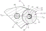
FIG. 3 is a perspective view of a cutting tool according to some embodiments of the present invention;
FIG. 4 is a top view of the cutting tool shown in FIG. 3;
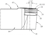
FIG. 5 is an exploded perspective view of the cutting tool shown in FIG. 3;
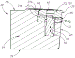
FIG. 6 is a cross-sectional view of the cutting tool shown in FIG. 5 taken along line VI-VI;
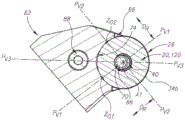
FIG. 7 is a cross-sectional view of the cutting tool shown in FIG. 6 taken along line VII-VII;
FIG. 8 is a side view of the cutting tool shown in FIG. 3;
FIG. 9 is a front view of the cutting tool shown in FIG. 3;
FIG. 10 is a cross-sectional view of the cutting tool shown in FIG. 5 taken along line X-X; and
fig. 11 is a cross-sectional view of the cutting tool shown in fig. 6 taken along line XI-XI.
Detailed Description
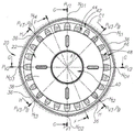
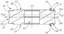
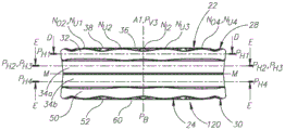
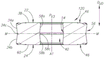
The present invention relates to an indexable cutting insert 20,120 as shown in fig. 1A-1C and 2A-2C having opposing upper and lower end surfaces 22, 24 with a continuous peripheral side surface 26 and a central axis a1 extending therebetween.
Upper and lower peripheries 28 and 30 are respectively formed at the intersections of the peripheral side surface 26 and the upper and lower end surfaces 22 and 24.
In some embodiments of the present invention, the cutting insert 20,120 may be indexable about a central axis a 1.
In some embodiments of the present invention, the cutting insert 20,120 may preferably be made of a shape pressed and sintered cemented carbide (e.g., tungsten carbide), and may be coated or uncoated.
In the first aspect of the invention, the peripheral side surface 26 includes a continuous upper relief surface 32 adjacent the upper peripheral edge 28, and a continuous upper abutment surface 34a spaced from the upper peripheral edge 28.
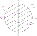
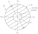
In a first aspect of the present invention, as shown in fig. 1D and 2D, the upper relief surface 32 is in a first horizontal plane P perpendicular to the central axis a1H1 is non-circular in cross-section, and as shown in fig. 1E and 2E, the upper abutment surface 34a is on a second horizontal plane P that is perpendicular to the central axis a1H2 is circular in cross section.
It should be appreciated that the non-circularity of the upper relief surface 32 in fig. 1D and 2D has been exaggerated to provide an improved understanding of the present invention.
Further, in the first aspect of the present invention, N (N ≧ 2) upper cutting edges 36 are formed on the upper peripheral edge 28, wherein each upper cutting edge 36 is defined about a bisector plane P containing the central axis A1BExhibiting mirror symmetry.
As shown in fig. 1C and 2C, in a side view of the cutting insert 20,120, each upper cutting edge 36 is non-linear.
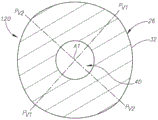
As shown in fig. 1B and 2B, in an end view of the cutting insert 20,120, the upper peripheral edge 28 is non-circular and exhibits N-fold rotational symmetry about the central axis a1, thus providing N index positions for the cutting insert 20, 120.
It should be appreciated that the non-circularity of the upper peripheral edge 28 in fig. 1B and 2B has been exaggerated to provide an improved understanding of the present invention.
Although the upper peripheral edge 28 is non-circular in end view of the cutting insert 20,120, it passes in a bisecting plane P as shown in FIG. 4BThe medium ramping cutting insert 20,120, the associated operative upper cutting edge 36, may exhibit a substantially constant upper radius of curvature RUTo engage a rotating workpiece, making the cutting insert 20,120 particularly suitable for the reshaping of railway car wheels.
As shown in FIGS. 1B and 2B, in an end view of the cutting insert 20,120, the first imaginary circle C1 may be at the N discrete radially outermost points NO1,NO2,N O3,NOAnd at 4 circumscribes the upper peripheral edge 28.
In some embodiments of the present invention, the upper radius of curvature RU may be greater than the radius of the first imaginary circle C1.
Additionally, in some embodiments of the present invention, the upper radius of curvature RU may be no more than 5% greater than the radius of the first imaginary circle C1.
Further, in some embodiments of the present invention, each upper cutting edge 36 may be at the N radially outermost points NO1,NO2,N O3,NO4 extend between two of them.
Still further, in some embodiments of the present invention, any two circumferentially adjacent upper cutting edges 36 may be at the N radially outermost points NO1,NO2,N O3,NO4 and both end points of each upper cutting edge 36 may merge with the N radially outermost points NO1,NO2,N O3,NO4 coincide.
When considering the cutting insert 20 in the first embodiment of the present invention, as shown in fig. 1C, N radially outermost points NO1,NO2,N O3,NO4 may be located closer to the second water than any other point on the upper periphery 28Plane PHAt 2.
By means of N radial outermost points NO1,NO2,N O3,NO4 are located closer to the second horizontal plane P than any other point on the upper peripheral edge 28HAt 2, the height of each upper cutting edge 36 is such that it extends from each of its two end points towards its associated bisecting plane PBThe extension is increased so that the operative upper cutting edge 36 advantageously directs chips away from the rotating workpiece.
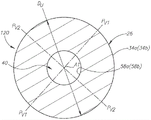
When considering the cutting insert 120 in the second embodiment of the present invention, as shown in fig. 2C, each upper cutting edge 36 may have a height lying further from the second horizontal plane P than any other point on said upper cutting edge 36HA plurality of discrete axially uppermost points N at 2 greater distancesU1,NU2,N U3,NU4。
In addition, in the second embodiment of the invention, two N of the axially uppermost points of each upper cutting edge 36U1,NU4 may be in contact with the N radially outermost points NO1,NO2,N O3,NO4 coincide.
As shown in fig. 2C, in a side view of the cutting edge 120, each upper cutting edge 36 may be wavy.
By having a plurality of discrete axially uppermost points NU1,NU2,N U3,NU4 and is a wave-shaped upper cutting edge 36, allows the cutting operation to be performed with a relatively low cutting force, and improves chip breaking and removal.
It should be appreciated that the description and claims may be applied to some embodiments of the invention, including both the first and second embodiments of the invention, except where specific reference is made to the first or second embodiment of the invention.
In some embodiments of the present invention, each upper cutting edge 36 may extend 360/N circumferentially along the upper periphery 28.
Additionally, in some embodiments of the present invention, the upper periphery 28 may have exactly four upper cutting edges 36, and N = 4.
As shown in fig. 1B and 2B, in an end view of the cutting insert 20,120, each upper cutting edge 36 may be non-linear.
In addition, as shown in fig. 1B and 2B, in an end view of the cutting insert 20,120, each upper cutting edge 36 may project outwardly with respect to the central axis a 1.
In some embodiments of the invention, any point on the upper peripheral edge 28 may be located further from the central axis a1 than any point on the upper abutment surface 34 a.
Additionally, in some embodiments of the present invention, the upper peripheral edge 28 may have N radially innermost points NI1,NI2,N I3,NI4, each contained in at least one bisecting plane PBIn (1).
As shown in fig. 1C,1E and 2C,2E, the upper abutment surface 34a may be conical, having an upper abutment diameter DUWhich decreases in a direction away from the upper end surface 22.
Additionally, as shown in fig. 1C and 2C, the upper end surface 22 may include a planar upper bearing surface 38, and the upper peripheral edge 28 may be located entirely closer to the second horizontal plane P than the upper bearing surface 38HAt 2.
In some embodiments of the present invention, a through bore 40 coaxial with the central axis a1 may open into the upper bearing surface 38.
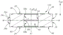
As shown in fig. 1A,1B and 2A,2B, the upper end surface 22 may include a continuous rake surface 42 adjacent the upper peripheral edge 28, and a chamfer 44 adjacent the upper bearing surface 38.
In some embodiments of the present invention, as shown in fig. 1F and 2F, the rake surface 42 may face the second horizontal plane PH2 extend radially inward and the ramp 44 may face a second horizontal plane PH2 extend radially outwards.
Additionally, in some embodiments of the present invention, as shown in fig. 1A,1B and 2A,2B, the ramp 44 may be interrupted by a plurality of circumferentially spaced apart projections 46.
Further, in some embodiments of the present invention, each protrusion 46 may be partially located on the rake surface 42.
As shown in fig. 1B and 2B, in an end view of the cutting insert 20,120, each projection 46 may include a convex radially outer portion 48.
In some embodiments of the present invention, the plurality of projections 46 may be greater in number than the plurality (N) of upper cutting edges 36.
Additionally, in some embodiments of the present invention, the plurality of projections 46 may be at least six times as many (N) as the plurality of upper cutting edges 36.
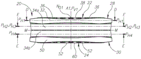
As shown in fig. 1C and 2C, the peripheral side surface 26 may include a continuous lower relief surface 50 adjacent the lower periphery 30, and a continuous lower abutment surface 34b spaced from the lower periphery 30.
In some embodiments of the present invention, the lower relief surface 50 may be identical to the upper relief surface 32, and the lower abutment surface 34b may be identical to the upper abutment surface 34 a.
Additionally, in some embodiments of the present invention, the lower peripheral edge 30 may be identical to the upper peripheral edge 28, having a plurality (N) of lower cutting edges 52 formed thereon, and the cutting insert 20,120 may be described as 'double-sided', having a total of N × 2 upper and lower cutting edges 36, 52.
Upon inverting the cutting insert 20,120 in one of the 'double-sided' cutting insert 20,120 and the bisector plane PB, the associated operative lower cutting edge 52 may exhibit a substantially constant lower radius of curvature R, as shown in FIG. 4LTo engage a rotating workpiece.
By tilting the 'double-sided' cutting insert 20,120, sufficient clearance is provided between the peripheral side surface 26 and the rotating workpiece.
In some embodiments of the invention, the lower radius of curvature RLMay be equal to the upper radius of curvature RU。
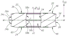
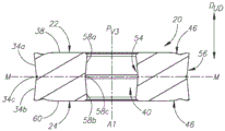
As shown in FIGS. 1F-1H and 2F-2H, a midplane M perpendicular to the central axis A1 may intersect the through hole 40.
In some embodiments of the invention, the midplane M may be located midway between the upper end surface 22 and the lower end surface 24.
Additionally, in some embodiments of the present invention, the via 40 may exhibit mirror symmetry about the midplane M.
Further, in some embodiments of the present invention, the peripheral side surface 26 may exhibit mirror symmetry about the midplane M.
Still further, in some embodiments of the present invention, the cutting insert 20,120 may exhibit mirror symmetry about the median plane M, and the upper relief surface 32 and the upper abutment surface 34a may be located between the upper end surface 22 and the median plane M.
In the second aspect of the invention, the through-hole 40 opens to both the upper end surface 22 and the lower end surface 24.
Further, in the second aspect of the invention, the through-hole 40 and the outer peripheral side surface 26 respectively have the upward-downward direction D with respect to the direction parallel to the central axis a1UDAn inner bottom cut 54 and an outer bottom cut 56.
Further, in the second aspect of the invention, as shown in fig. 1G and 2G, the inner bottom cutout 54 and the outer bottom cutout 56 are in mutually perpendicular first vertical planes P containing the central axis a1V1 and a second vertical plane PVVisible in the section taken in 2.
It should be appreciated that use of the term "undercut" throughout the description and claims refers to a recess or passage in which direction D is in an upward-downward directionUDA straight line extending from a given sub-surface of a recess or via intersects another sub-surface of the same recess or via.
As shown in fig. 1H and 2H, the inner undercut 54 and the outer undercut 56 may also lie within a plane that includes the central axis a1 and bisects a first vertical plane PV1 and a second vertical plane PV2 third vertical plane PVVisible in the section taken in 3.
In some embodiments of the present invention, the inner undercut 54 and the outer undercut 56 may be visible in cross-sections taken in any plane containing the central axis a 1.
As shown in fig. 1G and 2G, in a first vertical plane PV1 and a second vertical plane PV2, the through-hole 40 may accordingly be with respect to a second vertical plane PV2 and a first vertical plane PV1 exhibit mirror symmetry.
In some embodiments of the invention, the inner undercut 54 may be formed by the upper and lower opening surfaces 58a, 58b of the through-hole 40, and the upper and lower opening surfaces 58a, 58b may lie entirely on opposite sides of the midplane M.
Additionally, in some embodiments of the present invention, the upper and lower bore surfaces 58a, 58b may be spaced apart from one another by an intermediate bore surface 58 c.
As shown in fig. 1E and 2E, upper and lower bore surfaces 58a and 58b may be respectively at a third horizontal plane P that is perpendicular to central axis a1 H3 and a fourth level PH4 is circular in cross section.
In some embodiments of the invention, the second level PH2 and a third level P H3 may be coplanar.
In other embodiments of the invention (not shown), the first level PH1 and a third level P H3 may be coplanar.
As shown in fig. 1G and 2G, in a first vertical plane PV1 and a second vertical plane PV2, the upper opening surface 58a and the lower opening surface 58b may form a V-shape.
As shown in fig. 1G and 2G, in a first vertical plane PV1 and a second vertical plane PV2, the upper opening surface 58a and the lower opening surface 58b may form an outer opening obtuse angle α 1.
It should be appreciated that use of the term "external angle" throughout the description and claims refers to the angle between two surface members measured outside of the component on which these members are formed.
In some embodiments of the present invention, the opening obtuse angle α l may have a value equal to or greater than 160 °.
In addition, as shown in FIGS. 1G and 2G, in a first vertical plane PV1 and a second vertical plane PV2, the peripheral side surface 26 may be correspondingly about a second vertical plane PV2 and a first vertical plane PV1 exhibit mirror symmetry.
In some embodiments of the invention, the outer undercut 56 may be formed by the upper and lower abutment surfaces 34a, 34b, and the upper and lower abutment surfaces 34a, 34b may lie entirely on opposite sides of the midplane M.
Additionally, in some embodiments of the present invention, the upper and lower abutment surfaces 34a, 34b may be spaced apart by a middle peripheral surface 34 c.
As shown in fig. 1G and 2G, in a first vertical plane PV1 and a second vertical plane PV2, the upper and lower abutment surfaces 34a, 34b may form a V-shape.
In some embodiments of the present invention, upper and lower abutment surfaces 34a, 34b may form a V-shape in cross-section taken in any plane containing central axis a 1.
As shown in fig. 1G and 2G, in a first vertical plane PV1 and a second vertical plane PV2, the upper and lower abutment surfaces 34a, 34b may form an outer abutment obtuse angle α 2.
In some embodiments of the present invention, the abutment obtuse angle a2 may have a value equal to or greater than 160 °.
Additionally, in some embodiments of the present invention, both the upper and lower end surfaces 22, 24 may include planar upper and lower bearing surfaces 38, 60, respectively, and the through-hole 40 may open to the upper and lower bearing surfaces 38, 60.
As shown in fig. 1C and 2C, the upper and lower peripheral edges 28, 30 may lie entirely closer to the mid-plane M than the upper and lower bearing surfaces 38, 60, respectively.
In some embodiments of the present invention, upper bearing surface 38 and lower bearing surface 60 may be perpendicular to central axis a 1.
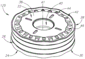
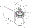
As shown in fig. 3-5, the second aspect of the present invention also relates to a cutting tool 62 having a blade holder 64 with an insert receiving pocket 66 formed in a forward end 68 thereof, and a cutting insert 20,120 removably secured in the insert receiving pocket 66 by a clamping member 70.
In a second aspect of the invention, the insert receiving pocket 66 has a seating surface 72 and a side wall 74 transverse thereto, with one of the upper and lower end surfaces 22, 24 facing the seating surface 72.
In some embodiments of the present invention, as shown in fig. 6, the seating surface 72 may be planar, and the midplane M may be parallel to the seating surface 72.
Additionally, in some embodiments of the present invention, only one of the upper cutting edge 36 and the lower cutting edge 52 may be operative, and the operative upper cutting edge 36 and or lower cutting edge 52 may be associated with one of the upper end surface 22 and the lower end surface 24 that faces away from the seat surface 72.
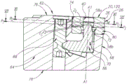
In a second aspect of the invention, as shown in fig. 6, the clamping member 70 is in at least one inner contact zone ZIIs in contact with only one of the upper opening surface 58a and the lower opening surface 58b, and at least one inner contact zone ZIEntirely between the midplane M and the seating surface 72.
As shown in fig. 7, in contact with at least one inner contact zone ZIInner contact plane P intersecting and perpendicular to the central axis A1IThe through-hole 40 may be circular in cross-section taken at (a).
Additionally, as shown in FIG. 7, the outer peripheral side surface 26 may be in the inner contact plane PIWithout making contact with the side wall 74 in the cross-section taken at (a).
In some embodiments of the invention, the gripping members 70 may be in a single inner contact zone ZIIs in contact with one of upper opening surface 58a and lower opening surface 58b and bisects first vertical plane PV1 and a second vertical plane PV2 third vertical plane P V3 can be in contact with a single inner contact zone ZIAnd the side wall 74.
As shown in fig. 6, in a third vertical plane PVIn the cross section taken in fig. 3, the upper opening surface 58a and the lower opening surface 58b may form a V shape.
In a third vertical plane P by means of an upper opening surface 58a and a lower opening surface 58b V3 is formed in a V-shape, applied by the clamping member 70 in the inner contact zone ZIClamping force F ofCIt may be advantageous to have a perpendicular component directed towards the seating surface 72, thus ensuring a firm and stable grip.
In some embodiments of the present invention, blade holder 64 may have opposing top and bottom holder surfaces 76, 78, and blade receiving pocket 66 may be located adjacent to top holder surface 76.
Additionally, in some embodiments of the present invention, the bottom frame surface 78 may be planar and the central axis a1 may intersect the bottom frame surface 78 and not be perpendicular thereto.
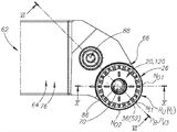
As shown in fig. 8 and 9, in side and front views of the cutting tool 62, the central axis a1 may form first and second inclination angles β 1 and β 2, respectively, with first and second imaginary straight lines L1 and L2 that are perpendicular to the bottom shelf surface 78.
In some embodiments of the present invention, the first and second inclination angles β 1 and β 2 may have an equal value between 1 degree and 3 degrees.
Additionally, in some embodiments of the present invention, the first and second ramping angles β 1, β 2 may exhibit a substantially constant radius of curvature R corresponding to the operative upper and lower cutting edges 36, 52U,RLThe degree of tilting of the cutting insert 20,120 required to engage a rotating workpiece.
In some embodiments of the invention, only one of the upper and lower abutment surfaces 34a, 34b may be at two spaced apart outer contact zones ZO1,ZO2 make contact with the side wall 74 of the insert receiving pocket 66 and two outer contact zones ZO1,ZO2 may lie entirely between the mid-plane M and the seating surface 72.
As shown in fig. 10 and 11, two outer contact zones ZO1,ZO2 may comprise a first outer contact zone ZO1 and a second outer contact zone ZO2 and the first vertical plane PV1 and a second vertical plane PV2 may correspondingly contact the first outer contact zone ZO1 and a second outer contact zone ZO2 intersect.
In a first vertical plane P by means of an upper abutment surface 34a and a lower abutment surface 34bV1 and a second vertical plane PV2 form a V-shape in cross-section directed away from the two outer contact zones Z of the side walls 74 of the insert receiving pocket 66O1,ZOReaction force F at 2RIt may be advantageous to have a perpendicular component directed away from the seating surface 72, thus ensuring a secure and stable grip.
As shown in fig. 11, in contact with two outer contact zones ZO1,ZO2 intersecting and perpendicular to the central axis a1OIn a cross-section taken at center, two outer contact zones ZO1,ZO2 may be located at an equal radial contact distance D from the central axis a1RTo (3).
In addition, as shown in FIG. 11, the peripheral side surface 26 may be at an outer contact plane POIs circular in cross-section, allowing the cutting insert 20,120 to be indexed about the central axis a1 without being removed from the insert receiving pocket 66.
Further, as shown in FIG. 11, the clip member 70 may be in an outer contact plane POWithout making contact with the through-hole 40 in the cross-section taken at (a).
In some embodiments of the invention, the inner contact plane PICan be located outside the contact plane POCloser to the seat surface 72, thus ensuring the clamping force FCAnd reaction force FRAny moment generated urges the cutting insert 20,120 toward the seating surface 72.
Visual indicia adjacent the upper and lower cutting edges 36, 52, as well as visual reference indicia on the blade holder 64, may be provided to assist an operator in indexing the cutting insert 20, 120.
In some embodiments of the present invention, a shim 80 having opposing top and bottom shim surfaces 82, 84 may be located between the cutting insert 20,120 and the seating surface 72.
As shown in fig. 5, one of the upper and lower end surfaces 22, 24 facing the seat surface 72 is in contact with the top gasket surface 82, and the bottom gasket surface 84 is in contact with the seat surface 72.
In some embodiments of the present invention, the clamping member 70 may be retained in the cartridge 64 in a non-threaded manner.
Additionally, in some embodiments of the present invention, the gripping member 70 may be in the form of a gripping rod 86 operatively connected to an actuating member 88.
As shown in fig. 6, the actuating member 88 may be threadably retained in the cartridge 64 and not in contact with the cutting blades 20, 120.
While the present invention has been described with reference to one or more particular embodiments, the description is intended to be illustrative in general, and is not to be construed as limiting the invention to the embodiments shown. It will be appreciated that various modifications may occur to those skilled in the art, which, although not specifically shown herein, are nevertheless within the scope of the present invention.
Claims (26)
1. An indexable cutting insert (20,120), comprising:
opposed upper (22) and lower (24) end surfaces with a continuous peripheral side surface (26) and a central axis (A1) extending therebetween,
an upper peripheral edge (28) and a lower peripheral edge (30) respectively formed at the intersection of the peripheral side surface (26) and the upper end surface (22) and the lower end surface (24), and
n upper cutting edges (36) formed on the upper peripheral edge (28), wherein N ≧ 2,
the outer peripheral side surface (26) includes:
a continuous upper relief surface (32) adjacent the upper peripheral edge (28) at a first horizontal plane (P) perpendicular to the central axis (A1)H1) Is non-circular in cross-section taken, an
A continuous upper abutment surface (34a) spaced from the upper peripheral edge (28) at a second horizontal plane (P) perpendicular to the central axis (A1)H2) Is circular in cross-section taken at (a),
wherein:
in both end and side views of the cutting insert (20,120), each upper cutting edge (36) is about a bisector plane (P) containing the central axis (A1)B) Exhibits mirror symmetry;
in an end view of the cutting insert (20,120), the upper peripheral edge (28) is non-circular and exhibits N-fold rotational symmetry about the central axis (A1); and
in a side view of the cutting insert (20,120), each upper cutting edge (36) is non-linear.
2. The cutting insert (20,120) according to claim 1, wherein each upper cutting edge (36) extends 360/N ° circumferentially along the upper peripheral edge (28).
3. The cutting insert (20,120) according to claim 1, wherein the upper abutment surface (34a) is conical with an upper abutment diameter (D) that decreases in a direction away from the upper end surface (22)U)。
4. The cutting insert (20,120) according to claim 1, wherein any point on the upper peripheral edge (28) may be located further from the central axis (a1) than any point on the upper abutment surface (34 a).
5. The cutting insert (20,120) according to claim 1, wherein:
the cutting insert (20,120) exhibits mirror symmetry about a midplane (M) perpendicular to the central axis (A1), an
The upper relief surface (32) and the upper abutment surface (34a) are located between the upper end surface (22) and the mid-plane (M).
6. The cutting insert (20,120) according to claim 1, wherein in an end view of the cutting insert (20,120), each upper cutting edge (36) is non-linear.
7. The cutting insert (20,120) according to claim 1, wherein in an end view of the cutting insert (20,120), each upper cutting edge (36) projects outwardly with respect to the central axis (a 1).
8. The cutting insert (20,120) according to claim 1, wherein:
the peripheral side surface (26) including a continuous lower relief surface (50) adjacent the lower periphery (30), and a continuous lower abutment surface (34b) spaced from the lower periphery (30); and
the lower relief surface (50) is identical to the upper relief surface (32); and
the lower abutment surface (34b) is identical to the upper abutment surface (34 a).
9. The cutting insert (20,120) according to claim 8, wherein in mutually perpendicular first perpendicular planes (P) containing the central axis (A1)V1) And a second vertical plane (P)V2) Wherein the upper abutment surface (34a) and the lower abutment surface (34b) form a V-shape.
10. The cutting insert (20,120) according to claim 9, wherein in the first perpendicular plane (P)V1) And said second vertical plane (P)V2) In a cross section taken in (c), the upper abutment surface (34a) and the lower abutment surface (34b) form an outer abutment obtuse angle (α 2).
11. The cutting insert (20,120) according to claim 8, wherein in a cross-section taken in any plane containing the central axis (a1), the upper abutment surface (34a) and the lower abutment surface (34b) form a V-shape.
12. The cutting insert (20,120) according to claim 1, wherein in an end view of the cutting insert (20,120), the first imaginary circle (C1) is at N discrete radially outermost points (N)O1,NO2,NO3,NO4) Circumscribing the upper peripheral edge (28).
13. The cutting insert (20,120) according to claim 12, wherein each upper cutting edge (36) is at N of the radially outermost points (N £ N)O1,NO2,NO3,NO4) Extend between two of them.
14. The cutting insert (20,120) according to claim 12, wherein any two circumferentially adjacent upper cutting edges (36) are at the N radially outermost points (N)O1,NO2,NO3,NO4) Is merged at one of them.
15. The cutting insert (20) according to claim 12, wherein N of the radially outermost points (N)O1,NO2,NO3,NO4) Closer to the second horizontal plane (P) than any other point on the upper periphery (28)H2)。
16. The cutting insert (120) according to claim 1, wherein each upper cutting edge (36) has a plurality of discrete axially uppermost points (Nu1, Nu2, Nu3, Nu4) located further from the second horizontal plane (P) than any other point on the upper cutting edge (36)H2) Further away.
17. The cutting insert (20,120) according to claim 1, wherein the upper peripheral edge (28) has exactly four upper cutting edges (36) and N = 4.
18. The cutting insert (20,120) according to claim 1, wherein:
the upper end surface (22) comprises a planar upper bearing surface (38), and
the upper peripheral edge (28) being located entirely closer to the second horizontal plane (P) than the upper bearing surface (38)H2) To (3).
19. The cutting insert (20,120) according to claim 18, wherein the cutting insert (20,120) comprises a through bore (40) coaxial with the central axis (a1) leading to the upper bearing surface (38).
20. The cutting insert (20,120) according to claim 18, wherein:
the upper end surface (22) including a continuous rake surface (42) adjacent the upper peripheral edge (28), and a chamfer (44) adjacent the upper bearing surface (38);
the rake face (42) faces the second horizontal plane (P)H2) Extends radially inward; and
the inclined surface (44) faces the second horizontal plane (P)H2) Extending radially outward.
21. The cutting insert (20,120) according to claim 20, wherein the chamfer (44) is interrupted by a plurality of circumferentially spaced projections (46).
22. The cutting insert (20,120) according to claim 21, wherein each protrusion (46) is located partially on the rake surface (42).
23. The cutting insert (20,120) according to claim 21, wherein in an end view of the cutting insert (20,120), each protrusion (46) comprises a convex radially outer portion (48).
24. The cutting insert (20,120) according to claim 21, wherein the plurality of projections (46) is greater in number than the plurality, N, of upper cutting edges (36).
25. The cutting insert (20,120) according to claim 21, wherein the plurality of projections (46) is at least six times greater in number than the plurality, N, of upper cutting edges (36).
26. An indexable cutting insert (20,120), comprising:
opposed upper (22) and lower (24) end surfaces with a continuous peripheral side surface (26) and a central axis (A1) extending therebetween,
an upper peripheral edge (28) and a lower peripheral edge (30) respectively formed at the intersection of the peripheral side surface (26) and the upper end surface (22) and the lower end surface (24), and
n upper cutting edges (36) formed on the upper peripheral edge (28), wherein N ≧ 2,
the outer peripheral side surface (26) includes:
a continuous upper relief surface (32) adjacent the upper peripheral edge (28) at a first horizontal plane (P) perpendicular to the central axis (A1)H1) Is in a section taken inCircular, and
a continuous upper abutment surface (34a) spaced from the upper peripheral edge (28) at a second horizontal plane (P) perpendicular to the central axis (A1)H2) Is circular in cross-section taken at (a),
wherein:
each upper cutting edge (36) extends 360/N DEG in the circumferential direction along the upper periphery (28) and about a bisector plane (P) containing the central axis (A1)B) Exhibits mirror symmetry;
in an end view of the cutting insert (20,120), the upper peripheral edge (28) is non-circular and exhibits N-fold rotational symmetry about the central axis (A1); and
in a side view of the cutting insert (20,120), each upper cutting edge (36) is non-linear.
Applications Claiming Priority (3)
| Application Number | Priority Date | Filing Date | Title |
|---|---|---|---|
| US201662290587P | 2016-02-03 | 2016-02-03 | |
| US62/290587 | 2016-02-03 | ||
| PCT/IL2017/050068 WO2017134650A1 (en) | 2016-02-03 | 2017-01-18 | Circular cutting insert having non-circular peripheral edge |
Publications (2)
| Publication Number | Publication Date |
|---|---|
| CN108602133A CN108602133A (en) | 2018-09-28 |
| CN108602133B true CN108602133B (en) | 2021-07-09 |
Family
ID=58108700
Family Applications (1)
| Application Number | Title | Priority Date | Filing Date |
|---|---|---|---|
| CN201780009561.XA Active CN108602133B (en) | 2016-02-03 | 2017-01-18 | Circular cutting insert having a non-circular periphery |
Country Status (11)
| Country | Link |
|---|---|
| US (1) | US10183333B2 (en) |
| EP (1) | EP3411172B1 (en) |
| JP (1) | JP7023235B2 (en) |
| KR (1) | KR102611090B1 (en) |
| CN (1) | CN108602133B (en) |
| BR (1) | BR112018015661B1 (en) |
| CA (1) | CA3012290A1 (en) |
| IL (1) | IL260312B (en) |
| RU (1) | RU2722360C2 (en) |
| TW (1) | TWI722094B (en) |
| WO (1) | WO2017134650A1 (en) |
Families Citing this family (6)
| Publication number | Priority date | Publication date | Assignee | Title |
|---|---|---|---|---|
| US10406608B2 (en) * | 2015-01-19 | 2019-09-10 | Kennametal Inc. | Cutting insert and pocket with uninterrupted and continuous seating surface perimeter |
| US10350689B2 (en) * | 2015-06-29 | 2019-07-16 | Mitsubishi Hitachi Tool Engineering, Ltd. | Double-sided circular cutting insert and indexable rotary cutting tool |
| US10646927B2 (en) * | 2018-02-19 | 2020-05-12 | Iscar, Ltd. | Round double-sided cutting insert having a peripheral surface provided with protruding indexing latches, insert holder therefor and cutting tool |
| EP3738697B1 (en) * | 2019-05-16 | 2023-02-22 | AB Sandvik Coromant | Turning tool for metal cutting |
| CN110860723B (en) * | 2019-12-05 | 2021-01-29 | 株洲钻石切削刀具股份有限公司 | Cutting blade for hole machining |
| CN113333799A (en) * | 2021-05-17 | 2021-09-03 | 贾中正 | High-efficiency cutting steel wheel rough turning circular blade with equally divided directional wavy cutting edge |
Family Cites Families (32)
| Publication number | Priority date | Publication date | Assignee | Title |
|---|---|---|---|---|
| US4274766A (en) * | 1979-11-28 | 1981-06-23 | The Valeron Corporation | Cutter assembly for broaching |
| SU1046026A1 (en) * | 1981-08-03 | 1983-10-07 | Предприятие П/Я М-5287 | Cutting polyhedral blade |
| US4606678A (en) | 1985-04-22 | 1986-08-19 | Gte Valeron Corporation | Circular chip control insert |
| SU1590202A1 (en) * | 1988-03-18 | 1990-09-07 | Всесоюзный заочный машиностроительный институт | Round cutting bit |
| GB9520436D0 (en) | 1995-10-06 | 1995-12-06 | Sandvik Ab | Cutting insert |
| WO1997027967A1 (en) | 1996-01-31 | 1997-08-07 | Widia Gmbh | Cutter insert for roughing and finishing |
| IL123685A (en) | 1998-03-16 | 2001-09-13 | Iscar Ltd | Modular cutting tool assembly |
| SE525913C2 (en) | 2002-12-20 | 2005-05-24 | Seco Tools Ab | Cutter, tool and method of mounting the insert where the insert can be oriented in the desired position |
| JP4762635B2 (en) * | 2005-08-05 | 2011-08-31 | 吉田プラ工業株式会社 | Airtight compact container |
| JP4752427B2 (en) | 2005-09-29 | 2011-08-17 | 株式会社タンガロイ | Throw-away insert for turning |
| JP4650272B2 (en) | 2006-01-11 | 2011-03-16 | 三菱マテリアル株式会社 | Round piece insert removable luffing end mill |
| SE0600338L (en) | 2006-02-15 | 2007-08-16 | Seco Tools Ab | Tool |
| DE102006023740B4 (en) | 2006-05-18 | 2017-05-11 | Kennametal Widia Produktions Gmbh & Co. Kg | Cutting insert and tool consisting of tool holder and cutting insert |
| DE102006025293C5 (en) | 2006-05-31 | 2010-12-23 | Kennametal Inc. | Method of machining a wheel |
| DE102008037915B3 (en) | 2008-08-14 | 2009-08-13 | Kennametal Inc. | Indexable insert |
| DE202008018646U1 (en) * | 2008-08-31 | 2017-03-24 | Iscar Ltd. | cutting insert |
| US9586264B2 (en) * | 2009-04-28 | 2017-03-07 | Kennametal Inc. | Double-sided cutting insert for drilling tool |
| KR101103216B1 (en) | 2009-05-19 | 2012-01-05 | 대구텍 유한회사 | Double-sided cutting insert having a circular shape and cutting tool using the same |
| CN102458732A (en) | 2009-06-02 | 2012-05-16 | 特固克有限会社 | Cutting insert and tool assembly comprising the same |
| US8388274B2 (en) | 2010-01-06 | 2013-03-05 | Kennametal Inc. | Round cutting insert with asymmetric chipbreaker feature |
| KR20120123463A (en) * | 2010-03-10 | 2012-11-08 | 가부시키가이샤 탕가로이 | Cutting Insert and Cutting Tool |
| RU2433390C1 (en) * | 2010-06-02 | 2011-11-10 | Институт машиноведения и металлургии Дальневосточного отделения Российской академии наук | Model of device for cooling fluid metals |
| AT12527U1 (en) * | 2011-02-24 | 2012-07-15 | Ceratizit Austria Gmbh | CUTTING INSERT FOR DISCONTINUING MACHINING |
| US8657539B2 (en) | 2011-03-28 | 2014-02-25 | Kennametal Inc. | Round cutting insert with reverse anti-rotation feature |
| JP5701385B2 (en) * | 2011-06-30 | 2015-04-15 | 京セラ株式会社 | Cutting insert, cutting tool, and method of manufacturing a cut product using the same |
| EP2596889B1 (en) * | 2011-11-23 | 2017-04-26 | Sandvik Intellectual Property AB | A cutting insert and a milling tool |
| SE536344C2 (en) * | 2012-01-30 | 2013-09-03 | Sandvik Intellectual Property | Milling tools and milling cutters where the cutting edge has an acute pitch |
| US8858130B2 (en) | 2012-04-24 | 2014-10-14 | Kennametal Inc. | Indexable circular cutting insert |
| CN104321155B (en) * | 2012-05-30 | 2016-08-24 | 京瓷株式会社 | Cutting insert, cutting element and be cut the manufacture method of machining object |
| US9283626B2 (en) * | 2012-09-25 | 2016-03-15 | Kennametal Inc. | Double-sided cutting inserts with anti-rotation features |
| RU134466U1 (en) * | 2013-02-21 | 2013-11-20 | Федеральное государственное бюджетное образовательное учреждение высшего профессионального образования "Комсомольский-на-Амуре государственный технический университет" | WHEELED WHEEL PLATE PLATE |
| CN104475827B (en) * | 2014-11-20 | 2017-04-05 | 厦门金鹭特种合金有限公司 | A kind of four width fist shape swords layering drilling special blade |
-
2016
- 2016-12-05 US US15/368,999 patent/US10183333B2/en active Active
-
2017
- 2017-01-17 TW TW106101470A patent/TWI722094B/en active
- 2017-01-18 CN CN201780009561.XA patent/CN108602133B/en active Active
- 2017-01-18 KR KR1020187021750A patent/KR102611090B1/en active IP Right Grant
- 2017-01-18 WO PCT/IL2017/050068 patent/WO2017134650A1/en active Application Filing
- 2017-01-18 CA CA3012290A patent/CA3012290A1/en active Pending
- 2017-01-18 EP EP17706900.2A patent/EP3411172B1/en active Active
- 2017-01-18 BR BR112018015661-2A patent/BR112018015661B1/en active IP Right Grant
- 2017-01-18 RU RU2018131346A patent/RU2722360C2/en active
- 2017-01-18 JP JP2018539326A patent/JP7023235B2/en active Active
-
2018
- 2018-06-27 IL IL260312A patent/IL260312B/en unknown
Also Published As
| Publication number | Publication date |
|---|---|
| TWI722094B (en) | 2021-03-21 |
| IL260312B (en) | 2021-10-31 |
| KR20180111820A (en) | 2018-10-11 |
| RU2722360C2 (en) | 2020-05-29 |
| JP2019508268A (en) | 2019-03-28 |
| JP7023235B2 (en) | 2022-02-21 |
| EP3411172B1 (en) | 2024-04-24 |
| CA3012290A1 (en) | 2017-08-10 |
| RU2018131346A3 (en) | 2020-04-16 |
| US20170216932A1 (en) | 2017-08-03 |
| TW201728390A (en) | 2017-08-16 |
| US10183333B2 (en) | 2019-01-22 |
| WO2017134650A1 (en) | 2017-08-10 |
| BR112018015661B1 (en) | 2022-05-31 |
| KR102611090B1 (en) | 2023-12-08 |
| EP3411172A1 (en) | 2018-12-12 |
| CN108602133A (en) | 2018-09-28 |
| IL260312A (en) | 2018-08-30 |
| RU2018131346A (en) | 2020-03-03 |
| BR112018015661A2 (en) | 2018-12-18 |
Similar Documents
| Publication | Publication Date | Title |
|---|---|---|
| CN108602133B (en) | Circular cutting insert having a non-circular periphery | |
| US10005132B2 (en) | Cutting tool and cutting insert having exactly three cutting portions therefor | |
| EP2978552B1 (en) | Rhombus-shaped indexable cutting insert and cutting tool | |
| US7905687B2 (en) | Cutting insert, tool holder, and related method | |
| JPH01115504A (en) | Tool holder for cutting insert | |
| US10384278B2 (en) | Square-shaped cutting insert having curved secondary and corner cutting edges, and rotary cutting tool | |
| EP3266547A1 (en) | Cutting insert and cutting edge-replaceable rotary cutting tool | |
| JP3769020B2 (en) | Cutting insert | |
| EP3600734B1 (en) | Blade-shaped cutting insert and cutting tool therefor | |
| US10035199B2 (en) | Cutting tool and triangular-shaped indexable cutting insert therefor | |
| US10632548B2 (en) | Triangular-shaped indexable cutting insert having recessed side surfaces and rotary cutting tool | |
| WO2018079491A1 (en) | Cutting insert, cutting tool, and manufacturing method for cut machined workpieces | |
| CN110582366B (en) | Cutting insert and cutting tool having different rectangular faces with raised and lowered corners |
Legal Events
| Date | Code | Title | Description |
|---|---|---|---|
| PB01 | Publication | ||
| PB01 | Publication | ||
| SE01 | Entry into force of request for substantive examination | ||
| SE01 | Entry into force of request for substantive examination | ||
| GR01 | Patent grant | ||
| GR01 | Patent grant |