The application is a divisional application, and the application number of the original application is as follows: 2017101686591, filing date: 2017-03-21, the name of invention creation is: a Teflon tubule cutting device and a method.
Disclosure of Invention
Aiming at the prior art, the technical problem to be solved by the invention is to provide a Teflon tubule cutting device, which can effectively improve the length precision of a cut pipe, has good incision quality, and reduces or even eliminates the bending or flattening condition of the pipe.
In order to solve the technical problem, the invention provides a Teflon tubule cutting device which comprises a base, a cooling water tank, a conveying mechanism, a clamping mechanism, a cutting driving mechanism, a supporting frame, an output mechanism, a rack and a collecting box, wherein the supporting frame is provided with at least 2 supporting columns; the cooling water tank, the conveying mechanism, the clamping mechanism, the cutting driving mechanism and the output mechanism are respectively arranged on a base, the cutting mechanism is arranged on the cutting driving mechanism, the supporting frame is arranged on the rack, the base is fixedly arranged on the supporting column, an inlet of the output mechanism is communicated with an outlet of the clamping mechanism, and the collecting box is placed in the rack; the Teflon tubules penetrate through the cooling water tank and are inserted into the conveying mechanism, the conveying mechanism conveys the Teflon tubules with fixed lengths into the clamping mechanism and clamps the Teflon tubules, the cutting driving mechanism drives the cutting mechanism to cut off the Teflon tubules in the clamping mechanism, and the output mechanism outputs the cut-off Teflon tubules into the collection box; the conveying mechanism comprises a conveying motor, a conveying motor mounting plate, a driving wheel pipe conveying assembly and a driven wheel pipe conveying assembly, the conveying motor is mounted on the conveying motor mounting plate, the conveying motor mounting plate and the driving wheel pipe conveying assembly are respectively mounted on the base, the driven wheel pipe conveying assembly is mounted on the driving wheel pipe conveying assembly, and an output shaft of the conveying motor is in driving connection with the driving wheel pipe conveying assembly; the driving wheel pipe conveying assembly comprises a first synchronous wheel, a second synchronous wheel, a synchronous belt, a first driving wheel, a second belt, a first pin shaft, a second pin shaft and a driving wheel mounting block, wherein the driving wheel mounting block is mounted on the base; the cutting mechanism comprises a base plate, a cutting motor mounting plate, a first belt pulley, a second belt pulley, a first belt, a rotating shaft mounting seat and a cutting piece, wherein the rotating shaft is rotatably mounted on the rotating shaft mounting seat, the cutting motor mounting plate and the rotating shaft mounting seat are respectively mounted on the base plate, the cutting motor is mounted on the cutting motor mounting plate, the first belt pulley is mounted on an output shaft of the cutting motor, the second belt pulley is mounted at one end of the rotating shaft, the first belt pulley is in transmission connection with the first belt pulley and the second belt pulley, and the cutting piece is fixedly mounted on the rotating shaft.
The cutting driving mechanism comprises a linear motor, a linear motor mounting plate, a sliding block and a guide rail, wherein the linear motor is mounted on the linear motor mounting plate, the linear motor mounting plate and the guide rail are respectively mounted on a base, the sliding block is mounted on a base plate, the base plate is fixedly connected with an output shaft of the linear motor, and the sliding block is connected with the guide rail in a sliding manner.
Compared with the prior art, the invention adopts the technical scheme that the Teflon tubules penetrate through the cooling water tank and are inserted into the conveying mechanism, the conveying mechanism conveys the Teflon tubules with fixed length into the clamping mechanism and clamps the Teflon tubules, the cutting driving mechanism drives the cutting mechanism to cut off the Teflon tubules in the clamping mechanism, and the output mechanism outputs the cut-off Teflon tubules into the collection box. The invention can effectively improve the length precision of the cut pipe, has good incision quality, and reduces or even eliminates the bending or flattening condition of the pipe.
Drawings
FIG. 1 is a perspective view of an embodiment of the present invention;
FIG. 2 is a perspective view of a combination of a base, a cooling water tank, a conveying mechanism, a clamping mechanism, a cutting driving mechanism and an output mechanism according to a first embodiment of the present invention;
FIG. 3 is a perspective view of a base and support frame combination according to a first embodiment of the present invention;
FIG. 4 is a perspective expanded view of FIG. 2 with the base and output mechanism removed;
FIG. 5 is a perspective view of a conveyor motor, a conveyor motor mounting plate, and a driving tube conveying assembly according to a first embodiment of the present invention;
FIG. 6 is a perspective expanded view of a driven roller tube assembly according to a first embodiment of the present invention;
FIG. 7 is a perspective view of a combination of a gripper mechanism and an output mechanism according to a first embodiment of the present invention;
FIG. 8 is a perspective expanded view of FIG. 7;
FIG. 9 is a perspective view of a cutting mechanism according to a first embodiment of the present invention;
fig. 10 is a perspective view of a clamping mechanism according to a second embodiment of the present invention;
FIG. 11 is a perspective expanded view of FIG. 10;
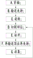
FIG. 12 is a flow chart of a method for precisely cutting a Teflon tubule according to the present invention.
The names of the components in the figure are as follows:
1-a base;
2-a cooling water tank;
3, a conveying mechanism;
31-a conveying motor;
32-conveying motor mounting plate;
33-driving the tube conveying assembly;
3301 — first synchronizing wheel;
3302 — second synchronizing wheel;
3303-synchronous belt;
3304 — first drive wheel;
3305 — second drive wheel;
3306 — second belt;
3307 — first pin;
3308 — second pin;
3309 — driving wheel mounting block;
3310-third driven wheel;
3311 — first tensioning wheel;
34-a driven wheel tube-in-tube assembly;
341-first driven wheel;
342-a second driven wheel;
343-third belt;
344 — driven wheel mounting block;
345 — a fourth driven wheel;
346 — second tensioning wheel;
4, a clamping mechanism;
41-finger cylinder;
42-finger cylinder mounting seat;
43-a clamping plate;
431-circular arc groove;
432-a gap;
44-a main clamping block;
45-auxiliary clamping block;
46-a main clamping mounting block;
5, a cutting mechanism;
51, a backing plate;
52-a cutting motor;
53-cutting the motor mounting plate;
54 — a first pulley;
55-a second pulley;
56 — a first belt;
57-a rotating shaft;
58-rotating shaft mounting base;
59-cutting the slices;
6-a cutting driving mechanism;
61-linear motor;
62-linear motor mounting plate;
63-a slide block;
64-a guide rail;
7-a support frame;
71-a support column;
72-a top plate;
73-a base plate;
8, an output mechanism;
81-casing;
82, receiving a material pipe;
83-material receiving pipe support frame;
84-telescopic pipes;
10, a frame;
30-Teflon tubules.
Detailed Description
The invention is further described with reference to the following description and embodiments in conjunction with the accompanying drawings.
The invention relates to a Teflon tubule cutting device, which comprises the following implementation modes:
as shown in fig. 1, a teflon tubule cutting device comprises a base 1, a cooling water tank 2, a conveying mechanism 3, a clamping mechanism 4, a cutting mechanism 5, a cutting driving mechanism 6, a supporting frame 7, an output mechanism 8, a frame 10 and a collecting box, wherein the supporting frame 7 is provided with at least 2 supporting columns 71; the cooling water tank 2, the conveying mechanism 3, the clamping mechanism 4, the cutting driving mechanism 6 and the output mechanism 8 are respectively and fixedly arranged on the base 1, the cutting mechanism 5 is fixedly arranged on the cutting driving mechanism 6, the supporting frame 7 is fixedly arranged on the rack 10, the base 1 is fixedly arranged on the supporting column 71, an inlet of the output mechanism 8 is communicated with an outlet of the clamping mechanism 4, and the collecting box is placed in the rack 10; the Teflon tubule 30 passes through the cooling water tank 2 and is inserted into the conveying mechanism 3, the conveying mechanism 3 conveys the Teflon tubule 30 with fixed length into the clamping mechanism 4 and is clamped, the cutting driving mechanism 6 drives the cutting mechanism 5 to cut off the Teflon tubule 30 in the clamping mechanism 4, and the output mechanism 8 outputs the cut-off Teflon tubule 30 to the collecting box.
Specifically, as shown in fig. 2, 4, 5, and 6, the cooling water tank 2 is fixedly mounted on the base 1, and the cooling water tank 2 can lower the temperature of the teflon thin tube 30, so that the teflon thin tube 30 becomes harder. The conveying mechanism 3 comprises a conveying motor 31, a conveying motor mounting plate 32, a driving wheel pipe conveying assembly 33 and a driven wheel pipe conveying assembly 34, the conveying motor 31 is fixedly mounted on the conveying motor mounting plate 32, the conveying motor mounting plate 32 and the driving wheel pipe conveying assembly 33 are respectively and fixedly mounted on the base 1, the driven wheel pipe conveying assembly 34 is fixedly mounted on the driving wheel pipe conveying assembly 33, an output shaft of the conveying motor 31 is in driving connection with the driving wheel pipe conveying assembly 33, and the conveying motor 31 adopts a servo motor. The driving wheel pipe conveying assembly 33 comprises a first synchronizing wheel 3301, a second synchronizing wheel 3302, a synchronizing belt 3303, a first driving wheel 3304, a second driving wheel 3305, 2 second belts 3306, a first pin 3307, a second pin 3308, a driving wheel mounting block 3309, the driving wheel mounting block 3309 is fixedly installed on the base 1, the first pin 3307 passes through the lower end of the driving wheel mounting block 3309 and is fixedly connected with the output shaft of the conveying motor 31, the second pin 3308 passes through the upper end of the driving wheel mounting block 3309 and is rotatably connected therewith, the first pin 3307 is rotatably connected with the driving wheel mounting block 3309, the first synchronizing wheel 3301 is fixedly installed at one end of the first pin 3307, the second synchronizing wheel 3302 is fixedly installed at one end of the second pin 3308, the synchronizing belt 3303 is in belt transmission connection with the first synchronizing wheel 3301 and the second synchronizing wheel 3302, the first driving wheel 3304 is fixedly installed at the other end of the first pin 3307, the second driving wheel 3305 is fixedly installed at the other end of the second pin 3308, the second belt 3306 is in belt transmission connection with the first pin 3307 and the second pin 3308. The capstan tube assembly 33 further comprises 4 third driven wheels 3310, a first tensioning wheel 3311, 4 third driven wheels 3310 rotatably mounted in a line on the outer side of the capstan mounting block 3309, a first tensioning wheel 3311 rotatably mounted on the inner side of the capstan mounting block 3309, and a first tensioning wheel 3311 for tensioning 2 second belts 3306. The driven wheel pipe-feeding assembly 34 comprises a first driven wheel 341, a second driven wheel 342, 2 third belts 343 and a driven wheel mounting block 344, wherein the driven wheel mounting block 344 is fixedly mounted on the base 1, the first driven wheel 341 is rotatably mounted at the lower end of the driven wheel mounting block 344, the second driven wheel 342 is rotatably mounted at the upper end of the driven wheel mounting block 344, and the third belts 343 are in belt transmission connection with the first driven wheel 341 and the second driven wheel 342. The driven wheel pipe-feeding assembly 34 further comprises 4 fourth driven wheels 345 and a second tensioning wheel 346, wherein the 4 fourth driven wheels 345 are arranged in a straight line and rotatably mounted on the inner side edge close to the driven wheel mounting block 344, the second tensioning wheel 346 is rotatably mounted on the outer side edge close to the driven wheel mounting block 344, and the second tensioning wheel 346 is used for tensioning 2 third belts 343. The second belt 3306 and the third belt 343 are both circular belts made of rubber. The distance between the driving wheel mounting block 3309 and the driven wheel mounting block 344 is adjusted, so that the space enclosed by the 2 second belts 3306 and the 2 third belts 343 can just elastically accommodate the lower teflon tubule 30, and the teflon tubule 30 is clamped by the 2 second belts 3306 and the 2 third belts 343 in 4 directions of the outer circle, and the clamping mode can reduce or even eliminate the condition that the pipe is bent or flattened.
Specifically, as shown in fig. 2, 4, 7, and 8, the clamping mechanism 4 includes a finger cylinder 41, a finger cylinder mount 42, and a clamping plate 43; the front surface of the clamping plate 43 is provided with an arc-shaped groove 431 for clamping the Teflon tubule 30, the arc-shaped groove 431 is designed according to the pipe diameter of the Teflon tubule 30, and a soft material (such as rubber and the like) is arranged in the arc-shaped groove 431 for clamping the Teflon tubule 30 so as not to deform; the side surface of the clamping plate 43 is provided with notches 432 for cutting, and a plurality of notches 432 are uniformly designed according to the length of the cut teflon tubule 30, and the first embodiment of the invention is designed into 12 notches; the finger cylinder 41 is fixedly mounted on the finger cylinder mounting seat 42, the finger cylinder mounting seat 42 is fixedly mounted on the base 1, and the clamping plate 43 is fixedly mounted on two fingers of the finger cylinder 41. The front surfaces of the two clamping plates 43 are provided with the arc-shaped grooves 431, soft materials are arranged in the arc-shaped grooves 431 to clamp the Teflon tubules 30, and the Teflon tubules 30 are stressed in the outer circumferential direction, so that the Teflon tubules 30 can be firmly clamped without deforming, the condition that the pipes are bent or flattened can be eliminated by the clamping mode, and the clamping is reliable and firm.
Specifically, as shown in fig. 2, 4 and 9, the cutting mechanism 5 includes a backing plate 51, a cutting motor 52, a cutting motor mounting plate 53, a first belt pulley 54, a second belt pulley 55, a first belt 56, a rotating shaft 57, 2 rotating shaft mounting seats 58 and a plurality of cutting blades 59, wherein the number of the cutting blades 59 is 12 according to the number of the cutting at one time; two ends of a rotating shaft 57 are respectively rotatably mounted on 2 rotating shaft mounting seats 58, the cutting motor mounting plate 53 and the rotating shaft mounting seats 58 are respectively and fixedly mounted on the backing plate 51, the cutting motor 52 is fixedly mounted on the cutting motor mounting plate 53, the first belt pulley 54 is fixedly mounted on an output shaft of the cutting motor 52, the second belt pulley 55 is fixedly mounted at one end of the rotating shaft 57, the first belt 56 is in belt transmission connection with the first belt pulley 54 and the second belt pulley 55, and 12 cutting pieces 59 are uniformly and fixedly mounted on the rotating shaft 57. The cutting motor 52 is a speed-adjustable motor. The rotary cutting blade 59 vertically cuts the Teflon tubule 30 clamped by the two clamping plates 43, so that the cut is flat and good in quality.
Specifically, as shown in fig. 4, the cutting driving mechanism 6 includes a linear motor 61, a linear motor mounting plate 62, 4 sliding blocks 63, and 2 guide rails 64, the linear motor 61 is fixedly mounted on the linear motor mounting plate 62, the linear motor mounting plate 62 and the 2 guide rails 64 are respectively fixedly mounted on the base 1, the 4 sliding blocks 63 are respectively fixedly mounted on the backing plate 51, the backing plate 51 is fixedly connected with an output shaft of the linear motor 61, and the 4 sliding blocks 63 are respectively slidably connected with the 2 guide rails 64. The linear motor 61 is a through type stepping linear motor.
Specifically, as shown in fig. 3, the supporting frame 7 includes 4 supporting columns 71, a top plate 72 and a bottom plate 73, the top plate 72 is fixedly mounted on the 4 supporting columns 71, the 4 supporting columns 71 are fixedly mounted on the bottom plate 73, and the bottom plate 73 is fixedly mounted on the rack 10.
Specifically, as shown in fig. 2, 7 and 8, the output mechanism 8 includes a sleeve 81, a material receiving pipe 82, a material receiving pipe support frame 83 and an extension pipe 84, the sleeve 81 is fixedly mounted on the finger cylinder mounting seat 42, the material receiving pipe support frame 83 is fixedly mounted on the base 1, the sleeve 81, the material receiving pipe 82 and the extension pipe 84 are sequentially communicated, one end of the sleeve 81 is communicated with an outlet of the clamping plate 43, the other end of the sleeve 81 is communicated with the material receiving pipe 82, and the material receiving pipe 82 is communicated with the extension pipe 84. In order to make the cut teflon thin tube 30 enter the collection box more smoothly, a vacuum pump can be added at the tail end of the extension tube 84, and negative pressure is formed in the extension tube 84 to suck the cut teflon thin tube 30.
The invention relates to a second embodiment of a Teflon tubule cutting device:
as shown in fig. 10 and 11, the second embodiment is substantially the same as the first embodiment, except that the clamping mechanism 4 is different, the clamping mechanism 4 of the second embodiment includes a main clamping block 44, a plurality of auxiliary clamping blocks 45 are arranged on the front surface of the main clamping block 44, circular arc-shaped grooves 431 for clamping the teflon tubules 30 are arranged on the front surfaces of the main clamping block 44 and the auxiliary clamping blocks 45, notches 432 for cutting are arranged on the side surfaces of the main clamping block 44, the auxiliary clamping blocks 45 and the notches 432 are designed according to the length of the cut teflon tubules 30, the number of the auxiliary clamping blocks 45 and the notches 432 can be uniformly designed, and the second embodiment of the invention is designed to be 12; the main clamping block 44 is fixedly mounted on the base 1 by a main clamping mounting block 46.
The invention also comprises a control system which is used for controlling the work of the conveying motor 31, the finger air cylinder 41, the cutting motor 52 and the linear motor 61.
As shown in fig. 12, the invention further provides a method for cutting the teflon tubule, which comprises the following steps:
A. inserting: the head of the Teflon thin tube 30 penetrates through the cooling water tank 2 and is inserted into the conveying mechanism 3;
B. conveying and clamping: the conveying mechanism 3 conveys the Teflon tubules 30 with fixed length into the clamping mechanism 4 and clamps the tubules;
C. rotating: the cutting mechanism 5 works and rotates;
D. cutting and returning: the cutting driving mechanism 6 works to drive the cutting mechanism 5 to move forwards until the clamping mechanism 4 cuts off the Teflon tubule 30 and returns;
E. loosening: the clamping mechanism 4 works to loosen the clamped Teflon tubule 30;
F. and (5) conveying, ejecting and re-clamping: the conveying mechanism 3 works again to convey the Teflon thin tubes 30 with fixed lengths into the clamping mechanism 4, the upward conveyed Teflon thin tubes 30 push the cut Teflon thin tubes 30 upward to enter the output mechanism 8, and the clamping mechanism 4 works again to clamp the Teflon thin tubes 30;
G. collecting: the output mechanism 8 outputs the cut teflon tubule 30 into the collection box;
and D, returning to the step D, and repeating the cutting.
Specifically, step a. interspersing: the head of the teflon thin tube 30 is inserted between the second belt 3306 and the third belt 343 through the cooling water tank 2 and clamped.
Specifically, step B includes the following substeps:
B1. the conveying motor 31 drives the second belt 3306 to rotate through belt transmission;
B2. the second belt 3306 drives the third belt 343 to convey the fixed-length teflon tubule 30 upwards together into the two clamping plates 43 through the teflon tubule 30;
B3. the finger cylinder 41 works to drive the two clamping plates 43 to clamp the Teflon tubule 30.
Specifically, step c. rotate: the cutting motor 52 drives the rotating shaft 57 to rotate through belt transmission, and the rotating shaft 57 drives the cutting blade 59 to rotate together.
Specifically, step D includes the following substeps:
D1. the linear motor 61 drives the rotating cutting blade 59 to move forwards through the slide block guide rail to the notch 432 to cut off the Teflon tubule 30;
D2. after cutting, the linear motor 61 carries the rotating cutting blade 59 to return.
Specifically, step e. unclamp: the finger cylinder 41 is operated and returned to drive the two clamping plates 43 to release the Teflon tubule 30.
Specifically, step F includes the following substeps:
F1. the conveying motor 31 works again to drive the second belt 3306 to rotate through belt transmission;
F2. the second belt 3306 drives the third belt 343 to convey the fixed-length teflon tubule 30 upwards together into the two clamping plates 43 through the teflon tubule 30;
F3. the upward conveyed teflon thin tube 30 pushes the cut teflon thin tube 30 upward to enter the material receiving tube 82;
F4. the finger cylinder 41 operates again to drive the two clamping plates 43 to clamp the Teflon tubule 30.
Specifically, step g. output: the cut teflon thin tube 30 in the material receiving tube 82 falls into the collection box through the telescopic tube 84 under the action of gravity; or the cut teflon thin tube 30 in the material receiving pipe 82 falls into the collection box through the telescopic pipe 84 under the action of the negative pressure suction of the vacuum pump.
The working principle of the Teflon tubule cutting equipment provided by the invention is as follows: the head of the teflon thin tube 30 penetrates through the cooling water tank 2 and is inserted between the second belt 3306 and the third belt 343 and clamped; the conveying motor 31 rotates to drive the first synchronizing wheel 3301 and the first driving wheel 3304 to rotate simultaneously, the first synchronizing wheel 3301 drives the second synchronizing wheel 3302 to rotate together through the synchronizing belt 3303, the second synchronizing wheel 3302 drives the second driving wheel 3305 to rotate together, so that the first driving wheel 3304 and the second driving wheel 3305 rotate simultaneously to drive 2 second belts 3306 to move upwards simultaneously, the 2 second belts 3306 drive 2 third belts 343 to convey the teflon tubules 30 clamped therein upwards together through friction force to enter the two clamping plates 43, the conveying length is fixed, and the finger cylinder 41 operates to drive the two clamping plates 43 to clamp the teflon tubules 30; the cutting motor 52 works and rotates to drive the first belt pulley 54 to rotate, the first belt pulley 54 drives the second belt pulley 55 to rotate through the first belt 56, and the second belt pulley 55 drives the plurality of cutting blades 59 to rotate together through the rotating shaft 57; when the linear motor 61 works, the plurality of rotary cutting blades 59 are driven by the backing plate 51 to move forwards along the guide rail 64 to the gap 432 to cut off the Teflon tubule 30, and after the cutting is finished, the linear motor 61 works again to bring the rotary cutting blades 59 to return together; the finger cylinder 41 works and returns to drive the two clamping plates 43 to loosen the Teflon tubule 30; the conveying motor 31 works again to rotate to drive the first synchronous wheel 3301 and the first driving wheel 3304 to rotate simultaneously, the first synchronous wheel 3301 drives the second synchronous wheel 3302 to rotate together through the synchronous belt 3303, the second synchronous wheel 3302 drives the second driving wheel 3305 to rotate together, so that the first driving wheel 3304 and the second driving wheel 3305 rotate simultaneously to drive 2 second belts 3306 to move upwards simultaneously, the 2 second belts 3306 drive 2 third belts 343 to convey the teflon tubules 30 clamped therein upwards together through friction force to enter the two clamping plates 43, the conveying length is fixed, the teflon tubules 30 conveyed upwards push out the cut teflon tubules 30 upwards to enter the material receiving pipe 82, and the finger cylinder 41 works again to drive the two clamping plates 43 to clamp the teflon tubules 30; the cut-off teflon thin tube 30 in the material receiving pipe 82 falls into the collection box through the extension tube 84 under the action of gravity, or the cut-off teflon thin tube 30 in the material receiving pipe 82 falls into the collection box through the extension tube 84 under the action of negative pressure suction of the vacuum pump.
The invention has the advantages that the Teflon tubule 30 is inserted into the conveying mechanism 3 through the cooling water tank 2, the conveying mechanism 3 conveys the Teflon tubule 30 with fixed length into the clamping mechanism 4 and clamps the Teflon tubule, the cutting driving mechanism 6 drives the cutting mechanism 5 to cut off the Teflon tubule 30 in the clamping mechanism 4, and the output mechanism 8 outputs the cut-off Teflon tubule 30 to the collection box. The invention can effectively improve the length precision of the cut pipe, has good incision quality, and reduces or even eliminates the bending or flattening condition of the pipe.
Compared with the prior art, the invention has the beneficial effects that:
1. the Teflon tubules 30 are clamped by 4 circular belts on the outer circle in four directions to be conveyed upwards, and because the circular belts made of rubber are stressed in the four directions and are soft, the Teflon tubules 30 cannot deform, bend or flatten, and the clamping mode can reduce or even eliminate the bending or flattening condition of the tube;
2. the front surfaces of the two clamping plates 43 are provided with the arc-shaped grooves 431, soft materials are arranged in the arc-shaped grooves 431 to clamp the Teflon tubules 30, and the Teflon tubules 30 are stressed in the outer circumferential direction, so that the Teflon tubules 30 can be firmly clamped without being deformed, the condition that the pipes are bent or flattened can be eliminated by the clamping mode, and the clamping is reliable and firm;
3. rotatory cutting piece 59 vertical cut is by the teflon tubule 30 of two grip blocks 43 centre grippings, can not produce horizontal pulling force to teflon tubule 30 when adopting this cutting mode cutting, and the incision that cuts out is level and smooth, and the incision is of high quality.
The foregoing is a more detailed description of the invention in connection with specific preferred embodiments and it is not intended that the invention be limited to these specific details. For those skilled in the art to which the invention pertains, several simple deductions or substitutions can be made without departing from the spirit of the invention, and all shall be considered as belonging to the protection scope of the invention.