CN108555130B - Steel sheet punching and deburring machining process - Google Patents
Steel sheet punching and deburring machining process Download PDFInfo
- Publication number
- CN108555130B CN108555130B CN201810055820.9A CN201810055820A CN108555130B CN 108555130 B CN108555130 B CN 108555130B CN 201810055820 A CN201810055820 A CN 201810055820A CN 108555130 B CN108555130 B CN 108555130B
- Authority
- CN
- China
- Prior art keywords
- punching
- material belt
- deburring
- product
- steel sheet
- Prior art date
- Legal status (The legal status is an assumption and is not a legal conclusion. Google has not performed a legal analysis and makes no representation as to the accuracy of the status listed.)
- Active
Links
Images

Classifications
-
- B—PERFORMING OPERATIONS; TRANSPORTING
- B21—MECHANICAL METAL-WORKING WITHOUT ESSENTIALLY REMOVING MATERIAL; PUNCHING METAL
- B21D—WORKING OR PROCESSING OF SHEET METAL OR METAL TUBES, RODS OR PROFILES WITHOUT ESSENTIALLY REMOVING MATERIAL; PUNCHING METAL
- B21D35/00—Combined processes according to or processes combined with methods covered by groups B21D1/00 - B21D31/00
- B21D35/001—Shaping combined with punching, e.g. stamping and perforating
-
- B—PERFORMING OPERATIONS; TRANSPORTING
- B21—MECHANICAL METAL-WORKING WITHOUT ESSENTIALLY REMOVING MATERIAL; PUNCHING METAL
- B21D—WORKING OR PROCESSING OF SHEET METAL OR METAL TUBES, RODS OR PROFILES WITHOUT ESSENTIALLY REMOVING MATERIAL; PUNCHING METAL
- B21D28/00—Shaping by press-cutting; Perforating
- B21D28/02—Punching blanks or articles with or without obtaining scrap; Notching
- B21D28/04—Centering the work; Positioning the tools
-
- B—PERFORMING OPERATIONS; TRANSPORTING
- B21—MECHANICAL METAL-WORKING WITHOUT ESSENTIALLY REMOVING MATERIAL; PUNCHING METAL
- B21D—WORKING OR PROCESSING OF SHEET METAL OR METAL TUBES, RODS OR PROFILES WITHOUT ESSENTIALLY REMOVING MATERIAL; PUNCHING METAL
- B21D28/00—Shaping by press-cutting; Perforating
- B21D28/24—Perforating, i.e. punching holes
- B21D28/26—Perforating, i.e. punching holes in sheets or flat parts
Abstract
The invention discloses a steel sheet punching and deburring processing technology which comprises material preparation, first punching, first deburring, second punching, second deburring, third punching and finished product collection. The invention has simple structure and remarkable effect, can well remove burrs and acute angles of the steel sheet and avoid the damage or other adverse effects of the steel sheet with the burrs or the acute angles on the soft plate.
Description
Technical Field
The invention relates to a deburring processing technology, in particular to a steel sheet punching deburring processing technology.
Background
The production of the steel sheet processed by the traditional composite stamping die is to cut off waste materials of the appearance of the product at one time. However, as the gap burr in the upper and lower molds does not come out, it is inevitable. In the past, an etching process is used for solving the problem to replace a stamping process, but the etching process can only ensure no burr, but acute angles can occur, if the burr or the acute angles exist in a product, assembly combination of the product and other parts can be influenced when the product is assembled on a soft board, so that assembly failure is caused, and the problem of the acute angles is still a bottleneck of the process and cannot be solved.
Disclosure of Invention
The invention aims to provide a steel sheet punching and deburring processing technology to solve the technical problem in the background technology.
In order to achieve the purpose, the invention provides the following technical scheme:
a steel sheet punching and deburring processing technology comprises the following steps:
a) preparing materials: according to the use requirements of products, a laminating machine is used for laminating a conductive adhesive and a steel sheet after being heated by an upper roller and a lower roller to form a material belt;
b) punching: the material belt is conveyed to a punching hole through a conveying mechanism, and positioning holes are punched in the two sides of the material belt through a punching needle;
c) straightening: the material belt punched with the positioning holes is guided in the X-axis direction and the Y-axis direction through a guide needle;
d) first punching: conveying the material belt to a first cutting die position through a conveying mechanism, punching the shapes of two sides of a product through a first upper die head, and simultaneously removing punched waste materials;
e) first deburring: carrying out chamfering and deburring operation on the edge of the product through the edge chamfering block on the material belt subjected to the primary punching;
f) and (3) second stamping: conveying the material belt to a second cutting die position through a conveying mechanism, punching the third edge shape of the product through a second upper die punch, and simultaneously removing the cut waste;
g) and (3) deburring for the second time: performing chamfering and deburring operation on the edge of the product subjected to secondary punching through the chamfering block;
h) third-time punching: conveying the material belt to a third cutting die position through a conveying mechanism, punching the last edge of the product through a third upper die punch and removing the punched waste;
i) collecting finished products: and sticking the finished product by using a low-viscosity film adhesive tape and uniformly packaging in a roll shape.
The chamfering block is arranged on a lower die of the die and is a convex surface, an upper die corresponding to the lower die is a concave surface, an edge on one side of the top end of the chamfering block is a chamfer, and the chamfer angle of the chamfering block is 25-45 degrees.
The invention has the beneficial effects that: the edge at the top end of the chamfering block of the lower die is a chamfer, namely, in the working process, when the bottom end of a product is abutted to the chamfering position of the chamfering block, the upper die moves downwards to punch the steel sheet, one side of the bottom end of the steel sheet deforms due to punching, and burrs and acute angles at the bottom end of the steel sheet are removed.
Drawings
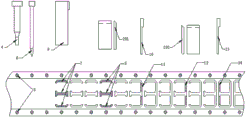
FIG. 1: a schematic operation diagram of a die when punching and deburring a steel sheet;
FIG. 2: a schematic diagram of a steel sheet punching and deburring processing process flow.
Detailed Description
The technical solution in the embodiments of the present invention will be clearly and completely described below with reference to the accompanying drawings in the embodiments of the present invention.
Specific example 1: referring to fig. 1 and 2, the invention provides a steel sheet punching and deburring processing technology, which comprises the following steps:
a) preparing materials: according to the use requirements of products, a laminating machine is used for laminating a conductive adhesive and a steel sheet after being heated by an upper roller and a lower roller to form a material belt;
b) punching, namely placing the attached material belt on an operation table, and punching positioning holes 5 in the material belt through a punching needle 4, wherein the positioning holes 5 are respectively arranged on two sides of the material belt;
c) straightening: the material belt punched with the positioning hole 5 in the previous step is subjected to X-axis and Y-axis direction correction through a correction needle 6;
d) first punching: the material belt is conveyed to the position of a first cutting die through a conveying mechanism, the shapes 7 of two sides of a product are punched through a first upper die head 8, and simultaneously, punched waste materials are removed;
e) first deburring: the material belt after the first punching is sent to the position of the chamfering block, the chamfering block 201 is arranged on a lower die of the die and is a convex surface, an upper die corresponding to the lower die is a concave surface, the edge on one side of the top end of the chamfering block 201 is a chamfer, the chamfer of the chamfering block is 42 degrees, the position of the bottom end 9 of the product 3 is abutted to the chamfer position of the chamfering block 201, then the upper die 1 moves downwards, the bottom surface of the extruded product is contacted with the working surface of the lower die 2, and therefore burrs and acute angles at the bottom end of the product 3 are removed; the chamfer size of the chamfering block 201 is adjusted according to the size and the requirement of the actually produced product;
f) and (3) second stamping: the material belt is conveyed to the position of a second cutting die through a conveying mechanism, and the third edge of the position of a punching-cut product on the material belt is punched through a second upper die punch 10, and meanwhile, the cut waste is removed;
g) and (3) deburring for the second time: punching the position of the third edge bottom end 12 of the product by the second punching material belt through the chamfering block 201, and performing chamfering and deburring operation;
h) third-time punching: conveying the material belt to a third cutting die position through a conveying mechanism, and punching a fourth side shape 14 of the product through a third upper die punch 13;
i) collecting finished products: and sticking the finished product by using a low-viscosity film adhesive tape and uniformly packaging in a roll shape.
The invention has the beneficial effects that: the edge at the top end of the chamfering block of the lower die is a chamfer, namely, in the working process, when the bottom end of a product is abutted to the chamfering position of the chamfering block, the upper die moves downwards to punch the steel sheet, one side of the bottom end of the steel sheet deforms due to punching, and burrs and acute angles at the bottom end of the steel sheet are removed.
It will be evident to those skilled in the art that the invention is not limited to the details of the foregoing illustrative embodiments, and that the present invention may be embodied in other specific forms without departing from the spirit or essential attributes thereof. The present embodiments are therefore to be considered in all respects as illustrative and not restrictive, the scope of the invention being indicated by the appended claims rather than by the foregoing description, and all changes which come within the meaning and range of equivalency of the claims are therefore intended to be embraced therein. Any reference sign in a claim should not be construed as limiting the claim concerned.
Furthermore, it should be understood that although the present description refers to embodiments, not every embodiment may contain only a single embodiment, and such description is for clarity only, and those skilled in the art should integrate the description, and the embodiments may be combined as appropriate to form other embodiments understood by those skilled in the art.
Claims (2)
1. A steel sheet punching and deburring processing technology is characterized by comprising the following steps:
a) preparing materials: according to the use requirements of products, a laminating machine is used for laminating a conductive adhesive and a steel sheet after being heated by an upper roller and a lower roller to form a material belt;
b) punching: the material belt is conveyed to a punching hole through a conveying mechanism, and positioning holes are punched in the two sides of the material belt through a punching needle;
c) straightening: the material belt punched with the positioning holes is guided in the X-axis direction and the Y-axis direction through a guide needle;
d) first punching: conveying the material belt to a first cutting die position through a conveying mechanism, punching the shapes of two sides of a product through a first upper die head, and simultaneously removing punched waste materials;
e) first deburring: carrying out chamfering and deburring operation on the edge of the product through the edge chamfering block on the material belt subjected to the primary punching;
f) and (3) second stamping: conveying the material belt to a second cutting die position through a conveying mechanism, punching the third edge shape of the product through a second upper die punch, and simultaneously removing the cut waste;
g) and (3) deburring for the second time: performing chamfering and deburring operation on the edge of the product subjected to secondary punching through the chamfering block;
h) third-time punching: conveying the material belt to a third cutting die position through a conveying mechanism, punching the last edge of the product through a third upper die punch and removing the punched waste;
i) collecting finished products: and sticking the finished product by using a low-viscosity film adhesive tape and uniformly packaging in a roll shape.
2. A steel sheet punching and deburring processing technology is characterized in that: the chamfering block is arranged on a lower die of the die and is a convex surface, an upper die corresponding to the lower die is a concave surface, an edge on one side of the top end of the chamfering block is a chamfer, and the chamfer angle of the chamfering block is 25-45 degrees.
Priority Applications (1)
| Application Number | Priority Date | Filing Date | Title |
|---|---|---|---|
| CN201810055820.9A CN108555130B (en) | 2018-01-20 | 2018-01-20 | Steel sheet punching and deburring machining process |
Applications Claiming Priority (1)
| Application Number | Priority Date | Filing Date | Title |
|---|---|---|---|
| CN201810055820.9A CN108555130B (en) | 2018-01-20 | 2018-01-20 | Steel sheet punching and deburring machining process |
Publications (2)
| Publication Number | Publication Date |
|---|---|
| CN108555130A CN108555130A (en) | 2018-09-21 |
| CN108555130B true CN108555130B (en) | 2020-08-04 |
Family
ID=63530933
Family Applications (1)
| Application Number | Title | Priority Date | Filing Date |
|---|---|---|---|
| CN201810055820.9A Active CN108555130B (en) | 2018-01-20 | 2018-01-20 | Steel sheet punching and deburring machining process |
Country Status (1)
| Country | Link |
|---|---|
| CN (1) | CN108555130B (en) |
Families Citing this family (2)
| Publication number | Priority date | Publication date | Assignee | Title |
|---|---|---|---|---|
| CN109773025B (en) * | 2018-12-29 | 2020-10-23 | 安徽省爱力特家电成套装备有限公司 | Automatic production system of oil tank truck pedestrian footpath board |
| CN111515074A (en) * | 2020-04-20 | 2020-08-11 | 深圳市满分爱科技有限公司 | Processing method of microporous atomization sheet |
Citations (6)
| Publication number | Priority date | Publication date | Assignee | Title |
|---|---|---|---|---|
| JPH08132149A (en) * | 1994-11-11 | 1996-05-28 | Mitsui High Tec Inc | Progressive die device |
| CN102430642A (en) * | 2011-09-19 | 2012-05-02 | 天津市津兆机电开发有限公司 | Molding process of progressive die of high temperature alloy sheet metal component with high flanging hole |
| CN103084469A (en) * | 2013-01-16 | 2013-05-08 | 温州恒田模具发展有限公司 | Producing method of snap spring |
| CN203370925U (en) * | 2013-08-01 | 2014-01-01 | 厦门锐腾电子科技有限公司 | Continuous die product chamfer device |
| CN204603050U (en) * | 2015-04-21 | 2015-09-02 | 浙江泰鸿机电有限公司 | For processing the progressive die of rear pillar side gas curtain guide plate |
| CN206882510U (en) * | 2017-04-25 | 2018-01-16 | 广东万和电气有限公司 | Burr removal mold for range hood |
-
2018
- 2018-01-20 CN CN201810055820.9A patent/CN108555130B/en active Active
Patent Citations (6)
| Publication number | Priority date | Publication date | Assignee | Title |
|---|---|---|---|---|
| JPH08132149A (en) * | 1994-11-11 | 1996-05-28 | Mitsui High Tec Inc | Progressive die device |
| CN102430642A (en) * | 2011-09-19 | 2012-05-02 | 天津市津兆机电开发有限公司 | Molding process of progressive die of high temperature alloy sheet metal component with high flanging hole |
| CN103084469A (en) * | 2013-01-16 | 2013-05-08 | 温州恒田模具发展有限公司 | Producing method of snap spring |
| CN203370925U (en) * | 2013-08-01 | 2014-01-01 | 厦门锐腾电子科技有限公司 | Continuous die product chamfer device |
| CN204603050U (en) * | 2015-04-21 | 2015-09-02 | 浙江泰鸿机电有限公司 | For processing the progressive die of rear pillar side gas curtain guide plate |
| CN206882510U (en) * | 2017-04-25 | 2018-01-16 | 广东万和电气有限公司 | Burr removal mold for range hood |
Also Published As
| Publication number | Publication date |
|---|---|
| CN108555130A (en) | 2018-09-21 |
Similar Documents
| Publication | Publication Date | Title |
|---|---|---|
| CN106881395A (en) | A kind of impulse- free robustness is punched baiting method and blanking equipment | |
| CN104244595A (en) | Method for manufacturing adhesive indentation reinforcing sheet | |
| CN108555130B (en) | Steel sheet punching and deburring machining process | |
| CN106424296A (en) | Hardware strip double-surface no-burr blanking process and no-burr blanking mold | |
| CN204263620U (en) | Be suitable for the steel bed die making hardening of soft package impression | |
| CN206253524U (en) | Framework punch-forming mold | |
| CN204448981U (en) | One is applicable to high-speed stamping die and cuts structure without the large euphotic belt essence in angle of collapsing | |
| CN114523031B (en) | Processing technology for cutting part without burr and product thereof | |
| CN105834294A (en) | Progressive die punching process cutter joint burr processing device and process | |
| CN204194573U (en) | Engine toothed chain carrier bar continuous stamping die | |
| CN104118005A (en) | Die cutting tool for battery tape and die cutting method thereof | |
| CN219819977U (en) | Product material punching die structure | |
| CN201823825U (en) | Double-station mould for battledore blanking | |
| CN111570624A (en) | Production process of metal parts and continuous die thereof | |
| CN107351183B (en) | Die-cut mould of zigzag plastic slab | |
| CN211539218U (en) | Accurate trimming die structure for aluminum foil material | |
| CN205551191U (en) | Novel knife -bending machine | |
| CN110978135A (en) | Composite die for punching and cutting plastic suction products | |
| CN109570342A (en) | A kind of Sheet Metal Forming Technology of the product with gap width-thickness ratio less than 1 | |
| CN110052533A (en) | Stamping die | |
| CN204602973U (en) | Diel | |
| CN211637953U (en) | Punching die for sheet parts | |
| CN206100428U (en) | Move iron from folding formula armature core | |
| CN112192658B (en) | Coiled material die cutting piece die cutting process with attaching identification line | |
| CN204367619U (en) | A kind of bamboo matter business card and punching tool thereof |
Legal Events
| Date | Code | Title | Description |
|---|---|---|---|
| PB01 | Publication | ||
| PB01 | Publication | ||
| SE01 | Entry into force of request for substantive examination | ||
| SE01 | Entry into force of request for substantive examination | ||
| GR01 | Patent grant | ||
| GR01 | Patent grant | ||
| CP01 | Change in the name or title of a patent holder |
Address after: No.62 Fumin South Road, Qiufu Road community, Dalang Town, Dongguan City, Guangdong Province Patentee after: Dongguan Liuchun Intelligent Technology Co.,Ltd. Address before: No.62 Fumin South Road, Qiufu Road community, Dalang Town, Dongguan City, Guangdong Province Patentee before: DONGGUAN LIUCHUN INTELLIGENT TECHNOLOGY Co.,Ltd. |
|
| CP01 | Change in the name or title of a patent holder |