CN108536188B - Automated adjustment of HVAC scheduling for resource conservation - Google Patents
Automated adjustment of HVAC scheduling for resource conservation Download PDFInfo
- Publication number
- CN108536188B CN108536188B CN201810238904.6A CN201810238904A CN108536188B CN 108536188 B CN108536188 B CN 108536188B CN 201810238904 A CN201810238904 A CN 201810238904A CN 108536188 B CN108536188 B CN 108536188B
- Authority
- CN
- China
- Prior art keywords
- schedule
- thermostat
- user
- home
- temperature
- Prior art date
- Legal status (The legal status is an assumption and is not a legal conclusion. Google has not performed a legal analysis and makes no representation as to the accuracy of the status listed.)
- Active
Links
Images


Classifications
-
- F—MECHANICAL ENGINEERING; LIGHTING; HEATING; WEAPONS; BLASTING
- F24—HEATING; RANGES; VENTILATING
- F24F—AIR-CONDITIONING; AIR-HUMIDIFICATION; VENTILATION; USE OF AIR CURRENTS FOR SCREENING
- F24F11/00—Control or safety arrangements
- F24F11/30—Control or safety arrangements for purposes related to the operation of the system, e.g. for safety or monitoring
- F24F11/46—Improving electric energy efficiency or saving
-
- F—MECHANICAL ENGINEERING; LIGHTING; HEATING; WEAPONS; BLASTING
- F24—HEATING; RANGES; VENTILATING
- F24F—AIR-CONDITIONING; AIR-HUMIDIFICATION; VENTILATION; USE OF AIR CURRENTS FOR SCREENING
- F24F11/00—Control or safety arrangements
- F24F11/50—Control or safety arrangements characterised by user interfaces or communication
- F24F11/52—Indication arrangements, e.g. displays
- F24F11/526—Indication arrangements, e.g. displays giving audible indications
-
- F—MECHANICAL ENGINEERING; LIGHTING; HEATING; WEAPONS; BLASTING
- F24—HEATING; RANGES; VENTILATING
- F24F—AIR-CONDITIONING; AIR-HUMIDIFICATION; VENTILATION; USE OF AIR CURRENTS FOR SCREENING
- F24F11/00—Control or safety arrangements
- F24F11/50—Control or safety arrangements characterised by user interfaces or communication
- F24F11/56—Remote control
- F24F11/58—Remote control using Internet communication
-
- F—MECHANICAL ENGINEERING; LIGHTING; HEATING; WEAPONS; BLASTING
- F24—HEATING; RANGES; VENTILATING
- F24F—AIR-CONDITIONING; AIR-HUMIDIFICATION; VENTILATION; USE OF AIR CURRENTS FOR SCREENING
- F24F11/00—Control or safety arrangements
- F24F11/62—Control or safety arrangements characterised by the type of control or by internal processing, e.g. using fuzzy logic, adaptive control or estimation of values
- F24F11/63—Electronic processing
-
- G—PHYSICS
- G05—CONTROLLING; REGULATING
- G05B—CONTROL OR REGULATING SYSTEMS IN GENERAL; FUNCTIONAL ELEMENTS OF SUCH SYSTEMS; MONITORING OR TESTING ARRANGEMENTS FOR SUCH SYSTEMS OR ELEMENTS
- G05B15/00—Systems controlled by a computer
- G05B15/02—Systems controlled by a computer electric
-
- G—PHYSICS
- G05—CONTROLLING; REGULATING
- G05D—SYSTEMS FOR CONTROLLING OR REGULATING NON-ELECTRIC VARIABLES
- G05D23/00—Control of temperature
- G05D23/19—Control of temperature characterised by the use of electric means
- G05D23/1917—Control of temperature characterised by the use of electric means using digital means
-
- F—MECHANICAL ENGINEERING; LIGHTING; HEATING; WEAPONS; BLASTING
- F24—HEATING; RANGES; VENTILATING
- F24F—AIR-CONDITIONING; AIR-HUMIDIFICATION; VENTILATION; USE OF AIR CURRENTS FOR SCREENING
- F24F11/00—Control or safety arrangements
- F24F11/50—Control or safety arrangements characterised by user interfaces or communication
- F24F11/52—Indication arrangements, e.g. displays
-
- F—MECHANICAL ENGINEERING; LIGHTING; HEATING; WEAPONS; BLASTING
- F24—HEATING; RANGES; VENTILATING
- F24F—AIR-CONDITIONING; AIR-HUMIDIFICATION; VENTILATION; USE OF AIR CURRENTS FOR SCREENING
- F24F11/00—Control or safety arrangements
- F24F11/50—Control or safety arrangements characterised by user interfaces or communication
- F24F11/61—Control or safety arrangements characterised by user interfaces or communication using timers
-
- F—MECHANICAL ENGINEERING; LIGHTING; HEATING; WEAPONS; BLASTING
- F24—HEATING; RANGES; VENTILATING
- F24F—AIR-CONDITIONING; AIR-HUMIDIFICATION; VENTILATION; USE OF AIR CURRENTS FOR SCREENING
- F24F11/00—Control or safety arrangements
- F24F11/62—Control or safety arrangements characterised by the type of control or by internal processing, e.g. using fuzzy logic, adaptive control or estimation of values
- F24F11/63—Electronic processing
- F24F11/64—Electronic processing using pre-stored data
-
- F—MECHANICAL ENGINEERING; LIGHTING; HEATING; WEAPONS; BLASTING
- F24—HEATING; RANGES; VENTILATING
- F24F—AIR-CONDITIONING; AIR-HUMIDIFICATION; VENTILATION; USE OF AIR CURRENTS FOR SCREENING
- F24F11/00—Control or safety arrangements
- F24F11/62—Control or safety arrangements characterised by the type of control or by internal processing, e.g. using fuzzy logic, adaptive control or estimation of values
- F24F11/63—Electronic processing
- F24F11/65—Electronic processing for selecting an operating mode
-
- F—MECHANICAL ENGINEERING; LIGHTING; HEATING; WEAPONS; BLASTING
- F24—HEATING; RANGES; VENTILATING
- F24F—AIR-CONDITIONING; AIR-HUMIDIFICATION; VENTILATION; USE OF AIR CURRENTS FOR SCREENING
- F24F2110/00—Control inputs relating to air properties
-
- F—MECHANICAL ENGINEERING; LIGHTING; HEATING; WEAPONS; BLASTING
- F24—HEATING; RANGES; VENTILATING
- F24F—AIR-CONDITIONING; AIR-HUMIDIFICATION; VENTILATION; USE OF AIR CURRENTS FOR SCREENING
- F24F2110/00—Control inputs relating to air properties
- F24F2110/10—Temperature
-
- F—MECHANICAL ENGINEERING; LIGHTING; HEATING; WEAPONS; BLASTING
- F24—HEATING; RANGES; VENTILATING
- F24F—AIR-CONDITIONING; AIR-HUMIDIFICATION; VENTILATION; USE OF AIR CURRENTS FOR SCREENING
- F24F2120/00—Control inputs relating to users or occupants
- F24F2120/20—Feedback from users
-
- F—MECHANICAL ENGINEERING; LIGHTING; HEATING; WEAPONS; BLASTING
- F24—HEATING; RANGES; VENTILATING
- F24F—AIR-CONDITIONING; AIR-HUMIDIFICATION; VENTILATION; USE OF AIR CURRENTS FOR SCREENING
- F24F2140/00—Control inputs relating to system states
- F24F2140/60—Energy consumption
Landscapes
- Engineering & Computer Science (AREA)
- General Engineering & Computer Science (AREA)
- Mechanical Engineering (AREA)
- Chemical & Material Sciences (AREA)
- Combustion & Propulsion (AREA)
- Physics & Mathematics (AREA)
- Signal Processing (AREA)
- Mathematical Physics (AREA)
- Fuzzy Systems (AREA)
- Human Computer Interaction (AREA)
- General Physics & Mathematics (AREA)
- Automation & Control Theory (AREA)
- Air Conditioning Control Device (AREA)
- Selective Calling Equipment (AREA)
- Remote Monitoring And Control Of Power-Distribution Networks (AREA)
- Supply And Distribution Of Alternating Current (AREA)
Abstract
The application relates to automated adjustment of HVAC scheduling for resource conservation. Apparatus, systems, methods, and related computer program products for optimizing a schedule of setpoint temperatures for use in control of an HVAC system. The disclosed system includes an energy management system that operates with an intelligent, networked thermostat located at a building. The thermostat includes a schedule for controlling a setpoint temperature of an HVAC system associated with a building in which the thermostat is located. The schedule of setpoint temperatures is continually adjusted by small, insignificant amounts so that the schedule migrates from the original schedule to the optimal schedule. The optimal schedule may be optimal in terms of energy consumption or some other aspect.
Description
Description of the cases
The application belongs to divisional application of Chinese invention patent application No.201480029114.7 with application date of 2014, 4, 8.
Cross Reference to Related Applications
This PCT application claims the benefit of priority from U.S. non-provisional application No.13/866,578 filed on 19/4/2013, the entire disclosure of which is incorporated herein by reference.
Technical Field
This patent specification relates to systems, apparatuses, methods and related computer program products for optimizing energy consumption of energy consuming devices. More specifically, this patent specification relates to techniques for reducing the amount of energy consumed by an HVAC system by performing small changes in temperature or in time to the schedule of temperature set points.
Background
As the number of people, the cost per energy unit, and the size and type of energy consuming devices used by consumers today increase, optimizing the use of energy by consumers is of increasing interest. While limited consumers use energy via various mechanisms, heating, ventilation, and air conditioning (HVAC) systems are good candidates to guide optimization efforts because they account for up to 40% of the energy consumption needs of average consumers in the united states. Thus, techniques for reducing the amount of energy consumed by such systems may advantageously result in tangible energy reductions and cost savings on an individual basis as well as significant reductions in overall energy demand.
In many modern HVAC systems, the HVAC system can be controlled according to a schedule of events. For example, the user may select a schedule (i.e., a temperature setpoint) of temperatures to which the user desires the HVAC system to control the indoor temperature. Such a schedule of temperature setpoints may define the temperature at which the HVAC system controls the indoor temperature of the building when a user is at home, out, sleeping, or awake. In other words, the indoor temperature can be controlled at any and all times of the day, whether residential or not.
While the scheduling of temperature set points by the HVAC system is generally satisfactory to users for the indoor temperature of the building at any given time, the temperature defined by the schedule does not correlate between user comfort and user discomfort. That is, there may be a difference between the temperature that the user sets comfortable and the temperature that the user actually feels comfortable. Known HVAC control systems typically strictly adhere to user requests for specific schedules of temperature set points without concern for such possible differences that result in potentially unnecessary energy consumption. In addition to strictly adhering to the temperature-wise characteristics of the schedule of temperature setpoints (e.g., adhering to the amount of temperature set by the user), typical HVAC control systems similarly strictly adhere to the temporal characteristics of their schedule of temperature setpoints (i.e., strictly adhering to the time of the temperature setpoints defined by the user). This inflexibility may lead to additional inefficiencies in various situations, such as when the real-time price of energy consumption changes during the day.
Disclosure of Invention
Embodiments of the present invention are directed to methods for optimizing energy consumption of an HVAC system. Such a method may include various operations. For example, the method can include identifying an original schedule of temperature setpoints that defines a plurality of temperature setpoints over a period of time. The method may further comprise: for each of a series of periodic time intervals, each relatively short compared to the overall optimization time period, starting with the original schedule, an incrementally adjusted version of the original schedule is generated, the incremental change resulting in less energy usage during one of the periodic time intervals than a previous one of the periodic time intervals. The method may further comprise: in each of a series of periodic time intervals, the HVAC system is controlled according to a progressively adjusted version of an original schedule generated for the periodic time interval.
In some embodiments, the method may further comprise: a subset of temperature setpoints within the original schedule of temperature setpoints is identified, the subset of temperature setpoints corresponding to a sub-interval of the time period defining the original schedule of temperature setpoints. In such embodiments, generating the incrementally adjusted version of the original schedule may include adjusting the subset of temperature setpoints differently than temperature setpoints other than those in the subset.
In some embodiments, the method may further comprise: a user selection of a current temperature setpoint that is different from a corresponding temperature setpoint of a progressively adjusted version of an original schedule generated for the periodic time interval is received during one of the periodic time intervals. Also, the method may further include: the HVAC system is controlled for at least a period of time within one of the periodic time intervals in accordance with a user selected current temperature setpoint, rather than the corresponding temperature setpoint of the incrementally adjusted version of the original schedule.
In some embodiments, the method may further comprise: within one of the periodic time intervals, a user modification to a temperature setpoint of a incrementally adjusted version of an original schedule generated for the one of the periodic time intervals is received. The method may also include incorporating the user modification in the incrementally adjusted version of the original schedule generated for one of the periodic time intervals, and controlling the HVAC system based on the user modification to the temperature setpoint of the incrementally adjusted version of the original schedule generated for the one of the periodic time intervals in the one of the periodic time intervals and in the series of time intervals.
Embodiments of the present invention are also directed to an intelligent networked thermostat for controlling and operating an HVAC system in a smart home environment. The thermostat may include various components, such as HVAC control circuitry operable to actuate one or more elements of the HVAC system. The thermostat may also include one or more sensors for measuring characteristics of the smart home environment. The thermostat may further include a processor coupled to the HVAC control circuitry and the one or more sensors and operable to cause the thermostat to perform various operations. Such operations may include identifying an original schedule of temperature set points. Such operations may further include: for each of a series of periodic time intervals, each relatively short compared to the overall optimization time period, starting with the original schedule, an incrementally adjusted version of the original schedule is generated, the incremental change resulting in less energy usage during one of the periodic time intervals than a previous one of the periodic time intervals. Such operations may further include: in each of a series of periodic time intervals, the HVAC system is controlled according to a progressively adjusted version of an original schedule generated for the periodic time interval.
In some embodiments describing a thermostat, generating an incrementally adjusted version of an original schedule may include: for each periodic time interval, the temperature of the originally scheduled at least one temperature setpoint is shifted in a direction that reduces energy consumption of the HVAC system.
Embodiments of the present invention are also directed to a tangible, non-transitory computer-readable storage medium having instructions that, when executed by a computer processor, cause the computer processor to perform various operations. Such operations may include, for example, identifying an original schedule of temperature setpoints that defines a plurality of temperature setpoints over a period of time. Such operations may further include: for each of a series of periodic time intervals, each relatively short compared to the overall optimization time period, starting with the original schedule, an incrementally adjusted version of the original schedule is generated, the incremental change resulting in less energy usage during one of the periodic time intervals than a previous one of the periodic time intervals. Such operations may further include: in each of a series of periodic time intervals, the HVAC system is controlled according to a progressively adjusted version of an original schedule generated for the periodic time interval.
In some embodiments, the storage medium may further include instructions to: the instructions, when executed by the computer processor, cause the computer processor to perform additional operations. Such additional operations may include, for example, identifying a first subset of temperature setpoints within the original schedule of temperature setpoints, the first subset of temperature setpoints corresponding to a first sub-interval of the time period defining the original schedule of temperature setpoints, the first sub-interval corresponding to a time period during which a building associated with the HVAC system is likely to be occupied. Also, a second subset of temperature setpoints within the original schedule of temperature setpoints is identified, the second subset of temperature setpoints corresponding to a second sub-interval of the time period during which the original schedule of temperature setpoints is defined, the second sub-interval corresponding to a time period during which a building associated with the HVAC system is unlikely to be occupied. In such embodiments, generating the incrementally adjusted version of the original schedule may include adjusting a first subset of the temperature setpoints differently than a second subset of the temperature setpoints, the second subset adjusted to reduce energy usage by a greater amount than that resulting from the adjustment made to the first subset.
Such additional operations may additionally or alternatively include, for example, identifying a first subset of temperature setpoints within the original schedule of temperature setpoints that corresponds to a first sub-interval of the time period that defines the original schedule of temperature setpoints. Such additional operations may also include identifying a second subset of temperature setpoints within the original schedule of temperature setpoints that corresponds to a second sub-interval of the time period that defines the original schedule of temperature setpoints. Such additional operations may further include identifying a third subset of temperature setpoints within the original schedule of temperature setpoints, the third subset of temperature setpoints corresponding to a third sub-interval of the time period defining the original schedule of temperature setpoints. In some embodiments, for a first set of a series of periodic time intervals, generating the incrementally adjusted version of the original schedule can include modifying temperature setpoints of a first subset of the temperature setpoints. For a second set of a series of periodic time intervals subsequent to the first set of periodic time intervals, generating the incrementally adjusted version of the original schedule can include modifying the temperature setpoints of the second subset of temperature setpoints while modifying the temperature setpoints of the first subset of temperature setpoints. For a third set of a series of periodic time intervals subsequent to the second set of periodic time intervals, generating the incrementally adjusted version of the original schedule can include modifying the temperature setpoints of the third subset of temperature setpoints while modifying the temperature setpoints of the first subset of temperature setpoints and the temperature setpoints of the second subset of temperature setpoints.
For a fuller understanding of the nature and advantages of embodiments of the present invention, reference should be made to the following detailed description and accompanying drawings. Other aspects, objects, and advantages of the invention will be apparent from the drawings and from the detailed description that follows. The scope of the invention will, however, be fully apparent from the content of the claims.
Drawings
FIG. 1 depicts a system for supplying, managing, and consuming energy, according to an embodiment.
FIG. 2 illustrates an example of a smart-home environment in which one or more of the devices, methods, systems, services and/or computer program products described further below can be employed.
Fig. 3A illustrates an example of general device components that may be included in an intelligent networked device, according to an embodiment.
FIG. 3B illustrates an intelligent networked device with a replaceable module and an docking station, in accordance with an embodiment.
Fig. 3C illustrates a connection port and a patch sensing circuit of an intelligent networking device, according to an embodiment.
Fig. 4 illustrates a network-level view of the extensible devices and service platforms with which the smart home of fig. 1 and/or 2 and/or the devices of fig. 3A-3C can be integrated.
FIG. 5 illustrates an abstract functional view of the extensible device and service platform of FIG. 4, according to an embodiment.
FIG. 6 is a block diagram of a special purpose computer system according to an embodiment.
FIG. 7 illustrates a process for implementing and managing a schedule optimizer, according to an embodiment.
Fig. 8 illustrates a process for identifying devices eligible for schedule optimization according to an embodiment.
FIG. 9 illustrates a process for generating, presenting, and implementing a schedule optimization process according to an embodiment.
FIG. 10 illustrates a process for optimizing an original schedule of setpoint temperatures in accordance with a first embodiment.
11A and 11B illustrate a process for optimizing an original schedule of setpoint temperatures according to a second embodiment.
Fig. 12A-12H illustrate adjustment of an original schedule of setpoint temperatures according to a scheduled setpoint optimization process, including three-phase modification of a schedule separated into three sub-intervals, according to an embodiment.
Fig. 13A illustrates the size of a progressive schedule adjustment over time in a three-stage schedule optimization without any user modification, according to an embodiment.
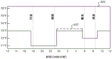
Fig. 13B illustrates the size of a progressive schedule adjustment over time in a three-stage schedule optimization with various user modifications, according to an embodiment.
Fig. 14A-14L illustrate a thermostat having a Graphical User Interface (GUI) for implementing a schedule optimization process, in accordance with various embodiments.
Detailed Description
Embodiments of the present invention are directed to methods for optimizing energy consumption of an HVAC system. The entities involved in many energy consumption systems typically include utility providers that provide electricity or other forms of energy from a power source (e.g., a generator) to individual homes or businesses. Individuals typically pay for the amount of energy they consume on a regular basis, such as monthly. In many embodiments, the energy management system is disposed between a utility provider and an individual. The energy management system may perform various roles, such as managing optimization of an individual's energy consumption, generating an optimized schedule of temperature setpoints based on an original schedule of temperature setpoints, sensed data (such as indoor temperatures, building occupancy, etc.), predicted data (such as expected outdoor temperatures), user-indicated preferences, and/or various additional or alternative data. Such optimized scheduling may then be implemented by the energy management system in order to effectively reduce and/or redistribute individual energy consumption as well as overall energy consumption.
An energy management system according to many embodiments includes an intelligent networked thermostat located at an individual's home or business. Such a thermostat may obtain various information about the home, such as the warmth retention characteristics of the home, the ability of the HVAC associated with the home to cool or heat the home, the likelihood of the home being occupied (via occupancy sensors that can establish a probability distribution of occupancy over a period of time), predicted weather, real-time occupancy, and so forth. Further, the thermostat may be programmed by its user, or may learn over a period of time its user's preferences and habits with respect to setting the scheduled temperature set point. In an exemplary embodiment, such a population of networked thermostats associated with respective populations of individual homes and businesses is configured to communicate with one or more central servers managed by one or more cloud service providers. Each networked thermostat is associated with one or more accounts managed by a cloud service provider and sends data back and forth between each networked thermostat and a central server as needed to provide various advantageous functions, such as facilitating remote control, reporting weather data, reporting HVAC control data and status information, and providing centralized and/or locally centralized control and data communication that facilitates performing the schedule optimization functions described herein.
It should be understood that while some embodiments herein may be particularly suitable and advantageous in business scenarios where (i) the cloud service provider associated with a population of networked thermostats is also the provider of the energy management system, (ii) the provider of the energy management system is a separate and distinct business entity from the utility, and (iii) the energy management system is provided as a value-added service to the utility, the scope of this specification is not limited in any way to such scenarios. In other applicable scenarios, all elements may be provided by a utility, for example. In other applicable scenarios, some elements can be provided by a utility, while other elements can be provided by a government agency or by various consortia of different cooperating enterprises or communities. Before a particular schedule is optimized, the energy management system can effectively predict how much energy a home is likely to consume given a particular schedule of setpoint temperatures, based on the amount of information the energy management system has about the home it is managing. Such information may be used for various purposes, including determining whether a home is a suitable candidate for schedule optimization. Once a particular home has been determined to be a suitable candidate for schedule optimization, some or all of the wealth of information may then be used to optimize the schedule of temperature setpoints for that particular home with heatstroke prevention as follows: this approach allows for a reduction and/or diversion of energy consumption and/or energy consumption costs without significant changes to the comfort of the occupants of the home. In some cases, such optimization may even persist with occupant comfort, while a continuous static schedule may result in significant discomfort.
The foregoing measures for such energy consumption prediction and management bring about a number of advantages as further described below. For example, this approach not only allows the energy management system to efficiently manage the energy consumption of multiple connected residences, but also allows the energy management system to intelligently select a subset of residences from a large pool that participate in the schedule optimization event. The physical characteristics of residences, the geographic characteristics of residences, and the habitual tendencies of the occupants of these residences vary widely across regions, and therefore the possible energy savings/transfers are also quite different. The energy management system disclosed herein can intelligently select participants in an energy conservation program to maximize efficiency and minimize costs including unnecessary distress to occupants. Various energy management systems are further described in U.S. application serial No.13/842,213 (reference No. nes0253-US), filed on 15/3/2013, the entire contents of which are incorporated herein by reference for all purposes.
Details of these and other embodiments are further disclosed herein, and can be understood further with reference to the accompanying drawings. Turning now to the drawings, FIG. 1 depicts a system 100 for supplying, managing, and consuming energy, according to an embodiment. The system 100 includes a plurality of power generators 110A-110N, a utility provider computing system 120, an energy management system 130, a communication network 140, a plurality of energy consumer residences 150A-150N, and a power distribution network 160.
The power generators 110A-110N are operable to generate electrical power or other types of energy (e.g., gas) using one or more of a variety of techniques known in the art. For example, the power generators 110A-110N may include hydro electric power generation systems, nuclear power plants, fossil fuel based power plants, solar power plants, wind power plants, gas treatment plants, and the like. The amount of power that can be generated at any given time may be limited to some maximum amount of power supplied as determined by the generators 110A-110N. Additionally, the power generators 110A-110N may be owned and managed by a utility provider implementing the utility provider computing system 120, or may be owned and managed by one or more third party entities that agree with the utility provider to provide resource energy to the utility provider's customers.
The utility provider computing system 120 is a computing system operable to communicate with one or more of the power generators 110A-110N, the energy management system 130, and, in some embodiments, the electronic systems in one or more of the residences 150A-150N. The utility provider associated with the utility provider's company system 120 typically manages the distribution of electricity from the electricity generators 110A-110N to the energy consumers at the residences 150A-150N. The management includes ensuring that power is successfully delivered from the power generators 110A-110N to the residences 150A-150N, monitoring an amount of energy consumption at each of the residences 150A-150N, and charging a fee from the occupants of the residences 150A-150N based on their respective monitored amounts of energy consumption. The utility provider computing system 120 may perform one or more of the operations described herein, and may include various computer processors, storage elements, communication mechanisms, and the like, as further described herein and as needed to facilitate the described operations.
The energy management system 130 is a computing system operable to intelligently and efficiently manage energy consumption at one or more of the residences 150A-150N while optionally providing reporting and control mechanisms to the utility provider computing system 120. The energy management system 130 is operable to communicate bi-directionally in real time with the electronic devices associated with the residences 150A-150N and with the utility provider computing system 120 via the network 150. In a particular embodiment, the energy management system 130 may operate to reduce the total amount of energy consumed at the residences 150A-150N in order to reduce the energy supply requirements of the power generators 110A-110N. Such a reduction may be achieved at one or more of various times. Such a reduction may be achieved, for example, at the beginning of a weather period that is relatively constant with respect to other weather periods (i.e., relatively small day-to-day temperature variations). In some environments, this may be the beginning of the spring or fall. However, in other environments, this may be at the beginning of the summer or winter months. Some environments may have relatively constant periods of weather throughout the year, in which case it may be desirable to perform schedule optimization only once or once a year to achieve energy reduction.
The residences 150A-150N are various buildings or enclosures associated with energy consumption. Buildings may span a variety of building types, such as private homes, houses, apartments, residential apartments, schools, commercial properties, single or multi-story office buildings, and/or manufacturing plants. The various examples described herein relate to buildings that are private residences in the form of houses, but the embodiments are not so limited as those skilled in the art will appreciate that the techniques described herein are equally applicable to other types of buildings. It should be understood that while some embodiments may be particularly advantageous for residential life scenarios, the scope of the present teachings is not so limited and may be equally advantageous in business environments, school environments, government building environments, sports or entertainment venues, and the like. Accordingly, while much of the following description is set forth in the context of a resident's life, it should be understood that this is done for clarity of description and not for limitation.
The residences 150A-150N typically include one or more energy consuming devices, which can be electrical energy consuming devices, such as televisions, microwave ovens, home audio equipment, heating/cooling systems, washing machines, dishwashers, and the like. Similarly, the energy consuming device can comprise one or more other types of energy consuming devices, such as a gas consuming device. For example, the residences 150A-150N may include natural gas (air/water/etc.) heaters, stoves, fireplaces, and the like. The houses 150A-150N in many embodiments include controlling the above-described energyOne or more control devices for energy consumption of one or more of the consumers. For example, it may comprise an intelligent networked thermostat operable to control the thermal environment of a residence. The thermostat may be considered part of the energy management system 130, as the various processes described subsequently herein may be performed by a computing system at the energy management system 130 or by the thermostat itself. Alternatively, the thermostat may be considered separate from the energy management system 130 in that it is in a remote geographic location relative to other components of the energy management system 130. In any case, the electronic devices associated with the residences 150A-150N may perform one or more of the operations described herein, and may include various computer processors, storage elements, communication mechanisms, and the like, as further described herein and as needed to facilitate the described operations. While most of the embodiments are set forth in the context of situations where it is desirable to reduce the temperature inside a building (e.g., during the hot summer season), similar principles apply (and are applied to the contrary) in situations where it is desirable to increase the temperature inside a building (e.g., during the cold winter season). For some embodiments, some or all of the intelligent networked thermostats may be functionally equivalent to NEST LEARNING available from Nest Labs, inc The same or similar.
The power distribution network 160 is any suitable network for transferring energy from one or more of the power generators 110A-110N to one or more of the residences 150A-150N. In the distribution network, the distribution network 160 may include various power lines, substations, pole-hanging transformers, and the like for transmitting power from the power generators 110A-110N to the residences 150A-150N as is well known in the art. In a gas distribution network, the power distribution network 160 may include various compressor stations, storage elements, piping, and the like for transporting natural or other types of energy-producing gas from the power generators 110A-110N (gas wells and/or processing plants in this embodiment) to the residences 150A-150N.
Fig. 2 illustrates an example of a smart-home environment 200 in which one or more of the devices, methods, systems, services and/or computer program products described further below can be employed. The depicted smart-home environment includes a building 250, which can include, for example, a house, an office building, a garage, or a mobile home. In some embodiments, building 250 may correspond to one of buildings 150A-150N described with reference to FIG. 1. In addition to the building 250, the smart-home environment 200 includes a network 262 and a remote server 264, which in one embodiment correspond to the network 140 and the energy management system 130 (FIG. 1), respectively. While the depicted building 250 includes various components and equipment as further described below, several components and equipment, such as the pool heater 214, the irrigation system 216, and the access equipment 266, can also be associated with (e.g., powered) the building 250 without being physically attached or disposed within or on the building 250.
The smart-home environment 200 includes a plurality of rooms 252 separated from one another at least in part via walls 254. The wall 254 can include an interior wall or an exterior wall. Each room can further include a floor 256 and a ceiling 258. The device can be mounted on, integrated with, and/or supported by a wall 254, floor 256, or ceiling 258. The various devices that may be included within the smart home environment 200 include intelligent multi-sensing networked devices that can be seamlessly integrated with each other and/or with a cloud-based server system to provide any of a variety of utilitarian smart home objectives. The intelligent multi-sensing networked thermostat 202 is capable of detecting environmental characteristics (e.g., temperature and/or humidity) and controlling a heating, ventilation, and air conditioning (HVAC) system 203. It should be appreciated that while control of an HVAC system is described herein, similar principles may be equally applicable to control other temperature/humidity control systems, such as a heating system, an air conditioning system, a humidity control system, or any combination thereof. The one or more intelligent networked multi-sensing hazard detection units 204 can detect the presence of hazardous materials and/or hazardous conditions (e.g., smoke, fire, or carbon monoxide) in the home environment. One or more intelligent multi-sensing networked entry interface devices 206, which can be referred to as "smart doorbells," can detect the entry or exit location of a person, control a living room function, notify the entry or exit of a person via audiovisual devices, or control settings on the security system (e.g., activate or deactivate the security system).
In some embodiments, the smart home may include at least one energy consumption meter 218, such as a smart meter. Energy consumption meter 218 monitors some or all of the energy (electricity, gas, etc.) consumed by equipment in and around building 250. The energy consumption meter 218 may display the amount of energy consumed in a given period of time on the surface of the meter 218. The given period may be, for example, seconds, minutes, hours, days, months, a time span less than a second, a time span greater than a month, or a time span between a second and a month. In some embodiments, energy consumption meters 218 may include communication capabilities (wired or wireless) that enable meters 218 to communicate various information, such as the amount of energy consumed in one or more given periods of time, the price of energy at any particular time or during any particular period of time, and the like. The communication capability may also enable the meter to receive various information. For example, the meter may receive instructions for controlling one or more devices in a smart home, such as the HVAC system 203, energy prices at any particular time or during any particular time period, and the like. To facilitate control of the devices in and around the building 250, the meters 218 may be wired or wirelessly connected to these devices.
Each of the plurality of intelligent multi-sensing networked wall lamp switches 208 is capable of detecting ambient lighting conditions, detecting room occupancy status, and controlling power and/or dimming status of one or more lamps. In some cases, the light switch 208 can further or alternatively control the power state or speed of a fan, such as a ceiling fan. Each of the plurality of intelligent multi-sensing networking wall plug interfaces 210 is capable of detecting occupancy of a room or enclosure and controlling power to one or more wall plugs (e.g., such that if no one is at home, no power is supplied to the plug). The smart home may further include a plurality of smart multi-sensing networked appliances 212, such as refrigerators, stoves and/or ovens, televisions, washing machines, dryers, lights (inside and/or outside of the building 250), stereos, intercom systems, garage door openers, floor fans, ceiling fans, whole house exhaust fans, wall air conditioners, pool heaters 214, irrigation systems 216, security systems, and the like. While the description of fig. 2 can identify specific sensors and functions associated with a specific device, it should be understood that any of a variety of sensors and functions (such as those described in this specification) can be integrated within a device.
In addition to containing processing and sensing capabilities, each device within the smart-home environment 200 is capable of data communication and data sharing with any other device within the smart-home environment 200 and any device outside of the smart-home environment 240, such as the access device 266 and/or the remote server 264. The device is capable of sending and receiving communications via any of a number of custom or standard wireless protocols (Wi-Fi, ZigBee, 6LoWPAN, IR, IEEE 802.11, IEEE 802.15.4, etc.) and/or any of custom or standard wired protocols (CAT6 ethernet, HomePlug, etc.). The wall plug 210 may function as a wireless or wired repeater and/or may be capable of functioning as a bridge between (i) devices plugged into an AC outlet and communicating using Homeplug or other power line protocols and (ii) devices that are not plugged into an AC outlet.
For example, a first device can communicate with a second device via wireless router 260. The device can further communicate with remote devices via a connection to a network, such as network 262. Through the network 262, the device is able to communicate with a central (i.e., remote) server or cloud computing system 264. The remote server or cloud computing system 264 can be associated with a manufacturer, a support entity, or a service provider associated with the device. In one embodiment, the user is able to use the device itself to contact customer support without using other communication means, such as a telephone or an internet-connected computer.
The network connection of the device can further allow the user to interact with the device even if the user is not in the vicinity of the device. For example, a user can use a computer (e.g., a desktop, laptop, or tablet computer) or other portable electronic device (e.g., a smartphone) 266 to communicate with a device (e.g., the thermostat 202). The web page or software application can be configured to receive communications from a user and control the device based on the communications, and/or present information to the user regarding the operation of the device. For example, when the portable electronic device 266 is used to interact with the thermostat 202, the user can view the thermostat's current setpoint temperature and adjust it using the portable electronic device 266. The user can be inside the building or outside the building during the telecommunication. Communication between the portable electronic device 266 and the thermostat 202 may be routed via the remote server 264 (e.g., when the portable electronic device 266 is remote from the building 250), or may be routed without the remote server 264 in some embodiments.
The smart-home environment 200 can also include various non-communicating conventional appliances 240, such as legacy washers/dryers, refrigerators, and the like, which can be controlled via the wall plug interface 210, but in a conventional manner (on/off). The smart home can further include various partially communicating conventional appliances 242, such as an IR-controlled wall air conditioner or other IR-controlled device, which can be controlled by IR signals provided by the hazard detection unit 204 or the light switch 208, or in some embodiments, by communicating via the wall outlet interface 210 using a socket-based communication protocol, such as power line.
It should be appreciated that some or all of the components located inside and outside of building 250 may be considered part of energy management system 130, according to an embodiment. In general, devices or components that facilitate control of other energy consuming devices may be considered part of energy management system 130. For example, the thermostat 202 and access device 266 can be part of the energy management system 130, while energy consuming components such as the HVAC203, pool heater 214, and legacy appliances 240 can be considered external to the energy management system 130 because they include energy consuming elements that can be controlled by the thermostat 202 and access device 266. However, in other examples, additional or alternative components of the smart home environment 200 may be considered part of the energy management system 130, such as the hazard detection unit 204, the entrance interface device 206, the light switch 208, the plug interface 210, and so forth, as it may provide monitoring (and/or control) functionality for the energy management system 130 to assist the system 130 in making intelligent energy management decisions. In other examples, all devices of the smart-home environment (except the remote server 264) may not be part of the energy management system 130, while one or more devices of the smart-home environment 200 may be slave devices that are remotely controlled by the energy management system 130 to perform monitoring and/or energy consumption tasks.
In a particular embodiment, the smart home 200 is an environment that includes a plurality of client devices and access devices that are all operable to communicate with each other and with devices or systems external to the smart home 200, such as the remote server 264. However, those skilled in the art will appreciate that such an environment would work equally well with fewer or greater numbers of components than the system shown in FIG. 2. One specific example of a smart home environment including various elements with different functions is described in detail in U.S. provisional application No.61/704,437 (reference No. nes0254-US), filed on 21/9/2012, the entire contents of which are hereby incorporated by reference for all purposes. Accordingly, the depiction of the smart-home environment 200 in FIG. 2 should be taken as illustrative in nature and not limiting the scope of the present teachings.
Fig. 3A illustrates an example of general device components that can be included in an intelligent networked device 300 (i.e., a "device"). Device 300 may be implemented as one or more of the various devices described with reference to fig. 2, such as thermostat 202, hazard detection unit 204, entry interface device 206, wall lamp switch 208, wall plug interface 210, and so forth. The following discussion mostly presents the device 300 as a thermostat 200, but it should be understood that the embodiments are not limited thereto. Each of one, more, or all of the devices 300 within the system of devices can include one or more sensors 302, a user interface component 304, a power source (e.g., including a power connection 306 and/or a battery 308), a communication component 310, a modular unit (e.g., including an expansion station 312 and a replaceable module 314), a smart component 316, and a tamper detection circuit 318. The particular sensors 302, user interface components 304, power configurations, communication components 310, modular units, smart components 316, and/or wired tamper detection circuitry 318 can be the same or similar between devices 300, or can vary depending on the type or model of device.
By way of example, but not by way of limitation, one or more sensors 302 in device 300 may be capable of detecting, for example, acceleration, temperature, humidity, moisture, power, proximity, external motion, device motion, acoustic signals, ultrasonic signals, optical signals, fire, smoke, carbon monoxide, Global Positioning Satellite (GPS) signals, or Radio Frequency (RF) or other electromagnetic signals or fields. Thus, for example, the sensors 302 can include temperature sensors, humidity sensors, hazard-related or other environmental sensors, accelerometers, microphones, optical sensors, or even cameras (e.g., charge-coupled devices or video cameras), active or passive radiation sensors, GPS receivers, or radio frequency identification detectors. Although fig. 3A illustrates an embodiment with a single sensor, many embodiments will include multiple sensors. In some cases, device 300 includes one or more primary sensors and one or more secondary sensors. The primary sensor can sense data focused on the core operation of the device (e.g., sensing temperature in a thermostat or sensing smoke in a smoke detector). The secondary sensor can sense other types of data (e.g., motion, light, or sound) that can be used for energy efficient purposes or for intelligent operation purposes. In some cases, the ordinary user may not even be aware of the presence of the secondary sensor.
One or more user interface components 304 in device 300 may be configured to present information to a user via a visual display (e.g., a thin film transistor display or an organic light emitting diode display) and/or audio speakers and/or some other communication medium. The user interface component 304 can also include one or more user input components for receiving information from a user, such as a touch screen, buttons, a scrolling component (e.g., a movable or virtual ring component), a microphone, or a camera (e.g., for detecting gestures). In one embodiment, the user interface component 304 comprises a click-to-rotate annular ring component, wherein a user can interact with the component by rotating the ring (e.g., to adjust a setting) and/or by clicking the ring inward (e.g., to select an adjusted setting or to select an option). In another embodiment, the user input component 304 includes a camera, enabling detection of gestures (e.g., to indicate that a power supply or warning state of the device is to be altered).
The power components in device 300 may include a power connection 306 and/or a local battery 308. For example, power connection 306 may connect device 300 to a power source such as a line voltage source. In some cases, the connection 306 to the AC power source may be used to repeatedly charge a (e.g., rechargeable) local battery 308 so that the battery 308 may later supply power when needed in the event of an AC power disconnection or other power deficiency.
The communication component 310 in the device 300 includes components that enable the device 300 to communicate with a central server, such as a remote server, or a remote device, such as another device 300 or a portable user device as described herein. By way of non-limiting example, the communications component 310 can allow the device 300 to perform communications simultaneously or sequentially using one or more wired or wireless communication technologies, such as Wi-Fi, ZigBee, 3G/4G wireless, IEEE 802.11, IEEE 802.15.4, 6-LO-PAN, Bluetooth, CAT6 wired Ethernet, HomePlug, or other power line communication methods, telephony, or fiber, by way of non-limiting example. The communication component 310 can include one or more wireless network cards, ethernet plugs, or other transceiver connections. In some embodiments, the communication component 310 facilitates communication with a central server to synchronize information between the device 300, the central server, and in some cases additional devices. Techniques for synchronizing data between these devices are further described in U.S. application No.13/624,892 (reference No. nes0231-US), filed on 9, 22, 2012, which is incorporated by reference herein for all purposes.
The modular units in the device 300 can include static physical connections as well as replaceable modules 314. Thus, the modular unit can provide the ability to upgrade the replaceable module 314 without requiring a complete reinstallation of the device 300 (e.g., to maintain wiring). The static physical connection can include an expansion station 312 (which may also be referred to as an interface box) that can be attached to the building structure. For example, the docking station 312 can be mounted to a wall via screws or glued to a ceiling via an adhesive. In some cases, the docking station 312 can extend through a portion of the building structure. For example, the docking station 312 can be connected to wiring behind the wall (e.g., to 120V line voltage wires) via holes made through the wall gypsum board. The docking station 312 can include circuitry such as the power connection circuit 306 and/or an AC to DC power circuit and prevent users from being exposed to high voltage wires. The docking station 312 may also or alternatively include circuitry for actuating (i.e., turning on and off) elements of an HVAC system, such as a heating unit (for heating the building structure), an air conditioning unit (for cooling the building structure), and/or a ventilation unit (for circulating air throughout the building structure). In some cases, the docking station 312 is specific to the type and model of equipment, such that, for example, a thermostat device includes a different docking station than a smoke detector device. In some cases, the docking station 312 can be shared among multiple types and/or models of devices 300.
The replaceable module 314 of the modular unit can include some or all of the sensors 302, processor, user interface components 304, battery 308, communication components 310, intelligence components 316, etc. of the device. The replaceable module 314 can be configured to attach to (e.g., plug in or connect to) the docking station 312. In some cases, a set of replaceable modules 314 are produced with capabilities, hardware, and/or software that vary between replaceable modules 314. Thus, a user can easily upgrade or replace their replaceable module 314 without having to replace all of the components or completely reinstall the device 300. For example, a user can start with an inexpensive device that includes a first replaceable module with limited intelligence and software capabilities. The user can then easily upgrade the device to include a more capable replaceable module. As another example, if a user has a model # 1 device in their basement, a model # 2 device in their living room, and upgrades their living room device to include a model #3 replaceable module, the user can move the model # 2 replaceable module to the basement to connect to an existing docking station. The model # 2 replaceable module may then, for example, begin an initialization process to facilitate identification of its new location (e.g., by requesting information from a user via a user interface).
The intelligent component 316 of the device can support one or more of a variety of different device functions. The intelligent component 316 generally includes one or more processors configured and programmed to perform and/or cause to be performed one or more of the advantageous functions described herein. The intelligence component 316 can be implemented in the form of: a general-purpose processor, special-purpose processor, or application-specific integrated circuit that executes computer code stored in local memory (e.g., flash memory, hard drive, random access memory), a combination thereof, and/or a processing platform that uses other types of hardware/firmware/software. Further, the smart component 316 can be implemented as a localized version or a peer of an algorithm executed or governed remotely by a central server or cloud-based system, such as by running a Java Virtual Machine (JVM) that executes instructions provided from a cloud server using asynchronous Javascript and xml (ajax) or similar protocols. By way of example, the intelligent component 316 can be configured to detect when a location (e.g., a house or room) is occupied, even including whether it is occupied by a particular person or a particular number and/or group of people (e.g., relative to one or more thresholds). Such detection may occur, for example, by analyzing microphone signals, detecting user activity (e.g., in front of the device), detecting opening and closing of a door or garage door, detecting wireless signals, detecting an IP address of a received signal, or detecting operation of one or more devices within a time window. The intelligent component 316 can include image recognition techniques for identifying a particular occupant or object.
In some cases, the intelligence component 316 can be configured to predict desired settings and/or implement those settings. For example, based on presence detection, the smart component 316 can adjust device settings to, for example, conserve power or comply with user preferences (e.g., general home preferences or user-specific preferences) when no one is at home or in a particular room. As another example, based on the detection of a particular person, animal, or object (e.g., a child, pet, or lost object), the smart component 316 can initiate an audiovisual indicator of where the person, animal, or object is, or can initiate an alert or security feature if an unidentified person is detected under certain conditions (e.g., at night or when lights are turned off). As another example, the intelligent component 316 can detect trends in user settings by hour, by week, or even by season and adjust the settings accordingly. For example, the intelligent component 316 can detect that a particular device was turned on every weekday at 6:30 am or that the device setting was gradually adjusted from a high setting to a low setting over the last three hours. The intelligent component 316 can then predict that the device is to be turned on every weekday at 6:30 am or that the settings should continue to gradually lower their settings over a longer period of time.
In some cases, the devices are able to interact with each other such that an event detected by a first device affects an action of a second device. For example, the first device can detect that a user has entered the garage (e.g., by detecting motion in the garage, detecting a change in light in the garage, or detecting opening of a door of the garage). The first device can communicate this information to the second device so that the second device can, for example, adjust an indoor temperature setting, a light setting, a music setting, and/or a safety warning setting. As another example, the first device can detect that a user is approaching the front door (e.g., by detecting motion or sudden light pattern changes). The first device can, for example, cause a general audio-visual signal to appear (e.g., such as a doorbell ring up) or cause a location-specific audio-visual signal to appear (e.g., to notify the presence of a visitor in a room in which the user lives).
The tamper detection circuit 318 may be part of the smart component 316 or separate from the smart component 316. Tamper detection circuitry 318 may include software and/or hardware operable to detect tampering with device 300. Tampering may include, for example, indicating a user attempting to remove an HVAC-controlled device 300 from the HVAC via a remote server, indicating a user attempting to remove a change in impedance or power consumption of the HVAC-controlled HVAC via a remote server, or the like.
Fig. 3B illustrates an intelligent networking device 300 with a replaceable module 314 (e.g., a master unit) and an expansion station 312 (e.g., a backplane) for facilitating installation, configuration, and upgrades according to some embodiments. As described above, the apparatus 300 may be wall-mounted, have a circular shape, and have an external rotatable ring 320 (which may be part of the user interface 304, for example) for receiving user input. The outer rotatable ring 320 allows the user to make adjustments, such as selecting a new destination temperature. For example, by rotating the outer ring 320 clockwise, the destination setpoint temperature can be increased, and by rotating the outer ring 320 counterclockwise, the destination setpoint temperature can be decreased. Changes to an existing set point temperature that reflect the desire to instantaneously change the temperature in the building to that set point temperature may be referred to herein as changes to an "immediate set point temperature" or a "current set point temperature". This is in contrast to the setpoint temperature, which may be provided in an hourly, daily, weekly, monthly, or other schedule, where the setpoint temperature may reflect a desire for future temperatures in the building. Such setpoint temperatures may be referred to herein as "scheduled setpoint temperatures" or "schedules of setpoint temperatures.
The device 300 has a cover 322 that includes a display 324 (which may be, for example, part of the user interface 304). Head unit 314 slides onto back plate 312. The display 324 may display various information depending on, for example, the current operating state of the device 300, direct user interaction with the device via the ring 320, presence of a user sensed via, for example, the proximity sensor 302 (such as a passive infrared motion sensor), remote user interaction with the device via a remote access device, and so forth. For example, the display 324 may display a middle number representing the current set point temperature.
According to some embodiments, the connection of the main unit 314 to the back plate 312 can be accomplished using magnets, bayonets, latches and snaps, tabs or ribs with mating notches, or simple friction on the mating portions of the main unit 314 and the back plate 312. According to some embodiments, the master unit 314 includes a battery 308, a communication component 310, an intelligence component 316, and a display driver 326 (which may be part of the user interface 304, for example). If available, battery 308 may be charged using a charging circuit (which may, for example, be part of intelligent component 316 and/or may be included in backplane 312) that uses power from backplane 312 obtained via power harvesting from HVAC system control circuitry or from public wiring (if available), as specifically described in commonly assigned co-pending U.S. serial No.13/034,674 (reference nos. NES0006-US and 13/034,678 (reference No. NES0007-US) filed 24.2011 and U.S. serial No.13/267,871 (reference No. NES0158-US) filed 6.2011.10.6.2011, the entire contents of which are incorporated herein by reference for all purposes.
In some embodiments, the backplane electronics 330 include an MCU processor and drive circuitry for switching HVAC control circuitry on and off, thereby switching one or more HVAC functions such as heating and cooling on and off. The electronics 330 also include flash memory for storing a series of programming settings that are active at different times of the day so that changes in the programmed set point (i.e., the desired temperature) can be performed even if the main unit 314 is not attached to the backplane 312. According to some embodiments, the electronics 330 also include power harvesting circuitry (which may be added or alternative to that provided in the main unit 314) for obtaining power from the HVAC control circuitry even if the HVAC common power line is unavailable. In various embodiments, tamper detection circuitry 318 (fig. 3A) may also be included in one or more of primary unit 314 and backplane 312 such that tampering can be detected regardless of whether primary unit 314 is coupled to backplane 312.
Fig. 3C illustrates a schematic diagram of the device 300 with particular reference to the wire connector 338 and the tamper detection circuit 318. It should be understood that the wire connector 338 and the tamper detection circuit 318 can be detachably or inseparably integrated, in whole or in part, with the body of the device 300 without departing from the scope of the present teachings. Thus, for example, for one embodiment, the wire connector 338 and tamper detection circuitry 318 can be inseparably integrated with the body of the device 300, with the HVAC wires being plugged directly into the back panel before being placed on the wall as a single integral unit. In another embodiment, the wire connector 338 and tamper detection circuit 318 can be located in a wall panel unit to which the body of the thermostat is attached, it being understood that references herein to inserting wires into the thermostat include embodiments where wires are inserted into a wall panel and the body is attached to the wall panel to form the complete device 300.
As shown in fig. 3C, each wire connector 338 is associated with a predetermined HVAC signal type. For one embodiment that has been found to provide the best balance between ease of installation of the hands-free version and the availability of a significant number of premises for improvement, to a considerable extent, eight (8) wire connectors 338 are provided which are dedicated to selected groups of HVAC signal types consisting of heating call power (Rh), heating call (W1), cooling call (Y1), fan call (G), utility (C), heat pump (O/B), Auxiliary (AUS), and heating call power (Rh), respectively. Preferably, the device 300 is of the "jumper-free" type according to the aforementioned U.S. serial No.13/034,674, such that (i) the Rh and Rc connection ports are automatically held in parallel together for the presence of one or other link ports that provide a single recall power line by the HVAC system, receiving a single recall power line (which may be labeled R, V, Rh or Rc depending on the particular HVAC installation), and (ii) the Rh and Rc connection ports are automatically electrically isolated for the presence of a bi-directional recall power line provided by the inserted HVAC system.
According to one embodiment, for each wire connector 338, the tamper detection circuitry 318 includes port sensing circuitry 342 that communicates with the backplane electronics 330 through a pair of electrical leads 344. Although the taste sensing circuit 342 can operate in a variety of ways without departing from the scope of the present teachings, in one embodiment, the control port sensing circuit 342 includes a two-position switch (not shown) coupled to the electrical leads 344 that is closed to short the electrical leads 344 together when no wires have been inserted into the associated wire connector 338 and mechanically pushed to an open position to electrically isolate the electrical leads 344 when wires are inserted into the associated wire connector 338. The backplane electronics 330 can thus easily sense when a wire is inserted into a connection port by virtue of the short or open state of the electrical leads 344. One particularly advantageous configuration for achieving the combined functionality of the wire connector 338 and the port sensing circuit 342 is described in commonly assigned U.S. serial No.13/034,666 (referenced No. nes0035-US), filed 24/2/2011, the entire contents of which are incorporated herein by reference for all purposes.
The device 300 in certain embodiments is an intelligent networked learning thermostat that includes various components such as a main unit, a backplane, a user interface, communication components, intelligent components, and the like. However, those skilled in the art will appreciate that the apparatus performing the various operations described herein may work equally well with a fewer or greater number of components than the apparatus shown in fig. 3A-3C. For example, the device 300 may be formed as a single unit rather than a plurality of modules and may include more or fewer components than described with reference to fig. 3A-3C. For example, device 300 may be formed as described in U.S. sequence No.13/624,878 filed on 21/9/2012 and/or U.S. sequence No.13/632,148 filed on 30/9/2012, which is incorporated herein by reference for all purposes. 3A-3C the depiction of the apparatus 300 is illustrative in nature and not limiting on the scope of the present teachings.
Fig. 4 illustrates a network layer view of an extensible device and service platform with which the smart home of fig. 1 and/or 2 and/or the devices of fig. 3A-3C can be integrated. Each of the intelligent networked devices previously described with reference to building 250 is capable of communicating with one or more remote servers or cloud computing systems 264. The communication can be performed by: the connection to the network 262 is established directly (e.g., using a 3G/4G connection with a wireless carrier), through a centralized network (which can be a solution ranging from, for example, a simple wireless router, even including an intelligent dedicated whole-house control node), or through any combination thereof.
The remote server or cloud computing system 264 can collect operational data 402 from smart home devices. For example, the device can routinely communicate operational data or can communicate operational data in specific situations (e.g., when customer support is requested). The remote server or cloud computing architecture 264 can further provide one or more services 404. Services 404 can include, for example, software upgrades, customer support, sensor data collection/registration, remote access, remote or distributed control, or usage recommendations (e.g., to improve performance, reduce utility costs, etc., based on collected operational data 402). Data associated with the service 404 can be stored at the remote server or cloud computing system 264, and the remote server or cloud computing system 264 can retrieve and transmit the data at an appropriate time (e.g., periodically, upon receiving a request from a user, etc.).
As shown in fig. 4, one notable feature of the extensible device and service platform is a processing engine 406 that can be centralized on a single data processing server 407 (which may be included in or separate from remote server 264) or distributed among several different computing entities without limitation. Processing engine 406 can include an engine configured to receive data from a set of devices (e.g., via the internet or a centralized network), index the data, analyze the data, and/or generate statistics based on or as part of the analysis. The analyzed data can be stored as the resulting data 408. Thereafter, the results of the analysis or statistics can be communicated back to the device providing the operational data used to derive the results, other devices, servers providing web pages to users of the devices, or other non-device entities. For example, usage statistics relative to usage of other devices, usage patterns, and/or statistics summarizing sensor readings can be communicated. The results or statistics can be provided via network 262. In this manner, the processing engine 406 can be configured and programmed to derive a variety of useful information from operational data obtained from smart homes. A single server can include one or more engines.
The derived data can be very beneficial at a variety of different granularities for a variety of useful purposes, ranging from explicit program control on a per-home, per-community, or per-region basis (e.g., to optimize the schedule of temperature setpoints or implement demand response programs for power utilities) to generation of inference abstractions that can assist on a per-home basis (e.g., can infer that a homeowner has left a vacation, and thus that safety monitoring equipment can be highly sensitive) until generation of statistical and associative inference abstractions that can be used for governmental or charitable purposes. For example, the processing engine 406 can generate statistics regarding device usage across a population of devices and send the statistics to device users, service providers, or other entities (e.g., entities that have requested or may have provided monetary compensation for the statistics). As specifically illustrated, the statistics can be communicated to a charity 422, a government agency 424 (e.g., food and drug administration or environmental protection agency), a research facility 426 (e.g., college scientists), a business facility 428 (e.g., providing equipment maintenance and service to associated equipment), or a utility company 430. These entities can use the data to develop programs to reduce energy usage, preemptively maintain malfunctioning equipment, prepare for high end service demands, track past service performance, etc., or perform any of a variety of beneficial functions or tasks that are currently known or later developed.
FIG. 5 illustrates an abstract functional view of the extensible devices and services platform of FIG. 4 with specific reference to the processing engine 406 and the devices of the smart home environment, according to an embodiment. Even though the devices located in the smart home environment have an unlimited variety of different independent capabilities and limitations, they all can be considered to share common features, each of which is a data consumer 502(DC), a data source 504(DS), a service consumer 506(SC), and/or a service source 508 (SS). Advantageously, in addition to providing the basic control information needed to enable a device to achieve its local and near-term goals, the scalable device and service platform can be configured to take advantage of the large amounts of data that flow from these devices. In addition to reinforcing or optimizing the actual operation of the device itself with respect to its immediate functionality, the extensible devices and service platforms can also be directed to "reusing" (repurpose) this data in various automated, extensible, flexible, and/or extensible manners to achieve various useful purposes. These objectives may be predefined or adaptively identified based on, for example, usage patterns, device efficiency, and/or user input (e.g., requesting a particular function).
For example, fig. 5 illustrates processing engine 406 as including multiple paradigms 510. Processing engine 406 can include a management services paradigm 510a that monitors and manages primary or secondary device functions. Device functions can include ensuring proper operation of the device given user input, estimating (e.g., and in response to) an intruder being at or attempting to enter the dwelling, detecting a malfunction of equipment coupled to the device (e.g., a light bulb has burned out), generating or otherwise implementing a schedule of optimized temperature set points, implementing or otherwise responding to an energy demand response event, or alerting the user to a current or predicted future event or characteristic. The processing engine 406 can further include an advertising/communication paradigm 510b that estimates features (e.g., demographic information), needs, and/or products of interest to the user based on device usage. The service, promotion, product, or upgrade offer can then be provided to the user, or automatically. Processing engine 406 can further include a social paradigm 510c that uses information from the social network, provides information to the social network (e.g., based on device usage), and/or processes data associated with users and/or devices interacting with the social network platform. For example, the user status as reported to the user's trusted contacts on the social network can be updated to indicate when they are at home based on light detection, security system inactivity, or device usage detectors. As another example, a user may be able to share device usage statistics with other users. Processing engine 406 can include a challenge/rule/regulation/reward paradigm 510d that informs the user of regulations, rules, compliance, and/or rewards and/or user operational data for determining whether the regulations have been completed, whether the rules or regulations have been met, and/or whether rewards have been won. Regulations, rules or regulations can relate to efforts to save energy, safely live (e.g., reduce exposure to toxins or carcinogens), save money and/or equipment life, improve health, and the like.
The benefits of extremely rich scope and variety can be brought and adapted within its scope by the described expandable devices and service platforms, from plain to profound. Thus, in one "ordinary" example, each bedroom of a smart home can be provided with a smoke/fire/CO warning that includes a occupancy sensor that can also infer (e.g., through motion detection, facial recognition, audible sound patterns, etc.) whether the occupant is asleep or awake. If a serious fire event is sensed, the remote security/surveillance service or fire department is informed of how many occupants are in each bedroom and whether those occupants are still sleeping (or not moving away) or whether they have normally evacuated the bedroom. While this is certainly a very advantageous capability provided by the scalable equipment and service platform, there are still more "profound" examples that can truly address the potential for more "intelligence" that can be exploited. By way of a potentially more "profound" example, the same data as bedroom occupancy data used for fire safety can also be "reused" by the processing engine 406 in the case of the social paradigm of community children development and education. Thus, for example, the same bedroom occupancy and movement data described in the "usual" example can be collected and made available for processing (suitably anonymized), where the sleep patterns of school-age children in a particular zip code can be identified and tracked. Local changes in sleep patterns of school-age children may be identified and associated, for example, to different nutrition plans of a local school.
FIG. 6 is a block diagram illustrating a special purpose computer system 600 according to an embodiment. For example, one or more of the utility provider's computing system 120, the energy management system 130, elements of the smart home environment 200, the remote server 264, the client device 300, the processing engine 406, the data processing server 407, or other electronic components described herein, may be implemented as a dedicated computer system 600. The methods and processes described herein may similarly be implemented by a tangible, non-transitory computer-readable storage medium and/or a computer program product that directs a computer system to perform the acts of the methods and processes described herein. Each such computer program product may include a set of instructions (e.g., code) embodied on a computer-readable medium that direct a processor of a computer system to perform corresponding operations. The instructions may be configured to run in sequential order, or in parallel (such as under different processing threads), or a combination thereof.
The special purpose computer system 600 includes a computer 602, a monitor 604 coupled to the computer 602, one or more additional user output devices 606 (optional) coupled to the computer 602, one or more user input devices 608 (e.g., keyboard, mouse, trackball, touch screen) coupled to the computer 602, an optional communication interface 610 coupled to the computer 602, and a computer program product comprising a tangible computer-readable storage medium 612 in or accessible to the computer 602. Instructions stored on the computer-readable storage medium 612 may direct the system 600 to perform the methods and processes described herein. The computer 602 may include one or more processors 614 that communicate with a number of peripheral devices via a bus subsystem 616. These peripheral devices may include a user output device 606, a user input device 608, a communication interface 610, and a storage subsystem in the form of tangible computer readable memory such as Random Access Memory (RAM)618 and non-volatile storage drive 620 (e.g., magnetic disk drives, optical disk drives, solid state drives).
The computer-readable medium 612 can be loaded into the random access memory 618, stored in the non-volatile storage drive 620, or otherwise accessed by one or more components of the computer 602. Each processor 614 may include a microprocessor, such as from Or Advanced Micro Devices
 Or the like. To support computer-
readable media 612, computer 602 runs an operating system that handles communication between computer-readable media 612 and the aforementioned components, as well as communication between the aforementioned components to support computer-readable media 612. Exemplary operating systems include those from Microsoft Corporation (Microsoft Corporation) Or the like from Sun MicroOf systems
 LINUX, UNIX, and the like. In many embodiments and as described herein, the computer program product may be an apparatus (e.g., a hard disk drive including a cartridge, a read/write head, etc., a computer diskette including a cartridge, a memory card including a connector, a cartridge, etc.) including a computer readable medium (e.g., a diskette, a memory chip, etc.). In other embodiments, a computer program product may itself comprise a set of instructions or code modules, and may be embodied on a computer-readable medium.
The communication interface 610 provides an interface to other communication networks and devices and may serve as an interface for receiving and transmitting data from and to other systems, WANs, and/or the internet via the wired or wireless communication network 622. Embodiments of communications interface 610 typically include an Ethernet card, a modem (telephone, satellite, cable, ISDN), (asynchronous) Digital Subscriber Line (DSL) unit, a modem (telephone, satellite, cable, ISDN), a modem (Ethernet card, satellite, cable, ISDN, etc.), a modem (digital subscriber line (DSL) unit, a modem, A connector,
 Interfaces, wireless network adapters, and the like. For example,
 communication interface 610 may be coupled to a computer network, A bus, or the like. In other embodiments, the
 communication interface 610 may be physically integrated on the motherboard of the computer 602 and/or may be a software program or the like.
The set of software instructions that provide the functionality of the present invention may be stored in computer-readable medium 612, RAM 618, and/or non-volatile storage drive 620. The set of instructions or code may be executed by processor 614. The computer-readable medium 612, RAM 618, and/or nonvolatile storage drive 620 may also provide a repository for storing data and data structures used in accordance with the present invention. RAM 618, and non-volatile storage drive 620 can include several memories, including a main Random Access Memory (RAM) for storing instructions and data during program execution and a read-only memory (ROM) in which fixed instructions are stored. RAM 618, and non-volatile storage drive 620 may include a file storage subsystem that provides persistent (non-volatile) storage for program and/or data files. The RAM 618, and the non-volatile storage drive 620 can also include a removable storage system, such as removable flash memory.
For firmware and/or software embodiments, the methods may be implemented with modules (e.g., procedures, functions, and so on) that perform the functions described herein. Any machine-readable medium tangibly embodying instructions may be used in implementing the methodologies described herein. For example, the software code may be stored in a memory. The memory may be implemented within the processor or external to the processor. As used herein, the term "memory" refers to any type of long term, short term, volatile, nonvolatile, or other storage medium and is not to be limited to any particular type of memory or memories, or media upon which any particular type of memory resides.
Furthermore, as disclosed herein, the term "storage medium" may represent one or more memories for storing data, including Read Only Memory (ROM), Random Access Memory (RAM), magnetic RAM, core memory, magnetic disk storage media, optical storage media, flash memory devices, and/or other machine-readable media for storing information. The term "machine-readable medium" includes, but is not limited to portable or fixed storage devices, optical storage devices, wireless channels and/or various other storage media having storage capabilities to contain or transfer instructions and/or data.
FIG. 7 illustrates a flow 700 for implementing and managing a schedule optimization procedure, according to an embodiment. For ease of understanding, the process 700 is described with reference to fig. 1, 2, and 8, but it should be understood that embodiments of the process 700 are not limited to the exemplary systems and apparatus described with reference to fig. 1, 2, and 8.
Referring briefly to FIG. 1, the schedule of setpoint temperatures for one or more of the residences 150A-150N may be optimized at any given time. In some cases, the schedule of setpoint temperatures for all residences managed by the energy management system 130 may be optimized. In other cases, the schedule of setpoint temperatures for a subset of residences managed by the energy management system 130 may be optimized. The subset may be defined in various ways. For example, they may be based on the utility providing the energy resource (i.e., a subset of all residences 150A-150N supplied with energy by the same utility company), the geographic location of the residences, characteristics of the environment in which the residences are located, characteristics of the residences (e.g., thermal performance), the financial capabilities of the residents of the residences (e.g., absolute financial resources, annual revenue, etc.), and the like. In some embodiments, the subset of residences 150A-150N may be determined based on an expected energy reduction when the subset is partially or fully engaged in a schedule optimization plan. For example, an expected reduction in energy consumption resulting from implementation of the schedule optimization may be determined (e.g., by the utility provider computing system 120, the energy management system 130, or other entity of the system 100). The amount of energy reduction expected when a particular subset of the residences 150A-150N partially or fully participate in the schedule optimization plan may then be determined and compared to the expected amount. The size of the subset may be increased or decreased based on whether the expected energy reduction meets, exceeds, or is less than the expected energy reduction. In this manner, the desired energy reduction may be achieved while advantageously reducing the number of residences 150A-150N that are subject to interference by the presence of the schedule optimization plan. It should be appreciated that while described in the following illustrative embodiments as "reduction" of energy consumption, in other embodiments described as "shifting" of energy consumption and/or reduction of energy costs may similarly be applied, wherein energy consumption is shifted from one time period to another.
Returning to FIG. 7, in operation 702, a requirement for schedule optimization qualification is determined. Such a requirement may be implemented as a set of qualification factors, where each factor is used to determine whether an energy consumer (i.e., a home) is qualified to participate in a particular schedule optimization plan. For example, whether a device (e.g., a thermostat) is still in a particular learning mode, such as an active learning mode, may be a qualification factor. For another example, whether the expected energy savings exceeds a certain value may be a qualifying factor. The number and type of qualification factors used in any particular implementation may vary depending on the particular embodiment. Additionally, it should be appreciated that some or all of the qualification factors may be defined by one or more parameters that can be set by one or more entities of the system 100. For example, the value used when determining whether the expected energy savings exceeds a certain value may be set by one of the aforementioned entities and may vary based on the particular implementation. Still further, each qualifying factor may be weighted to influence a decision of a favorable or unfavorable qualifying, and/or one or more of the qualifying factors may independently determine a decision of a favorable or unfavorable qualifying. For example, if a device does not have access to weather forecasts, the device may not qualify for schedule optimization even if other qualification factors are met.
Whenever a requirement for scheduling optimization qualification is determined, devices qualifying for scheduling optimization are identified in operation 704. For example, one or more thermostats of the residences 150A-150N eligible for schedule optimization may be identified. Each of the identified devices is a device that meets the aforementioned requirements.
Turning briefly to fig. 8, fig. 8 illustrates a process 704 for identifying devices eligible for schedule optimization according to an embodiment. According to this process, a plurality of qualification factors are analyzed to determine whether an energy consumer qualifies to participate in a schedule optimization process according to the present invention. As described above, some factors may be determined on their own, while other factors may be weighted to present an overall qualification rating. The qualification level can range from no qualification (e.g., 0) to any position that is extremely qualified (e.g., 100). Thus, whether a particular energy consumer is identified as participating in the schedule optimization plan may depend on whether its qualification level meets the required qualification level. In addition to or as an alternative to defining some or all of the qualifying factors, a qualification grade may be determined in operation 702.
In operation 704A, it is determined whether a device (e.g., thermostat 202) controlling an environmental management system (e.g., HVAC203) at a building (e.g., building 205) is in a particular learning mode, such as an "active" learning mode. For example, the intelligent multi-sensing networked thermostat 202 may implement one or more learning algorithms whereby the thermostat 202 learns trends and preferences of occupants of a building associated with the thermostat 202. The thermostat 202 may learn preferred temperatures, humidities, etc. at different times of the day for different occupants, etc. The thermostat 202 may implement multiple learning modes, with an initial learning mode actively responding to a user selection. That is, the learning mode significantly increases the weight of the temperature setting and change that is made by the occupant. The initial learning mode may last for a particular duration, e.g., one week, two weeks, three weeks, etc., or until a particular amount of temperature setting and adjustment is recorded.
At the end of the initial learning mode, the basic preferences and trends of the occupants should be identified. The thermostat 202 may thereby enter a second learning mode, such as an improved mode of learning. The improvement mode may be less aggressive than the initial learning mode because changes made by the occupant are given much less weight than changes made during the initial learning mode. Various specific learning algorithms are further described in U.S. sequence No.13/632,041 (reference No. nes0162-US), filed on 30/9/2012, the entire contents of which are incorporated herein by reference for all purposes.
It should be appreciated that embodiments are not necessarily limited to the thermostat 202 learning trends and preferences of occupants of a building, but rather that the learning algorithm may be incorporated into any one or more of the electronic devices described with respect to the smart-home environment 200 and/or the energy management system 130. In any case, such devices may not be suitable for participating in the schedule optimization process while still in the active learning mode, and thus this may be detrimental to qualification. Conversely, when such a device exits the active learning mode, this may facilitate qualification.
In operation 704B, it is determined whether one or more devices associated with the energy consumer's building have access to weather forecast information. For example, it may be determined whether the thermostat 202 is operable to receive a weather forecast for the weather near a building. In other embodiments, devices associated with a building need not have access to weather forecast information, but rather such information may be obtained by other entities such as energy management system 130. This may be beneficial for qualification if it is determined that one or more devices or entities have access to weather forecast information, which may otherwise be detrimental to qualification.
In operation 704C, it is determined whether an environmental management system (e.g., HVAC system, cooling system, heating system, etc.) is installed, operable, and controllable at the building. For example, the thermostat 202 may detect the installation of a particular type of environmental management system via a connection to a wire connector of the thermostat. One particular technique for detecting the installation of a particular type of environmental management system is disclosed in U.S. serial No.13/038,191 (reference No. nes0009-US), filed 3/1/2011, the entire contents of which are incorporated herein by reference for all purposes. Further, the thermostat 202 may similarly be used to determine whether an attached environmental management system is operable and controllable by, for example, the thermostat 202. For example, the thermostat 202 may attempt to control an attached cooling system to cool a building. If the temperature sensor of the thermostat 202 subsequently measures a decrease in the indoor temperature that is unlikely to be the result of factors such as a falling outdoor temperature, the thermostat 202 may conclude that the attached cooling system is operable and controllable. Other techniques for determining whether an attached environmental management system is operable and controllable are disclosed in the aforementioned U.S. sequence No.13/038,191. This may facilitate qualification if it is determined that the environment management system is installed, operational, and controllable. Conversely, if it is determined that the environment management system is not installed, operational, or controllable, this may be detrimental to qualification.
In operation 704D, it is determined whether there is a history of sufficient HVAC usage. For example, the thermostat 202 may determine whether the HVAC203 has been in operation and controlled by the thermostat 202 for at least a period of time, and data regarding the control and associated environmental characteristics over that period of time has been recorded. Such data may include, for example, data used to generate a usage model (as described below with reference to operation 704F), such as indoor temperature, outdoor temperature, and information indicative of an amount of energy consumed by the HVAC 203. Whether the history is sufficient may be determined based on whether the history is sufficient to generate a usage model that accurately predicts energy consumption within a certain percentage, such as 2%, 5%, 10%, a range therebetween, or a percentage less than 2% or greater than 10%. In some embodiments, a week's data value may be sufficient, a month's data value may be sufficient, less than a week, more than a month, or an amount of data in a period between a week and a month may be sufficient. In some cases, the time period for data accumulation may depend on the time required to determine eligibility for schedule optimization and/or the time at which schedule optimization is expected to run. For example, it may be determined whether the data has been accumulated for a week immediately prior to qualification.
In operation 704E, it is determined whether a device controlling an environmental management system (e.g., HVAC) at the building has wireless communication capabilities. For example, it may be determined whether the thermostat is capable of wirelessly communicating with the remote server 264 and/or the energy management system 130. If so, this may be advantageous for qualification; if not, this may be detrimental to qualification.
In operation 704F, it is determined whether an amount of energy reduction that may occur due to the identified energy consumer participating in the schedule optimization process exceeds a threshold. A number of factors may be used to determine the amount of energy reduction that may occur, such as an original schedule of energy consumers' setpoint temperatures, an expected modified schedule of setpoint temperatures, estimates regarding the amount of energy consumed to reach actual indoor temperatures for a given outdoor temperature, weather forecasts, and/or various additional or alternative factors.
In one particular embodiment, the usage estimator may estimate the amount of energy consumed by the HVAC system to reach a particular indoor temperature or to be controlled according to a particular set point temperature for a given outdoor temperature. For example, the energy consumed by the HAVC over a period of time may be recorded along with the indoor (actual or set point temperature) and outdoor temperatures associated with the building. A line or curve can be fitted to the resulting data to create a usage model that is used to subsequently estimate energy consumption given a particular schedule of temperature set points and weather forecasts. In some embodiments, a linear model may be implemented whereby the HVAC runtime is equal to a first constant times a target indoor temperature, plus a second constant times an outdoor temperature, plus a third constant, where the HVAC runtime is the total time the HVAC system is commanded to be in an actuated state (e.g., heating on, air conditioning system on, etc.) for any day, the target indoor temperature is a time-normalized room temperature set point, and the outdoor temperature is the average outdoor temperature for that day. In some embodiments, the usage model may be generated and updated periodically or in a series to have a current and accurate model. The models may be generated by the device itself (e.g., by the thermostat 202) or by other devices of the smart home environment (e.g., the hazard detection unit 204, the portal interface device 206, the wall light switch 208, the wall outlet 210, the appliance 212, the access device 266, or other electronic devices associated with the identified energy consumer) or by other elements of the system 100 (e.g., the energy management system 130, the utility provider's computing system 120, etc.), where information used to generate such models (e.g., weather forecasts, energy usage, indoor temperature) may be obtained or otherwise communicated to the device generating the model.
Once the usage model has been generated, the original arrangement of the energy consumer's setpoint temperature, along with weather forecasts that forecast weather in a duration similar to the setpoint temperature schedule, can be applied to the usage model to determine an expected energy consumption amount that will result when the original schedule of setpoint temperatures is achieved. The optimized schedule of setpoint temperatures, along with the same weather forecast, may then be applied to the same usage model to determine the expected energy consumption that will result in achieving the optimized schedule of setpoint temperatures. For example, in the linear model embodiment described above, the temperature set point defined by the optimization schedule may be used as the target indoor temperature. The two energy consumptions may then be compared to determine whether and how much energy savings are possible if an optimized schedule of setpoint temperatures is achieved in order to provide an indication of expected energy savings. This indication of expected energy savings may be expressed as a percentage of energy reduction, an absolute amount of energy reduction, a financial value of energy reduction, or some other form, and may be compared to a value indicative of a desired energy savings. This may facilitate qualification if the expected energy savings equals or exceeds the expected energy savings. Conversely, if the expected energy savings is less than the expected energy savings, this may be detrimental to the qualification.
In operation 704G, it is determined whether the original schedule of setpoint temperatures includes a minimum number of setpoints. For example, for a given duration of time, such as a week, the set points may be defined on a daily, one-hour, one-minute basis, or some interval therebetween (e.g., 1 PM, 7 PM, and 8 PM). They may be defined at regular or irregular intervals. The number of setpoint points defined in a given period, such as a week, may be determined and compared to a minimum number. This may be advantageous for qualification if the number of defined set points meets or exceeds the minimum number. Conversely, if the number of defined set points is less than the minimum number, this may be detrimental to qualification.
In operation 704H, it is determined whether a device controlling an environmental management system (e.g., HVAC) at the building is paired with a user account. By pairing with a user account, the device is uniquely associated with the user account managed by energy management system 130. In many cases, the device is paired with an account created by an energy consumer associated with the building. The account may be managed by energy management system 130 and provide access to control and monitor devices (e.g., thermostat 202) using one or more remote electronic devices (e.g., access device 266) to energy consumers. Various techniques for pairing devices with user accounts are further described in commonly assigned U.S. serial No.13/275,311 (reference No. nes0129-US), filed on 17.10.2011, the entire contents of which are incorporated herein by reference for all purposes. This may be advantageous for qualification if the device controlling the environment management system at the building is paired with a user account. Conversely, if the device controlling the environment management system at the building is not paired with a user account, this may be detrimental to qualification.
In operation 704I, it is determined whether the energy consumer is likely to participate in the schedule optimization process. The likelihood of an energy consumer participating in the schedule optimization process may be determined based on a number of factors, such as the energy consumer's previous level of participation in past schedule optimization processes, the energy consumer's HVAC schedule, the likelihood of a building being populated during a DR event, the energy consumer's geographic location, the energy consumer's financial capacity, and the like. This may be beneficial for qualification if the energy consumer is likely to participate in a DR event. Otherwise, this may be detrimental to qualification.
In operation 704J, it is determined whether the building associated with the energy consumer is likely unoccupied for at least a percentage of the time during a given period (e.g., a day). In determining whether a building may not be populated, a probability distribution of occupancy may be generated or otherwise obtained. The occupancy probability distribution indicates the probability that the building is occupied at each different time. The occupancy probability distribution may be generated using one or more occupancy sensors included in one or more electronic devices associated with the building, such as included in the thermostat 202, the hazard detection unit 204, the entrance interface device 206, the wall light switch 208, the wall plug interface 210, the appliance 212, the access device 266, or other electronic devices associated with the identified energy consumer. A history of occupancy detected by one or more such devices may be maintained and used to improve the occupancy probability distribution. In one particular embodiment, techniques for developing occupancy probability distributions, as described in commonly assigned U.S. sequence No.13/632,070 (reference No. nes0234-US), the entire contents of which are incorporated herein by reference for all purposes, may be used. This may be beneficial for qualification when the occupancy probability distribution indicates that the building may not be occupied for at least a certain percentage of a certain period of time (e.g., 30% of a day). Conversely, when the occupancy probability distribution indicates that a building may be occupied for a particular percentage of a time period, this may be detrimental to qualification.
It should be appreciated that the specific operations illustrated in FIG. 8 provide a specific process for analyzing a plurality of factors to determine whether an energy consumer qualifies to participate in a particular schedule optimization process. The various operations described with reference to fig. 8 may be implemented at and performed by one or more of the various electronic devices or components described herein. For example, they may be implemented at and executed by one or more electronic devices in the smart-home environment 200, the energy management system 130, and/or the like. Other sequences of operations may also be performed according to alternative embodiments. For example, alternative embodiments of the invention may perform the operations described above in a different order. Further, the individual operations illustrated in FIG. 8 may include multiple sub-operations that may be performed in various orders, as appropriate to the individual operations. In addition, additional operations may be added or existing operations may be removed depending on the particular application. One of ordinary skill in the art will recognize and appreciate numerous variations, modifications, and alternatives.
Returning now to FIG. 7, once devices eligible for schedule optimization have been identified, the overall expected energy reduction for these devices may be determined in operation 706. The expected energy reduction may be determined based on full or even partial involvement of the energy consumer in the schedule optimization process. If full participation is assumed, the expected energy savings as described with reference to operation 704F may be determined and aggregated for all identified devices. This expected energy savings may be reduced by some factor if partial participation is assumed. For example, in one embodiment, the probability that an identified device is fully engaged in the schedule optimization process may be determined based on, for example, historical engagement levels and used to determine the expected energy savings for the reduction.
In operation 708, it is determined whether the expected energy reduction is equal to the required reduction. If so, processing may continue to operation 710 where the schedule of setpoint temperatures for the identified devices is optimized. Otherwise, processing may continue to operation 712, where the qualification requirements are modified. Such modification may include, for example, reducing the requirements for qualification (e.g., reducing the number of requirements, reducing parameters defining one or more requirements, etc.) if the expected reduction is less than the desired reduction. Such modification may also or alternatively include, for example, increasing the requirements for qualification if the expected reduction is greater than the expected reduction. As the requirements for qualification are altered, the number of devices identified for schedule optimization may change, and thus the expected energy reduction will also change.
It should be appreciated that the particular process illustrated in FIG. 7 provides a specific process for implementing and managing a schedule optimization plan in accordance with an embodiment. The various operations described with reference to fig. 7 may be implemented at and performed by one or more of the various electronic devices or components described herein. For example, they may be implemented at and executed by one or more electronic devices in the smart-home environment 200, the energy management system 130, and/or the like. Other sequences of operations may also be performed according to alternative embodiments. For example, alternative embodiments of the invention may perform the operations described above in a different order. Further, the individual operations illustrated in FIG. 7 may include multiple sub-operations that may be performed in various orders, as appropriate to the individual operation. In addition, additional operations may be added or existing operations may be removed depending on the particular application. For example, in some embodiments, if it is determined that the expected energy reduction meets or exceeds the desired energy reduction, processing may continue to operation 710 where the schedule of the identified devices is optimized. One of ordinary skill in the art will recognize and appreciate numerous variations, modifications, and alternatives.
The various embodiments described herein advantageously provide a high level of HVAC control by an energy consumer in the context of schedule optimization, as the energy consumer's desires may be requested before, during, and/or after starting any type of setpoint optimization process. This desire may be tangibly recognized and then determined whether the energy consumer is also interested in participating in any set point optimization process by, for example, requesting input from the energy consumer before such process is performed. As another example, input from the energy consumer may be requested during or after the setpoint optimization process to determine whether the energy consumer wants to maintain any optimized schedule, continue the optimization process, or otherwise revert to its original schedule at the setpoint temperature. In this manner, the energy consumer is authorized with multiple levels of HVAC system control before, during, and after the scheduling optimization process, thereby reducing the barriers to energy consumer participation in such optimization processes, which may not only provide individual energy savings, but may also significantly reduce the overall energy consumption of the energy consumer community.
Fig. 9 illustrates a process 800 for generating, presenting, and implementing a schedule optimization process according to an embodiment. For ease of understanding, the process 800 is described with reference to fig. 1, 2, 8, and 12A, but it should be understood that embodiments of the process 800 are not limited to the exemplary systems and apparatuses described with reference to fig. 1, 2, 8, and 12A.
In operation 802, an original schedule of setpoint temperatures is generated. The schedule may be generated in one or more of a variety of ways. For example, the schedule may be set by a user of the thermostat 202 and input for storage in the thermostat 202 via a user interface of the thermostat 202, the access device 266, and/or another computing device of the smart home environment 200. The schedule may be generated by an entity of the smart-home environment 200, such as the thermostat 202 itself, by learning trends and preferences of occupants of the building associated with the thermostat 202. The original schedule may be generated by an entity of the system 100 other than the smart home environment 200, such as by the remote server 264, the energy management system 130, or another entity of the system 100, and preprogrammed in the thermostat 202 prior to installation of the thermostat 202, or communicated to the thermostat 202 after installation. In some embodiments, the original schedule of setpoint temperatures may be generated based on a combination of one or more of the above. For example, the original schedule may be initially defined by the energy consumer and subsequently customized via learning.
For purposes of explanation, turning briefly to FIG. 12A, FIG. 12A illustrates a schedule 900 of raw setpoint temperatures in accordance with an embodiment. The schedule of setpoint temperatures includes a plurality of individually scheduled setpoint temperatures 902 that indicate a particular desired indoor temperature (e.g., 73 ° F) at a particular time of day (e.g., 1400 hours). For a given period of time (e.g., one day), there may be any number of individual set point temperatures 902 that define an indoor temperature control trajectory 904 for the given period of time. The set point temperature may be defined at regular intervals (e.g., every 15 minutes, 30 minutes, 60 minutes, etc.) or at irregular intervals (e.g., at 1400 hours, at 1600 hours, at 1700 hours, and at 1800 hours). In one embodiment, a schedule of setpoint temperatures may be defined for each day of the week, with the same setpoint temperature schedule for any given day then being repeated continuously throughout the day. For example, a schedule may be defined for a week, and then the schedule may be used to control the HVAC system every monday. However, embodiments are not so limited, as the schedule may be defined for other time intervals (e.g., a schedule for monday through friday, a schedule for saturday and sunday), and may or may not be repeatable.
Turning now to FIG. 9, once the original schedule of setpoint temperatures has been generated, processing may continue to operation 804. In operation 804, a usage model is generated. The usage model may be generated as previously described with reference to operation 704F and, in some embodiments, may be generated for determining whether an energy consumer qualifies for a schedule optimization process.
In operation 806, it is determined whether an optimization notification is received. For example, in some embodiments, an optimization notification may be communicated from the remote server 264 to the thermostat 202. Such a notification may include parameters of the optimization process, such as how long the optimization process lasted, how many degrees of temperature change should be applied to the original schedule of setpoint temperatures for each day or week in the optimization, how the original schedule of setpoint temperatures is divided into sub-intervals, how the setpoint temperature should be changed for each sub-interval, and so forth. In some cases, these parameters may be pre-stored in the thermostat 202 or pre-communicated to the thermostat 202, and the notification may instruct the thermostat 202 to begin the schedule optimization process, or to begin the qualification process prior to such schedule optimization. If no optimization notification is received, processing may continue to operation 808 where the HVAC system is controlled according to the original schedule of setpoint temperatures. Otherwise, processing may continue to operation 810.
In operation 810, it is determined whether the qualification requirements are satisfied. For example, as described with reference to fig. 8, the thermostat 202 may determine whether one or more of a plurality of qualification factors are satisfied. If the qualification factors are not met, processing may return to operation 808 where the HVAC system is controlled according to the original schedule of setpoint temperatures. Otherwise, processing may continue to operation 812.
In operation 812, the energy consumer is presented with options for performing schedule optimization. For example, the thermostat 202 (or other element of the smart home environment 200 such as the access device 266) may present a display or otherwise communicate to an occupant associated with the smart home environment 200 an option for performing schedule optimization. In some embodiments, in addition to communicating such an option, additional information describing the schedule optimization process, how long the process is expected to last, expected energy savings resulting from the process, or other information that may be valuable to the energy consumer in assisting the energy consumer in determining whether to perform the schedule optimization may similarly be communicated to the energy consumer.
In operation 814, it is determined whether the user accepts the option for performing schedule optimization. If not, the process may return to operation 808, where the HVAC system is controlled according to the original schedule of setpoint temperatures. Otherwise, processing may continue to operation 816. The user may indicate acceptance of the option to perform schedule optimization in any one or more of a number of ways. For example, a user may manipulate an input/output element of the thermostat 202 (or other element of the smart home environment 200 such as the access device 266). In some embodiments, the energy consumer may delay making such a decision by selecting a "not now" or "reminder later" option, in which case the option for performing schedule optimization is at least temporarily halted or otherwise relegated to a different menu option on the thermostat 202 or other electronic device associated with the energy consumer.
In operation 816, the original schedule of setpoint temperatures is optimized. The schedule may be optimized to reduce the amount of energy consumed compared to the original schedule that maintained or otherwise achieved the setpoint temperature; the amount of energy consumed by the HVAC system. This may be done, for example, by decreasing the originally scheduled setpoint temperature if the HVAC system is in heating mode, or by increasing the originally scheduled setpoint temperature if the HVAC system is in cooling mode, or by performing some combination thereof.
In some embodiments, the schedule may be optimized for purposes other than reduction in energy consumption. For example, the original schedule may be optimized as: (1) migrating towards optimal monetary cost savings taking time-of-use pricing into account; (2) shifting towards progressively reducing the impact of a 1 hour time shift by daylight savings (i.e., intermediate setpoint adjustments); (3) migrating to schedules that provide enhanced health benefits to occupants of the building (e.g., schedules that encourage occupants to go to bed early, get up early, etc.); (4) the migration is scheduled to "monday football night" (e.g., the bedtime temperature set point may be slowly transitioned from the normal time of 10 monday evening to 1 monday evening three weeks before the football season; then, after the football season ends, it is progressively transitioned back to 10 monday evening over the course of three weeks).
In other words, the optimization of the original schedule may include a "vertical" transition (i.e., increasing or decreasing temperature setting) for one or more setpoints in the schedule and/or a "horizontal" transition (i.e., increasing or decreasing time setting) for one or more setpoints in the schedule. In many embodiments, the optimization of the original schedule is a slow migration from the original schedule to the optimized schedule. The reason for the slow migration is that the scheduled setpoint temperature is not adjusted or shifted significantly by a small amount during the optimization period. The reason that each adjustment (or offset) is not obvious is that it has a temperature or time amplitude that is not typically detectable by the human body. For example, each adjustment may be a fraction of degrees (e.g., 1/100 ° F, 1/50 ° F, 1/20 ° F, 1/10 ° F, 1/7 ° F, 1/4 ° F, 1/2 ° F, a fraction within a range between any fraction of these fractions or with a fraction value less than 1/100 ° F or greater than 1/2 ° F) and/or a fraction of hours (e.g., 1 minute, 5 minutes, 10 minutes, 15 minutes, 30 minutes, 45 minutes, a range between any fraction of these fractions or with a fraction value less than 1 minute or greater than 45 minutes). While each individual adjustment may be unobvious to the human body and may not be able to achieve any optimal result by itself (e.g., a significant reduction in energy savings), the overall adjustment during the optimization period may actually achieve the optimal result (e.g., a significant reduction in energy savings) without causing any significant degree of discomfort to the occupant (or in some cases, habituating the occupant to an acceptable new optimal schedule).
In some embodiments, the optimization of the original schedule of setpoint temperatures may be in response to user feedback. For example, during an optimization period, while the original schedule is slowly and progressively adjusted, the energy consumer may respond to changes being made to the original schedule. Feedback from the energy consumer may be positive or negative. This may be positive in that the feedback indicates acceptance or encouragement to move from the original schedule to the optimal schedule. For example, if the schedule is adjusted to decrease the temperature setpoint, the feedback may indicate an increase in the decrease in the temperature setpoint as compared to the adjustment being made by the optimization process. Alternatively, it may be negative in that the feedback indicates a rejection or prevention of migration from the original schedule to the optimal schedule. For example, if the schedule is being adjusted to reduce the temperature setpoint, the feedback may indicate that the reduction in the temperature setpoint is reduced as compared to the adjustment being made by the optimization process.
The optimization of the original schedule may respond to user feedback depending on whether the feedback is positive or negative. If the feedback is positive, the optimization may ignore the feedback, or in some embodiments, increase the rate of change (e.g., the size of each adjustment) and/or increase the difference between the originally scheduled setpoint temperature and the optimized setpoint temperature. Conversely, if the feedback is negative, the optimization may ignore the feedback, cancel the optimization altogether, or in some embodiments, reduce the rate of change and/or reduce the difference between the original scheduled setpoint temperature and the optimized setpoint temperature.
Once the original schedule of setpoint temperatures is optimized, the process may continue to operation 818, where the user is queried as to whether he wishes to maintain a schedule of newly optimized setpoint temperatures. In some embodiments, this option may be presented to the user once the optimization process is complete (i.e., the original schedule has migrated to the optimal schedule, with or without user feedback being considered). In other embodiments, this option may additionally or alternatively be presented to the user in the event that the user has indicated a desire to stop the optimization (e.g., the user has indicated some negative feedback). In one particular embodiment, the option to adhere to the new optimal schedule may be presented or otherwise communicated to the user via the thermostat 202, the access device 266, or other electronic devices of the smart home environment 200. If the user indicates, for example via an input/output interface of the thermostat 202, that he does not wish to comply with the new schedule, the process may return to operation 808, where the HVAC is controlled according to the original schedule of setpoint temperatures. Otherwise, processing may continue to operation 820, where the HVAC is controlled according to the new optimal schedule of setpoint temperatures.
It should be appreciated that the specific operations illustrated in FIG. 9 provide a specific flow of a schedule optimization process for generation, presentation, and implementation according to an embodiment. The various operations described with reference to fig. 9 may be implemented at and performed by one or more of the various electronic devices or components described herein. For example, it may be implemented at and executed by one or more electronic devices in the smart-home environment 200, the energy management system 130, and/or the like. Other sequences of operations may also be performed according to alternative embodiments. For example, alternative embodiments of the invention may perform the operations described above in a different order. Further, the individual operations illustrated in FIG. 9 may include multiple sub-operations that may be performed in various sequences as appropriate to the individual operation. In addition, additional operations may be added or existing operations may be removed depending on the particular application. For example, in some embodiments, the qualification may be performed prior to communicating the optimization notification to the thermostat. For example, the thermostat may initially determine whether it meets requirements for qualification and then receive and respond to optimization requests. Additionally or alternatively, the remote server may determine whether a particular thermostat meets requirements for qualification. If so, it may communicate an optimization notification for presentation to the energy consumer. Otherwise, it may not communicate an optimization notification to the thermostat.
Turning now to fig. 10, fig. 10 illustrates a process for optimizing an original schedule of setpoint temperatures (e.g., such as described with reference to operation 816) in accordance with a first embodiment. For ease of understanding, process 816 is described with reference to fig. 1, 2, and 9, however it should be understood that embodiments of process 800 are not limited to the exemplary systems and apparatuses described with reference to fig. 1, 2, and 9.
In operation 816A, an original schedule of setpoint temperatures is identified. For example, the processor of the thermostat 202 may read a schedule of setpoint temperatures stored in a memory element of the thermostat 202. In operation 816B, the original schedule of setpoint temperatures is incrementally adjusted. The temperature control trajectory defined by the original schedule of setpoint temperatures may be progressively modified to arrive at some new optimal schedule of setpoint temperatures, where the new schedule may be optimal in terms of energy reduction, cost reduction, and the like. In the modified temperature control trajectory, the setpoint temperatures present in the original schedule of setpoint temperatures may be modified (e.g., offset in temperature or time). In some cases, a new set point temperature may be defined for the temperature control trajectory and subsequently adjusted. For example, in some cases, the original schedule of setpoint temperatures may include a large time interval in which the setpoint temperatures are not explicitly defined. In this case, the intervals may be filled by adding new setpoint temperatures within the intervals, wherein the new setpoint temperatures may be defined based on, for example, interpolation of adjacent and previously defined setpoint temperatures.
In operation 816C, the HVAC is controlled according to the incrementally adjusted setpoint schedule. For example, at the beginning of a first periodic time interval (e.g., a first day) during an optimization period (e.g., a week), the original schedule may be adjusted. The HVAC system is then controlled according to the schedule adjusted in the first periodic time interval. At the beginning of a second periodic time interval (e.g., the second day), the schedule applied to a previous periodic time interval (e.g., the first day) may be adjusted (or equivalently, the original schedule may be adjusted, but to a greater extent to account for the adjustments made during the first day and those being made in the second day). The HVAC system is then controlled according to the newly adjusted schedule at the second periodic time interval. The gradual adjustment may be applied to each of a series of any suitable time periods (e.g., one day, two days, three days, half a day, a period less than half a day, a period greater than three days, or a period between half a day and three days), where each individual time period for a single adjustment is shorter than the overall optimization time period (e.g., the individual time period may be one day, and the overall optimization time period may be a period of one week or more).
In operation 816D, it is determined whether a user change to the current or scheduled setpoint is received. As described above, a change to a desired existing set point temperature that reflects a desire to immediately change a temperature in a building to that set point temperature is referred to herein as a change to an "immediate set point temperature" or a "current set point temperature". The user may indicate a desire to change the current setpoint temperature in any one or more of a number of ways. For example, the user may rotate a ring of the thermostat 202 or simulate similar operation with the access device 266. Also as previously described, this is in contrast to changes made to the setpoint temperature that may be provided on time, on a day, on a week, on a month, or on other schedules that may reflect a desire for future temperatures in the building, where such setpoint temperature is referred to as a "scheduled setpoint temperature" or "schedule of setpoint temperatures. The user may indicate a desire to change one or more setpoint temperatures defined by the schedule of setpoint temperatures in various ways. For example, via the ring of thermostats 202, a user may access a schedule menu to view and/or modify a schedule of setpoint temperatures. The user may simulate similar operations as access device 266.
If a user change to the current or scheduled setpoint is received, processing may continue to operation 816E, where the HVAC control and/or the schedule of setpoint temperatures is modified. In some embodiments, the changes made to the current set-point temperature may be immediately followed or otherwise complied with by the thermostat. For example, in response to receiving a user change to the current set-point temperature, the thermostat 202 may control the NVAC system to attempt to bring the indoor temperature of the building to the current set-point temperature defined by the user change (as opposed to the set-point defined by the optimization process) to control the HVAC system. This change to the current setpoint temperature may also take into account when a series of adjustments are made to the scheduled setpoint, according to operation 816B. These changes may be based on whether the user change indicates positive feedback or negative feedback. For example, if the user changes indicate positive feedback, the rate of change (i.e., the size of one or more subsequent adjustments) may be increased, and/or the difference between the originally scheduled setpoint temperature and the optimized setpoint temperature may be increased. On the other hand, if the user change indicates negative feedback, the rate of change (i.e., the size of the one or more subsequent adjustments) may be reduced and/or the difference between the originally scheduled setpoint temperature and the optimal setpoint temperature may be reduced.
In at least one embodiment, changes to the scheduled setpoint may be responded differently than changes to the current setpoint temperature. For example, in one embodiment where the user makes a change to the setting of the schedule (e.g., to increase the temperature from 70 ° F to 72 ° F), the subsequent adjustment in operation 816B is not made to the previously scheduled setpoint temperature (e.g., 70 ° F), but an adjustment is made to the newly scheduled setpoint temperature (e.g., 72 ° F). Thus, user changes to the setpoint of the schedule may be incorporated in a gradually adjusted version of the original schedule of setpoint temperatures. Additionally, in some embodiments, subsequent adjustments to the newly scheduled setpoint temperature may be modified based on whether the user feedback is positive or negative, similar to those previously described. In at least one embodiment, the magnitude of the modification to the schedule change is greater than the schedule change for a similar current setpoint temperature.
During each particular periodic time interval, if it is determined that no user change has been received, and once the end of the periodic time interval is reached, processing may continue to operation 816F. In operation 816F, it is determined whether the optimization is complete. For example, the thermostat 202 may determine whether the end of the optimization time period has been reached. If not, processing may return to operation 816B where the setpoint schedule is incrementally adjusted. Otherwise, schedule optimization may be considered complete.
It should be appreciated that the particular operations shown in FIG. 10 provide a specific process for optimizing the original schedule of setpoint temperatures, in accordance with an embodiment. The various operations described with reference to fig. 10 may be implemented at and performed by one or more of the various electronic devices or components described herein. For example, it may be implemented at and executed by one or more electronic devices in the smart-home environment 200, the energy management system 130, and/or the like. Other sequences of operations may also be performed according to alternative embodiments. For example, alternative embodiments of the invention may perform the operations described above in a different order. Further, the individual operations illustrated in FIG. 10 may include multiple sub-operations that may be performed in various sequences as appropriate to the individual operation. In addition, additional operations may be added or existing operations may be removed depending on the particular application.
Turning now to fig. 11A and 11B, fig. 11A and 11B illustrate a process for optimizing an original schedule of setpoint temperatures (e.g., such as described with reference to operation 816) in accordance with a second embodiment. For ease of understanding, process 816 is described with reference to fig. 1, 2, 9, 12A through 12H, 13A, and 13B, but it should be understood that embodiments of process 816 are not limited to the exemplary embodiments described with reference to fig. 1, 2, 9, 12A through 12H, 13A, and 13B. In addition, it should be understood that similar operations described with reference to fig. 10 may be similarly applied to the operations described with reference to fig. 11A and 11B, where the redundancy is omitted to reduce the burden on the reader.
In operation 816AA, an original schedule of setpoint temperatures is identified. This operation is similar to operation 816A. Such an original schedule may, for example, be similar to the original schedule described with reference to fig. 12A. As described above, fig. 12A illustrates a schedule of raw setpoint temperatures in accordance with an embodiment. The schedule in this example is defined over a 24 hour period and defines an indoor temperature control trajectory 904 that ranges between 71 ° F and 73 ° F. In this particular schedule, various events are defined, including time to home (1800 hours), sleep time (2300 hours), wake time (0600 hours), and time to leave home (0830 hours). The time to return home may indicate the time when the building transitions from the unoccupied state to the occupied state. The sleep time may indicate the time when the occupant is asleep or falling asleep. The wake time may indicate the time when the occupant is getting up or waking up. The departure time may indicate a time when the building transitions from the residential state to the unoccupied state.
The various events may be defined in one or more of a variety of ways. For example, the user may enter these event times into the thermostat 202 (via the thermostat 202, the access device 266, or other electronic devices of the smart home environment 200). As another example, these event times may be preset in the thermostat 202 or communicated to the thermostat 202 from an entity other than the user, such as the energy management system 130. As another example, the event times may be determined by the thermostat 202 (or other element of the smart-home environment 200). For example, the thermostat 202 may generate an occupancy probability distribution that indicates a probability that a building will be occupied at various times. The away-from-home time may be identified as the time when there is an 80% likelihood that the building will be unoccupied. The time to return home may be identified as the time at which 80% of the likelihood that the building will be occupied. The specific percentage is not necessarily 80%, but may be any value greater than 50%, which are not necessarily the same as each other, but may be different from each other. The sleep and wake events may similarly be determined by the thermostat 202 via, for example, occupancy sensors, learned set point changes, and the like. Thus, an event may be static, or it may change dynamically over a period of time, as occupants develop habits and trends over a period of time, and the scheduled sub-intervals of events or setpoint temperatures may thus be based at least in part on the occupancy probability distribution.
As a result, schedule optimization may be based at least in part on real-time occupancy and/or occupancy probability. For example, energy reduction may be made more aggressive when a building is unoccupied or is expected to be unoccupied and less aggressive when a building is occupied or is expected to be occupied. In some cases, the activity level of the occupant may also be determined (i.e., determining whether the occupant is likely awake or asleep), wherein the energy reduction may be made more aggressively during low activity levels (e.g., the occupant is asleep) than during high activity levels (e.g., the occupant is awake). The activity level may be determined from one or more of various types of information, including the type and/or frequency of user interaction with the thermostat, lighting conditions in the building, network activity level in the building, time of day, and the like. The occupancy and activity level may affect not only the rate and/or magnitude of change in energy consumption, but also the time at which energy consumption changes are made throughout the schedule optimization session. For example, a high occupancy and/or activity level may produce changes in energy consumption early in the schedule optimization period or even throughout the schedule optimization period, while a low occupancy and/or activity level may produce changes in energy consumption late in the schedule optimization period.
Returning to FIG. 11A, in operation 816BB, the number of phases and the parameters of each phase are determined. That is, in some embodiments, the optimization of the original schedule to the optimal schedule may occur in one or more stages. Each phase may last only a portion of the entire optimization period. For example, the optimization period may last three weeks. The optimization period may be divided into a plurality of separate phases. For example, an optimization period of three weeks may be divided into three separate phases, each phase having a duration of one week. During each phase, a subset of the temperature setpoints within the original schedule of temperature setpoints may be adjusted. The subsets may be independent of each other or coincident. Once a phase is completed and the subset of temperature set points corresponding to that phase has been adjusted, the next phase can begin. The subset of temperature set points corresponding to the next phase may then be adjusted for the duration of the second phase. In some cases, a subset of the temperature set points corresponding to a previous stage may be adjusted simultaneously.
For example, fig. 12A-12H illustrate adjustment of an original schedule of setpoint temperatures according to an optimization process of scheduled setpoints, including three-phase modification of a schedule divided into three sub-intervals, according to an embodiment. Fig. 12A to 12D illustrate the gradual adjustment of the original schedule during the first phase. A first subset of the temperature setpoints corresponding to a first sub-interval of the time period defining the original schedule of temperature setpoints is adjusted, wherein the first sub-interval extends between 233 hours and 0530 hours. The temperature set point for the first subinterval is offset (in this case increased) by 1/7 ° F each day of the week. For example, fig. 12B illustrates an adjusted schedule 910 that includes an adjusted indoor temperature control trajectory 912 during the first day of the week. Fig. 12C illustrates an adjusted schedule 920 including an adjusted indoor temperature control trajectory 922 for the next day of the week. Fig. 12D illustrates an adjusted schedule 930 including an adjusted indoor temperature control trajectory 932 during the last day of the week. As a result, at the end of the first week or period, the temperature set point defined between 2330 and 0530 hours was increased by 1 ° F.
Fig. 12E and 12F illustrate the gradual adjustment of the original schedule during the second phase. The adjustment is continued with respect to the temperature set point for the first sub-interval. That is, during the second phase or week, the temperature set point for the first sub-interval is again increased 1/7 ° F each day during the second week. Additionally, a second subset of the temperature set points is adjusted for a second sub-interval extending between 0830 hours and 1730 hours, wherein each day of the second week is also increased by 1/7 ° F. For example, fig. 12E illustrates an adjusted schedule 940 including an adjusted indoor temperature control trajectory 942 during a first day of the week. Fig. 12F illustrates a schedule 950 of adjustments including an adjusted indoor temperature control trajectory 952 during the seventh day of the week. Due to the adjustments made during the second phase, at the end of the second phase or week, the temperature set point defined for the first sub-interval (i.e., between 2330 and 0530 hours) is increased by 2 ° F from its original set point temperature of 73 ° F to an adjusted set point temperature of 75 ° F, and the temperature set point defined for the second sub-interval (i.e., between 0830 and 1730 hours) is increased by 1 ° F from its original set point temperature of 73 ° F to 74 ° F.
Fig. 12G and 12H illustrate the gradual adjustment of the original schedule during the third phase. The adjustment is continued with respect to the temperature set points of the first and second subintervals. In other words, during the third phase or week, the temperature set points for the first and second subintervals are again increased by 1/7 ° F each day of the third week. Additionally, a third subset of temperature set points corresponding to a third sub-interval extending between 1730 and 2330 hours and between 0530 and 0830 hours is also adjusted, wherein the third subset of temperature set points is also increased by 1/7 ° F each day of the third week. For example, fig. 12G illustrates an adjusted schedule 960 that includes an adjusted indoor temperature control trajectory 962 during a first day of the week. Fig. 12H illustrates an adjusted schedule 970 including an adjusted indoor temperature control trajectory 972 on the seventh day of the week. Due to the adjustments made during the third phase, at the end of the third phase or week, the temperature set points defined for the first sub-interval (i.e., between 2330 and 0530 hours) are increased by 3 ° F from their original set point temperature of 73 ° F to the adjusted set point temperature of 76 ° F, the temperature set points defined for the second sub-interval (i.e., between 0830 and 1730 hours) are increased by 2 ° F from their original set point temperature of 73 ° F to 75 ° F, and the temperature set points defined for the third sub-interval (i.e., between 1730 and 2330 hours and between 0530 hours and 0830 hours) are increased by 1 ° F from their original set point temperatures of 71 ° F and 72 ° F, respectively, to their original set point temperatures of 72 ° F and 73 ° F, respectively.
It should be appreciated that the adjustment and setpoint scheduling described with reference to fig. 12A-12H are illustrated for explanatory purposes only and the scope of the subject matter is not limited. For example, while the adjustment is shown as increasing the temperature, the adjustment may also or alternatively include decreasing the temperature, increasing the set point temperature, or decreasing the set point temperature. For another example, although the schedule is described as being divided into three sub-intervals, the schedule may be divided into more or fewer sub-intervals. As another example, although the optimization process is described as having the same number of phases and scheduling subintervals, it may be different. As another example, while the optimization process is described as increasing the temperature set point by the same ratio for each phase, it may be adjusted by different ratios between phases or even within a phase. As another example, while the optimization process is described as increasing the temperature set point at the same rate for each sub-interval, it may be adjusted at different rates for different sub-intervals. As another example, while the optimization process is described as maintaining the same sub-intervals for each phase, the size, location, and/or number of sub-intervals may vary from phase to phase. For another example, while the optimization process is described as reducing energy consumption more aggressively when the occupant is asleep than when the occupant is awake, in other embodiments, energy consumption may be reduced more aggressively when the occupant is awake than when the occupant is asleep.
It should also be appreciated that in some embodiments, the sub-intervals may be defined according to the aforementioned user events. For example, the first sub-interval may be defined in terms of a sleep-in event and a subsequent wake-up event, in addition to defining the interval during which the occupant may go to sleep. The second sub-interval may be defined with reference to an away event and an away event, in addition to defining intervals during which the building may be occupied. The third sub-interval may be defined in terms of a go-home event and a fall-asleep event and in terms of a wake-up event and a leave-home event, in addition to defining an interval during which the building may be occupied and the occupant wakes up.
It should further be appreciated that in some embodiments, the rate and/or magnitude of adjustment of the overall adjustment (i.e., the difference between the original schedule and the optimal schedule) may be determined based on one or more of the aforementioned user events. For example, the adjustment rate and/or magnitude of the overall adjustment may be greater during periods when the building may be occupied than during periods when the building may be unoccupied. As another example, the rate and/or magnitude of adjustment of the total adjustment may be greater during periods when occupants of the building are likely to fall asleep as compared to periods when occupants of the building are likely to be awake.
Returning now to FIG. 11A, as previously described, in operation 816BB, the number of phases and the parameters of each phase are determined. For example, as described with reference to fig. 12A to 12H, the number of stages may be 3. The parameters may define characteristics of each phase, such as a duration of the phase (e.g., one week), a number of phases (e.g., 3), a size (e.g., 2 hours) and/or location of a sub-interval of each phase (e.g., beginning at 1750 hours), a rate of adjustment of the phase and/or a temperature set point for the sub-interval defined by the phase (e.g., 1/7 ° F), and/or other characteristics. Once the number of phases and the parameters for each phase are determined, processing may continue to operation 816CC where schedule optimization for the first phase begins.
In operation 816DD, the one-week setpoint schedule (or other time period defined by the aforementioned parameters) is modified according to the parameters. For example, in some embodiments as previously described, the original schedule of setpoint temperatures may be defined for setpoint temperatures over a particular time period, such as a week. The period of the scheduling setpoint may be adjusted based on the aforementioned parameters. For example, with respect to fig. 12A, schedule 900 may be a schedule of setpoint temperatures for a particular day, such as monday. The complete schedule of setpoint temperatures may include the same or similar schedules of setpoint temperatures for other days of the week, such as tuesday through friday. The complete schedule may further include a schedule of the same or similar or more times substantially different setpoint temperatures for saturday and sunday. In this embodiment, the schedule of setpoint temperatures for the entire week is adjusted according to the phase parameters. For example, with respect to fig. 12B, original schedule 900 may be adjusted to generate adjusted schedule 910. The adjusted schedule 910 includes an adjusted indoor temperature control trajectory 912 defined in the first subinterval, where the adjusted indoor temperature control trajectory 912 in that subinterval is increased by 1/7 ° F compared to the original indoor temperature control trajectory 904 on the same subinterval. In addition to adjusting the schedule for a particular day, such as monday, adjustments may be made similarly for other days, such as tuesday through friday, saturday, and sunday. In some cases, the first sub-interval will be the same for each day. In other cases, such as when the user event changes between days (e.g., the wake event changes from saturday to friday's saturday and sunday's octal), the first sub-interval will be different for at least one of the days defined in the schedule. Even though the same sub-interval (e.g., the first sub-interval representing a possible period during which the occupant is asleep) may be defined over different periods of time in the schedule for the entire week, in some embodiments the same adjustment may be made to that sub-interval (e.g., 1/7 ° F).
Once the one week setpoint schedule is modified, processing may continue to operation 816EE, where an HVAC control period begins. The HVAC control period may be defined as a period of time that is shorter than a phase and shorter than the overall optimization period. For example, the HVAC control period may be one day (which similarly may be shorter or longer than one day). Thus, the HVAC may be controlled according to an adjusted schedule for the day (e.g., adjusted schedule 910). During the HVAC control period, user interaction may be monitored (e.g., via the thermostat 202, access device 266, or other computing device of the smart-home environment 200). Additionally or alternatively, interactions of non-user entities, such as by the energy management system 130, the remote server 264, or other entities of the system 100, may be similarly monitored. Such monitoring may include monitoring user changes to the setpoint temperature of the schedule, monitoring user changes to the current setpoint temperature, monitoring user indications to stop schedule optimization, monitoring changes to status parameters, and so forth.
In operation 816FF, it is determined whether the user has modified the current set point temperature. For example, the thermostat 202 may determine whether the user has modified the current setpoint temperature at the thermostat 202, at the access device 266, or via one or more computing devices of the smart home environment 200. If it is determined that the user has modified the current setpoint temperature, processing may continue to operation 816GG, where the current setpoint temperature is adjusted and immediately or otherwise complied with by the thermostat. It should be appreciated that the HVAC system is not controlled indefinitely based on the current set point temperature as adjusted by the user. Instead, the user-adjusted set point temperature may be followed for a particular period of time. For example, a user-adjusted setpoint temperature may be followed until a later setpoint defined in the schedule of setpoint temperatures is reached, at which point the HVAC system may transition to be controlled in accordance with the later setpoint.
In operation 816HH, information about the modification, such as the time at which the modification was made, the magnitude of the modification, and the like, may be stored. Such information may be stored in a memory element of the thermostat 202, for example. On the other hand, if it is determined in operation 816FF that the user has not modified the current set point temperature, processing may continue to operation 816 II.
In operation 816II, it is determined whether the user has modified one or more setpoint temperatures defined in the schedule of setpoint temperatures. For example, the thermostat 202 may determine whether a user has modified one or more setpoint temperatures defined in a schedule of setpoint temperatures via the thermostat 202, the access device 266, or via one or more other computing devices of the smart-home environment 200. If it is determined that the user has modified one or more of the setpoint temperatures defined in the schedule of setpoint temperatures, processing may continue to operation 816JJ, where information regarding the modification, such as the time at which the setpoint was changed, the magnitude of the modification, etc., may then be stored. Such information may be stored in a memory element, such as thermostat 202. On the other hand, if it is determined in operation 816II that the user has not modified one or more setpoint temperatures defined in the schedule of setpoint temperatures, processing may continue to operation 816 KK.
In operation 816KK, it is determined whether a severe interrupt has occurred. A severe interrupt may be any interrupt that causes optimization to complete in the schedule optimization. This may be due to, for example, a user indicating a desire to stop scheduling optimization. For example, the user may select an option to stop schedule optimization via an input/output interface of the thermostat 202, the access device 266, and/or another computing device of the smart home environment 200. If a severe interruption occurs, the schedule optimization may end. Otherwise, processing may continue to operation 816 LL.
In operation 816LL, it is determined whether the control period is over. For example, when the control period is one day, the thermostat 202 may determine that the control period ends approximately 24 hours after the HVAC control period begins. If the control period has not ended, processing may return to operation 816FF where monitoring continues. Otherwise, processing may continue to operation 816MM, where it is determined whether the HVAC control period is over.
Once it is determined that the HVAC control period is over, processing may continue to operation 816 NN. In operation 816NN, it is determined whether the current phase is finished. For example, when the first phase is one week long, the thermostat 202 may determine that the current phase has not ended until seven control periods have been performed. Referring briefly to fig. 12B-12D, fig. 12B illustrates a schedule 910 of adjustment of an adjusted indoor temperature control trajectory 912 included in a first HVAC control period of a first phase, fig. 12C illustrates a schedule 920 of adjustment of an adjusted indoor temperature control trajectory 922 included in a second HVAC control period of the first phase, and fig. 12D illustrates a schedule 930 of adjustment of an adjusted indoor temperature control trajectory 932 included in a seventh HVAC control period of the first phase.
If it is determined that the current phase has not ended, the process may return to operation 816DD where the one week setpoint schedule is again modified based on the phase parameters. For example, referring to fig. 12B and 12C, after the adjusted setpoint schedule 910 is implemented for an HVAC control period (e.g., one day), the setpoint schedule may again be adjusted, such as shown in adjusted schedule 920. The newly adjusted setpoint schedule 920 may then be implemented in the HVAC control period. This process may repeat until a new adjusted setpoint schedule 930 is implemented in the HVAC control period.
It may be determined whether there was a user modification during the last control period before returning to modifying the one week setpoint schedule. That is, if it is determined in operation 816NN that the current phase has not ended, processing may continue to operation 816OO, where it is determined whether there has been a user modification during the just ended HVAC control period. User modifications may include, for example, modifications to current setpoints and/or to scheduled setpoints. If it is determined that there are no user modifications, the process can return to operation 816DD where the one week setpoint schedule is adjusted according to the phase parameters. However, if it is determined that there is a user modification, processing may continue to operation 816 PP.
In operation 816PP, the one week setpoint schedule is modified according to both the phase parameters and the user modifications. For example, when the user modification indicates positive feedback, the rate of change (i.e., the magnitude of one or more subsequent adjustments) may be increased (e.g., from 1/7 ° F to 1/5 ° F) and/or the difference between the originally scheduled setpoint temperature and the optimized setpoint temperature may be increased (e.g., from 1 ° F to 2 ° F). On the other hand, if the user change indicates negative feedback, the rate of change (i.e., the size of one or more subsequent adjustments) may be reduced (e.g., from 1/7 ° F to 1/14 ° F) and/or the difference between the originally scheduled setpoint temperature and the optimized setpoint temperature may be reduced (e.g., from 1 ° F to 0.5 ° F).
Turning briefly to fig. 13A and 13B, fig. 13A illustrates the magnitude of a progressive schedule adjustment (i.e., the magnitude of a temperature excursion) over a time 1000 of a three-stage schedule optimization without any user modification, according to an embodiment. For the first phase of each day of the one week phase, such as the phases described with reference to fig. 12A-12D, the scheduled temperature set point in the first sub-interval is adjusted (i.e., increased) by 1/7 ° F each day. During a second phase following the first phase, the scheduled temperature setpoint in the first sub-interval is again adjusted by 1/7 ° F each day of the second phase, and the scheduled temperature setpoint in the second sub-interval is adjusted by 1/7 ° F each day of the second phase. Then, during a third phase following the second phase, the scheduled temperature setpoint within each of the first and second sub-intervals is again adjusted by 1/7 ° F each day of the third phase, and the scheduled temperature setpoint within the third sub-interval is adjusted by 1/7 ° F each day of the third phase.
Fig. 13B illustrates the magnitude of the progressive schedule adjustment with time 1050 of the three-stage schedule optimization with various user modifications, according to an embodiment. The various user modifications include user modifications that indicate negative and positive feedback, including changes to the scheduling adjustments based on the magnitude of the feedback.
In one particular example, the user modification during the fifth day of phase one indicates negative feedback. For example, the user may lower the temperature of the current setpoint temperature and/or decrease the temperature of the scheduled setpoint temperature. In some cases, the reduction of the current setpoint temperature may be performed during a first sub-interval, while in other cases, the reduction may be performed during sub-intervals other than the first sub-interval. Similarly, in some cases, the decrease in the temperature of the scheduled setpoint temperature may be a decrease in the temperature of the scheduled setpoint temperature defined within the first sub-interval, while in other cases, the decrease in the temperature of the scheduled setpoint temperature may be a decrease in the temperature of the scheduled setpoint temperature defined in a sub-interval other than the first sub-interval. In any case, setpoint adjustments in one or more subsequent days, such as the sixth and seventh days of phase one and the first day of phase two, are reduced due to negative feedback during the fifth day of phase one. For example, the set point adjustment at stage one, day six 1052, is set to 1/28 ° F instead of 1/7 ° F.
In some cases, the magnitude of the change to the adjustment may be fixed regardless of the number or magnitude of the user modifications. For example, the set point for the schedule may be adjusted 1/28 ° F instead of 1/7 ° F due to any user modification indicating negative feedback. In other embodiments, the magnitude of the change to the adjustment may be determined based on the number, magnitude, and/or type of user modifications during a previous HVAC control period. For example, the magnitude of the change to the adjustment may increase as the number of user modifications during a previous HVAC control increases. As another example, the magnitude of the change to the adjustment may increase as the magnitude of the user modification during the previous HVAC control increases. As another example, the magnitude of the change may be greater for a user change to the scheduled setpoint temperature than for a current setpoint temperature.
In some embodiments, the magnitude of the change to the adjustment may decrease over time. For example, in response to a user modification indicating negative feedback during the fifth day of phase one, the set point adjustment 1052 for the sixth day of phase one may be set to 1/28 ° F instead of 1/7 ° F. Instead of keeping the adjustment of the set point set at 1/28 ° F for the following days, the difference between the original adjustment at 1/7 ° F and the new adjustment at 1/28 ° F may be reduced over time. For example, the set point adjustment 1054 may be set to 1/21 ° F for the seventh day of phase one and the set point adjustment 1056 may be set to 1/14 ° F for the first day of phase two before the set point adjustment returns to 1/7 ° F in the second day of phase two 1058.
In some embodiments, the change to the setpoint adjustment may be applied not only to one sub-interval of the setpoint temperature, but also to multiple sub-intervals of the setpoint temperature. For example, during the fifth day of phase two, user modifications indicating negative feedback may be received. The user modification may be received during, for example, a scheduled first sub-interval of the setpoint temperature. In addition to reducing the magnitude of the setpoint adjustment 1060 for the sixth day of phase two in the scheduled first sub-interval, the magnitude of the setpoint adjustment 1062 for the sixth day of phase two may also be reduced (by the same or a different amount; e.g., less) in the scheduled second sub-interval.
In some embodiments, the change to the setpoint adjustment may be so significant that the setpoint optimization process stops adjusting the setpoint temperature for one or more sub-intervals. For example, during the second day of phase three, user modifications indicating negative feedback may be received. The user modification may be received during, for example, a third sub-interval of the schedule of setpoint temperatures. The number, magnitude, or type of user modifications may be so significant (e.g., three or more modifications to the current setpoint temperature, a modification having a magnitude greater than 5 ° F, etc.) that the temperature setpoint in that sub-interval is not modified for the remainder of the phase and/or optimization period. For example, when user modifications received during the second day of phase three have these characteristics, setpoint adjustments 1064 for the third day of phase three in the third subinterval of the schedule may be reduced to zero, as may subsequent setpoint adjustments for that subinterval.
As previously mentioned, the user modification may indicate not only negative feedback but also positive feedback. For example, such user modifications may be received for the fourth day of phase three within the first subinterval of the schedule. In response, the set point adjustment 1066 for the fifth day of phase three may be set to 1/4 ° F instead of 1/7 ° F. Subsequent setpoint adjustments may be similarly defined as shown in fig. 13B, or may be reduced as shown in some embodiments previously with respect to negative feedback.
Returning now to fig. 11A and 11B, as previously described, if a user modification is made during the last control period, then in operation 816PP, the one-week setpoint schedule may be adjusted based on the phase parameters and the user modification. Once the setpoint schedule is adjusted, processing may return to operation 816EE where a new HVAC control period is initiated and the HVAC is controlled according to the adjusted one week setpoint schedule.
As previously described, the user modification may be a modification to the setpoint temperature in the schedule of setpoint temperatures. For example, referring to fig. 12C, during the second day of the first phase, the user may change the scheduled setpoint temperature from 73 ° F (or, more precisely, 73 and 2/7 ° F if such accuracy is communicated to the user) to 71 ° F at 2400 hours. In this case, instead of continuing to be adjusted from 73 and 2/7 ° F during the subsequent days of the first phase (and the second and third phases), modifications may be made from the reset scheduled setpoint temperature of 71 ° F. Thus, the user may advantageously continue to control the schedule of their temperature set points, while schedule optimization may similarly continue to migrate the user's schedule to a more optimal one.
Returning now to operation 816NN, if the end of a phase is determined, processing continues to operation 816QQ, where the end of the phase is determined. In operation 816RR, it is then determined whether there are any more phases. If so, processing returns to operation 816CC where a new phase begins. Otherwise, if there are no more phases, the schedule optimization process is complete.
It should be appreciated that the particular operations illustrated in FIGS. 11A and 11B provide a particular flow for optimizing the original schedule of setpoint temperatures, according to an embodiment. The various operations described with reference to fig. 11A and 11B may be implemented at and performed by one or more of the various electronic devices or components described herein. For example, they may be implemented at and executed by one or more electronic devices in the smart-home environment 200, the energy management system 130, and/or the like. Other orders of operations may also be performed according to alternative embodiments. For example, alternative embodiments of the invention may perform the operations described above in a different order. Further, the individual operations illustrated in FIGS. 11A and 11B may include multiple sub-operations that may be performed in various orders as appropriate to the individual operations. In addition, additional operations may be added or existing operations may be deleted based on the particular application.
Fig. 14A-14L illustrate a thermostat with a Graphical User Interface (GUI) for implementing a schedule optimization process, in accordance with various embodiments. For example, the thermostat described herein may correspond to the thermostat 202, although it should be appreciated that the GUI described with respect to the thermostat may similarly be implemented on other computing devices of the smart-home environment 200, such as the access device 266.
Fig. 14A illustrates a thermostat 1100 having a GUI 1110 that displays options for schedule optimization to a user. The option may be displayed according to, for example, operation 812. GUI 1110 includes an advantage profile 1112 that describes a scheduled optimization process for an expected energy reduction when a user accepts and completes the scheduled optimization process. Such expected energy reduction may be determined, for example, as described with reference to operation 704F. The GUI 1110 may also display an option 1114 requesting whether the user wants to continue or otherwise re-schedule the optimization process or delay the optimization process to a later time.
If the user indicates a desire to continue or otherwise re-schedule the optimization process, a GUI 1120 as shown in FIG. 14B may be displayed to the user. The GUI 1120 includes a textual description 1122 of the schedule optimization process that includes information indicating how long the schedule optimization process may have been. The GUI 1120 also includes an option 1124 for the user to either start the scheduled optimization process immediately or to delay the optimization process to a later time.
If the user indicates a desire to immediately begin the schedule optimization process, a GUI 1130 as shown in FIG. 14C may be displayed to the user. The GUI 1130 includes a textual description 1132 that describes the day to which the schedule optimization process will run (if not cancelled) and a textual description 1134 that describes where other information about the schedule optimization process can be found. In this case, processing may continue, for example, as described with reference to operation 816.
On the other hand, if the user indicates a desire to delay the optimization process to a later time, the GU I1140 shown in FIG. 14D may be displayed to the user. GUI 1140 includes a textual description 1142 that describes the day (if so defined) to which the schedule optimization process will work and a textual description 1144 that describes where other information about the schedule optimization process can be found. In this case, processing may continue, for example, as described with reference to operation 808.
In some embodiments, various operational menus may be accessed via an input/output interface of the thermostat. One of these menus may include an "energy" menu in which various information may be found including information about the schedule optimization process. Returning to fig. 14E, the thermostat 1100 includes a GUI 1150 that displays an "energy" menu. In this particular example, the user has previously selected to delay the optimization process by a later time, and thus GUI 1150 includes an advantage summary of the scheduled optimization process similar to advantage summary 1112. In the event that the user selects or otherwise actuates an advantage summary, a GUI 1120, shown in FIG. 14B, may be presented to the user.
Returning to fig. 14F, the thermostat 1100 includes a GUI 1160 that displays an "energy" menu. In this particular example, the user has previously accepted the schedule optimization process, and thus the GUI 1160 includes textual descriptions describing the day (if not cancelled) to which the schedule optimization process will run. If the user selects or otherwise actuates the text display, a GUI 1170 as shown in FIG. 14G may be presented to the user.
The GUI 1170 includes a process summary 1172 indicating how long the schedule optimization process has been running, the expected total duration of the schedule optimization process, and the current energy savings due to implementation of the currently adjusted schedule compared to the original schedule. Such energy savings may be determined similar to the steps described with reference to operation 704F, where in this case the original schedule and the currently adjusted schedule are used instead of the original schedule and the optimal schedule (i.e., the optimal schedule resulting from the completion of the optimization process). The GUI 1170 also includes an option 1174 as to whether the user would like to continue the scheduled optimization process or stop the scheduled optimization process.
In some embodiments, the user may stop the schedule optimization process. This may be done, for example, by explicitly requesting that the schedule optimization process be stopped (e.g., as described with reference to fig. 14G). Additionally or alternatively, this may be done, for example, due to significant user modifications to the current or scheduled setpoint temperature during the optimization process. This may also be done, for example, because the user changed the HVAC operating state to the opposite state to the state to which the schedule is being optimized. For example, where the HVAC is operating in a cooling mode and the schedule for the cooling mode is optimized (i.e., the temperature set point is increased to reduce the on-time of the air conditioning element), such a change may stop the schedule optimization process if the user causes the HVAC to operate in a heating mode. A warning, such as warning 1182 of GUI 1180 shown in fig. 14H, may be presented to the user that switching the state of the HVAC will result in stopping the schedule optimization process. The option 1184 may be similarly presented to the user to not stop the schedule optimization process (i.e., not effect a switch in the initially selected HVAC state) or to stop the schedule optimization process (i.e., effect a switch in the initially selected HVAC state).
In any case, a GUI 1190 as shown in fig. 14I may be displayed to the user in response to the user explicitly or implicitly indicating a desire to stop the schedule optimization process. GUI 1190 includes an indication 1192 that the schedule optimization process has stopped, an overview 1194 indicating energy savings from implementing the current adjusted schedule (i.e., the schedule adjusted and implemented as the optimization was stopped) compared to the original schedule, and an option 1196 for the user to maintain the adjusted schedule or revert to their original schedule. Such options may, for example, be similar to the options described with reference to operation 818.
In the event that the schedule optimization process has been completed with the schedule adjustment maintained, the GUI 1200 shown in fig. 14J may be displayed to the user. GUI 1200 includes an indication 1202 that the schedule optimization process is complete and a summary 1204 indicating the completion date and the energy savings resulting from implementing the adjusted schedule.
14K-14L illustrate preferred user interfaces associated with thermostat operation during the ongoing automated schedule adjustment process described herein. Similar user interfaces are provided for remote thermostat control using browser-based interfaces, smart phone interfaces, and the like. It has been found particularly useful and advantageous to automatically display iconic symbols to users during these times associated with user interfaces, where the iconic symbols are designed to simultaneously accomplish multiple purposes, including simultaneously reassuring and/or notifying the user that an automated process is in progress and that the automated process is directed toward achieving a purpose that is beneficial to the environment. It has been found that a particularly useful iconic indicator comprises a gear-to-symbol with leaf symbols embedded therein, the gear being found to imply in the user's mind that some automated process is being performed, and the leaves being found to imply in the user's mind that this process has a beneficial effect on the environment. In addition to the advantage of having the leaf's symbols in the gear not need to be translated into a foreign language, another advantage of the leaf's symbols in the gear is that the user is not alerted or murder and has recognition to gently and skillfully encourage the user to not take any action to remove the leaf's symbols in the gear from the user's display. At the same time, the symbols of the leaves in the gear are unlikely to prompt the user to have any unnecessary manual interaction with the device, since they are linked to automation by the meaning of the gear.
It should be understood that the specific I/O interfaces shown in FIGS. 14A-14L describe specific I/O interfaces in accordance with some specific embodiments. The I/O interfaces described with reference to fig. 14A-14L may be implemented at one or more of a variety of electronic devices associated with an energy consumer. For example, they may be implemented at and executed by one or more of the thermostat 202, the hazard detection unit 204, the entry interface device 206, the wall lamp switch 208, the wall outlet 210, the appliance 212, the access device 266, or other electronic devices associated with the identified energy consumer. The various messages and input elements may not necessarily be displayed at different times, but rather some messages can be presented on the same display at the same time. Similarly, although some messages and information are interpreted as being presented simultaneously, they may be presented at different times. Some messages can be communicated using other communication mechanisms, and responses can similarly be received using other communication mechanisms. For example, audible, touch, or other input/output mechanisms can be used. Additionally, it should be appreciated that additional or alternative information may be presented before, during, and/or after the schedule optimization process is implemented, and all of the information shown in and described with reference to fig. 14A-14L need not be presented. One of ordinary skill in the art will recognize and appreciate numerous variations, modifications, and alternatives.
In the above description, specific details are given to provide a thorough understanding of the embodiments. However, it is understood that embodiments may be practiced without these specific details. For example, circuits may be shown in block diagrams in order not to obscure the embodiments in unnecessary detail. In other instances, well-known circuits, procedures, algorithms, structures, and techniques may be shown without unnecessary detail in order to avoid obscuring the embodiments. Additionally, embodiments may include some or all of the systems, methods, apparatuses, etc., described in one or more of the following commonly assigned applications, each of which is hereby incorporated by reference for all purposes: US sequence No.13/842,213 filed on 3, 15, 2013 (reference No. nes0253-US); US sequence No.13/632,118 filed on 30/9/2012 (see No. nes 0119-US); US sequence No.13/632,093 filed on 9, 30, 2012 (see No. nes 0122-US); US sequence No.13/632,028 filed on 30/9/2012 (see No. nes 0124-US); US sequence No.13/632,041 filed on 30/9/2012 (see No. nes 0162-US); US sequence No.13/632,070 filed on 30/9/2012 (see No. nes 0234-US); U.S. provisional sequence No.61/704,437 (reference No. nes0254-US) filed on 21/9/2012; PCT application No. PCT/US12/20026 filed on 3/1/2012 (see No. nes 0185-PCT); PCT application No. PCT/US12/00007 (reference No. nes0190-PCT) filed on 3/1/2012; and U.S. sequence No.13/269,501 (reference No. nes0120-US) filed on 7/10/2011.
The implementation of the techniques, block diagrams, steps and instrumentalities described above may be accomplished in various ways. For example, the techniques, block diagrams, steps and means may be implemented in hardware, software or a combination thereof. For a hardware implementation, the processing units may be implemented within one or more Application Specific Integrated Circuits (ASICs), Digital Signal Processors (DSPs), Digital Signal Processing Devices (DSPDs), Programmable Logic Devices (PLDs), Field Programmable Gate Arrays (FPGAs), processors, controllers, micro-controllers, microprocessors, other electronic units designed to perform the functions described above, and/or a combination thereof.
Furthermore, it is noted that the embodiments may be described as a process which is depicted as a flowchart, a flow diagram, a data flow diagram, a structure diagram, or a block diagram. Although a flowchart may describe the operations as a sequential process, many of the operations can be performed in parallel or concurrently. Further, the order of the operations may be rearranged. A flow terminates when its operations are completed, but can have additional steps not included in the figure. A procedure may correspond to a method, a function, a procedure, a subroutine, a subprogram, etc. When a flow corresponds to a function, its termination corresponds to a return of the function to the calling function or the primary function.
In addition, embodiments may be implemented by hardware, software, scripting languages, firmware, middleware, microcode, hardware description languages, and/or any combination thereof. When implemented in software, firmware, middleware, scripting language, and/or microcode, the programming code or code segments to perform the necessary tasks may be stored in a machine-readable medium such as a storage medium. A code segment or machine-executable instruction may represent a procedure, a function, a subprogram, a program, a routine, a subroutine, a module, a software package, a script, a class, or any combination of instructions, data structures, and/or program statements. A code segment may be coupled to another code segment or a hardware circuit by transmitting and/or receiving information, data, arguments, parameters, and/or memory contents. Information, arguments, parameters, data, etc. may be passed, forwarded, or transmitted via any suitable means including memory sharing, message transmission, token transmission, network transmission, etc.
While the principles of the disclosure have been described above in connection with specific apparatuses and methods, it is to be clearly understood that this description is made only by way of example and not as a limitation on the scope of the present teachings.
Claims (20)
1. A method of interacting with a user to optimize energy consumption, comprising:
outputting a first schedule optimization graphical user interface that allows a user to initiate a schedule optimization process;
in response to the user initiating the schedule optimization process, generating a progressively adjusted version of an original temperature setpoint schedule for each of a series of periodic time intervals, wherein:
the raw temperature setpoint schedule defining a plurality of temperature setpoints over a period of time; and
each progressively adjusted version of the original temperature setpoint schedule results in less energy usage during one of the periodic time intervals than a previous one of the periodic time intervals;
controlling an HVAC system according to the incrementally adjusted version of the original temperature setpoint schedule generated for each of the series of periodic time intervals; and
outputting a second scheduled optimization graphical user interface indicating that the scheduled optimization process is complete.
2. The method of claim 1, further comprising:
determining whether a set of qualification requirements that qualify a home in which the HVAC system is installed to participate in the schedule optimization process is satisfied, wherein outputting the first schedule optimization graphical user interface is performed based at least in part on determining that the home satisfies the set of qualification requirements.
3. The method of claim 2, wherein the set of qualification requirements includes the following requirements: to qualify the home, the raw temperature setpoint schedule includes at least a defined minimum number of temperature setpoints.
4. The method of claim 2, wherein the set of qualification requirements includes the following requirements: to qualify the home, a thermostat has controlled the HVAC system for at least a defined period of time.
5. The method of claim 2, wherein the set of qualification requirements includes the following requirements: to qualify the home, at least a threshold amount of energy savings is expected to be achieved at the home.
6. The method of claim 2, wherein the set of qualification requirements includes the following requirements: to qualify the home, a thermostat controlling the HVAC system is not operated in a particular learning mode.
7. The method of claim 1, wherein each incrementally adjusted version of the original temperature setpoint schedule resulting in less energy usage comprises: the HVAC system is controlled such that a heating system of the HVAC system and an air conditioner of the HVAC system are less activated than the original temperature setpoint schedule.
8. The method of claim 1, further comprising:
outputting a third schedule optimization graphical user interface requesting whether the user desires to maintain operating the HVAC system based on the schedule optimization process or to revert to the original temperature setpoint schedule.
9. The method of claim 1, wherein:
the first schedule optimization graphical user interface providing an estimate of time to perform the schedule optimization process; and
the second schedule optimization graphical user interface indicates that an amount of energy saved by the schedule optimization process has been performed.
10. A networked thermostat for controlling operation of an HVAC system, the networked thermostat comprising:
an HVAC control circuit operable to actuate one or more elements of the HVAC system;
one or more sensors for measuring environmental characteristics, wherein the one or more sensors include a temperature sensor for measuring temperature;
a user input interface;
a display screen; and
one or more processors coupled to the HVAC control circuitry and the one or more sensors, wherein the one or more sensors are operable to cause the networked thermostat to perform operations comprising:
outputting, to the display screen, a first schedule optimization graphical user interface that allows a user to initiate a schedule optimization process via the user input interface;
in response to the user initiating the schedule optimization process via the user input interface, generating a progressively adjusted version of an original temperature setpoint schedule for each of a series of periodic time intervals, wherein:
the raw temperature setpoint schedule defining a plurality of temperature setpoints over a period of time; and
each progressively adjusted version of the original temperature setpoint schedule results in less energy usage during one of the periodic time intervals than a previous one of the periodic time intervals;
controlling the HVAC system in accordance with the incrementally adjusted version of the original temperature setpoint schedule generated for each of the series of periodic time intervals; and
outputting, to the display screen, a second scheduled optimization graphical user interface indicating that the scheduled optimization process is complete.
11. The networked thermostat of claim 10, wherein the one or more sensors are further operable to cause the networked thermostat to perform operations comprising:
determining whether a set of qualification requirements that qualify a home in which the HVAC system is installed to participate in the schedule optimization process is satisfied, wherein outputting the first schedule optimization graphical user interface is performed based at least in part on determining that the home satisfies the set of qualification requirements.
12. The networked thermostat of claim 11, wherein the set of qualification requirements includes the following requirements: to qualify the home, the raw temperature setpoint schedule includes at least a defined minimum number of temperature setpoints.
13. The networked thermostat of claim 11, wherein the set of qualification requirements includes the following requirements: to qualify the home, a thermostat has controlled the HVAC system for at least a defined period of time.
14. The networked thermostat of claim 11, wherein the set of qualification requirements includes the following requirements: to qualify the home, at least a threshold amount of energy savings is expected to be achieved at the home.
15. The networked thermostat of claim 11, wherein the set of qualification requirements includes the following requirements: to qualify the home, a thermostat controlling the HVAC system is not operated in a particular learning mode.
16. The networked thermostat of claim 11, wherein each incrementally adjusted version of the original temperature setpoint schedule resulting in less energy usage comprises: the HVAC system is controlled such that a heating system of the HVAC system and an air conditioner of the HVAC system are less activated than the original temperature setpoint schedule.
17. A tangible, non-transitory, computer-readable storage medium comprising instructions that, when executed by a processor, cause the processor to perform operations comprising:
outputting a first schedule optimization graphical user interface that allows a user to initiate a schedule optimization process;
in response to the user initiating the schedule optimization process, generating a progressively adjusted version of an original temperature setpoint schedule for each of a series of periodic time intervals, wherein:
the raw temperature setpoint schedule defining a plurality of temperature setpoints over a period of time; and
each progressively adjusted version of the original temperature setpoint schedule results in less energy usage during one of the periodic time intervals than a previous one of the periodic time intervals;
controlling an HVAC system according to the incrementally adjusted version of the original temperature setpoint schedule generated for each of the series of periodic time intervals; and
outputting a second scheduled optimization graphical user interface indicating that the scheduled optimization process is complete.
18. The non-transitory computer readable storage medium of claim 17, wherein the operations further comprise:
determining whether a set of qualification requirements that qualify a home in which the HVAC system is installed to participate in the schedule optimization process is satisfied, wherein outputting the first schedule optimization graphical user interface is performed based at least in part on determining that the home satisfies the set of qualification requirements.
19. The non-transitory computer readable storage medium of claim 18, wherein:
the set of qualification requirements includes the following requirements: to qualify the home, the raw temperature setpoint schedule includes at least a defined minimum number of temperature setpoints;
the set of qualification requirements includes the following requirements: to qualify the home, a thermostat has controlled the HVAC system for at least a defined period of time; and
the set of qualification requirements includes the following requirements: to qualify the home, the home may not be occupied for at least a percentage of the period of time.
20. The non-transitory computer readable storage medium of claim 18, wherein:
the first schedule optimization graphical user interface providing an estimate of time to perform the schedule optimization process; and
the second schedule optimization graphical user interface indicates that an amount of energy saved by the schedule optimization process has been performed.
Applications Claiming Priority (3)
| Application Number | Priority Date | Filing Date | Title |
|---|---|---|---|
| US13/866,578 US9298197B2 (en) | 2013-04-19 | 2013-04-19 | Automated adjustment of an HVAC schedule for resource conservation |
| US13/866,578 | 2013-04-19 | ||
| CN201480029114.7A CN105247290B (en) | 2013-04-19 | 2014-04-08 | Automation for resource-effective HVAC schedulings adjusts |
Related Parent Applications (1)
| Application Number | Title | Priority Date | Filing Date |
|---|---|---|---|
| CN201480029114.7A Division CN105247290B (en) | 2013-04-19 | 2014-04-08 | Automation for resource-effective HVAC schedulings adjusts |
Publications (2)
| Publication Number | Publication Date |
|---|---|
| CN108536188A CN108536188A (en) | 2018-09-14 |
| CN108536188B true CN108536188B (en) | 2021-06-29 |
Family
ID=51729621
Family Applications (2)
| Application Number | Title | Priority Date | Filing Date |
|---|---|---|---|
| CN201480029114.7A Active CN105247290B (en) | 2013-04-19 | 2014-04-08 | Automation for resource-effective HVAC schedulings adjusts |
| CN201810238904.6A Active CN108536188B (en) | 2013-04-19 | 2014-04-08 | Automated adjustment of HVAC scheduling for resource conservation |
Family Applications Before (1)
| Application Number | Title | Priority Date | Filing Date |
|---|---|---|---|
| CN201480029114.7A Active CN105247290B (en) | 2013-04-19 | 2014-04-08 | Automation for resource-effective HVAC schedulings adjusts |
Country Status (8)
| Country | Link |
|---|---|
| US (3) | US9298197B2 (en) |
| EP (1) | EP2986921B1 (en) |
| JP (2) | JP6419782B2 (en) |
| KR (1) | KR102264709B1 (en) |
| CN (2) | CN105247290B (en) |
| AU (2) | AU2014254308B2 (en) |
| CA (1) | CA2909590C (en) |
| WO (1) | WO2014172149A1 (en) |
Cited By (1)
| Publication number | Priority date | Publication date | Assignee | Title |
|---|---|---|---|---|
| US11802706B1 (en) | 2022-11-01 | 2023-10-31 | Degrii Co., Ltd. | Methods for determining energy saving amount, thermostats and storage mediums |
Families Citing this family (118)
| Publication number | Priority date | Publication date | Assignee | Title |
|---|---|---|---|---|
| US9722813B2 (en) | 2008-09-08 | 2017-08-01 | Tendril Networks, Inc. | Consumer directed energy management systems and methods |
| MY174446A (en) * | 2010-06-25 | 2020-04-19 | Petroliam Nasional Berhad Petronas | A method and system for validating energy measurement in a high pressure gas distribution network |
| JP5665781B2 (en) * | 2012-02-23 | 2015-02-04 | 三菱電機株式会社 | Air conditioning system |
| JP5832366B2 (en) * | 2012-05-02 | 2015-12-16 | 三菱電機株式会社 | Air conditioner |
| US10678279B2 (en) | 2012-08-01 | 2020-06-09 | Tendril Oe, Llc | Optimization of energy use through model-based simulations |
| US9423779B2 (en) | 2013-02-06 | 2016-08-23 | Tendril Networks, Inc. | Dynamically adaptive personalized smart energy profiles |
| US9310815B2 (en) | 2013-02-12 | 2016-04-12 | Tendril Networks, Inc. | Setpoint adjustment-based duty cycling |
| CA2846621C (en) | 2013-03-15 | 2022-01-18 | Robert R. Brown | Space conditioning control and monitoring method and system |
| US10024566B2 (en) * | 2013-04-11 | 2018-07-17 | Philips Lighting Holding B.V. | User interface with adaptive extent of user control based on user presence information |
| US9910449B2 (en) | 2013-04-19 | 2018-03-06 | Google Llc | Generating and implementing thermodynamic models of a structure |
| US9298197B2 (en) | 2013-04-19 | 2016-03-29 | Google Inc. | Automated adjustment of an HVAC schedule for resource conservation |
| FR3007230B1 (en) * | 2013-06-17 | 2015-07-31 | Sdmo Ind | COMMUNICATION METHOD IN A NETWORK INTERCONNECTING AT LEAST TWO GENERATING GROUPS, AND CORRESPONDING INTERFACING DEVICE. |
| US20150025693A1 (en) * | 2013-07-22 | 2015-01-22 | International Business Machines Corporation | System and method of temperature control |
| GB201313444D0 (en) * | 2013-07-29 | 2013-09-11 | Ambi Labs Ltd | Energy efficient indoor climate controller |
| US10474768B2 (en) * | 2013-11-08 | 2019-11-12 | Schneider Electric USA, Inc. | Sensor-based facility energy modeling |
| JP6369754B2 (en) | 2013-11-21 | 2018-08-08 | パナソニックIpマネジメント株式会社 | Home probability calculation method, server device, and home probability calculation system |
| KR102157072B1 (en) * | 2013-12-03 | 2020-09-17 | 삼성전자 주식회사 | Apparatus and method for controlling a comfort temperature in air conditioning device or system |
| US10002184B2 (en) | 2013-12-08 | 2018-06-19 | Google Llc | Methods and systems for identification and correction of controlled system data |
| US9587848B2 (en) * | 2013-12-11 | 2017-03-07 | Honeywell International Inc. | Building automation controller with rear projecting light |
| US20140159487A1 (en) * | 2014-02-12 | 2014-06-12 | Jhen Ye International CO., LTD | Energy-saving central control system and energy-saving lighting device comprised thereof |
| US9741082B2 (en) * | 2014-03-10 | 2017-08-22 | Honeywell International Inc. | Distributed HVAC system cost optimization |
| US9835352B2 (en) * | 2014-03-19 | 2017-12-05 | Opower, Inc. | Method for saving energy efficient setpoints |
| TWI580906B (en) * | 2014-05-08 | 2017-05-01 | 台達電子工業股份有限公司 | Controlling device, controlling system and controlling method for indoor apparatus |
| USD757757S1 (en) * | 2014-05-23 | 2016-05-31 | Samsung Electronics Co., Ltd. | Display screen or portion thereof with graphical user interface |
| US9503623B2 (en) | 2014-06-03 | 2016-11-22 | Applied Minds, Llc | Color night vision cameras, systems, and methods thereof |
| US9808185B2 (en) | 2014-09-23 | 2017-11-07 | Fitbit, Inc. | Movement measure generation in a wearable electronic device |
| KR102366961B1 (en) * | 2014-10-07 | 2022-02-24 | 삼성전자 주식회사 | Method and apparatus for managing heating venilation and air conditioning |
| US10234163B1 (en) | 2014-11-03 | 2019-03-19 | Alarm.Com Incorporated | Thermostat technology |
| US10605474B2 (en) * | 2015-07-30 | 2020-03-31 | Encycle Corporation | Smart thermostat orchestration |
| CN104602357B (en) * | 2015-01-19 | 2018-03-02 | 国家电网公司 | Multi-user dispatching method is wirelessly transferred suitable for intelligent grid |
| US9890971B2 (en) | 2015-05-04 | 2018-02-13 | Johnson Controls Technology Company | User control device with hinged mounting plate |
| US11216020B2 (en) | 2015-05-04 | 2022-01-04 | Johnson Controls Tyco IP Holdings LLP | Mountable touch thermostat using transparent screen technology |
| US10677484B2 (en) | 2015-05-04 | 2020-06-09 | Johnson Controls Technology Company | User control device and multi-function home control system |
| WO2016182891A1 (en) * | 2015-05-12 | 2016-11-17 | Siemens Industry, Inc. | Method and system for adaptive control for thermostats |
| US9851727B2 (en) | 2015-05-28 | 2017-12-26 | Carrier Corporation | Coordinated control of HVAC system using aggregated system demand |
| US10295210B2 (en) | 2015-07-13 | 2019-05-21 | British Gas Trading Limited | User interface for an environmental control system |
| US10760809B2 (en) | 2015-09-11 | 2020-09-01 | Johnson Controls Technology Company | Thermostat with mode settings for multiple zones |
| US20170074536A1 (en) | 2015-09-11 | 2017-03-16 | Johnson Controls Technology Company | Thermostat with near field communication features |
| US10310477B2 (en) | 2015-10-28 | 2019-06-04 | Johnson Controls Technology Company | Multi-function thermostat with occupant tracking features |
| US10655881B2 (en) | 2015-10-28 | 2020-05-19 | Johnson Controls Technology Company | Thermostat with halo light system and emergency directions |
| US10546472B2 (en) | 2015-10-28 | 2020-01-28 | Johnson Controls Technology Company | Thermostat with direction handoff features |
| US11277893B2 (en) | 2015-10-28 | 2022-03-15 | Johnson Controls Technology Company | Thermostat with area light system and occupancy sensor |
| US10318266B2 (en) | 2015-11-25 | 2019-06-11 | Johnson Controls Technology Company | Modular multi-function thermostat |
| US10510455B2 (en) * | 2015-12-17 | 2019-12-17 | Nuscale Power, Llc | Multi-modular power plant with off-grid power source |
| KR102423588B1 (en) | 2015-12-28 | 2022-07-22 | 삼성전자주식회사 | Information providing method and device |
| US20170211829A1 (en) | 2016-01-25 | 2017-07-27 | Sharp Kabushiki Kaisha | Optimised heat pump system |
| US20170211862A1 (en) | 2016-01-25 | 2017-07-27 | Sharp Kabushiki Kaisha | Dual temperature heat pump system |
| US10443873B1 (en) | 2016-02-03 | 2019-10-15 | Alarm.Com Incorporated | Energy reduction |
| US10641508B2 (en) * | 2016-02-12 | 2020-05-05 | Goodman Manufacturing Company LP | Systems and methods for air temperature control using a target time based control plan |
| US10941950B2 (en) * | 2016-03-03 | 2021-03-09 | Kabushiki Kaisha Toshiba | Air conditioning control device, air conditioning control method and non-transitory computer readable medium |
| KR102431708B1 (en) | 2016-03-04 | 2022-08-11 | 삼성전자주식회사 | Control device for air conditioning and control method therefor |
| EP3436749A4 (en) * | 2016-04-01 | 2019-12-11 | Tendril Networks, Inc. | Orchestrated energy |
| WO2017190085A1 (en) | 2016-04-29 | 2017-11-02 | Fitbit, Inc. | Sleep monitoring system with optional alarm functionality |
| US10325514B2 (en) | 2016-06-02 | 2019-06-18 | Fitbit, Inc. | Systems and techniques for tracking sleep consistency and sleep goals |
| US10941951B2 (en) | 2016-07-27 | 2021-03-09 | Johnson Controls Technology Company | Systems and methods for temperature and humidity control |
| US10527295B2 (en) * | 2016-08-24 | 2020-01-07 | Iot Cloud Technologies Inc. | Hydronic boiler control system with weather anticipation |
| US11207021B2 (en) | 2016-09-06 | 2021-12-28 | Fitbit, Inc | Methods and systems for labeling sleep states |
| US10705566B2 (en) | 2016-09-09 | 2020-07-07 | Targus International Llc | Systems, methods and devices for native and virtualized video in a hybrid docking station |
| US11098914B2 (en) | 2016-09-09 | 2021-08-24 | Carrier Corporation | System and method for operating a HVAC system by determining occupied state of a structure via IP address |
| WO2018140640A1 (en) * | 2017-01-26 | 2018-08-02 | Carrier Corporation | System and method for hvac system schedule generation based on user defined comfort level inputs |
| WO2018144687A1 (en) * | 2017-02-03 | 2018-08-09 | The Curators Of The University Of Missouri | Physical resource optimization system and associated method of use |
| US10111615B2 (en) | 2017-03-11 | 2018-10-30 | Fitbit, Inc. | Sleep scoring based on physiological information |
| US10458669B2 (en) | 2017-03-29 | 2019-10-29 | Johnson Controls Technology Company | Thermostat with interactive installation features |
| US10712038B2 (en) | 2017-04-14 | 2020-07-14 | Johnson Controls Technology Company | Multi-function thermostat with air quality display |
| US11162698B2 (en) | 2017-04-14 | 2021-11-02 | Johnson Controls Tyco IP Holdings LLP | Thermostat with exhaust fan control for air quality and humidity control |
| US11274849B2 (en) | 2017-04-28 | 2022-03-15 | Johnson Controls Tyco IP Holdings LLP | Smart thermostat with model predictive control and demand response integration |
| US10146237B2 (en) * | 2017-04-28 | 2018-12-04 | Johnson Controls Technology Company | Smart thermostat with model predictive control |
| US10845771B2 (en) | 2017-05-22 | 2020-11-24 | PassiveLogic, Inc. | Automated method of generalized building automation from atomic physical models and control loops thereof |
| US10969133B2 (en) | 2017-05-31 | 2021-04-06 | PassiveLogic, Inc. | Methodology of occupant comfort management in buildings using occupant comfort models and user interfaces thereof |
| US10705492B2 (en) * | 2017-06-12 | 2020-07-07 | PassiveLogic, Inc. | Heuristic method of automated and learning control, and building automation systems thereof |
| US10708078B2 (en) | 2017-06-13 | 2020-07-07 | PassiveLogic, Inc. | Automatic control method of generating sub-systems and sub-system arbitration from the deconstruction of a complex equipment graph |
| US10921010B2 (en) * | 2017-06-21 | 2021-02-16 | Johnson Controls Technology Company | Building management system with simulation and user action reinforcement machine learning |
| US10551081B1 (en) * | 2017-07-17 | 2020-02-04 | John Miller-Russell | Air conditioner with safety device |
| US11231448B2 (en) | 2017-07-20 | 2022-01-25 | Targus International Llc | Systems, methods and devices for remote power management and discovery |
| US11118802B2 (en) | 2017-07-21 | 2021-09-14 | Carrier Corporation | Indoor environmental weighted preference management |
| EP3655707B1 (en) | 2017-07-21 | 2022-11-30 | Carrier Corporation | Method and system for integrated environmental control for shared locations |
| US11108584B2 (en) | 2017-08-10 | 2021-08-31 | The Adt Security Corporation | User scene and schedule creation based on time of the year |
| KR102426400B1 (en) * | 2017-08-23 | 2022-07-29 | 삼성전자주식회사 | Configuration Method of Action for external device and electronic device supporting the same |
| KR102379638B1 (en) * | 2017-09-27 | 2022-03-29 | 삼성전자주식회사 | Control device for air conditioning and control method therefor |
| CN107491626B (en) * | 2017-10-09 | 2019-09-27 | 清华大学 | A kind of calculating and modeling method of heat supply network heating power adjustability |
| CA3082781A1 (en) * | 2017-12-07 | 2019-06-13 | Optimum Energy, Llc | Remote automated deployment of hvac optimization software |
| US20220237476A1 (en) * | 2018-02-01 | 2022-07-28 | Oracle International Corporation | Machine learning predictive model based on electricity load shapes |
| WO2019148429A1 (en) * | 2018-02-01 | 2019-08-08 | Ademco Inc. | Method and system for controlling a mini-split hvac unit from a remote location |
| US11549713B2 (en) | 2018-02-01 | 2023-01-10 | Ademco Inc. | Universal wireless HVAC controller with an internally stored infrared (IR) database |
| KR102472214B1 (en) * | 2018-02-28 | 2022-11-30 | 삼성전자주식회사 | Compound control apparatus and method thereof in air conditioning system |
| KR102440118B1 (en) | 2018-03-05 | 2022-09-05 | 삼성전자주식회사 | Air conditioner and method for control thereof |
| US11131474B2 (en) | 2018-03-09 | 2021-09-28 | Johnson Controls Tyco IP Holdings LLP | Thermostat with user interface features |
| USD974389S1 (en) | 2018-03-26 | 2023-01-03 | Ademco Inc. | Display screen with graphical user interface |
| KR102607366B1 (en) * | 2018-05-18 | 2023-11-29 | 삼성전자주식회사 | Air conditioner and method for contolling the same |
| CA3099599A1 (en) | 2018-05-22 | 2019-11-28 | Broan-Nutone Llc | Ventilation fan system with advanced chromatherapy controls |
| US11181316B2 (en) | 2018-05-30 | 2021-11-23 | Lineage Logistics, LLC | Thermal control system |
| US10921760B2 (en) | 2018-06-12 | 2021-02-16 | PassiveLogic, Inc. | Predictive control loops using time-based simulation and building-automation systems thereof |
| JP6680318B2 (en) * | 2018-08-09 | 2020-04-15 | ダイキン工業株式会社 | Air conditioner communication system, air conditioner communication system connection confirmation method, wireless LAN adapter, and air conditioner communication system connection confirmation program |
| FR3085767B1 (en) * | 2018-09-06 | 2020-11-20 | Electricite De France | PROCESS AND SYSTEM FOR CONTROL AND REGULATION OF A PREMISES HEATING SYSTEM |
| US11870862B2 (en) * | 2018-09-17 | 2024-01-09 | Amazon Technologies, Inc. | State prediction of devices |
| US10900687B2 (en) | 2018-10-31 | 2021-01-26 | Trane International Inc. | Flexible scheduling HVAC graphical user interface and methods of use thereof |
| SG11202106020TA (en) | 2018-12-19 | 2021-07-29 | Targus International Llc | Display and docking apparatus for a portable electronic device |
| US11107390B2 (en) | 2018-12-21 | 2021-08-31 | Johnson Controls Technology Company | Display device with halo |
| US11360534B2 (en) * | 2019-01-04 | 2022-06-14 | Targus Internatonal Llc | Smart workspace management system |
| CN109783707A (en) * | 2019-01-23 | 2019-05-21 | 欧普照明股份有限公司 | A kind of moade setting method and device of monitoring system |
| US11821642B2 (en) | 2019-01-30 | 2023-11-21 | Carrier Corporation | Supervisory-level control system demand control of an HVAC system |
| US10955161B2 (en) * | 2019-01-31 | 2021-03-23 | Sap Se | Predictive air handling system |
| JP7066057B2 (en) * | 2019-05-14 | 2022-05-12 | 三菱電機株式会社 | Air conditioning management device and air conditioning system |
| US11493222B2 (en) * | 2019-05-23 | 2022-11-08 | Alarm.Com Incorporated | Advanced monitoring of an HVAC system |
| EP4004450A4 (en) | 2019-07-24 | 2023-08-16 | Uplight, Inc. | Adaptive thermal comfort learning for optimized hvac control |
| CA3148974A1 (en) | 2019-08-22 | 2021-02-25 | Targus International Llc | Systems and methods for participant-controlled video conferencing |
| WO2021050575A1 (en) | 2019-09-09 | 2021-03-18 | Targus International Llc | Systems and methods for docking stations removably attachable to display apparatuses and docking stand assemblies |
| JP6974757B2 (en) * | 2019-09-30 | 2021-12-01 | ダイキン工業株式会社 | Information processing methods, information processing devices, and programs |
| KR20210049564A (en) | 2019-10-25 | 2021-05-06 | 삼성전자주식회사 | Air conditioner and Method for controlling the air conditioner thereof |
| US11385605B2 (en) * | 2019-11-12 | 2022-07-12 | Johnson Controls Tyco IP Holdings LLP | Building control system with features for operating under intermittent connectivity to a cloud computation system |
| TWI720820B (en) * | 2020-02-19 | 2021-03-01 | 研能科技股份有限公司 | Miniature gas detection and purification device |
| US20210294317A1 (en) * | 2020-03-17 | 2021-09-23 | Johnson Controls Technology Company | System and method for determining and predicting vulnerability of building management systems |
| US20210383200A1 (en) | 2020-06-05 | 2021-12-09 | PassiveLogic, Inc. | Neural Network Methods for Defining System Topology |
| CN112378056B (en) * | 2020-11-18 | 2021-12-14 | 珠海格力电器股份有限公司 | Intelligent air conditioner control method and device, computer equipment and storage medium |
| CA3210976A1 (en) | 2021-02-09 | 2022-08-18 | Alarm.Com Incorporated | Smart energy scheduling |
| US11785012B2 (en) | 2021-06-07 | 2023-10-10 | Bank Of America Corporation | Data processing for internet of things (IoT) devices based on recorded user behavior |
| US11808467B2 (en) | 2022-01-19 | 2023-11-07 | Google Llc | Customized instantiation of provider-defined energy saving setpoint adjustments |
| DE102022001630A1 (en) * | 2022-05-10 | 2023-11-16 | KSB SE & Co. KGaA | Method for controlling and/or regulating a heating system for heating at least one room and heating system |
Citations (5)
| Publication number | Priority date | Publication date | Assignee | Title |
|---|---|---|---|---|
| CN1387344A (en) * | 2002-07-09 | 2002-12-25 | 北京长信嘉信息技术有限公司 | Communication method of digital home network |
| JP2009085497A (en) * | 2007-09-28 | 2009-04-23 | Sanyo Electric Co Ltd | Device control system, device controller, and device control program |
| CN101557332A (en) * | 2009-02-17 | 2009-10-14 | 刘利华 | Intelligent household information management system |
| JP2010019505A (en) * | 2008-07-11 | 2010-01-28 | Daikin Ind Ltd | Facility control system |
| WO2012068591A2 (en) * | 2010-11-19 | 2012-05-24 | Nest Labs, Inc. | Flexible functionality partitioning within intelligent-thermostat-controlled hvac systems |
Family Cites Families (125)
| Publication number | Priority date | Publication date | Assignee | Title |
|---|---|---|---|---|
| US4223831A (en) | 1979-02-21 | 1980-09-23 | Szarka Jay R | Sound activated temperature control system |
| US4335847A (en) | 1980-05-27 | 1982-06-22 | Levine Michael R | Electronic thermostat with repetitive operation cycle |
| US4685614A (en) | 1980-05-27 | 1987-08-11 | Honeywell, Inc. | Analog to digital conversion employing the system clock of a microprocessor, the clock frequency varying with analog input |
| US4408711A (en) | 1980-11-14 | 1983-10-11 | Levine Michael R | Thermostat with adaptive operating cycle |
| JPS59106311A (en) | 1982-12-09 | 1984-06-20 | Nippon Denso Co Ltd | Control device for automatic air conditioner |
| US4632177A (en) | 1985-03-29 | 1986-12-30 | Honeywell Inc. | Clock operated thermostat having automatic changeover and optimum start |
| US4615380A (en) | 1985-06-17 | 1986-10-07 | Honeywell Inc. | Adaptive clock thermostat means for controlling over and undershoot |
| US4674027A (en) | 1985-06-19 | 1987-06-16 | Honeywell Inc. | Thermostat means adaptively controlling the amount of overshoot or undershoot of space temperature |
| US4751961A (en) | 1986-02-18 | 1988-06-21 | Honeywell Inc. | Electronic programmable thermostat |
| US4847781A (en) | 1986-09-23 | 1989-07-11 | Associated Data Consoltants | Energy management system |
| JPH01252850A (en) | 1987-12-24 | 1989-10-09 | Mitsubishi Electric Corp | Display device for airconditioner |
| US5088645A (en) | 1991-06-24 | 1992-02-18 | Ian Bell | Self-programmable temperature control system for a heating and cooling system |
| US5240178A (en) | 1991-09-05 | 1993-08-31 | Dewolf Thomas L | Active anticipatory control |
| US5211332A (en) | 1991-09-30 | 1993-05-18 | Honeywell Inc. | Thermostat control |
| US5761083A (en) | 1992-03-25 | 1998-06-02 | Brown, Jr.; Robert J. | Energy management and home automation system |
| US5544036A (en) | 1992-03-25 | 1996-08-06 | Brown, Jr.; Robert J. | Energy management and home automation system |
| US5416725A (en) | 1993-08-18 | 1995-05-16 | P.C. Sentry, Inc. | Computer-based notification system having redundant sensor alarm determination and associated computer-implemented method for issuing notification of events |
| US5611484A (en) | 1993-12-17 | 1997-03-18 | Honeywell Inc. | Thermostat with selectable temperature sensor inputs |
| US5476221A (en) | 1994-01-28 | 1995-12-19 | Seymour; Richard L. | Easy-to-install thermostatic control system based on room occupancy |
| US5462225A (en) | 1994-02-04 | 1995-10-31 | Scientific-Atlanta, Inc. | Apparatus and method for controlling distribution of electrical energy to a space conditioning load |
| US5395042A (en) | 1994-02-17 | 1995-03-07 | Smart Systems International | Apparatus and method for automatic climate control |
| US5454511A (en) * | 1994-09-22 | 1995-10-03 | Carrier Corporation | Controlled setpoint recovery |
| US6574581B1 (en) | 1994-10-25 | 2003-06-03 | Honeywell International Inc. | Profile based method for deriving a temperature setpoint using a ‘delta’ based on cross-indexing a received price-point level signal |
| US5555927A (en) | 1995-06-07 | 1996-09-17 | Honeywell Inc. | Thermostat system having an optimized temperature recovery ramp rate |
| US5816491A (en) | 1996-03-15 | 1998-10-06 | Arnold D. Berkeley | Method and apparatus for conserving peak load fuel consumption and for measuring and recording fuel consumption |
| PT932398E (en) | 1996-06-28 | 2006-09-29 | Ortho Mcneil Pharm Inc | USE OF THE SURFACE OR ITS DERIVATIVES FOR THE PRODUCTION OF A MEDICINAL PRODUCT FOR THE TREATMENT OF MANIAC-DEPRESSIVE BIPOLAR DISTURBLES |
| US5902183A (en) | 1996-11-15 | 1999-05-11 | D'souza; Melanius | Process and apparatus for energy conservation in buildings using a computer controlled ventilation system |
| CA2202008C (en) | 1997-04-07 | 2000-02-08 | Hugues Demilleville | Energy management system |
| US5909378A (en) | 1997-04-09 | 1999-06-01 | De Milleville; Hugues | Control apparatus and method for maximizing energy saving in operation of HVAC equipment and the like |
| EP1005657B1 (en) | 1997-08-19 | 2005-02-16 | Tectonics Research Group Inc. | Method and apparatus for detecting impending earthquakes |
| US6062482A (en) | 1997-09-19 | 2000-05-16 | Pentech Energy Solutions, Inc. | Method and apparatus for energy recovery in an environmental control system |
| US5924486A (en) * | 1997-10-29 | 1999-07-20 | Tecom, Inc. | Environmental condition control and energy management system and method |
| US6311105B1 (en) | 1998-05-29 | 2001-10-30 | Powerweb, Inc. | Multi-utility energy control system |
| US6122603A (en) | 1998-05-29 | 2000-09-19 | Powerweb, Inc. | Multi-utility energy control system with dashboard |
| US6098893A (en) | 1998-10-22 | 2000-08-08 | Honeywell Inc. | Comfort control system incorporating weather forecast data and a method for operating such a system |
| US6179213B1 (en) | 1999-02-09 | 2001-01-30 | Energy Rest, Inc. | Universal accessory for timing and cycling heat, ventilation and air conditioning energy consumption and distribution systems |
| JP2000257939A (en) * | 1999-03-05 | 2000-09-22 | Hitachi Ltd | Air conditioner |
| JP4449149B2 (en) * | 2000-03-27 | 2010-04-14 | 三菱電機株式会社 | Air conditioner |
| CN1311376C (en) | 2001-02-24 | 2007-04-18 | 国际商业机器公司 | Novel massively parallel super computer |
| US6769482B2 (en) | 2001-05-10 | 2004-08-03 | Ranco Incorporated Of Delaware | System and method for switching-over between heating and cooling modes |
| US6993417B2 (en) | 2001-09-10 | 2006-01-31 | Osann Jr Robert | System for energy sensing analysis and feedback |
| US6645066B2 (en) | 2001-11-19 | 2003-11-11 | Koninklijke Philips Electronics N.V. | Space-conditioning control employing image-based detection of occupancy and use |
| AU2002365546B2 (en) * | 2001-11-30 | 2008-05-29 | National University Of Singapore | Energy-efficient variable-air volume (VAV) system with zonal ventilation control |
| US6643567B2 (en) | 2002-01-24 | 2003-11-04 | Carrier Corporation | Energy consumption estimation using real time pricing information |
| US6785630B2 (en) | 2002-02-04 | 2004-08-31 | Carrier Corporation | Temperature control balancing desired comfort with energy cost savings |
| US20040034484A1 (en) | 2002-06-24 | 2004-02-19 | Solomita Michael V. | Demand-response energy management system |
| US7333880B2 (en) | 2002-12-09 | 2008-02-19 | Enernoc, Inc. | Aggregation of distributed energy resources |
| US7113086B2 (en) | 2003-04-07 | 2006-09-26 | Altec Energy Systems | Systems and methods for monitoring room conditions to improve occupant performance |
| US7702424B2 (en) | 2003-08-20 | 2010-04-20 | Cannon Technologies, Inc. | Utility load control management communications protocol |
| EP1659420A1 (en) | 2003-08-27 | 2006-05-24 | Nec Mobiling, Ltd. | Earthquake prediction method and system thereof |
| US7274972B2 (en) | 2003-12-02 | 2007-09-25 | Honeywell International Inc. | Programmable controller with saving changes indication |
| US7181317B2 (en) * | 2003-12-02 | 2007-02-20 | Honeywell International Inc. | Controller interface with interview programming |
| US20050128067A1 (en) | 2003-12-11 | 2005-06-16 | Honeywell International, Inc. | Automatic sensitivity adjustment on motion detectors in security system |
| US7469550B2 (en) | 2004-01-08 | 2008-12-30 | Robertshaw Controls Company | System and method for controlling appliances and thermostat for use therewith |
| US20050189429A1 (en) | 2004-02-28 | 2005-09-01 | Breeden Robert L. | Thermostat and method for adaptively providing a changeover between heat and cool |
| US20050234600A1 (en) | 2004-04-16 | 2005-10-20 | Energyconnect, Inc. | Enterprise energy automation |
| US7024336B2 (en) | 2004-05-13 | 2006-04-04 | Johnson Controls Technology Company | Method of and apparatus for evaluating the performance of a control system |
| US7424343B2 (en) * | 2004-08-11 | 2008-09-09 | Lawrence Kates | Method and apparatus for load reduction in an electric power system |
| KR100619733B1 (en) | 2004-08-14 | 2006-09-08 | 엘지전자 주식회사 | Driving control method for unitary air conditioner |
| US7058477B1 (en) | 2004-11-23 | 2006-06-06 | Howard Rosen | Thermostat system with remote data averaging |
| US20060196953A1 (en) | 2005-01-19 | 2006-09-07 | Tim Simon, Inc. | Multiple thermostat installation |
| US7802618B2 (en) | 2005-01-19 | 2010-09-28 | Tim Simon, Inc. | Thermostat operation method and apparatus |
| US7854389B2 (en) | 2005-08-30 | 2010-12-21 | Siemens Industry Inc. | Application of microsystems for comfort control |
| US7644869B2 (en) | 2005-12-28 | 2010-01-12 | Honeywell International Inc. | Auxiliary stage control of multistage thermostats |
| US20070228183A1 (en) | 2006-03-28 | 2007-10-04 | Kennedy Kimberly A | Thermostat |
| US20070241203A1 (en) | 2006-04-14 | 2007-10-18 | Ranco Inc. Of Delaware | Management of a thermostat's power consumption |
| US7580775B2 (en) | 2006-07-11 | 2009-08-25 | Regen Energy Inc. | Method and apparatus for implementing enablement state decision for energy consuming load based on demand and duty cycle of load |
| US7784704B2 (en) | 2007-02-09 | 2010-08-31 | Harter Robert J | Self-programmable thermostat |
| US8027518B2 (en) | 2007-06-25 | 2011-09-27 | Microsoft Corporation | Automatic configuration of devices based on biometric data |
| US7908117B2 (en) | 2007-08-03 | 2011-03-15 | Ecofactor, Inc. | System and method for using a network of thermostats as tool to verify peak demand reduction |
| US9730078B2 (en) * | 2007-08-31 | 2017-08-08 | Fisher-Rosemount Systems, Inc. | Configuring and optimizing a wireless mesh network |
| US7848900B2 (en) | 2008-09-16 | 2010-12-07 | Ecofactor, Inc. | System and method for calculating the thermal mass of a building |
| US8019567B2 (en) | 2007-09-17 | 2011-09-13 | Ecofactor, Inc. | System and method for evaluating changes in the efficiency of an HVAC system |
| US20090171862A1 (en) | 2007-12-28 | 2009-07-02 | Johnson Controls Technology Company | Energy control system |
| US8010237B2 (en) | 2008-07-07 | 2011-08-30 | Ecofactor, Inc. | System and method for using ramped setpoint temperature variation with networked thermostats to improve efficiency |
| US8180492B2 (en) * | 2008-07-14 | 2012-05-15 | Ecofactor, Inc. | System and method for using a networked electronic device as an occupancy sensor for an energy management system |
| US7918406B2 (en) | 2008-07-22 | 2011-04-05 | Howard Rosen | Override of nonoccupancy status in a thermostat device based upon analysis of recent patterns of occupancy |
| US20100025483A1 (en) | 2008-07-31 | 2010-02-04 | Michael Hoeynck | Sensor-Based Occupancy and Behavior Prediction Method for Intelligently Controlling Energy Consumption Within a Building |
| US8332075B2 (en) | 2008-09-15 | 2012-12-11 | Johnson Controls Technology Company | Transition temperature adjustment user interfaces |
| US8433530B2 (en) | 2008-09-18 | 2013-04-30 | ThinkEco, Inc. | System and method for monitoring and management of utility usage |
| US8543244B2 (en) | 2008-12-19 | 2013-09-24 | Oliver Joe Keeling | Heating and cooling control methods and systems |
| JP2010175102A (en) * | 2009-01-28 | 2010-08-12 | Mitsubishi Electric Corp | Air conditioner system |
| US9020647B2 (en) | 2009-03-27 | 2015-04-28 | Siemens Industry, Inc. | System and method for climate control set-point optimization based on individual comfort |
| CA2761416C (en) * | 2009-05-08 | 2021-01-19 | Accenture Global Services Limited | Building energy consumption analysis system |
| US8498753B2 (en) | 2009-05-08 | 2013-07-30 | Ecofactor, Inc. | System, method and apparatus for just-in-time conditioning using a thermostat |
| US8740100B2 (en) | 2009-05-11 | 2014-06-03 | Ecofactor, Inc. | System, method and apparatus for dynamically variable compressor delay in thermostat to reduce energy consumption |
| US8596550B2 (en) | 2009-05-12 | 2013-12-03 | Ecofactor, Inc. | System, method and apparatus for identifying manual inputs to and adaptive programming of a thermostat |
| US8350697B2 (en) | 2009-05-18 | 2013-01-08 | Alarm.Com Incorporated | Remote device control and energy monitoring by analyzing data and applying rules |
| US9026261B2 (en) | 2009-06-08 | 2015-05-05 | Tendril Networks, Inc. | Methods and systems for managing energy usage in buildings |
| US20110015797A1 (en) | 2009-07-14 | 2011-01-20 | Daniel Gilstrap | Method and apparatus for home automation and energy conservation |
| MX2012000906A (en) * | 2009-07-20 | 2012-09-07 | Allure Energy Inc | Energy management system and method. |
| US8626344B2 (en) | 2009-08-21 | 2014-01-07 | Allure Energy, Inc. | Energy management system and method |
| US20110015798A1 (en) | 2009-07-20 | 2011-01-20 | Sustainable Spaces, Inc. | Building Energy Usage Auditing, Reporting, and Visualization |
| US8406933B2 (en) | 2009-08-18 | 2013-03-26 | Control4 Corporation | Systems and methods for estimating the effects of a request to change power usage |
| US20110046805A1 (en) | 2009-08-18 | 2011-02-24 | Honeywell International Inc. | Context-aware smart home energy manager |
| US20110106327A1 (en) | 2009-11-05 | 2011-05-05 | General Electric Company | Energy optimization method |
| KR101803985B1 (en) * | 2009-11-18 | 2017-12-01 | 페이스컨트롤스, 엘엘씨 | Controller for automatic control and optimization of duty cycled hvac&r equipment, and systems and methods using same |
| BR112012014622A2 (en) * | 2009-12-16 | 2019-05-14 | Commonwealth Scientific And Industrial Research Organisation | heating, ventilation, and air conditioning (hvac) system control method of a building |
| US9244445B2 (en) * | 2009-12-22 | 2016-01-26 | General Electric Company | Temperature control based on energy price |
| US20110185895A1 (en) | 2010-02-03 | 2011-08-04 | Paul Freen | Filter apparatus and method of monitoring filter apparatus |
| JP2011196568A (en) * | 2010-03-17 | 2011-10-06 | Daikin Industries Ltd | Air conditioner control system |
| US8556188B2 (en) * | 2010-05-26 | 2013-10-15 | Ecofactor, Inc. | System and method for using a mobile electronic device to optimize an energy management system |
| US8090477B1 (en) | 2010-08-20 | 2012-01-03 | Ecofactor, Inc. | System and method for optimizing use of plug-in air conditioners and portable heaters |
| US8352083B2 (en) | 2010-08-26 | 2013-01-08 | Comverge, Inc. | System and method for establishing local control of a space conditioning load during a direct load control event |
| US8843239B2 (en) | 2010-11-19 | 2014-09-23 | Nest Labs, Inc. | Methods, systems, and related architectures for managing network connected thermostats |
| US8918219B2 (en) | 2010-11-19 | 2014-12-23 | Google Inc. | User friendly interface for control unit |
| US8950686B2 (en) * | 2010-11-19 | 2015-02-10 | Google Inc. | Control unit with automatic setback capability |
| US9104211B2 (en) | 2010-11-19 | 2015-08-11 | Google Inc. | Temperature controller with model-based time to target calculation and display |
| US20120085831A1 (en) | 2010-10-07 | 2012-04-12 | Energy Eye, Inc. | Systems and methods for controlling the temperature of a room based on occupancy |
| US20120165993A1 (en) * | 2010-10-28 | 2012-06-28 | University Of Virginia Patent Foundation | Self-Programming Thermostat System, Method and Computer Program Product |
| US8850348B2 (en) | 2010-12-31 | 2014-09-30 | Google Inc. | Dynamic device-associated feedback indicative of responsible device usage |
| US8560127B2 (en) | 2011-01-13 | 2013-10-15 | Honeywell International Inc. | HVAC control with comfort/economy management |
| US8954201B2 (en) * | 2011-06-03 | 2015-02-10 | Energyhub, Inc. | Realization of energy savings potential through feedback |
| US8755943B2 (en) | 2011-09-30 | 2014-06-17 | Johnson Controls Technology Company | Systems and methods for controlling energy use in a building management system using energy budgets |
| EP2769280B1 (en) | 2011-10-21 | 2023-04-12 | Google LLC | Automated control-schedule acquisition within an intelligent controller |
| CA2852944C (en) * | 2011-10-21 | 2023-03-14 | Nest Labs, Inc. | Energy efficiency promoting schedule learning algorithms for intelligent thermostat |
| WO2013058966A1 (en) | 2011-10-21 | 2013-04-25 | Nest Labs, Inc. | Intelligent controller providing time to target state |
| CN103890667B (en) | 2011-10-21 | 2017-02-15 | 谷歌公司 | User-friendly, network connected learning thermostat and related systems and methods |
| US8949050B2 (en) | 2011-12-16 | 2015-02-03 | Basen Corporation | Smartgrid energy-usage-data storage and presentation systems, devices, protocol, and processes including a visualization, and load fingerprinting process |
| US8635373B1 (en) | 2012-09-22 | 2014-01-21 | Nest Labs, Inc. | Subscription-Notification mechanisms for synchronization of distributed states |
| US8554376B1 (en) | 2012-09-30 | 2013-10-08 | Nest Labs, Inc | Intelligent controller for an environmental control system |
| US8630741B1 (en) | 2012-09-30 | 2014-01-14 | Nest Labs, Inc. | Automated presence detection and presence-related control within an intelligent controller |
| JP5468125B2 (en) | 2012-12-29 | 2014-04-09 | 株式会社藤商事 | Bullet ball machine |
| US9595070B2 (en) | 2013-03-15 | 2017-03-14 | Google Inc. | Systems, apparatus and methods for managing demand-response programs and events |
| US9298197B2 (en) | 2013-04-19 | 2016-03-29 | Google Inc. | Automated adjustment of an HVAC schedule for resource conservation |
-
2013
- 2013-04-19 US US13/866,578 patent/US9298197B2/en active Active
-
2014
- 2014-04-08 EP EP14785930.0A patent/EP2986921B1/en active Active
- 2014-04-08 CN CN201480029114.7A patent/CN105247290B/en active Active
- 2014-04-08 JP JP2016508964A patent/JP6419782B2/en active Active
- 2014-04-08 WO PCT/US2014/033394 patent/WO2014172149A1/en active Application Filing
- 2014-04-08 CA CA2909590A patent/CA2909590C/en active Active
- 2014-04-08 AU AU2014254308A patent/AU2014254308B2/en active Active
- 2014-04-08 CN CN201810238904.6A patent/CN108536188B/en active Active
- 2014-04-08 KR KR1020157033137A patent/KR102264709B1/en active IP Right Grant
-
2016
- 2016-02-22 US US15/049,899 patent/US10317104B2/en active Active
-
2018
- 2018-04-09 AU AU2018202477A patent/AU2018202477B2/en active Active
- 2018-10-10 JP JP2018191835A patent/JP2019032157A/en active Pending
-
2019
- 2019-04-30 US US16/398,966 patent/US10697662B2/en active Active
Patent Citations (5)
| Publication number | Priority date | Publication date | Assignee | Title |
|---|---|---|---|---|
| CN1387344A (en) * | 2002-07-09 | 2002-12-25 | 北京长信嘉信息技术有限公司 | Communication method of digital home network |
| JP2009085497A (en) * | 2007-09-28 | 2009-04-23 | Sanyo Electric Co Ltd | Device control system, device controller, and device control program |
| JP2010019505A (en) * | 2008-07-11 | 2010-01-28 | Daikin Ind Ltd | Facility control system |
| CN101557332A (en) * | 2009-02-17 | 2009-10-14 | 刘利华 | Intelligent household information management system |
| WO2012068591A2 (en) * | 2010-11-19 | 2012-05-24 | Nest Labs, Inc. | Flexible functionality partitioning within intelligent-thermostat-controlled hvac systems |
Cited By (1)
| Publication number | Priority date | Publication date | Assignee | Title |
|---|---|---|---|---|
| US11802706B1 (en) | 2022-11-01 | 2023-10-31 | Degrii Co., Ltd. | Methods for determining energy saving amount, thermostats and storage mediums |
Also Published As
| Publication number | Publication date |
|---|---|
| JP6419782B2 (en) | 2018-11-07 |
| EP2986921A4 (en) | 2017-02-22 |
| AU2018202477A1 (en) | 2018-04-26 |
| US10697662B2 (en) | 2020-06-30 |
| EP2986921B1 (en) | 2020-09-09 |
| AU2018202477B2 (en) | 2019-05-09 |
| KR102264709B1 (en) | 2021-06-11 |
| KR20150145259A (en) | 2015-12-29 |
| US9298197B2 (en) | 2016-03-29 |
| CA2909590A1 (en) | 2014-10-23 |
| CN105247290B (en) | 2018-04-17 |
| US20140316584A1 (en) | 2014-10-23 |
| US20190257542A1 (en) | 2019-08-22 |
| CA2909590C (en) | 2021-07-06 |
| US10317104B2 (en) | 2019-06-11 |
| CN105247290A (en) | 2016-01-13 |
| AU2014254308A1 (en) | 2015-10-29 |
| JP2016522663A (en) | 2016-07-28 |
| CN108536188A (en) | 2018-09-14 |
| EP2986921A1 (en) | 2016-02-24 |
| JP2019032157A (en) | 2019-02-28 |
| AU2014254308B2 (en) | 2018-02-01 |
| US20160195289A1 (en) | 2016-07-07 |
| WO2014172149A1 (en) | 2014-10-23 |
Similar Documents
| Publication | Publication Date | Title |
|---|---|---|
| CN108536188B (en) | Automated adjustment of HVAC scheduling for resource conservation | |
| US11739968B2 (en) | Controlling an HVAC system using an optimal setpoint schedule during a demand-response event | |
| AU2019204048B2 (en) | Controlling an hvac system during demand response events |
Legal Events
| Date | Code | Title | Description |
|---|---|---|---|
| PB01 | Publication | ||
| PB01 | Publication | ||
| SE01 | Entry into force of request for substantive examination | ||
| SE01 | Entry into force of request for substantive examination | ||
| GR01 | Patent grant | ||
| GR01 | Patent grant |