CN1085332C - Position encoder - Google Patents
Position encoder Download PDFInfo
- Publication number
- CN1085332C CN1085332C CN95193948A CN95193948A CN1085332C CN 1085332 C CN1085332 C CN 1085332C CN 95193948 A CN95193948 A CN 95193948A CN 95193948 A CN95193948 A CN 95193948A CN 1085332 C CN1085332 C CN 1085332C
- Authority
- CN
- China
- Prior art keywords
- circuit
- signal
- loop
- parts
- receiver
- Prior art date
- Legal status (The legal status is an assumption and is not a legal conclusion. Google has not performed a legal analysis and makes no representation as to the accuracy of the status listed.)
- Expired - Lifetime
Links
- 238000000034 method Methods 0.000 claims abstract description 23
- 230000035945 sensitivity Effects 0.000 claims abstract description 23
- 238000012545 processing Methods 0.000 claims abstract description 22
- 239000004020 conductor Substances 0.000 claims description 42
- 238000001514 detection method Methods 0.000 claims description 14
- 230000006698 induction Effects 0.000 claims description 8
- 230000000694 effects Effects 0.000 claims description 6
- 230000004044 response Effects 0.000 claims description 6
- 239000000919 ceramic Substances 0.000 claims description 5
- 230000033001 locomotion Effects 0.000 claims description 5
- 239000010453 quartz Substances 0.000 claims description 4
- VYPSYNLAJGMNEJ-UHFFFAOYSA-N silicon dioxide Inorganic materials O=[Si]=O VYPSYNLAJGMNEJ-UHFFFAOYSA-N 0.000 claims description 4
- 230000007274 generation of a signal involved in cell-cell signaling Effects 0.000 claims 1
- 230000001105 regulatory effect Effects 0.000 claims 1
- 230000003068 static effect Effects 0.000 claims 1
- 238000004804 winding Methods 0.000 abstract description 261
- 230000005284 excitation Effects 0.000 abstract description 28
- 239000003990 capacitor Substances 0.000 abstract description 8
- 230000008569 process Effects 0.000 abstract description 5
- 230000001419 dependent effect Effects 0.000 abstract description 2
- 238000005259 measurement Methods 0.000 description 26
- 230000008859 change Effects 0.000 description 23
- 239000007788 liquid Substances 0.000 description 19
- 238000005086 pumping Methods 0.000 description 17
- 239000000463 material Substances 0.000 description 12
- 230000008901 benefit Effects 0.000 description 10
- 230000010363 phase shift Effects 0.000 description 8
- 238000006073 displacement reaction Methods 0.000 description 7
- 239000012530 fluid Substances 0.000 description 7
- 230000008878 coupling Effects 0.000 description 6
- 238000010168 coupling process Methods 0.000 description 6
- 238000005859 coupling reaction Methods 0.000 description 6
- 238000013461 design Methods 0.000 description 5
- 238000001914 filtration Methods 0.000 description 5
- 230000004907 flux Effects 0.000 description 5
- 238000004519 manufacturing process Methods 0.000 description 5
- 230000015572 biosynthetic process Effects 0.000 description 4
- 238000010276 construction Methods 0.000 description 4
- 238000010586 diagram Methods 0.000 description 4
- 238000005516 engineering process Methods 0.000 description 4
- 238000002474 experimental method Methods 0.000 description 4
- 239000000696 magnetic material Substances 0.000 description 4
- 239000000243 solution Substances 0.000 description 4
- 230000005611 electricity Effects 0.000 description 3
- 230000003287 optical effect Effects 0.000 description 3
- 230000035699 permeability Effects 0.000 description 3
- RYGMFSIKBFXOCR-UHFFFAOYSA-N Copper Chemical compound [Cu] RYGMFSIKBFXOCR-UHFFFAOYSA-N 0.000 description 2
- 241000237858 Gastropoda Species 0.000 description 2
- 230000005355 Hall effect Effects 0.000 description 2
- 238000006243 chemical reaction Methods 0.000 description 2
- 238000004891 communication Methods 0.000 description 2
- 229910052802 copper Inorganic materials 0.000 description 2
- 239000010949 copper Substances 0.000 description 2
- 238000006880 cross-coupling reaction Methods 0.000 description 2
- 230000002950 deficient Effects 0.000 description 2
- 239000000428 dust Substances 0.000 description 2
- 230000005670 electromagnetic radiation Effects 0.000 description 2
- 230000002349 favourable effect Effects 0.000 description 2
- 230000006872 improvement Effects 0.000 description 2
- 238000009413 insulation Methods 0.000 description 2
- 230000007246 mechanism Effects 0.000 description 2
- 229910052751 metal Inorganic materials 0.000 description 2
- 239000002184 metal Substances 0.000 description 2
- 239000005300 metallic glass Substances 0.000 description 2
- 230000008520 organization Effects 0.000 description 2
- 230000000737 periodic effect Effects 0.000 description 2
- 239000000758 substrate Substances 0.000 description 2
- 229910000859 α-Fe Inorganic materials 0.000 description 2
- 229910000990 Ni alloy Inorganic materials 0.000 description 1
- 240000001439 Opuntia Species 0.000 description 1
- 229920000535 Tan II Polymers 0.000 description 1
- 239000006096 absorbing agent Substances 0.000 description 1
- 230000001133 acceleration Effects 0.000 description 1
- 230000009471 action Effects 0.000 description 1
- 239000000654 additive Substances 0.000 description 1
- 230000000996 additive effect Effects 0.000 description 1
- 230000002411 adverse Effects 0.000 description 1
- 239000004411 aluminium Substances 0.000 description 1
- 229910052782 aluminium Inorganic materials 0.000 description 1
- XAGFODPZIPBFFR-UHFFFAOYSA-N aluminium Chemical compound [Al] XAGFODPZIPBFFR-UHFFFAOYSA-N 0.000 description 1
- 239000012141 concentrate Substances 0.000 description 1
- 238000012937 correction Methods 0.000 description 1
- 230000007423 decrease Effects 0.000 description 1
- 230000003247 decreasing effect Effects 0.000 description 1
- 230000007547 defect Effects 0.000 description 1
- 239000012777 electrically insulating material Substances 0.000 description 1
- 230000005674 electromagnetic induction Effects 0.000 description 1
- 239000003822 epoxy resin Substances 0.000 description 1
- 238000005530 etching Methods 0.000 description 1
- 238000007667 floating Methods 0.000 description 1
- 239000011521 glass Substances 0.000 description 1
- 239000003365 glass fiber Substances 0.000 description 1
- 239000003292 glue Substances 0.000 description 1
- 230000001771 impaired effect Effects 0.000 description 1
- 238000007641 inkjet printing Methods 0.000 description 1
- 230000005389 magnetism Effects 0.000 description 1
- 239000011159 matrix material Substances 0.000 description 1
- QSHDDOUJBYECFT-UHFFFAOYSA-N mercury Chemical compound [Hg] QSHDDOUJBYECFT-UHFFFAOYSA-N 0.000 description 1
- 229910052753 mercury Inorganic materials 0.000 description 1
- 230000005405 multipole Effects 0.000 description 1
- 230000006855 networking Effects 0.000 description 1
- 239000012811 non-conductive material Substances 0.000 description 1
- 230000000704 physical effect Effects 0.000 description 1
- 239000004033 plastic Substances 0.000 description 1
- 229920003023 plastic Polymers 0.000 description 1
- 238000007747 plating Methods 0.000 description 1
- 229920000647 polyepoxide Polymers 0.000 description 1
- 238000007639 printing Methods 0.000 description 1
- 230000005855 radiation Effects 0.000 description 1
- 238000007634 remodeling Methods 0.000 description 1
- 230000000630 rising effect Effects 0.000 description 1
- 239000012266 salt solution Substances 0.000 description 1
- 239000004065 semiconductor Substances 0.000 description 1
- 230000035939 shock Effects 0.000 description 1
- 230000011664 signaling Effects 0.000 description 1
- 241000894007 species Species 0.000 description 1
- 238000005507 spraying Methods 0.000 description 1
- 239000000126 substance Substances 0.000 description 1
- 230000009897 systematic effect Effects 0.000 description 1
- 230000036962 time dependent Effects 0.000 description 1
Images


Classifications
-
- G—PHYSICS
- G01—MEASURING; TESTING
- G01D—MEASURING NOT SPECIALLY ADAPTED FOR A SPECIFIC VARIABLE; ARRANGEMENTS FOR MEASURING TWO OR MORE VARIABLES NOT COVERED IN A SINGLE OTHER SUBCLASS; TARIFF METERING APPARATUS; MEASURING OR TESTING NOT OTHERWISE PROVIDED FOR
- G01D5/00—Mechanical means for transferring the output of a sensing member; Means for converting the output of a sensing member to another variable where the form or nature of the sensing member does not constrain the means for converting; Transducers not specially adapted for a specific variable
- G01D5/12—Mechanical means for transferring the output of a sensing member; Means for converting the output of a sensing member to another variable where the form or nature of the sensing member does not constrain the means for converting; Transducers not specially adapted for a specific variable using electric or magnetic means
- G01D5/14—Mechanical means for transferring the output of a sensing member; Means for converting the output of a sensing member to another variable where the form or nature of the sensing member does not constrain the means for converting; Transducers not specially adapted for a specific variable using electric or magnetic means influencing the magnitude of a current or voltage
- G01D5/20—Mechanical means for transferring the output of a sensing member; Means for converting the output of a sensing member to another variable where the form or nature of the sensing member does not constrain the means for converting; Transducers not specially adapted for a specific variable using electric or magnetic means influencing the magnitude of a current or voltage by varying inductance, e.g. by a movable armature
- G01D5/204—Mechanical means for transferring the output of a sensing member; Means for converting the output of a sensing member to another variable where the form or nature of the sensing member does not constrain the means for converting; Transducers not specially adapted for a specific variable using electric or magnetic means influencing the magnitude of a current or voltage by varying inductance, e.g. by a movable armature by influencing the mutual induction between two or more coils
- G01D5/2073—Mechanical means for transferring the output of a sensing member; Means for converting the output of a sensing member to another variable where the form or nature of the sensing member does not constrain the means for converting; Transducers not specially adapted for a specific variable using electric or magnetic means influencing the magnitude of a current or voltage by varying inductance, e.g. by a movable armature by influencing the mutual induction between two or more coils by movement of a single coil with respect to two or more coils
-
- G—PHYSICS
- G01—MEASURING; TESTING
- G01D—MEASURING NOT SPECIALLY ADAPTED FOR A SPECIFIC VARIABLE; ARRANGEMENTS FOR MEASURING TWO OR MORE VARIABLES NOT COVERED IN A SINGLE OTHER SUBCLASS; TARIFF METERING APPARATUS; MEASURING OR TESTING NOT OTHERWISE PROVIDED FOR
- G01D5/00—Mechanical means for transferring the output of a sensing member; Means for converting the output of a sensing member to another variable where the form or nature of the sensing member does not constrain the means for converting; Transducers not specially adapted for a specific variable
- G01D5/12—Mechanical means for transferring the output of a sensing member; Means for converting the output of a sensing member to another variable where the form or nature of the sensing member does not constrain the means for converting; Transducers not specially adapted for a specific variable using electric or magnetic means
- G01D5/14—Mechanical means for transferring the output of a sensing member; Means for converting the output of a sensing member to another variable where the form or nature of the sensing member does not constrain the means for converting; Transducers not specially adapted for a specific variable using electric or magnetic means influencing the magnitude of a current or voltage
- G01D5/20—Mechanical means for transferring the output of a sensing member; Means for converting the output of a sensing member to another variable where the form or nature of the sensing member does not constrain the means for converting; Transducers not specially adapted for a specific variable using electric or magnetic means influencing the magnitude of a current or voltage by varying inductance, e.g. by a movable armature
- G01D5/204—Mechanical means for transferring the output of a sensing member; Means for converting the output of a sensing member to another variable where the form or nature of the sensing member does not constrain the means for converting; Transducers not specially adapted for a specific variable using electric or magnetic means influencing the magnitude of a current or voltage by varying inductance, e.g. by a movable armature by influencing the mutual induction between two or more coils
- G01D5/2053—Mechanical means for transferring the output of a sensing member; Means for converting the output of a sensing member to another variable where the form or nature of the sensing member does not constrain the means for converting; Transducers not specially adapted for a specific variable using electric or magnetic means influencing the magnitude of a current or voltage by varying inductance, e.g. by a movable armature by influencing the mutual induction between two or more coils by a movable non-ferromagnetic conductive element
- G01D5/206—Mechanical means for transferring the output of a sensing member; Means for converting the output of a sensing member to another variable where the form or nature of the sensing member does not constrain the means for converting; Transducers not specially adapted for a specific variable using electric or magnetic means influencing the magnitude of a current or voltage by varying inductance, e.g. by a movable armature by influencing the mutual induction between two or more coils by a movable non-ferromagnetic conductive element constituting a short-circuiting element
Abstract
Description


Claims (31)
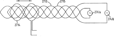
- I. position coder comprises:First parts and second parts, they can relatively move along measuring route, transmitter of second member supporting, described transmitter with by the receiver electromagnetic coupled of first member supporting, described transmitter and receiver are arranged to: in response to a signal that is sent by described transmitter, induce an output signal in described receiver, this output signal changes with described first parts and second parts relative position along described measuring route;At least one of wherein said receiver and transmitter comprises a circuit with a plurality of loop parts, described a plurality of loop partly passes described measuring route and is joined together to form first group of loop and second group of loop of arranging along described path, each loop extends along described path, and described loop is connected in series and is arranged as feasible: added together by the electromotive force (EMF) of identical alternating magnetic field induction and phase place electromotive force that responded in second group by the electromotive force (EMF) of identical alternating magnetic field induction in first group of loop is opposite in each loop in same group;It is characterized in that the loop that passes described measuring route in each group loop partly is arranged as the density that has variation along described measuring route, makes the magnetic field sensitivity of described circuit distribute by sinusoidal variations.
- 2. position coder as claimed in claim 1 is characterized in that total being square of described loop.
- 3. position coder as claimed in claim 1 or 2, it is characterized in that, at least one of described transmitter and receiver is made of a plurality of described circuit that are separated from each other, are laminated to each other on electric, and a plurality of loops of each circuit all spatially are separated from each other along described path.
- 4. position coder as claimed in claim 3, it is characterized in that, described transmitter and receiver described at least one constitute by two described first circuit, and each loop of each first circuit spatially the size (Ts/2) by 1/2nd each described loops is separated from each other along described path.
- 5. position coder as claimed in claim 1 or 2 is characterized in that, described circuit constitutes by arranging one by one along described path more than two groups described loop.
- 6. position coder as claimed in claim 1 or 2, it is characterized in that, described second parts also comprise along described path apart from second transmitter of the described first parts fixed range, and wherein the space interval between two transmitters makes the output signal of being responded in described receiver by described first transmitter become phase quadrature relationship with the output signal of being responded to by described second transmitter in described receiver.
- 7. position coder as claimed in claim 1 or 2 is characterized in that, described transmitter comprises an electromagnetic device, and wherein said second parts comprise the exciting circuit that is used for to this electromagnetic device energy supply.
- 8. according to the position coder of claim 7, be characterised in that described electromagnetic device is the resonant circuit with a coil and an electric capacity.
- 9. position coder according to Claim 8, be characterised in that described resonant circuit comprise a coil, electric capacity and with the quartz or the ceramic mould resonator of described coil and capacitances in series.
- 10. position coder according to Claim 8, be characterised in that, comprise a plurality of resonant circuits, resonance frequency difference separately, and dispose to such an extent that make it induce the alternating signal of respective resonant frequency when work in described receiver, the amplitude of alternating signal changes with respect to described first position component with it.
- 11. position coder as claimed in claim 7, it is characterized in that, it also has a drive unit and treating apparatus, drive unit is added on the described exciting circuit in order to the drive signal with described input, treating apparatus is in order to handling the signal induce in described receiver, and indicates the relative position of described first parts and second parts thus.
- 12. position coder as claimed in claim 11, can apply the pulse of described drive signal when it is characterized in that the work of described drive unit in the interim very first time, and can be during second time interval of the described very first time after at interval during the work of described treating apparatus the described signal that induces of processing.
- 13. position coder as claimed in claim 11 is characterized in that, described treating apparatus has a demoder, the phase matching of the signal that induces in described another circuit with described resonant circuit.
- 14. position coder as claimed in claim 11, it is characterized in that, described transmitter and described receiver described at least one two or more described circuit are arranged, the loop of each circuit spatially along described path separately and can calculate the trigonometric ratio of the signal that induces in the described receiver during work of described treating apparatus.
- 15. position coder as claimed in claim 1 or 2, it is characterized in that, the described output signal that induces in the described receiver as described first parts and second parts along the function of the relative position in described path by sinusoidal variation, and the one-period of described sinusoidal variations (Ts) is corresponding to the degree size of the relative motion of described first and second groups of loops.
- 16., be characterised in that described receiver is the described circuit that contains a plurality of described loop parts according to the position coder of claim 1 or 2.
- 17., be characterised in that described loop partly is supported on the plane surface of described second parts according to the position coder of claim 16.
- 18. according to the position coder of claim 17, be characterised in that described transmitter comprises a coil, the axle of described coil is perpendicular to the described plane surface of described second parts.
- 19. position coder as claimed in claim 17, it is characterized in that, described transmitter comprises a resonant circuit, and it comprises the coil of an electric capacity and two configurations of each interval one segment distance in described measuring route that are connected in series, and this distance can be regulated to reduce gap tilt effect.
- 20., be characterised in that described transmitter is the circuit with described a plurality of loop parts according to the position coder of claim 1.
- 21., be characterised in that described loop partly is supported on the plane surface of described first parts according to the position coder of claim 20.
- 22. according to the position coder of claim 21, be characterised in that described receiver comprises a conductor loop, the axle of described loop is perpendicular to the described plane surface of described first parts.
- 23. position coder as claimed in claim 1 or 2 is characterized in that, described first parts maintain static, and described second parts then can be with respect to described first component movement.
- 24. position coder as claimed in claim 1 or 2 is characterized in that, described measuring route is the bar straight line.
- 25. position coder according to claim 1 or 2, be characterised in that described transmitter and described receiver described at least one comprise at least two described circuit with loop group, they arrange that along described vertical path order described thus position coder can be judged the relative position of described first and second parts on two-dimensional directional.
- 26. position coder according to claim 1, be characterised in that described transmitter is the electromagnetism harmonic oscillator, described first parts comprise the exciting circuit to described harmonic oscillator energy supply, described harmonic oscillator is arranged as at work can induce the alternation output signal in response to the alternation drive signal that is applied to exciting circuit in described receiver, the frequency of the signal of described induction is different with the frequency of described drive signal.
- 27. position coder according to claim 1, be characterised in that described transmitter is the electronic impulse transponder, described first parts comprise the exciting circuit to the energy supply of described electronic impulse transponder, described electronic impulse transponder is arranged as at work can be by the magnetic field energy supply of the input drive signal generation that is applied to described exciting circuit, induce described output signal in described receiver, described output signal is different with described drive signal.
- 28., be characterised in that described first and second groups of loops arrange along described path order according to the position coder of claim 1.
- 29. a detection comprises the following steps: along the method for the relative position of first parts of measuring route relative motion and second partsA transmitter is set on second parts, it and the receiver electromagnetic coupled that is arranged on first parts, wherein said transmitter and receiver are arranged such that the signal that sends in response to by described transmitter, induce an output signal in described receiver, the amplitude of this output signal changes with the relative position of first and second parts along described measuring route;One of wherein described at least transmitter and receiver comprise a circuit with a plurality of loop parts, described a plurality of loop passes described measuring route, arrange according to the density that has variation along described measuring route, and be joined together to form along first group of loop and second group of loop of described path order arrangement, each loop extends along described path, and described loop is connected in series and is arranged as feasible: added together and electromotive force that responded in second group by the electromotive force (EMF) of identical alternating magnetic field induction in first group of loop is opposite by the electromotive force (EMF) of identical alternating magnetic field induction in each loop in same group;Send a signal from described transmitter; WithThe signal that detection is responded in receiver and from the derive relative position of described first and second parts of described signal.
- 30. method as claimed in claim 29 is characterized in that, described drive signal is made up of at 10 kilo hertzs of alternating signals to 1 megahertz range a frequency.
- 31. as claim 29 or 30 described methods, it is characterized in that, the described train of impulses that applies the described drive signal of step application of described drive signal, and described detection step detects the signal that induces in the described receiver after the described train of impulses of application drives signal.
Applications Claiming Priority (8)
| Application Number | Priority Date | Filing Date | Title |
|---|---|---|---|
| GB9409711A GB9409711D0 (en) | 1994-05-14 | 1994-05-14 | Spiral position sensor |
| GB9409711.0 | 1994-05-14 | ||
| GB9417353.1 | 1994-08-26 | ||
| GB9417353A GB9417353D0 (en) | 1994-05-14 | 1994-08-26 | An electronic rotation rate sensor for a combined float and turbine liquid flow rate transducer |
| GB9420597A GB9420597D0 (en) | 1994-05-05 | 1994-10-03 | An AC magnetic position measurement system for printers |
| GB9420597.8 | 1994-10-03 | ||
| GB9423861A GB9423861D0 (en) | 1994-11-25 | 1994-11-25 | Harmonic encoder |
| GB9423861.5 | 1994-11-25 |
Publications (2)
| Publication Number | Publication Date |
|---|---|
| CN1152954A CN1152954A (en) | 1997-06-25 |
| CN1085332C true CN1085332C (en) | 2002-05-22 |
Family
ID=27451155
Family Applications (1)
| Application Number | Title | Priority Date | Filing Date |
|---|---|---|---|
| CN95193948A Expired - Lifetime CN1085332C (en) | 1994-05-14 | 1995-05-15 | Position encoder |
Country Status (15)
| Country | Link |
|---|---|
| US (1) | US5815091A (en) |
| EP (1) | EP0760087B9 (en) |
| JP (1) | JP3804971B2 (en) |
| CN (1) | CN1085332C (en) |
| AT (1) | ATE165659T1 (en) |
| AU (1) | AU679378B2 (en) |
| BR (1) | BR9507650A (en) |
| CA (1) | CA2189959C (en) |
| DE (1) | DE69502283T3 (en) |
| DK (1) | DK0760087T4 (en) |
| ES (1) | ES2115382T5 (en) |
| HK (1) | HK1010796A1 (en) |
| MX (1) | MX9605535A (en) |
| SI (1) | SI0760087T1 (en) |
| WO (1) | WO1995031696A1 (en) |
Cited By (6)
| Publication number | Priority date | Publication date | Assignee | Title |
|---|---|---|---|---|
| CN1323285C (en) * | 2003-12-09 | 2007-06-27 | 发那科株式会社 | Encoder |
| CN100419383C (en) * | 2003-04-22 | 2008-09-17 | 量子精密仪器亚洲私人有限公司 | Quantum tunnelling transducer device |
| CN100445694C (en) * | 2004-04-09 | 2008-12-24 | Ksr科技公司 | Inductive position sensor |
| CN101427107B (en) * | 2006-04-26 | 2011-08-31 | 诺沃-诺迪斯克有限公司 | Contact free absolute position determination of a moving element in a medication delivery device |
| CN105849450A (en) * | 2013-11-05 | 2016-08-10 | 基伊埃图亨哈根有限公司 | Valve control device and processing valve |
| CN107087424A (en) * | 2014-10-28 | 2017-08-22 | 霍斯特塞德尔两合公司 | Position sensor, position-measurement device and the driving method for it |
Families Citing this family (174)
| Publication number | Priority date | Publication date | Assignee | Title |
|---|---|---|---|---|
| US20030062889A1 (en) * | 1996-12-12 | 2003-04-03 | Synaptics (Uk) Limited | Position detector |
| US6249234B1 (en) | 1994-05-14 | 2001-06-19 | Absolute Sensors Limited | Position detector |
| EP0743508A2 (en) * | 1995-05-16 | 1996-11-20 | Mitutoyo Corporation | Induced current position transducer |
| GB9523991D0 (en) * | 1995-11-23 | 1996-01-24 | Scient Generics Ltd | Position encoder |
| DE19612830C1 (en) | 1996-03-30 | 1997-07-24 | Hella Kg Hueck & Co | Drive pedal transmission with potentiometer as sensor |
| US5973494A (en) * | 1996-05-13 | 1999-10-26 | Mitutoyo Corporation | Electronic caliper using a self-contained, low power inductive position transducer |
| US6788221B1 (en) | 1996-06-28 | 2004-09-07 | Synaptics (Uk) Limited | Signal processing apparatus and method |
| GB9613673D0 (en) * | 1996-06-28 | 1996-08-28 | Scient Generics Ltd | Rotary spiral improvements |
| US5886519A (en) * | 1997-01-29 | 1999-03-23 | Mitutoyo Corporation | Multi-scale induced current absolute position transducer |
| US5841274A (en) * | 1997-01-29 | 1998-11-24 | Mitutoyo Corporation | Induced current absolute position transducer using a code-track-type scale and read head |
| US6005387A (en) * | 1997-04-16 | 1999-12-21 | Mitutoyo Corporation | Reduced offset high accuracy induced current position transducer |
| EP0985132B1 (en) | 1997-05-28 | 2005-11-09 | Synaptics (UK) Limited | Method of and wire bonding apparatus for manufacturing a transducer |
| EP0990122B1 (en) * | 1997-06-17 | 2004-03-31 | Synaptics (UK) Limited | Detecting relative position and orientation |
| DE19738839A1 (en) * | 1997-09-05 | 1999-03-11 | Hella Kg Hueck & Co | Inductive angle sensor |
| DE19738834A1 (en) | 1997-09-05 | 1999-03-11 | Hella Kg Hueck & Co | Inductive angle sensor for a motor vehicle |
| US5936399A (en) * | 1997-09-16 | 1999-08-10 | Mitutoyo Corporation | Inductive position transducer having a multi-tap receiver winding |
| GB9720954D0 (en) | 1997-10-02 | 1997-12-03 | Scient Generics Ltd | Commutators for motors |
| GB9721891D0 (en) * | 1997-10-15 | 1997-12-17 | Scient Generics Ltd | Symmetrically connected spiral transducer |
| US5901458A (en) * | 1997-11-21 | 1999-05-11 | Mitutoyo Corporation | Electronic caliper using a reduced offset induced current position transducer |
| US6049204A (en) * | 1997-11-21 | 2000-04-11 | Mitutoyo Corporation | Electronic linear scale using a reduced offset high accuracy induced current position transducer |
| DE19757689C2 (en) | 1997-12-23 | 2001-02-15 | Siedle Horst Gmbh & Co Kg | Inductive transmitter for paths |
| US6356255B1 (en) * | 1998-04-07 | 2002-03-12 | Interval Research Corporation | Methods and systems for providing programmable computerized interactors |
| DE19816936A1 (en) * | 1998-04-16 | 1999-10-21 | Siemens Ag | Antenna transponder arrangement for power transmission and angle measurement |
| GB9811151D0 (en) | 1998-05-22 | 1998-07-22 | Scient Generics Ltd | Rotary encoder |
| US6417663B1 (en) | 1998-09-01 | 2002-07-09 | Interval Research Corporation | Detecting physical objects states using electromagnetic sensors |
| MXPA01005267A (en) * | 1998-11-27 | 2002-04-24 | Synaptics Uk Ltd | Position sensor. |
| US6329813B1 (en) | 1998-12-17 | 2001-12-11 | Mitutoyo Corporation | Reduced offset high accuracy induced current absolute position transducer |
| US7019672B2 (en) * | 1998-12-24 | 2006-03-28 | Synaptics (Uk) Limited | Position sensor |
| ATE264496T1 (en) * | 1999-02-05 | 2004-04-15 | Siedle Horst Gmbh & Co Kg | PATH AND/OR ANGLE TRANSDUCER WITH MEANING-SHAPED MEASUREMENT WINDING |
| DE19905847C2 (en) * | 1999-02-05 | 2001-02-22 | Siedle Horst Gmbh & Co Kg | Displacement and / or angle sensors with a meandering measuring winding |
| DE19920190A1 (en) * | 1999-05-03 | 2000-11-09 | Hella Kg Hueck & Co | Inductive linear sensor and inductive angle sensor |
| US7047826B2 (en) * | 1999-05-07 | 2006-05-23 | Northwestern University | Force sensors |
| GB9913935D0 (en) | 1999-06-15 | 1999-08-18 | Scient Generics Ltd | Position encoder for cylindrical geometries |
| US6364735B1 (en) | 1999-08-13 | 2002-04-02 | Bill Goodman Consulting Llc | RF identification system for use in toys |
| US6361396B1 (en) | 1999-08-13 | 2002-03-26 | Bill Goodman Consulting, Llc | RF identification system for use in toys |
| ATE310981T1 (en) * | 1999-12-10 | 2005-12-15 | Sensopad Ltd | HUMAN-MACHINE INTERFACE WITH RELATIVE POSITION SENSOR |
| US6791452B2 (en) | 1999-12-29 | 2004-09-14 | Massachusetts Institute Of Technology | Platform for item sensing and identification |
| US7878905B2 (en) | 2000-02-22 | 2011-02-01 | Creative Kingdoms, Llc | Multi-layered interactive play experience |
| US6418788B2 (en) * | 2000-02-25 | 2002-07-16 | George A. Articolo | Digital electronic liquid density/liquid level meter |
| JP3504904B2 (en) * | 2000-03-13 | 2004-03-08 | 株式会社ミツトヨ | Inductive transducer and electronic caliper |
| US6404340B1 (en) | 2000-06-19 | 2002-06-11 | Massachusetts Institute Of Technology | Multiple-axis tracking of passive resonant structures |
| JP3521132B2 (en) * | 2000-07-24 | 2004-04-19 | 株式会社ミツトヨ | Relative displacement detection unit and relative displacement detection device |
| US6642711B2 (en) | 2001-01-24 | 2003-11-04 | Texas Instruments Incorporated | Digital inductive position sensor |
| US6838872B1 (en) * | 2001-04-18 | 2005-01-04 | Interval Research Corporation | Position detecting system and method |
| ATE398803T1 (en) | 2001-05-21 | 2008-07-15 | Synaptics Uk Ltd | POSITION SENSOR |
| GB0315738D0 (en) * | 2003-07-04 | 2003-08-13 | Sensopad Technologies Ltd | Position encoder |
| US7196604B2 (en) * | 2001-05-30 | 2007-03-27 | Tt Electronics Technology Limited | Sensing apparatus and method |
| GB0126014D0 (en) * | 2001-10-30 | 2001-12-19 | Sensopad Technologies Ltd | Modulated field position sensor |
| DE60228087D1 (en) * | 2001-06-22 | 2008-09-18 | Compumedics Ltd | ASYMMETRIC INDUCTIVE BAND |
| WO2003038380A1 (en) * | 2001-10-30 | 2003-05-08 | Scientific Generics Limited | A position sensor |
| US6614392B2 (en) * | 2001-12-07 | 2003-09-02 | Delaware Capital Formation, Inc. | Combination RFID and GPS functionality on intelligent label |
| JP4249628B2 (en) * | 2002-02-05 | 2009-04-02 | センソパッド リミテッド | Instruments and methods |
| US7881896B2 (en) | 2002-02-14 | 2011-02-01 | Faro Technologies, Inc. | Portable coordinate measurement machine with integrated line laser scanner |
| AU2003209143A1 (en) | 2002-02-14 | 2003-09-04 | Faro Technologies, Inc. | Portable coordinate measurement machine with articulated arm |
| USRE42082E1 (en) | 2002-02-14 | 2011-02-01 | Faro Technologies, Inc. | Method and apparatus for improving measurement accuracy of a portable coordinate measurement machine |
| US6957496B2 (en) | 2002-02-14 | 2005-10-25 | Faro Technologies, Inc. | Method for improving measurement accuracy of a portable coordinate measurement machine |
| US20070066396A1 (en) | 2002-04-05 | 2007-03-22 | Denise Chapman Weston | Retail methods for providing an interactive product to a consumer |
| AU2003232360A1 (en) | 2002-06-05 | 2003-12-22 | Synaptics (Uk) Limited | Signal transfer method and apparatus |
| EP1552249A2 (en) * | 2002-10-16 | 2005-07-13 | TT Electronics Technology Limited | Position sensing apparatus and method |
| GB2394293A (en) * | 2002-10-16 | 2004-04-21 | Gentech Invest Group Ag | Inductive sensing apparatus and method |
| US7023199B2 (en) * | 2002-12-31 | 2006-04-04 | Caterpillar Inc. | Position sensing cylinder cap for ease of service and assembly |
| GB0300291D0 (en) * | 2003-01-07 | 2003-02-05 | Sensopad Technologies Ltd | Position encoder |
| AU2003295167A1 (en) * | 2003-01-07 | 2004-07-29 | Sensopad Limited | Sensing apparatus and method |
| GB0303627D0 (en) * | 2003-02-17 | 2003-03-19 | Sensopad Technologies Ltd | Sensing method and apparatus |
| JP2006525529A (en) * | 2003-05-06 | 2006-11-09 | エスアールアイ インターナショナル | System and method for recording piston rod position information in a magnetic layer on a piston rod |
| US6943550B2 (en) * | 2003-05-09 | 2005-09-13 | The University Of Hong Kong | High temperature superconductor tape RF coil for magnetic resonance imaging |
| US6999007B2 (en) * | 2003-05-15 | 2006-02-14 | Delphi Technologies, Inc. | Linear position sensor |
| GB0319945D0 (en) | 2003-08-26 | 2003-09-24 | Synaptics Uk Ltd | Inductive sensing system |
| US6952086B1 (en) | 2003-10-10 | 2005-10-04 | Curtiss-Wright Electro-Mechanical Corporation | Linear position sensing system and coil switching methods for closed-loop control of large linear induction motor systems |
| JP2005156348A (en) * | 2003-11-26 | 2005-06-16 | Okuma Corp | Device for detecting position |
| ATE398765T1 (en) | 2004-03-01 | 2008-07-15 | Sagentia Ltd | POSITION SENSOR |
| US6895751B1 (en) | 2004-03-08 | 2005-05-24 | Christopher Greentree | Vane control |
| JP2005249730A (en) * | 2004-03-08 | 2005-09-15 | Niles Co Ltd | Electromagnetic induction type displacement sensor |
| US7121185B2 (en) * | 2004-05-28 | 2006-10-17 | Caterpillar Inc. | Hydraulic cylinder having a snubbing valve |
| GB2417088B (en) * | 2004-08-09 | 2006-11-15 | Sensopad Ltd | Sensing apparatus and method |
| GB0423617D0 (en) * | 2004-10-23 | 2004-11-24 | Murray Joseph W | Dial indicator system |
| US20070126416A1 (en) * | 2004-10-26 | 2007-06-07 | Sentrinsic Llc | Displacement Sensor Systems and Methods |
| WO2007011402A2 (en) * | 2004-10-26 | 2007-01-25 | Georgia Tech Research Corporation | Displacement sensor |
| GB0427410D0 (en) * | 2004-12-14 | 2005-01-19 | Kreit Darran | Data acquisition system |
| GB0427761D0 (en) | 2004-12-20 | 2005-01-19 | Kreit Darran | Position encoder for a rotor |
| EP1828722B1 (en) * | 2004-12-20 | 2011-11-02 | Howard, Mark Anthony | Inductive position sensor |
| US7530657B2 (en) * | 2005-02-03 | 2009-05-12 | Hewlett-Packard Development Company, L.P. | Media transport encoder accuracy |
| DE102005006581A1 (en) * | 2005-02-11 | 2006-08-24 | Volkswagen Ag | Object position e.g. angle, measurement sensor for use in motor vehicle, has signal generator to output sinusoidal position signal, which includes information about position of object, where information is coded in frequency of signal |
| US7023363B1 (en) * | 2005-02-17 | 2006-04-04 | Saiful Bahari Saidan | Position encoding using impedance comparison |
| US7111912B1 (en) | 2005-03-23 | 2006-09-26 | Honeywell International Inc. | Control handle with spiral position sensor and integral switches |
| US7259553B2 (en) | 2005-04-13 | 2007-08-21 | Sri International | System and method of magnetically sensing position of a moving component |
| GB2426591B (en) | 2005-05-27 | 2009-12-30 | Tt Electronics Technology Ltd | Sensing apparatus and method |
| WO2007031891A1 (en) * | 2005-09-12 | 2007-03-22 | Koninklijke Philips Electronics N.V. | Method to determine a relative position of devices in a network, and network of devices for carrying out the method |
| GB0606055D0 (en) | 2006-03-25 | 2006-05-03 | Scient Generics Ltd | Non-contact wheel encoder |
| DE102006026543B4 (en) * | 2006-06-07 | 2010-02-04 | Vogt Electronic Components Gmbh | Position encoder and associated method for detecting a position of a rotor of a machine |
| US7562591B2 (en) * | 2006-06-26 | 2009-07-21 | KRS Technologies Co. | Steering angle sensor |
| US9201556B2 (en) | 2006-11-08 | 2015-12-01 | 3M Innovative Properties Company | Touch location sensing system and method employing sensor data fitting to a predefined curve |
| US8207944B2 (en) | 2006-12-19 | 2012-06-26 | 3M Innovative Properties Company | Capacitance measuring circuit and method |
| US8243049B2 (en) * | 2006-12-20 | 2012-08-14 | 3M Innovative Properties Company | Untethered stylus employing low current power converter |
| US20080149401A1 (en) * | 2006-12-20 | 2008-06-26 | 3M Innovative Properties Company | Untethered stylus employing separate communication channels |
| US8134542B2 (en) * | 2006-12-20 | 2012-03-13 | 3M Innovative Properties Company | Untethered stylus employing separate communication and power channels |
| US7956851B2 (en) | 2006-12-20 | 2011-06-07 | 3M Innovative Properties Company | Self-tuning drive source employing input impedance phase detection |
| US8040329B2 (en) | 2006-12-20 | 2011-10-18 | 3M Innovative Properties Company | Frequency control circuit for tuning a resonant circuit of an untethered device |
| US7787259B2 (en) | 2006-12-28 | 2010-08-31 | 3M Innovative Properties Company | Magnetic shield for use in a location sensing system |
| US8040330B2 (en) | 2006-12-28 | 2011-10-18 | 3M Innovative Properties Company | Untethered stylus empolying multiple reference frequency communication |
| US8089474B2 (en) * | 2006-12-28 | 2012-01-03 | 3M Innovative Properties Company | Location sensing system and method employing adaptive drive signal adjustment |
| DE102007015524A1 (en) * | 2007-03-30 | 2008-10-09 | Cherry Gmbh | Method for producing an inductive damping element and inductive eddy current actuating element |
| EP2145158B1 (en) * | 2007-05-10 | 2018-03-07 | Cambridge Integrated Circuits Limited | Transducer |
| US20090058430A1 (en) * | 2007-09-05 | 2009-03-05 | Sentrinsic | Systems and Methods for Sensing Positions of Components |
| JP5224838B2 (en) * | 2008-02-04 | 2013-07-03 | 株式会社ミツトヨ | Electromagnetic induction encoder |
| WO2009115764A1 (en) | 2008-03-19 | 2009-09-24 | Sagentia Sensors Limited | Processing circuitry |
| US8082785B2 (en) * | 2008-07-31 | 2011-12-27 | Illinois Tool Works Inc. | Inductive liquid-level sensor |
| JP5189510B2 (en) * | 2009-01-22 | 2013-04-24 | 愛三工業株式会社 | Position sensor |
| JP5239025B2 (en) * | 2009-03-11 | 2013-07-17 | 株式会社ミツトヨ | Inductive detection type rotary encoder |
| CN201429426Y (en) * | 2009-04-24 | 2010-03-24 | 广东升威电子制品有限公司 | Plastic-sealed strip sliding encoder |
| US8237453B2 (en) | 2009-07-24 | 2012-08-07 | Synaptics Incorporated | Capacitive sensing pattern |
| US8570297B2 (en) | 2009-12-14 | 2013-10-29 | Synaptics Incorporated | System and method for measuring individual force in multi-object sensing |
| WO2011100412A2 (en) * | 2010-02-11 | 2011-08-18 | Sri International | Displacement measurement system and method using magnetic encodings |
| DE102010016333B4 (en) | 2010-04-06 | 2018-02-08 | Turck Holding Gmbh | Knee lever tensioning device with an angle detection device by a resonant circuit |
| US8607640B2 (en) | 2010-07-19 | 2013-12-17 | Odd Harald Steen Eriksen | Sensor for measuring large mechanical strains in shear or lateral translation |
| US8359932B2 (en) | 2010-07-19 | 2013-01-29 | Goodrich Corporation | Systems and methods for mounting landing gear strain sensors |
| US8659307B2 (en) | 2010-08-17 | 2014-02-25 | Rosemount Aerospace Inc. | Capacitive sensors for monitoring load bearing on pins |
| US8286508B2 (en) * | 2010-07-19 | 2012-10-16 | Goodrich Corporation | Systems and methods for measuring angular motion |
| US8933713B2 (en) | 2010-07-19 | 2015-01-13 | Goodrich Corporation | Capacitive sensors for monitoring loads |
| US8627727B2 (en) | 2010-07-19 | 2014-01-14 | United Technologies Corporation | Sensor for measuring large mechanical strains with fine adjustment device |
| US10131419B2 (en) | 2010-10-15 | 2018-11-20 | Goodrich Corporation | Systems and methods for detecting landing gear ground loads |
| GB2488389C (en) | 2010-12-24 | 2018-08-22 | Cambridge Integrated Circuits Ltd | Position sensing transducer |
| US8572838B2 (en) | 2011-03-02 | 2013-11-05 | Honeywell International Inc. | Methods for fabricating high temperature electromagnetic coil assemblies |
| US8466767B2 (en) | 2011-07-20 | 2013-06-18 | Honeywell International Inc. | Electromagnetic coil assemblies having tapered crimp joints and methods for the production thereof |
| JP5809479B2 (en) * | 2011-08-03 | 2015-11-11 | 株式会社ミツトヨ | Electromagnetic induction type absolute position measurement encoder |
| DE202011051104U1 (en) | 2011-08-25 | 2012-11-28 | Turck Holding Gmbh | Rotation angle or displacement sensor |
| GB201117201D0 (en) * | 2011-10-04 | 2011-11-16 | Howard Mark A | Detector |
| US8860541B2 (en) | 2011-10-18 | 2014-10-14 | Honeywell International Inc. | Electromagnetic coil assemblies having braided lead wires and methods for the manufacture thereof |
| US9567097B2 (en) | 2012-02-03 | 2017-02-14 | Rosemount Aerospace Inc. | System and method for real-time aircraft performance monitoring |
| US8754735B2 (en) | 2012-04-30 | 2014-06-17 | Honeywell International Inc. | High temperature electromagnetic coil assemblies including braided lead wires and methods for the fabrication thereof |
| US9076581B2 (en) | 2012-04-30 | 2015-07-07 | Honeywell International Inc. | Method for manufacturing high temperature electromagnetic coil assemblies including brazed braided lead wires |
| US9471169B2 (en) * | 2012-05-22 | 2016-10-18 | Synaptics Incorporated | Force enhanced input device |
| GB2503006B (en) | 2012-06-13 | 2017-08-09 | Cambridge Integrated Circuits Ltd | Position sensing transducer |
| JP2014002120A (en) * | 2012-06-20 | 2014-01-09 | Tokai Rika Co Ltd | Non-contact sensor and shift lever device |
| JP6012038B2 (en) * | 2012-09-27 | 2016-10-25 | 株式会社ワコム | Electromagnetic induction type position detection sensor and position detection apparatus |
| US9027228B2 (en) | 2012-11-29 | 2015-05-12 | Honeywell International Inc. | Method for manufacturing electromagnetic coil assemblies |
| DE102013100841B4 (en) | 2013-01-29 | 2016-12-15 | Turck Holding Gmbh | Position transducer with a sensor element and a plunger coil |
| FR3002034B1 (en) * | 2013-02-12 | 2015-03-20 | Continental Automotive France | INDUCTIVE POSITION SENSOR |
| DE102013203494A1 (en) | 2013-03-01 | 2014-09-04 | Peter Kunow | position sensor |
| US9722464B2 (en) | 2013-03-13 | 2017-08-01 | Honeywell International Inc. | Gas turbine engine actuation systems including high temperature actuators and methods for the manufacture thereof |
| TWI497899B (en) | 2013-08-05 | 2015-08-21 | Ind Tech Res Inst | Mechanical encoder |
| KR102131776B1 (en) * | 2013-08-06 | 2020-07-08 | 삼성전자주식회사 | Input device and electronic device including the same |
| GB2517152A (en) * | 2013-08-12 | 2015-02-18 | Gde Technology Ltd | Position sensor |
| US9360294B2 (en) * | 2013-10-31 | 2016-06-07 | Ascension Technology Corporation | Magnetic sensors |
| DE102013225873A1 (en) * | 2013-12-13 | 2015-06-18 | Continental Teves Ag & Co. Ohg | Inductive sensor based on the vernier principle |
| DE102013225874A1 (en) * | 2013-12-13 | 2015-06-18 | Continental Teves Ag & Co. Ohg | Inductive rotation angle sensor |
| DE102014117200A1 (en) | 2014-11-24 | 2016-05-25 | Beckhoff Automation Gmbh | Position detection system |
| JP6480809B2 (en) | 2015-05-21 | 2019-03-13 | オークマ株式会社 | Multi revolution detector |
| CN107922162B (en) * | 2015-08-14 | 2020-09-08 | 奥的斯电梯公司 | Elevator car position detection assembly |
| EP3384272A4 (en) * | 2015-11-30 | 2020-04-01 | Bourns, Inc. | Detecting fluid characteristics via a float |
| JP6021136B1 (en) * | 2016-02-03 | 2016-11-09 | 三菱重工工作機械株式会社 | Electromagnetic induction type position detector |
| US11448524B2 (en) | 2016-04-07 | 2022-09-20 | Phoenix America Inc. | Multipole magnet for use with a pitched magnetic sensor |
| DE102016115483A1 (en) * | 2016-08-21 | 2018-02-22 | Krohne Messtechnik Gmbh | Method for operating a magnetic-inductive flowmeter and electromagnetic flowmeter |
| KR102514336B1 (en) | 2016-12-01 | 2023-03-24 | 워렌 인더스트리즈 엘티디. | IMPROVED DOOR CONTROL SYSTEM |
| DE102016224856A1 (en) * | 2016-12-13 | 2018-06-14 | Robert Bosch Gmbh | Sensor system for determining at least one rotational property of an element rotating about at least one axis of rotation |
| US10422666B2 (en) * | 2016-12-23 | 2019-09-24 | Mitutoyo Corporation | Electronic position encoder and method for reducing short range errors |
| US11535488B2 (en) * | 2017-08-28 | 2022-12-27 | Otis Elevator Company | Elevator position detection systems |
| DE102017222063A1 (en) * | 2017-12-06 | 2019-06-06 | Dr. Johannes Heidenhain Gmbh | Inductive position measuring device |
| US10451447B2 (en) * | 2018-01-04 | 2019-10-22 | Mitsubishi Electric Research Laboratories, Inc. | Polarization-dependent position encoder |
| EP3517896B1 (en) * | 2018-01-30 | 2020-12-30 | Mecos AG | Contactless radial position sensor having improved response behavior to target defects |
| US10551217B2 (en) * | 2018-06-29 | 2020-02-04 | Mitutoyo Corporation | Receiver line spacing in inductive position encoder |
| DE112018008038T5 (en) | 2018-10-16 | 2021-06-24 | Ab Elektronik Gmbh | Position sensing device and method |
| US11555940B2 (en) | 2018-10-31 | 2023-01-17 | KYOCERA AVX Components (Werne), GmbH | Position sensing apparatus and method |
| DE102018220032A1 (en) * | 2018-11-22 | 2020-05-28 | Conti Temic Microelectronic Gmbh | Magnetic position sensor system |
| CN109484933B (en) * | 2018-12-29 | 2020-07-17 | 日立电梯(中国)有限公司 | Elevator car position and speed detection system and self-detection method thereof |
| US11293744B2 (en) * | 2019-03-01 | 2022-04-05 | Renesas Electronics America Inc. | Method for increasing the position measurement accuracy using inductive position sensor |
| FR3094085B1 (en) * | 2019-03-22 | 2021-02-26 | Continental Automotive | Reduced width inductive position sensor |
| US11460326B2 (en) * | 2019-08-19 | 2022-10-04 | KYOCERA AVX Components (Werne), GmbH | Inductive position sensing apparatus and method for the same |
| EP3792600A1 (en) * | 2019-09-12 | 2021-03-17 | TE Connectivity Belgium BVBA | Sensor device for measuring the rotational position of an element |
| JP7347100B2 (en) * | 2019-10-11 | 2023-09-20 | Tdk株式会社 | rotating electric machine |
| JP2021096160A (en) * | 2019-12-17 | 2021-06-24 | 株式会社ミツトヨ | Scale and encoder |
| DE102021103515A1 (en) * | 2021-02-15 | 2022-08-18 | Balluff Gmbh | Inductive displacement sensor with movable measuring head |
| CN115435668A (en) * | 2022-09-13 | 2022-12-06 | Oppo广东移动通信有限公司 | Measuring device and electronic apparatus |
| CN115435669A (en) * | 2022-09-13 | 2022-12-06 | Oppo广东移动通信有限公司 | Measuring device and electronic apparatus |
Family Cites Families (44)
| Publication number | Priority date | Publication date | Assignee | Title |
|---|---|---|---|---|
| US2145742A (en) * | 1935-09-18 | 1939-01-31 | Gen Electric | Band filtering device with variable band breadth |
| US2942212A (en) * | 1956-01-31 | 1960-06-21 | British Thomson Houston Co Ltd | Position sensing devices |
| DE1134848B (en) * | 1956-10-25 | 1962-08-16 | S E A Soc D Elctronique Et D A | Difference generator for generating an output voltage which indicates the difference between a function of two mechanical input signals |
| US3219956A (en) * | 1961-09-22 | 1965-11-23 | Sperry Rand Corp Ford Instr Co | Brushless rotary inductive devices |
| US3297940A (en) * | 1962-06-01 | 1967-01-10 | Internat Instr Inc | Means for reproducing a pattern as a d. c. output |
| GB1122763A (en) * | 1967-03-14 | 1968-08-07 | Merckle Flugzeugwerke Gmbh | Inductive angular position transmitter |
| US3647963A (en) * | 1969-03-10 | 1972-03-07 | Bendix Corp | Automatic coordinate determining device |
| CH548016A (en) † | 1971-11-12 | 1974-04-11 | Inductosyn Corp | POSITION MEASURING TRANSFORMER. |
| US3851242A (en) * | 1972-06-27 | 1974-11-26 | J Ellis | Frequency-modulated eddy-current proximity gage |
| FR2207594A5 (en) * | 1972-11-20 | 1974-06-14 | Cem Comp Electro Mec | |
| US3906436A (en) * | 1973-02-08 | 1975-09-16 | Sumitomo Electric Industries | Detection system for the location of moving objects |
| NL7305172A (en) * | 1973-04-13 | 1974-10-15 | ||
| GB1485646A (en) * | 1973-11-16 | 1977-09-14 | Hitachi Ltd | Digital displacement sensors |
| US3898635A (en) * | 1973-12-20 | 1975-08-05 | Ibm | Position measuring transformer |
| DE2711597A1 (en) * | 1976-03-23 | 1977-10-06 | Hughes Microelectronics Ltd | CONVERTER FOR GENERATING ELECTRICAL SIGNALS THAT ARE A FUNCTION OF SEVERAL DIFFERENT PARAMETERS |
| IT1111425B (en) * | 1977-05-18 | 1986-01-13 | Conte Alberto | ABSOLUTE PRECISION TRANSDUCER FOR MEASUREMENT OF LINEAR OR ANGULAR POSITIONS |
| US4156192A (en) * | 1977-08-11 | 1979-05-22 | Moskovskoe Nauchno-Proizvodstvennoe Obiedinenie Po Stroitelstvu I Dorozhnomu Mashinostroeniju | Inductive displacement transducer using plural magnetic screens rotatable about different axis to modify an inductance proportional to the displacement |
| GB2012431A (en) * | 1977-08-17 | 1979-07-25 | Hayter J E | Electromagnetic Position Transducer Uses Eddy Currents Induced in Conductive Member |
| GB1604824A (en) * | 1978-05-11 | 1981-12-16 | Ranco Inc | Displacement measuring transducers |
| US4282485A (en) * | 1978-05-22 | 1981-08-04 | Pneumo Corporation | Linear variable phase transformer with constant magnitude output |
| GB2059593B (en) * | 1979-08-20 | 1984-02-08 | Cain Encoder | Apparatus and method for remotely determining the position speed and/or direction of movement of a movable object |
| GB2064125A (en) * | 1979-11-27 | 1981-06-10 | Atomic Energy Authority Uk | Position indicating apparatus |
| GB2074736B (en) * | 1980-04-26 | 1984-03-07 | Lucas Industries Ltd | Displacement measuring transducers and their use for sensing vehicle suspension displacements |
| GB2103943B (en) * | 1981-07-21 | 1985-09-04 | Scisys W Limited | Electronic game board |
| US4507638A (en) * | 1981-12-10 | 1985-03-26 | Amnon Brosh | Rotary position sensors employing planar coils |
| US4697144A (en) * | 1984-04-19 | 1987-09-29 | Verify Electronics Limited | Position sensing apparatus |
| IE55855B1 (en) * | 1984-10-19 | 1991-01-30 | Kollmorgen Ireland Ltd | Position and speed sensors |
| US4723446A (en) * | 1985-04-04 | 1988-02-09 | Kanto Seiki Co., Ltd. | Device for measuring displacement |
| AT383212B (en) * | 1985-07-10 | 1987-06-10 | Rsf Elektronik Gmbh | LENGTH MEASURING SYSTEM FOR MACHINE TOOLS |
| US4985691A (en) * | 1986-02-26 | 1991-01-15 | University Of Pittsburgh | Contactless motion sensor |
| JPS6370326A (en) † | 1986-09-12 | 1988-03-30 | Wacom Co Ltd | Position detector |
| US4893077A (en) * | 1987-05-28 | 1990-01-09 | Auchterlonie Richard C | Absolute position sensor having multi-layer windings of different pitches providing respective indications of phase proportional to displacement |
| JP2583509B2 (en) * | 1987-06-16 | 1997-02-19 | 株式会社 ワコム | Coordinate input device |
| JPS6434158A (en) † | 1987-07-28 | 1989-02-03 | Tamagawa Seiki Co Ltd | Brushless resolver device |
| NL8900750A (en) * | 1989-03-28 | 1990-10-16 | Philips Nv | DEVICE FOR MEASURING A RELATIVE MOVEMENT. |
| MY106855A (en) † | 1989-08-24 | 1995-08-30 | Sony Corp | Input devices. |
| DE68901599D1 (en) * | 1989-10-25 | 1992-06-25 | Saitek Ltd | ELECTRONIC PLAYER. |
| US5239288A (en) † | 1990-03-09 | 1993-08-24 | Transicoil Inc. | Resolver having planar windings |
| JPH06507476A (en) * | 1991-01-04 | 1994-08-25 | サイエンティフィック ジェネリックス リミテッド | Display device and its device |
| JPH05187803A (en) * | 1992-01-14 | 1993-07-27 | Kanbayashi Seisakusho:Kk | Sensor |
| GB2273778A (en) * | 1992-12-22 | 1994-06-29 | Tds Cad Graphics Limited | Cordless digitizer |
| GB9309073D0 (en) * | 1993-05-01 | 1993-06-16 | Dames Andrew N | Resonator orientation sensing |
| US5434372A (en) * | 1993-08-19 | 1995-07-18 | Acer Peripherals, Inc. | Position detecting apparatus with coils of opposite loop direction |
| EP0775001A4 (en) * | 1994-07-28 | 1999-09-01 | Super Dimension Inc | Computerized game board |
-
1995
- 1995-05-15 MX MX9605535A patent/MX9605535A/en active IP Right Grant
- 1995-05-15 DK DK95918680T patent/DK0760087T4/en active
- 1995-05-15 WO PCT/GB1995/001095 patent/WO1995031696A1/en active IP Right Grant
- 1995-05-15 BR BR9507650A patent/BR9507650A/en not_active IP Right Cessation
- 1995-05-15 JP JP52945695A patent/JP3804971B2/en not_active Expired - Lifetime
- 1995-05-15 CA CA002189959A patent/CA2189959C/en not_active Expired - Lifetime
- 1995-05-15 AU AU24513/95A patent/AU679378B2/en not_active Expired
- 1995-05-15 AT AT95918680T patent/ATE165659T1/en active
- 1995-05-15 DE DE1995602283 patent/DE69502283T3/en not_active Expired - Lifetime
- 1995-05-15 EP EP95918680A patent/EP0760087B9/en not_active Expired - Lifetime
- 1995-05-15 US US08/737,505 patent/US5815091A/en not_active Expired - Lifetime
- 1995-05-15 SI SI9530098T patent/SI0760087T1/en not_active IP Right Cessation
- 1995-05-15 CN CN95193948A patent/CN1085332C/en not_active Expired - Lifetime
- 1995-05-15 ES ES95918680T patent/ES2115382T5/en not_active Expired - Lifetime
-
1998
- 1998-10-22 HK HK98111447A patent/HK1010796A1/en not_active IP Right Cessation
Cited By (9)
| Publication number | Priority date | Publication date | Assignee | Title |
|---|---|---|---|---|
| CN100419383C (en) * | 2003-04-22 | 2008-09-17 | 量子精密仪器亚洲私人有限公司 | Quantum tunnelling transducer device |
| CN1323285C (en) * | 2003-12-09 | 2007-06-27 | 发那科株式会社 | Encoder |
| CN100445694C (en) * | 2004-04-09 | 2008-12-24 | Ksr科技公司 | Inductive position sensor |
| CN101427107B (en) * | 2006-04-26 | 2011-08-31 | 诺沃-诺迪斯克有限公司 | Contact free absolute position determination of a moving element in a medication delivery device |
| CN105849450A (en) * | 2013-11-05 | 2016-08-10 | 基伊埃图亨哈根有限公司 | Valve control device and processing valve |
| CN105849450B (en) * | 2013-11-05 | 2018-09-04 | 基伊埃图亨哈根有限公司 | Control valve device and process valve |
| CN107087424A (en) * | 2014-10-28 | 2017-08-22 | 霍斯特塞德尔两合公司 | Position sensor, position-measurement device and the driving method for it |
| US10564009B2 (en) | 2014-10-28 | 2020-02-18 | Horst Siedle Gmbh & Co. Kg | Position sensor, position measuring device and method for the operation thereof |
| CN107087424B (en) * | 2014-10-28 | 2020-06-05 | 霍斯特塞德尔两合公司 | Position sensor, position measuring device, and driving method therefor |
Also Published As
| Publication number | Publication date |
|---|---|
| US5815091A (en) | 1998-09-29 |
| EP0760087B1 (en) | 1998-04-29 |
| DE69502283T2 (en) | 1998-11-05 |
| DE69502283T3 (en) | 2004-11-18 |
| EP0760087B9 (en) | 2005-01-05 |
| AU679378B2 (en) | 1997-06-26 |
| DE69502283D1 (en) | 1998-06-04 |
| DK0760087T4 (en) | 2004-08-09 |
| AU2451395A (en) | 1995-12-05 |
| CN1152954A (en) | 1997-06-25 |
| HK1010796A1 (en) | 1999-06-25 |
| ES2115382T5 (en) | 2004-12-01 |
| ATE165659T1 (en) | 1998-05-15 |
| JPH10500481A (en) | 1998-01-13 |
| CA2189959C (en) | 2005-11-15 |
| DK0760087T3 (en) | 1999-02-22 |
| EP0760087B2 (en) | 2004-04-21 |
| BR9507650A (en) | 1997-09-09 |
| WO1995031696A1 (en) | 1995-11-23 |
| MX9605535A (en) | 1998-02-28 |
| CA2189959A1 (en) | 1995-11-23 |
| EP0760087A1 (en) | 1997-03-05 |
| ES2115382T3 (en) | 1998-06-16 |
| SI0760087T1 (en) | 1998-10-31 |
| JP3804971B2 (en) | 2006-08-02 |
Similar Documents
| Publication | Publication Date | Title |
|---|---|---|
| CN1085332C (en) | Position encoder | |
| CN1278104C (en) | Induction sensing apparatus and method | |
| US6561022B1 (en) | Position encoder | |
| US6011389A (en) | Induced current position transducer having a low power electronic circuit | |
| CN101501454B (en) | A position encoder and a method for detecting the position of a movable part of a machine | |
| US6002250A (en) | Electronic linear scale using a self-contained, low-power inductive position transducer | |
| MXPA96005535A (en) | Posic codifier | |
| CN101153792B (en) | Rotary encoder and method for its operation | |
| US6611138B2 (en) | Inductive measuring device for detecting relative position and/or movement | |
| CN101545754B (en) | Positioning device and method for its operation | |
| EP2145158B1 (en) | Transducer | |
| EP3062069B1 (en) | Position sensing transducer | |
| GB2503006A (en) | Position Sensing Transducer | |
| CN106104210B (en) | Position measurement apparatus and method for operating position measuring device | |
| CN101040165A (en) | Induction sensor | |
| AU726074B2 (en) | Position encoder | |
| CN113548584A (en) | Bridge crane lifting rope swing angle detection device based on electromagnetic induction principle | |
| RU2465605C1 (en) | Apparatus for measuring parameters of angular motion of objects | |
| GB2500522A (en) | Position Sensing Transducer | |
| JPH0774741B2 (en) | Moving amount detector |
Legal Events
| Date | Code | Title | Description |
|---|---|---|---|
| C06 | Publication | ||
| PB01 | Publication | ||
| C10 | Entry into substantive examination | ||
| SE01 | Entry into force of request for substantive examination | ||
| C53 | Correction of patent of invention or patent application | ||
| CB02 | Change of applicant information |
Applicant after: Complete sensors Ltd Applicant before: Scientific Generics Ltd. |
|
| COR | Change of bibliographic data |
Free format text: CORRECT: APPLICANT; FROM: SCIENT GENERICS LTD. TO: COMPLETE SENSOR LTD. |
|
| C53 | Correction of patent of invention or patent application | ||
| CB02 | Change of applicant information |
Applicant after: Sin Knapp Dick J (UK) Ltd Applicant before: Complete sensors Ltd |
|
| COR | Change of bibliographic data |
Free format text: CORRECT: APPLICANT; FROM: COMPLETE SENSOR LTD. TO: SINAPERDIX (UK) LIMITED |
|
| C14 | Grant of patent or utility model | ||
| GR01 | Patent grant | ||
| REG | Reference to a national code |
Ref country code: HK Ref legal event code: GR Ref document number: 1019074 Country of ref document: HK |
|
| C17 | Cessation of patent right | ||
| CX01 | Expiry of patent term |
Expiration termination date: 20150515 Granted publication date: 20020522 |