Trunk automatic cutout device
Technical Field
The invention relates to the field of trunk cutting, in particular to an automatic trunk cutting device.
Background
The existing trunk cutting is generally that the trunk is put on a cutting table by people and then the trunk is pushed to cut on the cutting table, so that the manpower and the low efficiency are needed, and the existing trunk cutting is unsafe.
Disclosure of Invention
The invention aims to overcome the defects in the prior art and provides the automatic trunk cutting device which is simple in structure and convenient to use.
In order to achieve the purpose, the invention adopts the following scheme:
the utility model provides a trunk automatic cutout device, includes the chassis, its characterized in that: be equipped with the shutdown mechanism that can cut off the trunk on the chassis be equipped with on the chassis and carry the conveying mechanism of shutdown mechanism below with the trunk be equipped with chassis one end and be equipped with the feed mechanism that can push into conveying mechanism with the trunk.
As above a trunk automatic cutout device, its characterized in that feed mechanism is including setting up the bracket at the chassis feed end be equipped with first trunk chamber on the bracket the other trunk storehouse that is equipped with of bracket be equipped with the chute that can let single trunk roll into first trunk chamber in the trunk storehouse be equipped with electric putter on the bracket, electric putter and the coaxial setting in first trunk chamber.
The automatic tree trunk cutting device is characterized in that a second tree trunk cavity is formed in the bottom frame, the second tree trunk cavity is connected with the first tree trunk cavity, and the conveying mechanisms are arranged on the second tree trunk cavity at intervals.
The automatic trunk cutting device is characterized in that the conveying mechanism comprises through grooves symmetrically arranged on a second trunk cavity, a support rod is arranged at a position of the underframe corresponding to the through grooves, a first roller is arranged at the upper end of the support rod, a second electric push rod is arranged at a position of the underframe corresponding to the support rod, a push block is arranged at the push rod end of the second electric push rod, a cross shaft is inserted in the push block, a support frame is arranged at a position of the second trunk cavity corresponding to the second electric push rod, a connecting rod is hinged on the support frame, a first notch and a second notch are respectively arranged at two ends of the connecting rod, the first notch is movably sleeved on the cross shaft, a guide groove is arranged on the support frame, a moving block is movably arranged on the guide groove, and support plates are arranged on the moving block at intervals, be equipped with the second gyro wheel between the backup pad, one of them be equipped with first motor in the backup pad outside be connected with the second gyro wheel on the motor shaft of first motor, another be equipped with the connecting block in the backup pad outside the connecting block interval is equipped with the second backup pad be equipped with the second cross axle between the second backup pad, second notch movable sleeve is established on the second cross axle.
The automatic tree trunk cutting device is characterized in that the cutting mechanism comprises a second support frame arranged at the front end of the underframe, a cover plate is arranged above the second support frame, a vertical shaft and a screw rod are respectively arranged between the cover plate and the second support frame, a second moving block is sleeved on the vertical shaft and is in threaded connection with the screw rod, a second motor is arranged on the cover plate, a motor shaft of the second motor is connected with one end of the screw rod, and a saw blade cutting machine is arranged on the second moving block.
The automatic tree trunk cutting device is characterized in that a controller is arranged on the outer side of the bottom frame, and the controller is electrically connected with the electric push rod, the second electric push rod, the first motor, the second motor and the saw blade cutting machine respectively.
In summary, compared with the prior art, the invention has the beneficial effects that:
according to the tree trunk cutting and segmenting device, the tree trunk is pushed into the conveying mechanism through the feeding mechanism, the tree trunk is conveyed to the position below the cutting mechanism through the conveying mechanism, and the tree trunk is cut and segmented through the cutting mechanism, so that the whole process is automatic, hands are not needed, manpower resources are greatly reduced, the efficiency is improved, dangers are reduced, and the tree trunk cutting and segmenting device is simple in structure and convenient to use.
Drawings
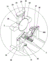
FIG. 1 is a perspective view of the present invention;
FIG. 2 is an enlarged, fragmentary, perspective view of the present invention;
fig. 3 is a perspective view of the components of the present invention.
Detailed Description
The technical solutions in the embodiments of the present invention will be clearly and completely described below with reference to the drawings in the embodiments of the present invention, and it is obvious that the described embodiments are only a part of the embodiments of the present invention, and not all of the embodiments. All other embodiments, which can be derived by a person skilled in the art from the embodiments given herein without making any creative effort, shall fall within the protection scope of the present invention.
Referring to fig. 1-3, the present invention provides a technical solution:
the utility model provides a trunk automatic cutout device, including chassis 1 be equipped with the shutdown mechanism 2 that can cut off the trunk on chassis 1 be equipped with on chassis 1 and carry the conveying mechanism 3 of 2 below shutdown mechanisms with the trunk 1 one end of chassis is equipped with the feed mechanism 4 that can push into conveying mechanism 3 with the trunk, impels conveying mechanism 3 with the trunk through being equipped with feed mechanism 4, carries 2 below shutdown mechanisms with the trunk through conveying mechanism 3, cuts the segmentation through shutdown mechanism 2 to the trunk, whole process automation does not need the staff, and the manpower resources of significantly reducing has improved efficiency, has reduced dangerous emergence, and simple structure, convenient to use.
The feeding mechanism 4 comprises a bracket 40 arranged at the feeding end of the underframe 1, a first trunk cavity 41 is arranged on the bracket 40, a trunk cabin 42 is arranged beside the bracket 40, a chute 43 capable of allowing a single trunk to roll into the first trunk cavity 41 is arranged in the trunk cabin 42, an electric push rod 44 is arranged on the bracket 40, the electric push rod 44 and the first trunk cavity 41 are coaxially arranged, and automatic feeding can be realized by arranging the feeding mechanism.
According to the invention, the underframe 1 is provided with the second trunk cavity 5, the second trunk cavity 5 is connected with the first trunk cavity 41, the plurality of conveying mechanisms 3 are arranged on the second trunk cavity 5 at intervals, and a trunk in the first trunk cavity 41 can move to the second trunk cavity 5.
The conveying mechanism 3 of the invention comprises a through groove 30 symmetrically arranged on a second trunk cavity 5, a support rod 31 is arranged at the position of the underframe 1 corresponding to the through groove 30, a first roller 32 is arranged at the upper end of the support rod 31, a second electric push rod 33 is arranged at the position of the underframe 1 corresponding to the support rod 31, a push block 34 is arranged at the push rod end of the second electric push rod 33, a transverse shaft 35 is inserted in the push block 34, a support frame 36 is arranged at the position of the second trunk cavity 5 corresponding to the second electric push rod 33, a connecting rod 37 is hinged on the support frame 36, a first notch 38 and a second notch 39 are respectively arranged at the two ends of the connecting rod 37, the first notch 38 is movably sleeved on the transverse shaft 35, a guide groove 300 is arranged on the support frame 36, a moving block 301 is movably arranged on the guide groove 300, support plates 302 are arranged on the moving block 301 at intervals, be equipped with second gyro wheel 303 between the backup pad 302, one of them be equipped with first motor 304 on the backup pad 302 outside be connected with second gyro wheel 303 on the motor shaft of first motor 304, another be equipped with connecting block 305 on the backup pad 302 outside be equipped with second backup pad 306 at connecting block 305 interval be equipped with second cross axle 307 between the second backup pad 306, second notch 39 activity cover is established on second cross axle 307, moves second gyro wheel 303 through second electric putter 33 and compresses tightly the trunk, makes the trunk remove through second gyro wheel 303, carries the below of cutting mechanism to the trunk and cuts.
The cutting mechanism 2 comprises a second support frame 20 arranged at the front end of an underframe 1, a cover plate 23 is arranged above the second support frame 20, a vertical shaft 21 and a screw 22 are respectively arranged between the cover plate 23 and the second support frame 20, a second moving block 24 is sleeved on the vertical shaft 21, the second moving block 24 is in threaded connection with the screw 22, a second motor 25 is arranged on the cover plate 23, a motor shaft of the second motor 25 is connected with one end of the screw 22, a saw blade cutting machine 26 is arranged on the second moving block 24, and the second motor 25 drives the screw 22 to rotate, so that the saw blade cutting machine 26 moves up and down to cut a trunk.
The controller 50 is arranged on the outer side of the underframe 1, the controller 50 is respectively and electrically connected with the electric push rod 44, the second electric push rod 33, the first motor 304, the second motor 25 and the saw blade cutting machine 26, and the controller 50 is used for controlling the cutting mechanism 2, the conveying mechanism 3 and the feeding mechanism 4 to work.
While there have been shown and described the fundamental principles and principal features of the invention and advantages thereof, it will be understood by those skilled in the art that the invention is not limited by the embodiments described above, which are given by way of illustration of the principles of the invention, but is susceptible to various changes and modifications without departing from the spirit and scope of the invention as defined by the appended claims. The scope of the invention is defined by the appended claims and equivalents thereof.