CN108370619B - Microwave oven with a heat exchanger - Google Patents
Microwave oven with a heat exchanger Download PDFInfo
- Publication number
- CN108370619B CN108370619B CN201780004503.8A CN201780004503A CN108370619B CN 108370619 B CN108370619 B CN 108370619B CN 201780004503 A CN201780004503 A CN 201780004503A CN 108370619 B CN108370619 B CN 108370619B
- Authority
- CN
- China
- Prior art keywords
- cooking chamber
- food
- tray
- microwave oven
- reflecting
- Prior art date
- Legal status (The legal status is an assumption and is not a legal conclusion. Google has not performed a legal analysis and makes no representation as to the accuracy of the status listed.)
- Expired - Fee Related
Links
- 238000010411 cooking Methods 0.000 claims abstract description 253
- 235000013305 food Nutrition 0.000 claims abstract description 205
- 230000005855 radiation Effects 0.000 claims abstract description 71
- 238000000034 method Methods 0.000 claims description 21
- 239000011810 insulating material Substances 0.000 claims description 4
- 238000005192 partition Methods 0.000 claims description 4
- 230000005672 electromagnetic field Effects 0.000 description 10
- 238000010438 heat treatment Methods 0.000 description 7
- 238000001514 detection method Methods 0.000 description 6
- 239000000463 material Substances 0.000 description 4
- 230000005540 biological transmission Effects 0.000 description 3
- 238000001816 cooling Methods 0.000 description 3
- 230000007423 decrease Effects 0.000 description 3
- 238000010521 absorption reaction Methods 0.000 description 2
- 239000003990 capacitor Substances 0.000 description 2
- 230000000694 effects Effects 0.000 description 2
- 230000005670 electromagnetic radiation Effects 0.000 description 2
- 150000001875 compounds Chemical class 0.000 description 1
- 238000010586 diagram Methods 0.000 description 1
- 239000000428 dust Substances 0.000 description 1
- 235000013399 edible fruits Nutrition 0.000 description 1
- 230000005684 electric field Effects 0.000 description 1
- 238000005265 energy consumption Methods 0.000 description 1
- 238000013213 extrapolation Methods 0.000 description 1
- 230000002349 favourable effect Effects 0.000 description 1
- 239000011521 glass Substances 0.000 description 1
- 230000005484 gravity Effects 0.000 description 1
- 238000005259 measurement Methods 0.000 description 1
- 235000013372 meat Nutrition 0.000 description 1
- 238000003801 milling Methods 0.000 description 1
- 238000000465 moulding Methods 0.000 description 1
- 239000000126 substance Substances 0.000 description 1
- 235000013311 vegetables Nutrition 0.000 description 1
- XLYOFNOQVPJJNP-UHFFFAOYSA-N water Substances O XLYOFNOQVPJJNP-UHFFFAOYSA-N 0.000 description 1
Images


Classifications
-
- H—ELECTRICITY
- H05—ELECTRIC TECHNIQUES NOT OTHERWISE PROVIDED FOR
- H05B—ELECTRIC HEATING; ELECTRIC LIGHT SOURCES NOT OTHERWISE PROVIDED FOR; CIRCUIT ARRANGEMENTS FOR ELECTRIC LIGHT SOURCES, IN GENERAL
- H05B6/00—Heating by electric, magnetic or electromagnetic fields
- H05B6/64—Heating using microwaves
- H05B6/72—Radiators or antennas
- H05B6/725—Rotatable antennas
-
- H—ELECTRICITY
- H05—ELECTRIC TECHNIQUES NOT OTHERWISE PROVIDED FOR
- H05B—ELECTRIC HEATING; ELECTRIC LIGHT SOURCES NOT OTHERWISE PROVIDED FOR; CIRCUIT ARRANGEMENTS FOR ELECTRIC LIGHT SOURCES, IN GENERAL
- H05B6/00—Heating by electric, magnetic or electromagnetic fields
- H05B6/64—Heating using microwaves
- H05B6/6408—Supports or covers specially adapted for use in microwave heating apparatus
-
- H—ELECTRICITY
- H05—ELECTRIC TECHNIQUES NOT OTHERWISE PROVIDED FOR
- H05B—ELECTRIC HEATING; ELECTRIC LIGHT SOURCES NOT OTHERWISE PROVIDED FOR; CIRCUIT ARRANGEMENTS FOR ELECTRIC LIGHT SOURCES, IN GENERAL
- H05B6/00—Heating by electric, magnetic or electromagnetic fields
- H05B6/64—Heating using microwaves
- H05B6/6402—Aspects relating to the microwave cavity
-
- H—ELECTRICITY
- H05—ELECTRIC TECHNIQUES NOT OTHERWISE PROVIDED FOR
- H05B—ELECTRIC HEATING; ELECTRIC LIGHT SOURCES NOT OTHERWISE PROVIDED FOR; CIRCUIT ARRANGEMENTS FOR ELECTRIC LIGHT SOURCES, IN GENERAL
- H05B6/00—Heating by electric, magnetic or electromagnetic fields
- H05B6/64—Heating using microwaves
- H05B6/6408—Supports or covers specially adapted for use in microwave heating apparatus
- H05B6/6411—Supports or covers specially adapted for use in microwave heating apparatus the supports being rotated
-
- H—ELECTRICITY
- H05—ELECTRIC TECHNIQUES NOT OTHERWISE PROVIDED FOR
- H05B—ELECTRIC HEATING; ELECTRIC LIGHT SOURCES NOT OTHERWISE PROVIDED FOR; CIRCUIT ARRANGEMENTS FOR ELECTRIC LIGHT SOURCES, IN GENERAL
- H05B6/00—Heating by electric, magnetic or electromagnetic fields
- H05B6/64—Heating using microwaves
- H05B6/6447—Method of operation or details of the microwave heating apparatus related to the use of detectors or sensors
-
- H—ELECTRICITY
- H05—ELECTRIC TECHNIQUES NOT OTHERWISE PROVIDED FOR
- H05B—ELECTRIC HEATING; ELECTRIC LIGHT SOURCES NOT OTHERWISE PROVIDED FOR; CIRCUIT ARRANGEMENTS FOR ELECTRIC LIGHT SOURCES, IN GENERAL
- H05B6/00—Heating by electric, magnetic or electromagnetic fields
- H05B6/64—Heating using microwaves
- H05B6/72—Radiators or antennas
-
- H—ELECTRICITY
- H05—ELECTRIC TECHNIQUES NOT OTHERWISE PROVIDED FOR
- H05B—ELECTRIC HEATING; ELECTRIC LIGHT SOURCES NOT OTHERWISE PROVIDED FOR; CIRCUIT ARRANGEMENTS FOR ELECTRIC LIGHT SOURCES, IN GENERAL
- H05B6/00—Heating by electric, magnetic or electromagnetic fields
- H05B6/64—Heating using microwaves
- H05B6/74—Mode transformers or mode stirrers
-
- H—ELECTRICITY
- H05—ELECTRIC TECHNIQUES NOT OTHERWISE PROVIDED FOR
- H05B—ELECTRIC HEATING; ELECTRIC LIGHT SOURCES NOT OTHERWISE PROVIDED FOR; CIRCUIT ARRANGEMENTS FOR ELECTRIC LIGHT SOURCES, IN GENERAL
- H05B6/00—Heating by electric, magnetic or electromagnetic fields
- H05B6/64—Heating using microwaves
- H05B6/78—Arrangements for continuous movement of material
- H05B6/782—Arrangements for continuous movement of material wherein the material moved is food
Abstract
Disclosed herein is a microwave oven having an improved structure through which food can be efficiently heated. The microwave oven includes: a housing including a cooking chamber having a bottom surface; at least one first reflection part formed on a bottom surface of the cooking chamber; a magnetron arranged to generate microwave radiation; and a tray disposed spaced apart from a bottom surface of the cooking chamber and supporting food to be heated. The at least one first reflective portion protrudes to a predetermined height (h) above a Reference Level (RL).
Description
Technical Field
Embodiments of the present invention relate generally to microwave ovens, and more particularly, to a microwave oven having an improved structure with which food can be efficiently heated.
Background
A microwave oven is a cooker that heats food using the characteristics of electromagnetic radiation called microwaves. The microwave oven generates heat from the inside of the food by dielectric heating to heat the food.
When electromagnetic radiation with a high frequency penetrates into the food, it causes the water polar molecules inside the food to rotate, and it generates thermal energy. The food is heated in the microwave oven due to this energy consumption.
The quality of food cooked by the microwave oven is determined according to the degree of uniformity of the temperature distribution inside the food. In order to make the temperature distribution inside the food uniform, the microwaves should be uniformly applied to the entire food.
Therefore, research into a method by which microwaves can be uniformly applied to food is being actively conducted.
Disclosure of Invention
Technical problem
An aspect of the present invention provides a microwave oven having an improved structure by which food can be uniformly heated.
Another aspect of the present invention provides a microwave oven having an improved structure by which a cooking time can be reduced.
Additional aspects of the invention will be set forth in part in the description which follows, and in part will be obvious from the description, or may be learned by practice of the invention.
Solution to the problem
According to an aspect of the present invention, a microwave oven includes: a housing including a cooking chamber having a bottom surface; at least one first reflection part formed on a bottom surface of the cooking chamber; a magnetron arranged to generate microwave radiation; and a tray disposed spaced apart from a bottom surface of the cooking chamber and supporting food to be heated. The at least one first reflective portion extends to a predetermined height (h) above a Reference Level (RL).
The distance between the tray and the highest point of the at least one first reflective portion may be less than λ/4, where λ is the minimum wavelength of the microwave radiation.
The height (h) of the at least one first reflective portion may be less than λ/4 and the cross-sectional area (S) of the at least one first reflective portion may be less than hx λ/4.
The at least one first reflection part may be integrally formed with a bottom surface of the cooking chamber.
The height (h) and/or width (w) of the at least one first reflection part may vary based on a method of operating the microwave oven according to the weight, type and initial state of food.
The height (h) and/or width (w) of the at least one first reflective portion may be automatically changed by the elastic body corresponding to the weight of the food.
The height (h) and/or the width (w) of the at least one first reflective portion may be mechanically varied according to a manual selection by a user.
The distance between the tray and the bottom surface of the cooking chamber may be automatically changed by the spring damper corresponding to the weight of the food.
The distance between the tray and the bottom surface of the cooking chamber may be changed according to manual selection by a user.
The at least one first reflective portion may serve as a guide for a wheel that supports the tray and rotates about a rotational axis of the tray, wherein the rotational axis of the tray passes through a geometric center of the bottom surface of the cooking chamber.
The at least one first reflective portion may have a closed loop shape and may have a symmetrical structure with respect to a plane including a rotation axis (X) of the tray, wherein the rotation axis (X) of the tray passes through a geometric center (O) of the bottom surface of the cooking chamber.
The at least one first reflective portion may have a rotational symmetry structure with respect to a plane including a rotational axis (X) of the tray, wherein the rotational axis (X) of the tray passes through a geometric center (O) of the bottom surface of the cooking chamber.
The at least one first reflective portion may have a mirror-symmetrical structure with respect to a plane including a rotation axis (X) of the tray, wherein the rotation axis (X) of the tray passes through a geometric center (O) of the bottom surface of the cooking chamber.
The at least one first reflective portion may have a plurality of symmetrical structures.
The at least one first reflective portion may have an asymmetric structure.
The tray may be disposed spaced apart from a bottom surface of the cooking chamber, and may be disposed to be rotatable.
The portion of the bottom surface of the cooking chamber comprising the at least one first reflective portion may be arranged to be rotatable about a vertical axis (Y) passing through a geometric center (O) of the bottom surface of the cooking chamber.
The food may be supported by a non-rotating tray formed of an insulating material.
According to another aspect of the present invention, a microwave oven includes: a housing including a cooking chamber having a bottom surface; at least one second reflection part formed on a bottom surface of the cooking chamber; a magnetron arranged to generate microwave radiation; and a tray disposed spaced apart from a bottom surface of the cooking chamber and supporting food to be heated. At least one second reflecting portion is recessed below the Reference Level (RL) by a given depth (d).
The distance between the tray and the highest point of the bottom surface of the cooking chamber may be less than λ/4, where λ is the minimum wavelength of the microwave radiation.
The depth (d) of the at least one second reflective portion may be less than λ/4 and the cross-sectional area (S) of the at least one second reflective portion may be less than dxλ/4.
The at least one second reflection part may be integrally formed with the bottom surface of the cooking chamber.
The depth (d) and/or width (w) of the at least one second reflecting portion may vary depending on the weight, type and initial state of the food based on the method of operating the microwave oven.
The depth (d) and/or width (w) of the at least one second reflective portion may be automatically changed by the elastic body corresponding to the weight of the food.
The depth (d) and/or width (w) of the at least one second reflective portion may be mechanically varied according to a manual selection by a user.
The distance between the tray and the bottom surface of the cooking chamber may be automatically changed by the spring damper corresponding to the weight of the food.
The distance between the tray and the bottom surface of the cooking chamber may be changed according to manual selection by a user.
The at least one second reflective portion may serve as a guide for a wheel supporting the tray and rotating about a rotational axis (X) of the tray, wherein the rotational axis (X) of the tray passes through a geometric center (O) of the bottom surface of the cooking chamber.
The at least one second reflective portion may have a closed loop shape and may have a symmetrical structure with respect to a plane including a rotation axis (X) of the tray, wherein the rotation axis (X) of the tray passes through a geometric center (O) of the bottom surface of the cooking chamber.
The at least one second reflective portion may have a rotational symmetry structure with respect to a plane including a rotational axis (X) of the tray, wherein the rotational axis (X) of the tray passes through a geometric center (O) of the bottom surface of the cooking chamber.
The at least one second reflective portion may have a mirror-symmetrical structure with respect to a plane including a rotational axis (X) of the tray, wherein the rotational axis (X) of the tray passes through a geometric center (O) of the bottom surface of the cooking chamber.
The at least one second reflective portion may have a variety of symmetrical structures.
The at least one second reflective portion may have an asymmetric structure.
The tray may be disposed spaced apart from a bottom surface of the cooking chamber, and may be disposed to be rotatable.
The portion of the bottom surface of the cooking chamber comprising the at least one second reflective portion may be arranged to be rotatable about a vertical axis (Y) passing through a geometric center (O) of the bottom surface of the cooking chamber.
The food may be supported by a non-rotating tray formed of an insulating material.
The invention has the advantages of
At least one first reflection part is formed on the bottom surface of the cooking chamber so that the food is uniformly heated by the microwave radiation reflected from the bottom surface of the cooking chamber.
At least one second reflection part is formed in the bottom surface of the cooking chamber so that the food is uniformly heated by the microwave radiation reflected from the bottom surface of the cooking chamber.
The distance between the bottom surface of the cooking chamber and the tray is adjusted according to the type or weight of the food, and thus the cooking time of the food can be reduced.
At least one of the first and second reflecting portions is formed on the bottom surface of the cooking chamber, thereby allowing the food to be uniformly heated regardless of the type of magnetron or a cooking algorithm (e.g., cooking time).
Drawings
These and/or other aspects of the invention will become apparent and more readily appreciated from the following description of the embodiments, taken in conjunction with the accompanying drawings of which:
fig. 1 is a perspective view illustrating an exterior of a microwave oven according to an embodiment of the present invention;
fig. 2 is a view schematically illustrating a process of heating food by microwave radiation when the microwave oven according to the embodiment of the present invention is operated;
fig. 3a and 3b are views for theoretically describing the shape of a pattern formed on the bottom of a cooking chamber in a microwave oven according to an embodiment of the present invention;
fig. 4a is a sectional view illustrating a first bottom surface of a cooking chamber in a microwave oven according to an embodiment of the present invention;
fig. 4b is a graph showing the degree to which food cooked in the cooking chamber to which the first bottom surface of fig. 4a is applied is heated;
fig. 4c is a sectional view illustrating a second bottom surface of a cooking chamber in a microwave oven according to an embodiment of the present invention;
fig. 4d is a graph showing the degree to which food cooked in the cooking chamber to which the second bottom surface of fig. 4c is applied is heated;
fig. 4e is a sectional view illustrating a third bottom surface of a cooking chamber in a microwave oven according to an embodiment of the present invention;
fig. 4f is a graph showing the degree to which food cooked in the cooking chamber to which the third bottom surface of fig. 4e is applied is heated;
fig. 4g is a sectional view illustrating a fourth bottom surface of a cooking chamber in a microwave oven according to an embodiment of the present invention;
fig. 4h is a graph showing the degree to which food cooked in the cooking chamber to which the fourth bottom surface of fig. 4g is applied is heated;
fig. 5a is a sectional view illustrating a cooking chamber in a microwave oven according to an embodiment of the present invention, on the bottom surface of which a pattern according to the first embodiment is formed;
fig. 5b is a sectional view illustrating a cooking chamber in a microwave oven according to an embodiment of the present invention, on the bottom surface of which a pattern according to the second embodiment is formed;
fig. 5c is a sectional view illustrating a cooking chamber in a microwave oven according to an embodiment of the present invention, on the bottom surface of which a pattern according to a third embodiment is formed;
fig. 6a to 6f are diagrams illustrating various patterns that may be formed on the bottom surface of a cooking chamber in a microwave oven according to an embodiment of the present invention;
fig. 7a is a view illustrating a cooking chamber in a microwave oven according to an embodiment of the present invention, on the bottom surface of which a pattern according to a fourth embodiment is formed;
fig. 7b is a view illustrating a cooking chamber in a microwave oven according to an embodiment of the present invention, on the bottom surface of which a pattern according to a fifth embodiment is formed;
fig. 7c is a view illustrating a cooking chamber in a microwave oven according to an embodiment of the present invention, on the bottom surface of which a pattern according to a sixth embodiment is formed;
fig. 7d is a view illustrating a cooking chamber in a microwave oven according to an embodiment of the present invention, on the bottom surface of which a pattern according to a seventh embodiment is formed;
fig. 8a to 8d are views illustrating a relationship between a wheel and a cooking chamber having various patterns formed on a bottom surface thereof in a microwave oven according to an embodiment of the present invention;
fig. 9a is a view illustrating a cooking chamber in a microwave oven according to an embodiment of the present invention, on the bottom surface of which a variable pattern according to an eighth embodiment is formed;
fig. 9b is a view illustrating a cooking chamber in a microwave oven according to an embodiment of the present invention, on the bottom surface of which a variable pattern according to a ninth embodiment is formed;
fig. 10a to 10c are views illustrating a process in which a variable pattern according to a tenth embodiment is operated in a microwave oven according to an embodiment of the present invention;
fig. 11a and 11b are views illustrating a process in which a variable pattern according to an eleventh embodiment is operated in a microwave oven according to an embodiment of the present invention;
fig. 12a and 12b are views illustrating how the height of the tray is manually adjusted for the initial temperature of food in the microwave oven according to the embodiment of the present invention;
fig. 13 is a view illustrating how the height of a tray is automatically adjusted in the microwave oven according to the embodiment of the present invention;
fig. 14 is a sectional view illustrating a microwave oven according to another embodiment of the present invention; and
fig. 15 is a sectional view illustrating a microwave oven according to other embodiments of the present invention.
Modes for carrying out the invention
Reference will now be made in detail to the embodiments of the present invention, examples of which are illustrated in the accompanying drawings, wherein like reference numerals refer to the like elements throughout. On the other hand, terms such as "front end", "rear end", "upper", "lower end", and the like used in the following description are defined based on the drawings, and the shape and position of the element are not limited by these terms.
The quality of food cooked by the microwave oven may be determined by the degree of uniformity of the temperature distribution inside the food undergoing the cooking process. Generally, when the deviation of the temperature inside the food subjected to the cooking process is small, the user is more satisfied with the result of cooking the food using the microwave oven.
In order to make the temperature distribution inside the food uniform, the electromagnetic field distribution inside the food should be made uniform.
The main problems of the microwave oven are: the food is unevenly heated due to uneven distribution of the electromagnetic field inside the food. When the microwave oven is operated, a specific electromagnetic field distribution is formed in a cooking chamber of the microwave oven. At this time, a region having a high degree of distribution of the electromagnetic field and a region having a low degree of distribution of the electromagnetic field may be formed in the food, which causes the food to be heated unevenly.
Generally, food can be uniformly heated by forming a uniform electromagnetic field throughout the cooking chamber.
As an example, when a plurality of protrusions are formed on the inner surface of the cooking chamber and there is no depression capable of concentrating microwave radiation on the inner surface of the cooking chamber, the microwave radiation may be effectively dispersed throughout the cooking chamber. However, when food to be cooked is introduced into the cooking chamber, the food introduced into the cooking chamber changes the uniform electromagnetic field distribution to some extent. This can be compensated for by changing the operating frequency of the magnetron. Therefore, simply forming a plurality of protrusions on the inner surface of the cooking chamber is not necessarily sufficient to form a uniform electromagnetic field distribution throughout the cooking chamber.
Hereinafter, a method of efficiently forming a uniform electromagnetic field throughout the cooking chamber, that is, a method of uniformly heating food will be described.
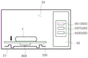
Fig. 1 is a perspective view illustrating an exterior of a microwave oven according to an embodiment of the present invention. Fig. 2 is a view schematically illustrating a process of heating food by microwave radiation when the microwave oven according to the embodiment of the present invention is operated. Fig. 3a and 3b are views for theoretically describing the shape of a pattern formed on the bottom of a cooking chamber in a microwave oven according to an embodiment of the present invention. Hereinafter, the food is denoted by the symbol "F".
As shown in fig. 1 and 2, the microwave oven 1 may include a case 10 forming an exterior. The cooking chamber 20 and the electronic component compartment 30 may be provided in the housing 10, wherein a front surface of the cooking chamber 20 is opened so that food can be put therein, and various electronic components are mounted in the electronic component compartment 30.
The cooking chamber 20 may include a bottom surface 21, a first side surface 22 adjacent to the electronic component compartment 30, a second side surface 23 facing the first side surface 22, a top surface 24 facing the bottom surface 21, and a rear surface (not shown) facing the open front surface. Various types of patterns may be formed on the bottom surface 21 of the cooking chamber 20. The pattern will be described in detail below.
A tray 200 may be installed in the cooking chamber 20, wherein food to be cooked is placed on the tray 200. The tray 200 may be disposed spaced apart from the bottom surface 21 of the cooking chamber 20. The tray 200 can be rotatably installed in the cooking chamber 20. The tray 200 may be rotated by the rotating unit 210 so that the food placed on the tray 200 may be uniformly heated by the microwave radiation. The rotating unit 210 may include a tray motor (not shown) generating a rotational driving force for rotating the tray 200, and the tray motor may be disposed under the cooking chamber 20. The tray 200 may be balanced and rotated by a plurality of wheels 300. In other words, the plurality of wheels 300 serve to rotatably support the tray 200.
A door 40 may be installed at the front of the case 10, wherein one side of the door 40 is hinged such that the cooking chamber 20 can be opened and closed. Further, a control panel 50 may be mounted at the front of the housing 10, wherein the control panel 50 is positioned at the front of the electronic component compartment 30 and is used to operate various electronic components in the electronic component compartment 30.
A magnetron 60 generating microwave radiation to be radiated into the cooking chamber 20, and a high voltage transformer 70, a high voltage capacitor 80, a high voltage diode 90, etc. constituting a driving circuit for driving the magnetron 60 may be mounted in the electronic component compartment 30. Behind the electronic component compartment 30, a cooling fan 100 for absorbing outdoor air to cool various electronic components in the electronic component compartment 30 may be installed.
The microwave oven 1 operates as follows. When food is placed in the cooking chamber 20 and the microwave oven 1 is operated by the control panel 50, power supply is applied to the high voltage transformer 70 and is started by the high voltage transformer 70. The power supply is doubled again by the high voltage capacitor 80 and the high voltage diode 90 and transmitted to the magnetron 60. The magnetron 60 receives a high voltage and generates microwave radiation to radiate it into the cooking chamber 20. The food is cooked in the cooking chamber 20 by microwave radiation.
On the other hand, when the microwave oven 1 is operated, the cooling fan 100 for cooling heat generated by the magnetron 60 or the high voltage transformer 70 is operated, and thus an air flow for circulating outdoor air into the electronic component compartment 30 is generated.
In order to uniformly heat the food located in cooking chamber 20, uniform transmission of microwave radiation to the food is required. The microwave radiation radiated from the magnetron 60 into the cooking chamber 20 may be directly transmitted to the food or may be transmitted to the food through the inner wall of the cooking chamber 20. As shown in fig. 2, since most of the microwave radiation is transmitted to the food through the inner wall of the cooking chamber 20, the state of the inner wall of the cooking chamber 20 may have a great influence on the transmission of the microwave radiation to the food. In particular, since the bottom surface 21 of the cooking chamber 20 is closest to the food to be cooked, it has the greatest effect on the transmission of microwave radiation to the food. In other words, the distribution of microwave radiation transmitted to the food may depend on the state of the bottom surface 21 of the cooking chamber 20.
A pattern may be formed on the bottom surface 21 of the cooking chamber 20 so that microwave radiation reflected from the bottom surface 21 of the cooking chamber 20 may be uniformly transmitted to the food.
The pattern may be integrally formed with the bottom surface 21 of the cooking chamber 20. Specifically, at least one of the at least one first reflecting portion 110 and the at least one second reflecting portion 120 may be integrally formed with the bottom surface 21 of the cooking chamber 20.
The pattern may be formed on the bottom surface 21 of the cooking chamber 20 by at least one of stamping, molding, and milling.
The pattern may include at least one of the first and second reflective portions 110 and 120. In other words, the pattern may include at least one of the at least one first reflective portion 110 and the at least one second reflective portion 120. The first reflecting portion 110 may have a shape protruding above the reference level RL from the bottom surface 21 of the cooking chamber 20. In other words, the first reflecting portion 110 may have a shape extending from the bottom surface 21 of the cooking chamber 20 to above the reference level RL at a given height h. On the other hand, the first reflective portion 110 may be closer to the tray 200 than the second reflective portion 120. Accordingly, the first reflecting portion 110 can transmit a relatively large amount of heating source (i.e., microwave radiation) to the food on the tray 200 due to its proximity to the food. The first reflective portion 110 may include an uneven shape. As will be described below, the first reflection part 110 may include an uneven shape having a plurality of areas. The second reflecting portion 120 may have a shape recessed below the reference level RL from the bottom surface 21 of the cooking chamber 20. In other words, the second reflecting portion 120 may have a shape recessed below the reference level RL from the bottom surface 21 of the cooking chamber 20 by a given depth d. On the other hand, the second reflective portion 120 may be farther from the tray 200 than the first reflective portion 110. Accordingly, the second reflecting portion 120 may transmit a relatively small amount of heating source (i.e., microwave radiation) to the food as it is away from the food on the tray 200. The second reflective portion 120 may include an uneven shape. As will be described below, the second reflection part 120 may include an uneven shape having a plurality of areas. The bottom surface 21 of the cooking chamber 20 may be a flat surface forming the bottom of the cooking chamber 20. The reference horizontal plane RL refers to an imaginary surface including the bottom surface 21 and a surface extending from the bottom surface 21 in the horizontal direction. On the other hand, the reference level RL refers to an imaginary flat surface including the boundary where the bottom surface 21 of the cooking chamber 20 intersects the opposite side surface of the cooking chamber 20. Reference level RL may be illustrated as a planar form in which a first interface a at which bottom surface 21 of cooking chamber 20 intersects first side surface 22 of cooking chamber 20 and a second interface B at which bottom surface 21 of cooking chamber 20 intersects second side surface 23 of cooking chamber 20 are connected in two-dimensional side surfaces. At least one of the first and second reflecting parts 110 and 120 is formed on the bottom surface 21 of the cooking chamber 20, and thus the distribution of microwave radiation transmitted from the bottom surface 21 of the cooking chamber 20 to food can be adjusted. Specifically, the first reflecting portion 110 reduces the distance between the food and the bottom surface 21 of the cooking chamber 20, so that the intensity of the microwave radiation transmitted to the food can be increased. In addition, the second reflecting portion 120 increases the distance between the food and the bottom surface 21 of the cooking chamber 20, so that the intensity of the microwave radiation transmitted to the food can be reduced. In this way, the pattern formed on the bottom surface 21 of the cooking chamber 20 may act as a factor that exerts an important influence on uniform heating of the food caused by microwave radiation.
The height h of the first reflective portion 110, the depth d of the second reflective portion 120, and the cross-sectional area S of the first and second reflective portions 110, 120 may be defined in accordance with the minimum wavelength λ of microwave radiation generated by the magnetron 60. Specifically, the height h of the first reflective part 110 and the depth d of the second reflective part 120 may be less than λ/4. Further, the cross-sectional area S of the second reflective portion 120 may be less than d λ/4. Further, the cross-sectional area S of the first reflective portion 110 may be less than hxλ/4. Hereinafter, a theoretical background of a relationship among the height h of the first reflection part 110, the depth d of the second reflection part 120, the width a of the second reflection part 120, and the width b of the first reflection part 110 will be described in detail. The density p of microwave radiation absorbed by the food at all points of the food can be defined by the Joule-Lenz law. Joule lenz's law is as follows.

In the formula 1, the first and second groups of the compound, indicating the density of the
 bottom surface 21 of the cooking chamber 20, Represents the electric field strength at a specific point of the food, and σ represents the electrical conductivity of the material forming the
 bottom surface 21 of the cooking chamber 20.
Induced electric surface current JsMay be defined according to the following equation 2 according to the boundary condition of the bottom surface 21 of the cooking chamber 20.
Js=Hy2-Hy1=ΔHy(formula 2)
In the formula 2, the first and second groups, representing the tangential component of the magnetic field strength. Thus, the density p of microwave radiation absorbed by the food at all points of the food can be defined according to the
 following equation 3.

Fig. 3a shows an example of a pattern formed on the bottom surface 21 of the cooking chamber 20. In fig. 3a, "RL" denotes a reference level. The tangential component of the magnetic field strength between the bottom surface 21 of the cooking chamber 20 and the food may be defined according to equation 4 based on the height h of the first reflecting portion 110, the depth d of the second reflecting portion 120, the width a of the second reflecting portion 120, and the width b of the first reflecting portion 110.

Accordingly, surface waves between the bottom surface 21 of the cooking chamber 20 and the food may have a tangential component defined by the bottom surface 21 of the cooking chamber 20. The tangential component is defined according to the following equation 5.

In equation 5, α represents the orthogonal power absorption attenuation coefficient. α can be defined according to the following equation 6.

Thus, the density p of microwave radiation absorbed by the food at all points of the food can be varied by varying the absorption attenuation coefficient at particular points of the bottom surface 21 of the cooking chamber 20.
As shown in fig. 3b, the attenuation coefficient α having an effective influence on the electromagnetic field (change of 10% or more of power) may have a relationship of "0.05 < α < 1". For reference, the horizontal axis in fig. 3b represents the sum of the height h of the first reflecting part 110 and the depth d of the second reflecting part 120. The sum of the height h of the first reflective part 110 and the depth d of the second reflective part 120 may be expressed in units of "mm". The vertical axis in fig. 3b represents the attenuation coefficient α. The optimal relationship among the height h of the first reflective part 110, the depth d of the second reflective part 120, the width a of the second reflective part 120, and the width b of the first reflective part 110 may be defined as the following equation 7.λ represents the minimum wavelength of microwave radiation.
(lambda/16 < (h + d) < lambda/8) and (0.5< b/a <2) (equation 7)
The degree of density p of microwave radiation absorbed by the food may be defined in terms of the distance l from the food. As the vertical distance 1 between the first reflecting portion 110 and the food increases, the influence of the bottom surface 21 of the cooking chamber 20 on the temperature distribution inside the food may be reduced. Therefore, the most favorable relationship is "(h + d + l) < λ/4".
In this way, at least one of the first reflecting portions 110 having various heights h and the second reflecting portions 120 having various depths d is applied to the bottom surface 21 of the cooking chamber 20. Thereby, the food can be uniformly heated.
Fig. 4a is a sectional view illustrating a first bottom surface of a cooking chamber in a microwave oven according to an embodiment of the present invention, and fig. 4b is a graph illustrating a degree to which food cooked in the cooking chamber to which the first bottom surface of fig. 4a is applied is heated. The horizontal axis of the graph shown in fig. 4b represents the width (mm) from the center of the food, and the vertical axis represents the density p (W/cm) of microwave radiation absorbed by the food3)。
As shown in fig. 4a and 4b, when the second reflection part 120 is formed in the bottom surface 21 of the cooking chamber 20, food can be almost uniformly heated by microwave radiation. At this time, the depth d of the second reflection part 120 may be less than λ/4. Further, the cross-sectional area S of the second reflective portion 120 may be less than d λ/4.
The graph of fig. 4b is based on the fact that the minimum wavelength lambda of the microwave radiation is about 12cm (lambda/4 is about 3cm), the depth d of the second reflecting portion 120 is 1cm and the cross-sectional area S of the second reflecting portion 120 is 2cm at a frequency of the microwave radiation of 2.45GHz2The condition (2) pushes down the derived result.
The description of fig. 4a and 4b focuses on the case where only the second reflection part 120 is formed in the bottom surface 21 of the cooking chamber 20. However, the tendency of the pattern as shown in fig. 4b may be obtained when at least one of the first and second reflecting portions 110 and 120 is formed at the bottom surface 21 of the cooking chamber 20. Specifically, even when at least one of the first and second reflecting parts 110 and 120 is formed at the bottom surface 21 of the cooking chamber 20, the food can be almost uniformly heated by the microwave radiation. In this case, the height h of the first reflection part 110 may be less than λ/4, and the cross-sectional area S of the first reflection part 110 may be less than hxλ/4. Further, the depth d of the second reflection part 120 may be less than λ/4, and the cross-sectional area S of the second reflection part 120 may be less than dxλ/4.
Fig. 4c is a sectional view illustrating a second bottom surface of a cooking chamber in a microwave oven according to an embodiment of the present invention, and fig. 4d is a graph illustrating a degree to which food cooked in the cooking chamber to which the second bottom surface of fig. 4c is applied is heated. The horizontal axis of the graph shown in fig. 4d represents the width (mm) from the center of the food, and the vertical axis represents the density p (W/cm) of microwave radiation absorbed by the food3)。
As shown in fig. 4c and 4d, when the second reflection part 120 is formed in the bottom surface 21 of the cooking chamber 20, the food may be unevenly heated by the microwave radiation. At this time, the depth d of the second reflection part 120 may be less than λ/4. Further, the cross-sectional area S of the second reflective portion 120 may be greater than d λ/4.
The graph of FIG. 4d is based on the fact that the minimum wavelength λ of the microwave radiation is about 12cm (λ/4 is about 3cm), the depth d of the second reflecting portion 120 is 1cm and the cross-sectional area S of the second reflecting portion 120 is 6cm at the frequency of the microwave radiation being 2.45GHz2The condition (2) is the result of the extrapolation.
As can be seen from the graph of fig. 4d, the density of microwave radiation absorbed in the center of the food is still higher than the density of microwave radiation absorbed at other areas of the food. Therefore, it is difficult to expect the food to be uniformly heated under the condition that the depth d of the second reflecting portion 120 is less than λ/4 and the sectional area S of the second reflecting portion 120 is greater than dxλ/4.
The description of fig. 4c and 4d focuses on the case where only the second reflection part 120 is formed on the bottom surface 21 of the cooking chamber 20. However, even when at least one of the first and second reflecting parts 110 and 120 is formed at the bottom surface 21 of the cooking chamber 20, it is difficult to expect the food to be uniformly heated. In this case, the height h of the first reflection part 110 may be less than λ/4, and the cross-sectional area S of the first reflection part 110 may be greater than hxλ/4. Further, the depth d of the second reflection part 120 may be less than λ/4, and the cross-sectional area S of the second reflection part 120 may be greater than dxλ/4.
Fig. 4e is a sectional view illustrating a third bottom surface of a cooking chamber in a microwave oven according to an embodiment of the present invention, and fig. 4f is a sectional view illustrating a degree to which food cooked in the cooking chamber to which the third bottom surface of fig. 4e is applied is heated. The horizontal axis of the graph shown in fig. 4f represents the width (mm) from the center of the food, and the vertical axis represents the density p (W/cm) of microwave radiation absorbed by the food3)。
As shown in fig. 4e and 4f, when the second reflection part 120 is formed in the bottom surface 21 of the cooking chamber 20, the food may be unevenly heated by the microwave radiation. At this time, the depth d of the second reflection part 120 may be greater than 4/λ. Further, the cross-sectional area S of the second reflective portion 120 may be less than d λ/4.
The graph of fig. 4f is based on the fact that the minimum wavelength lambda of the microwave radiation is about 12cm (lambda/4 is about 3cm), the depth d of the second reflecting portion 120 is 3cm and the cross-sectional area S of the second reflecting portion 120 is 4cm at a frequency of the microwave radiation of 2.45GHz2The condition (2) pushes down the derived result.
As can be seen from the graph of fig. 4f, the density of microwave radiation absorbed in the center of the food is lower than the density of microwave radiation absorbed at other areas of the food. Therefore, it is difficult to expect the food to be uniformly heated under the condition that the depth d of the second reflecting portion 120 is greater than λ/4 and the sectional area S of the second reflecting portion 120 is less than dxλ/4.
The description of fig. 4e and 4f focuses on the case where only the second reflection part 120 is formed in the bottom surface 21 of the cooking chamber 20. However, even when at least one of the first and second reflecting parts 110 and 120 is formed at the bottom surface 21 of the cooking chamber 20, it is difficult to expect the food to be uniformly heated. In this case, the height h of the first reflection part 110 may be greater than λ/4, and the cross-sectional area S of the first reflection part 110 may be less than hxλ/4. Further, the depth d of the second reflection part 120 may be greater than λ/4, and the cross-sectional area S of the second reflection part 120 may be less than dxλ/4.
Fig. 4g is a sectional view illustrating a fourth bottom surface of a cooking chamber in a microwave oven according to an embodiment of the present invention, and fig. 4h is a graph illustrating a degree to which food cooked in the cooking chamber to which the fourth bottom surface of fig. 4g is applied is heated. The horizontal axis of the graph shown in fig. 4h represents the width (mm) from the center of the food, and the vertical axis represents the density p (W/cm) of microwave radiation absorbed by the food3)。
As shown in fig. 4g and 4h, when the second reflection part 120 is formed in the bottom surface 21 of the cooking chamber 20, the food may be unevenly heated by the microwave radiation. At this time, the depth d of the second reflection part 120 may be greater than λ/4. Further, the cross-sectional area S of the second reflective portion 120 may be greater than d λ/4.
The graph of FIG. 4h is based on the fact that the minimum wavelength λ of the microwave radiation is about 12cm (λ/4 is about 3cm), the depth d of the second reflecting portion 120 is 3cm and the cross-sectional area S of the second reflecting portion 120 is 15cm at the frequency of the microwave radiation being 2.45GHz2The condition (2) pushes down the derived result.
As can be seen from the graph of fig. 4h, the density of microwave radiation absorbed in the center of the food is lower than the density of microwave radiation absorbed at other areas of the food. The graph of fig. 4h has a trend similar to that of the graph of fig. 4 f. However, as can be seen from a comparison between the graph of fig. 4f and the graph of fig. 4h, the waveforms of the graphs are different from each other. Therefore, it is difficult to expect the food to be uniformly heated under the condition that the depth d of the second reflecting portion 120 is greater than λ/4 and the sectional area S of the second reflecting portion 120 is greater than dxλ/4.
The description of fig. 4g and 4h focuses on the case where only the second reflection part 120 is formed in the bottom surface 21 of the cooking chamber 20. However, even when at least one of the first and second reflecting parts 110 and 120 is formed at the bottom surface 21 of the cooking chamber 20, it is difficult to expect the food to be uniformly heated. In this case, the height h of the first reflection part 110 may be greater than λ/4, and the cross-sectional area S of the first reflection part 110 may be greater than hxλ/4. Further, the depth d of the second reflection part 120 may be greater than λ/4, and the cross-sectional area S of the second reflection part 120 may be greater than dxλ/4.
In summary, as shown in fig. 4a and 4b, under the condition that the depth d of the second reflecting portion 120 is less than λ/4 and the sectional area S of the second reflecting portion 120 is less than d × λ/4, it can be expected that the food is uniformly heated. Such an effect can also be expected when at least one of the first and second reflecting portions 110 and 120 is formed at the bottom surface 21 of the cooking chamber 20. In this case, the height h of the first reflection part 110 may be less than λ/4, and the cross-sectional area S of the first reflection part 110 may be less than hxλ/4. Further, the depth d of the second reflection part 120 may be less than λ/4, and the cross-sectional area S of the second reflection part 120 may be less than dxλ/4.
Fig. 5a is a sectional view illustrating a cooking chamber in a microwave oven according to an embodiment of the present invention, wherein a pattern according to the first embodiment is formed on a bottom surface of the cooking chamber. Fig. 5b is a sectional view illustrating a cooking chamber in a microwave oven according to an embodiment of the present invention, wherein a pattern according to the second embodiment is formed on a bottom surface of the cooking chamber. Fig. 5c is a sectional view illustrating a cooking chamber in a microwave oven according to an embodiment of the present invention, in which a pattern according to a third embodiment is formed on a bottom surface of the cooking chamber. Fig. 5a shows the bottom surface 21 of the cooking chamber 20 on which a concentric second reflecting portion 120 is formed. Fig. 5b shows the bottom surface 21 of the cooking chamber 20 on which a concentric first reflective portion 110 is formed. Fig. 5c illustrates the bottom surface 21 of the cooking chamber 20 on which both the second reflecting portion 120 and the first reflecting portion 110 are formed.
The depth d of the second reflecting portion 120 represents the degree to which it is recessed from the reference level RL, and the height h of the first reflecting portion 110 represents the degree to which it is raised from the reference level RL. The sectional areas S of the first and second reflecting portions 110 and 120 may be defined based on the sections of the first and second reflecting portions 110 and 120 when the microwave oven 1 is taken along the line I-I' of fig. 1. Taking the microwave oven 1 along the line I-I' of fig. 1 means taking the microwave oven 1 along an imaginary plane passing through the geometric center O of the bottom surface 21 of the cooking chamber 20 and perpendicular to the bottom surface 21 of the cooking chamber 20. Here, the geometric center O of the bottom surface 21 of the cooking chamber 20 may refer to the center of gravity of the bottom surface 21 of the cooking chamber 20. As an example, in case of the microwave oven 1 having the rotatable tray 200, the geometric center O of the bottom surface 21 of the cooking chamber 20 may refer to a portion of the bottom surface 21 of the cooking chamber 20 that is penetrated by the rotation axis X of the tray 200. In fig. 5a to 5c, the sectional area S of the second reflection part 120 may be defined by the product of the width w1 of the second reflection part 120 and the depth d of the second reflection part 120, and the sectional area S of the first reflection part 110 may be defined by the product of the width w2 of the first reflection part 110 and the height h of the first reflection part 110.
As shown in fig. 5a, the second reflective portion 120 may be recessed below the reference level RL. Further, the depth d of the second reflective portion 120 may be less than λ/4. Further, the cross-sectional area S of the second reflective portion 120 may be less than d λ/4. Further, a distance k1 between the highest point of the bottom surface 21 of the cooking chamber 20 and the tray 200 may be less than λ/4.
As shown in fig. 5b, the first reflective portion 110 may protrude above the reference level RL. Further, the height h of the first reflective portion 110 may be less than λ/4. Further, the cross-sectional area S of the first reflective portion 110 may be less than hxλ/4. Further, a distance k2 between the first reflection part 110 formed on the bottom surface 21 of the cooking chamber 20 and the tray 200 may be less than λ/4. Specifically, a distance k2 between the highest point of the first reflection part 110 formed on the bottom surface 21 of the cooking chamber 20 and the tray 200 may be less than λ/4.
As shown in fig. 5c, the second reflective portion 120 may be recessed below the reference level RL and the first reflective portion 110 may be projected above the reference level RL. The description of the depth d and the sectional area S of the second reflecting part 120 and the distance k1 between the highest point of the bottom surface 21 of the cooking chamber 20 and the tray 200 is the same as that of fig. 5a, and the description of the height h and the sectional area S of the first reflecting part 110 and the distance k2 between the highest point of the first reflecting part 110 and the tray 200 is the same as that of fig. 5b, and thus the descriptions will be omitted.
Fig. 6a to 6f are sectional views illustrating various patterns that may be formed on the bottom surface of the cooking chamber in the microwave oven according to the embodiment of the present invention. Fig. 6a to 6c are views illustrating various shapes of the second reflection part 120 formed on the bottom surface 21 of the cooking chamber 20. Fig. 6d to 6f are views illustrating various shapes of the first reflection part 110 formed on the bottom surface 21 of the cooking chamber 20. In fig. 6a to 6f, the same reference numerals are given to elements having the same names. "RL" represents a reference level.
As shown in fig. 6a, the second reflection part 120 may include a first space 121, a second space 122, and a third space 123 having different depths. The depth d1 of the first space 121, the depth d2 of the second space 122, and the depth d3 of the third space 123 may be less than λ/4. Further, the sectional area S1 of the first space 121, the sectional area S2 of the second space 122, and the sectional area S3 of the third space 123 may be less than d × λ/4. The cross-sectional area S1 of the first space 121 is defined as the product of the depth d1 of the first space 121 and the width a1 of the first space 121. The sectional area S2 of the second space 122 is defined as the product of the depth d2 of the second space 122 and the width a2 of the second space 122. The sectional area S3 of the third space 123 is defined as the product of the depth d3 of the third space 123 and the width a3 of the third space 123.
As shown in fig. 6b, the second reflective part 120 may include a first space 121, a second space 122, and a third space 123 having different depths. The second space 122 may be recessed from the reference horizontal plane RL to a very small extent compared to the adjacent first and third spaces 121 and 123. The depth d1 of the first space 121, the depth d2 of the second space 122, and the depth d3 of the third space 123 may be less than λ/4. Further, the sectional area S1 of the first space 121, the sectional area S2 of the second space 122, and the sectional area S3 of the third space 123 may be less than d × λ/4. The width a2 of the second space 122 may be greater than the width a1 of the first space 121 and the width a3 of the third space 123.
As shown in fig. 6c, the second reflective part 120 may include a first space 121 and a second space 122 having different depths. The depth d1 of the first space 121 and the depth d2 of the second space 122 may be less than λ/4. Further, the sectional area S1 of the first space 121 and the sectional area S2 of the second space 122 may be less than d × λ/4. Assuming that the first space 121 and the second space 122 have a trapezoidal shape, the cross-sectional area S1 of the first space 121 may be defined according to the formula "the cross-sectional area S1 of the first space 121 { (first width a1) + (second width a1') } × the depth d1 × 1/2 of the first space 121". Further, the cross-sectional area S2 of the second space 122 may be defined in terms of "the cross-sectional area S2 of the second space 122 { (first width a2) + (second width a2') } × the depth d2 × 1/2 of the second space 122". The first space 121 and the second space 122 may be spaced apart from each other by a given distance.
As shown in fig. 6d, the first reflective part 110 may include a first region 111, a second region 112, and a third region 113 having different heights. The height h1 of the first region 111, the height h2 of the second region 112, and the height h3 of the third region 113 may be less than λ/4. Further, the cross-sectional area S1 of the first region 111, the cross-sectional area S2 of the second region 112, and the cross-sectional area S3 of the third region 113 may be less than h × λ/4. The width a2 of the second region 112 may be greater than the width a1 of the first region 111 and the width a3 of the third region 113.
As shown in fig. 6e, the first reflective part 110 may include a first region 111, a second region 112, and a third region 113 having different heights. The height h1 of the first region 111, the height h2 of the second region 112, and the height h3 of the third region 113 may be less than λ/4. In particular, the height h2 of the second region 112 may be less than the heights h1 and h3 of the adjacent first and third regions 111 and 113. Further, the cross-sectional area S1 of the first region 111, the cross-sectional area S2 of the second region 112, and the cross-sectional area S3 of the third region 113 may be less than h × λ/4.
As shown in fig. 6f, the first reflective part 110 may include a first region 111 and a second region 112 having different heights. The height h1 of the first region 111 and the height h2 of the second region 112 may be less than λ/4. Further, the cross-sectional area S1 of the first region 111 and the cross-sectional area S2 of the second region 112 may be less than h λ/4. Assuming that the first and second regions 111 and 112 have a trapezoidal shape, the cross-sectional area S1 of the first region 111 may be defined according to the formula "cross-sectional area S1 of the first region 111 { (first width a1) + (second width a1') } × height h1 × 1/2 of the first region 111". The cross-sectional area S2 of the second region 112 may be defined according to the formula "cross-sectional area S2 of the second region 112 { (first width a2) + (second width a2') } × height h2 × 1/2 of the second region 112". The first region 111 and the second region 112 may be spaced apart from each other by a predetermined distance.
How to solve the cross-sectional area when the second reflection portion 120 has a quadrangular shape in fig. 6a and when the first reflection portion 110 has a trapezoidal shape in fig. 6f has been described in detail. At least one of the shapes of the first and second reflection parts 110 and 120 is not limited to the quadrangular shape and the trapezoidal shape, but may be variously changed. As an example, at least one of the shapes of the first and second reflective portions 110 and 120 may include a curved surface. The method of solving for at least one of the cross-sectional areas of the first and second reflective portions 110, 120 may depend on the respective shapes.
Fig. 7a is a view illustrating a cooking chamber in a microwave oven according to an embodiment of the present invention, on the bottom surface of which a pattern according to the fourth embodiment is formed. Fig. 7b is a view illustrating a cooking chamber in a microwave oven according to an embodiment of the present invention, on the bottom surface of which a pattern according to the fifth embodiment is formed. Fig. 7c is a view illustrating a cooking chamber in a microwave oven according to an embodiment of the present invention, on the bottom surface of which a pattern according to a sixth embodiment is formed. Fig. 7d is a view illustrating a cooking chamber in a microwave oven according to an embodiment of the present invention, on the bottom surface of which a pattern according to the seventh embodiment is formed.
As shown in fig. 7a, a pattern having a symmetrical structure may be formed on the bottom surface 21 of the cooking chamber 20. Specifically, at least one of the first and second reflection parts 110 and 120 may be formed in the shape of a closed loop having a symmetrical structure. As an example, at least one of the first and second reflection parts 110 and 120 may be formed in the shape of a plurality of circles having the same center as the geometric center O of the bottom surface 21 of the cooking chamber 20 and increasing in diameter toward the outside of the bottom surface 21 of the cooking chamber 20. At least one of the first and second reflecting parts 110 and 120 may have a concentric circular relationship, the center of which is the same as the geometric center O of the bottom surface 21 of the cooking chamber 20. On the other hand, at least one of the first and second reflecting portions 110 and 120 may have a symmetrical structure with respect to a plane including the rotation axis X of the tray 200, wherein the rotation axis X of the tray 200 passes through the geometric center O of the bottom surface 21 of the cooking chamber 20.
As shown in fig. 7b, a pattern having a mirror-symmetrical structure may be formed on the bottom surface 21 of the cooking chamber 20. Specifically, at least one of the first and second reflecting portions 110 and 120 may have a mirror-symmetrical structure with respect to a plane including the rotation axis X of the tray 200, wherein the rotation axis X of the tray 200 passes through the geometric center O of the bottom surface 21 of the cooking chamber 20.
As shown in fig. 7c, a pattern having a rotational symmetric structure may be formed on the bottom surface 21 of the cooking chamber 20. Specifically, at least one of the first and second reflecting portions 110 and 120 may have a rotationally symmetric structure with respect to a plane including the rotation axis X of the tray 200, wherein the rotation axis X of the tray 200 passes through the geometric center O of the bottom surface 21 of the cooking chamber 20.
As shown in fig. 7d, a pattern mixing a plurality of symmetrical structures may be formed on the bottom surface 21 of the cooking chamber 20. As an example, the pattern in which a plurality of symmetrical structures are mixed may be a pattern in which a symmetrical structure of a closed loop shape shown in fig. 7a and a mirror-symmetrical structure shown in fig. 7b are mixed. However, the type of pattern mixing a plurality of symmetric structures is not limited to the above example. As shown in fig. 7d, at least one of the first and second reflecting portions 110 and 120 may have a symmetrical structure with respect to a plane including the rotation axis X of the tray 200, wherein the rotation axis X of the tray 200 passes through the geometric center O of the bottom surface 21 of the cooking chamber 20.
The pattern formed on the bottom surface 21 of the cooking chamber 20 may have an asymmetrical structure in addition to the symmetrical structure. As an example, when the plurality of second reflecting parts 120 and the plurality of first reflecting parts 110 are formed on the bottom surface 21 of the cooking chamber 20, at least one of the plurality of second reflecting parts 120 or at least one of the plurality of first reflecting parts 110 may be formed in an asymmetric structure.
Fig. 8a to 8d are views illustrating a relationship between a wheel and a cooking chamber having various patterns formed on a bottom surface thereof in a microwave oven according to an embodiment of the present invention. The wheel shown in fig. 8a and 8c is referred to as a first wheel 301 and the wheel shown in fig. 8b and 8d is referred to as a second wheel 302.
As shown in fig. 8a to 8d, a pattern formed on the bottom surface 21 of the cooking chamber 20 may be used to guide the wheel 300 rotatably supporting the tray 200. In other words, at least one of the first and second reflecting portions 110 and 120 formed on the bottom surface 21 of the cooking chamber 20 may be used to guide the wheel 300 for supporting the tray 200, which rotates about the rotational axis X (see fig. 7a) of the tray 200, wherein the rotational axis X of the tray 200 passes through the geometric center O of the bottom surface 21 of the cooking chamber 20.
As shown in fig. 8a, the first wheel 301 can rotatably support the tray 200 in a state where it is coupled to the first reflection portion 110 projected above the reference level RL.
As shown in fig. 8b, the second wheel 302 can rotatably support the tray 200 in a state where it is positioned on the first reflecting portion 110 projected above the reference horizontal plane RL. In addition to this, the second wheel 302 can rotatably support the tray 200 in a state where it is accommodated between the plurality of first reflecting portions 110 projected above the reference horizontal plane RL.
As shown in fig. 8c, the first wheel 301 can rotatably support the tray 200 in a state where it is coupled to the second reflection part 120 recessed below the reference level RL.
As shown in fig. 8d, the second wheel 302 can rotatably support the tray 200 in a state where it is positioned on the second reflecting portion 120 recessed below the reference level RL. In addition to this, the second wheel 302 can rotatably support the tray 200 in a state where it is accommodated between the plurality of first reflecting portions 110 projected above the reference horizontal plane RL.
Fig. 9a is a view illustrating a cooking chamber in a microwave oven according to an embodiment of the present invention, on the bottom surface of which a variable pattern according to an eighth embodiment is formed, and fig. 9b is a view illustrating a cooking chamber in a microwave oven according to an embodiment of the present invention, on the bottom surface of which a variable pattern according to a ninth embodiment is formed. Fig. 9a and 9b show a bottom surface 21 of the cooking chamber 20 in which the width of the pattern is variable. Specifically, fig. 9a illustrates the bottom surface 21 of the cooking chamber 20 in which the width of the second reflection part 120 is variable, and fig. 9b illustrates the bottom surface 21 of the cooking chamber 20 in which the width of the first reflection part 110 is variable. "RL" represents a reference level.
The width w1 of the second reflecting portion 120 and the width w2 of the first reflecting portion 110 may vary depending on the type, weight, initial state, etc. of food based on the method of operating the microwave oven 1.
Specifically, the width w1 of the second reflection part 120 or the width w2 of the first reflection part 110 may be automatically changed by the elastic body corresponding to the weight of the food or the like. In addition to this, the width w1 of the second reflective portion 120 or the width w2 of the first reflective portion 110 can be mechanically changed according to a manual selection made by a user. In addition to this, the width w1 of the second reflection part 120 or the width w2 of the first reflection part 110 may be changed by a hydraulic or pneumatic cylinder corresponding to the weight of food or the like.
As shown in fig. 9a, the width w1 of the second reflective portion 120 is mechanically variable. As an example, a plurality of movable units 400 may be installed in the bottom surface 21 of the cooking chamber 20. The plurality of movable units 400 may be installed in the partitions 28 defining the second reflection part 120 so as to be movable in a horizontal direction. When the plurality of movable units 400 move from the partition 28 toward the second reflection portion 120, the width w1 of the second reflection portion 120 decreases. In contrast, when the plurality of movable units 400 protruding to the inside of the second reflection portion 120 are moved toward the partition 28, the width w1 of the second reflection portion 120 is increased.
As shown in fig. 9b, the width w2 of the first reflective portion 110 is mechanically variable. As an example, a plurality of movable units 400 may be installed in the bottom surface 21 of the cooking chamber 20. A plurality of movable units 400 may be installed in the first reflection part 110 so as to be movable in a horizontal direction. When the plurality of movable units 400 move toward the outside of the first reflection portion 110, the width w2 of the first reflection portion 110 increases. In contrast, when the plurality of movable units 400 move toward the inside of the first reflection portion 110, the width w2 of the first reflection portion 110 decreases.
Since such a variable pattern is formed on the bottom surface 21 of the cooking chamber 20, the food can be uniformly heated regardless of the kind or weight of the food.
Fig. 10a to 10c are views illustrating a process in which a variable pattern according to a tenth embodiment is operated in a microwave oven according to an embodiment of the present invention. Fig. 10a to 10c show the process of the change of the depth d of the second reflection part 120. "RL" represents a reference level.
The depth d of the second reflecting portion 120 may vary depending on the type, weight, initial state, etc. of the food based on the method of operating the microwave oven 1.
Specifically, the depth d of the second reflection part 120 may be automatically changed by the elastic body corresponding to the weight of the food, etc. In addition to this, the depth d of the second reflective portion 120 may be mechanically changed according to a manual selection made by a user. In addition to this, the depth d of the second reflecting portion 120 may be changed by a hydraulic or pneumatic cylinder corresponding to the weight of food, etc.
As shown in fig. 10a to 10c, the depth d of the second reflective portion 120 is mechanically variable. As an example, the movable unit 400 may be installed in the bottom surface 21 of the cooking chamber 20. According to circumstances, the movable unit 400 may define a bottom surface of the second reflection part 120, and may be installed to be movable in a horizontal direction. Fig. 10a and 10b illustrate a case where the movable unit 400 defines a bottom surface of the second reflection part 120. As an example, the movable unit 400 may be mounted to be movable in a vertical direction using an elastic body such as a spring. Since such a variable pattern is formed on the bottom surface 21 of the cooking chamber 20, the food can be uniformly heated regardless of the kind or weight of the food. Fig. 10a shows the case where the depth d of the second reflection part 120 is the deepest. Fig. 10b shows a case where the depth d of the second reflection part 120 is reduced by the upward movement of the movable unit 400. By comparing fig. 10a and 10b, it can be seen that the depth d of the second reflection part 120 is further reduced in fig. 10b than in fig. 10a by the upward movement of the movable unit 400. Fig. 10c shows the situation where the movable unit 400 is moved upwards until it is level with the reference level RL and the second reflecting portion 120 disappears. Although fig. 10a to 10c illustrate a case where one movable unit 400 is installed in the bottom surface 21 of the cooking chamber 20, a plurality of movable units 400 may be installed in the bottom surface 21 of the cooking chamber 20. At this time, the plurality of movable units 400 may move up and down independently of each other.
The width w1 and the depth d of the second reflective portion 120 can be varied simultaneously.
Fig. 11a and 11b are views illustrating a process in which a variable pattern according to an eleventh embodiment is operated in a microwave oven according to an embodiment of the present invention. Fig. 11a and 11b show different embodiments of varying the height h of the first reflective portion 110. "RL" represents a reference level.
The height h of the first reflecting portion 110 may vary depending on the type, weight, initial state, etc. of the food based on the method of operating the microwave oven 1.
Specifically, the height h of each of the first reflection parts 110 may be automatically changed by the elastic body corresponding to the weight of the food, etc. In addition to this, the height h of each of the first reflective portions 110 may be mechanically changed according to a manual selection made by a user. In addition to this, the height h of each of the first reflecting portions 110 may be changed by a hydraulic or pneumatic cylinder corresponding to the weight of food or the like.
As shown in fig. 11a and 11b, the height h of each of the first reflective portions 110 is mechanically variable. As an example, a guide portion 29 may be formed in the bottom surface 21 of the cooking chamber 20, wherein each of the first reflection portions 110 is movable at the guide portion 29. The guide part 29 may have a groove shape deeply cut in the bottom surface 21 of the cooking chamber 20 in a vertical direction such that each of the first reflection parts 110 is movable. The first reflecting portion 110 is movable in the vertical direction along the guide portion 29. As an example, the first reflection part 110 can be vertically moved along the guide part 29 by an elastic body such as a spring. When the first reflection part 110 moves upward along the guide part 29, the height h of the first reflection part 110 increases. In contrast, when the first reflection part 110 moves downward along the guide part 29, the height h of the first reflection part 110 decreases. Since such a variable pattern is formed on the bottom surface 21 of the cooking chamber 20, the food can be uniformly heated regardless of the kind or weight of the food.
As shown in fig. 11a, the plurality of first reflecting portions 110 formed on the bottom surface 21 of the cooking chamber 20 can move in an interlocking manner. In other words, the heights h of the plurality of first reflection portions 110 can be changed as a whole.
Further, as shown in fig. 11b, the plurality of first reflection parts 110 formed on the bottom surface 21 of the cooking chamber 20 can move independently of each other. In other words, the heights h of the plurality of first reflective portions 110 may be independently varied.
Both the width w2 and the height h of the first reflective portion 110 can be varied simultaneously.
Fig. 12a and 12b are views illustrating how the height of the tray is manually adjusted according to the initial temperature of the food in the microwave oven according to the embodiment of the present invention. Fig. 12a and 12b illustrate a case where the height of the tray 200 is manually adjusted by the user according to the state of the food. At least one adjustment button 500 may be formed on the control panel 50. Reference numeral 800 of fig. 12a and 12b denotes a "tray support". The tray support 800 supports the tray 200 and can move in the vertical direction at the same time. The tray support 800 may include a spring damper, a pneumatic cylinder, or the like.
The height of the tray 200 may be changed according to the state of the food placed on the tray 200. The state of the food includes the type of the food, the weight of the food, the density of the food, the initial temperature of the food, and the like.
As shown in fig. 12a and 12b, the height of the tray 200 may be manually adjusted according to the initial temperature of the food placed on the tray 200. As shown in fig. 12a, when the initial temperature of the food is low, the distance between the bottom surface 21 of the cooking chamber 20 and the tray 200 is reduced. In other words, the height of the tray 200 is reduced. Here, when the initial temperature of the food is lower than-15 ℃, the initial temperature of the food is referred to as low. As shown in fig. 12b, when the initial temperature of the food is high, the distance between the bottom surface 21 of the cooking chamber 20 and the tray 200 is increased. In other words, the height of the tray 200 is increased. This is because, when the initial temperature of the food is lower, it takes longer to heat the food. By reducing the distance between the tray 200 and the bottom surface 21 of the cooking chamber 20, microwave radiation reflected from the bottom surface 21 of the cooking chamber 20 can be more efficiently transmitted to the food.
When the user wants to manually adjust the height of the tray 200 according to the initial temperature of the food, the user may select the first adjustment button 501. If the user selects the first adjustment button 501, a temperature detection sensor (not shown) for food is operated to measure the temperature of the food. The height of the tray 200 is adjusted according to the result.
In addition, the height of the tray 200 may be manually adjusted according to the density of food placed on the tray 200. When the density of the food is low, the distance between the bottom surface 21 of the cooking chamber 20 and the tray 200 is increased. In other words, the height of the tray 200 is increased. When the density of the food is high, the distance between the bottom surface 21 of the cooking chamber 20 and the tray 200 is reduced. In other words, the height of the tray 200 is reduced. This is because it takes longer to heat the food when the density of the food is higher. By reducing the distance between the tray 200 and the bottom surface 21 of the cooking chamber 20, microwave radiation reflected from the bottom surface 21 of the cooking chamber 20 can be more efficiently transmitted to the food.
When the user wants to manually adjust the height of the tray 200 according to the density of the food, the user may select the second adjustment button 502. If the user selects the second adjustment button 502, a density detection sensor (not shown) for food is operated to measure the density of the food. The height of the tray 200 is adjusted according to the result.
The low-density food may include, for example, fruits or vegetables. The high-density food may, for example, comprise meat.
In addition, the height of the tray 200 may be manually adjusted according to the weight of food placed on the tray 200. When the weight of the food is small, the distance between the bottom surface 21 of the cooking chamber 20 and the tray 200 is increased. In other words, the height of the tray 200 is increased. When the weight of the food is large, the distance between the bottom surface 21 of the cooking chamber 20 and the tray 200 is reduced. In other words, the height of the tray 200 is reduced. This is because it takes longer to heat the food when the weight of the food is large. By reducing the distance between the tray 200 and the bottom surface 21 of the cooking chamber 20, microwave radiation reflected from the bottom surface 21 of the cooking chamber 20 can be more efficiently transmitted to the food.
When the user wants to manually adjust the height of the tray 200 according to the weight of the food, the user may select the third adjustment button 503. If the user selects the third adjustment button 503, a weight detection sensor (not shown) for food is operated to measure the weight of the food. The height of the tray 200 is adjusted according to the result.
When the user selects the adjustment button 500, not only the height of the tray 200 but also the width, height, depth, etc. of the pattern can be adjusted.
Fig. 13 is a view illustrating how the height of a tray is automatically adjusted in the microwave oven according to the embodiment of the present invention. Fig. 13 shows a case where the spring damper 600 is applied as an example.
As shown in fig. 13, the height of the tray 200 may be changed according to the state of the food placed on the tray 200. The state of the food includes the type of the food, the weight of the food, the density of the food, the initial temperature of the food, and the like.
The distance between the bottom surface 21 of the cooking chamber 20 and the tray 200 is increased when the weight of the food is small, when the density of the food is low, or when the initial temperature of the food is high. In other words, the height of the tray 200 is increased. In contrast, when the weight of the food is large, when the density of the food is high, or when the initial temperature of the food is low, the distance between the bottom surface 21 of the cooking chamber 20 and the tray 200 is reduced. In other words, the height of the tray 200 is reduced. This is because, when the weight of the food is large, the density of the food is high, or the initial temperature of the food is low, it takes longer to heat the food. By reducing the distance between the tray 200 and the bottom surface 21 of the cooking chamber 20, microwave radiation reflected from the bottom surface 21 of the cooking chamber 20 can be more efficiently transmitted to the food.
The height of the tray 200 may be automatically adjusted according to the state of the food. At this time, as an example, the height of the tray 200 may be adjusted using the spring damper 600.
At least one of a camera and a sensor capable of measuring the state of food may be installed in the microwave oven 1. As an example, at least one of a camera and a sensor may be installed in the cooking chamber 20. The sensors may include temperature detection sensors, density detection sensors, weight detection sensors, and the like. Fig. 13 shows a case where the camera 70 is installed in the cooking chamber 20 as an example.
When the user places food on the tray 200 and operates the microwave oven 1, at least one of the camera and the sensor measures the state of the food. When the measurement of the state of the food is completed, the height of the tray 200 is automatically adjusted according to the result. At this time, not only the height of the tray 200 but also the width, height, depth, etc. of the pattern may be automatically adjusted.
Fig. 14 is a sectional view illustrating a microwave oven according to another embodiment of the present invention. Hereinafter, repetition of the description of fig. 1 to 13 will be omitted.
As shown in fig. 14, the tray 200 may be fixed in the cooking chamber 20. The tray 200 may be formed of an insulating material.
A pattern including at least one of the first and second reflecting portions 110 and 120 may be formed on the bottom surface 21 of the cooking chamber 20. A portion 21a of the bottom surface 21 of the cooking chamber 20 can be rotatably mounted. Specifically, the portion 21a of the bottom surface 21 of the cooking chamber 20 may be mounted to be rotatable about a vertical axis Y passing through the geometric center O of the bottom surface 21 of the cooking chamber 20. A pattern including at least one of the first and second reflection parts 110 and 120 may be formed at a portion 21a of the bottom surface 21 of the cooking chamber 20.
Fig. 15 is a sectional view illustrating a microwave oven according to other embodiments of the present invention. Hereinafter, repetition of the description of fig. 1 to 13 will be omitted.
As shown in fig. 15, the microwave oven 1 may further include a board 900.
The plate 900 may be formed of a material that is transparent to microwave radiation. As an example, the plate 900 may be formed of a glass material.
The plate 900 may be disposed between the tray 200 and at least a portion of the bottom surface 21 of the cooking chamber 20. Specifically, the plate 900 may be disposed between the tray 200 and the bottom surface 21 of the cooking chamber 20 on which at least one of the first and second reflecting portions 110 and 120 is formed.
On the other hand, the plate 900 may be disposed above the bottom surface 21 of the cooking chamber 20. Specifically, the plate 900 may be disposed between the tray 200 and the bottom surface 21 of the cooking chamber 20 on which at least one of the first and second reflecting portions 110 and 120 is formed.
Fig. 15 shows, as an example, a case where the plate 900 is disposed on the bottom surface 21 of the cooking chamber 20 on which the second reflecting portion 120 is formed. In this case, the plurality of wheels 300 rotatably supporting the tray 200 may move on the plate 900.
In this way, the plate 900 is disposed between the tray 200 and the bottom surface 21 of the cooking chamber 20 on which at least one of the first and second reflecting portions 110 and 120 is formed. Thereby, at least one of the first and second reflection parts 110 and 120 can be prevented from being contaminated by foreign substances. The foreign materials may include dust, food, and the like.
A plurality of plates 900 may be disposed between the tray 200 and at least a portion of the bottom surface 21 of the cooking chamber 20.
In the above, food is an example of an object that can be heated by microwave radiation.
Although particular embodiments of the present invention have been shown and described, it would be appreciated by those skilled in the art that changes may be made in these embodiments without departing from the principles and spirit of the invention, the scope of which is defined in the claims and their equivalents.
Claims (14)
1. A microwave oven, comprising:
a housing including a cooking chamber having a bottom surface;
a magnetron arranged to generate microwave radiation;
at least one first reflective portion formed on a bottom surface of the cooking chamber, the at least one first reflective portion reflecting the microwave radiation;
a tray disposed spaced apart from a bottom surface of the cooking chamber, the tray supporting food to be heated by the microwave radiation; and
a plurality of wheels rotatably supporting the tray and supported by the bottom surface,
wherein the at least one first reflective portion protrudes from the bottom surface above a reference level relative to the bottom surface,
wherein the at least one first reflective portion is formed on the bottom surface and between the plurality of wheels.
2. The microwave oven of claim 1, wherein a distance between the tray and a highest point of the at least one first reflective portion is less than λ/4, where λ is a minimum wavelength of the microwave radiation.
3. The microwave oven of claim 2, wherein a height h of the at least one first reflecting portion is less than λ/4, and a cross-sectional area of the at least one first reflecting portion perpendicular to a bottom surface of the cooking chamber is less than hxλ/4.
4. The microwave oven of claim 1, wherein the at least one first reflecting portion is integrally formed with a bottom surface of the cooking chamber.
5. The microwave oven of claim 1, wherein at least one of a height h and a width of the at least one first reflecting portion varies depending on a method of operating the microwave oven according to a weight, a type and an initial state of the food.
6. The microwave oven of claim 1, wherein a distance between the tray and the bottom surface of the cooking chamber is changed corresponding to a weight of the food or is changed according to a manual selection made by a user.
7. The microwave oven of claim 1, wherein the at least one first reflecting portion has a closed ring shape and a symmetrical structure with respect to a plane including a rotational axis of the tray, which passes through a geometric center of the bottom surface of the cooking chamber.
8. The microwave oven of claim 1, wherein the at least one first reflecting portion has at least one structure selected from:
a structure rotationally symmetrical with respect to a plane including a rotational axis of the tray, wherein the rotational axis of the tray passes through a geometric center of a bottom surface of the cooking chamber, an
A structure that is mirror symmetric with respect to a plane including a rotational axis of the tray, wherein the rotational axis of the tray passes through a geometric center of a bottom surface of the cooking chamber.
9. The microwave oven of claim 1, wherein the tray is formed of an insulating material.
10. A microwave oven, comprising:
a housing including a cooking chamber having a bottom surface;
a magnetron arranged to generate microwave radiation;
at least one second reflecting portion formed on a bottom surface of the cooking chamber, the at least one second reflecting portion reflecting the microwave radiation;
a tray disposed to be spaced apart from a bottom surface of the cooking chamber, the tray supporting food to be heated by the microwave radiation,
wherein the at least one second reflective portion is recessed from the bottom surface below a reference level relative to the bottom surface,
wherein a width of the at least one second reflecting portion is varied based on a method of operating the microwave oven according to a weight, a type and an initial state of the food.
11. The microwave oven of claim 10, wherein a distance between the tray and a highest point of the bottom surface of the cooking chamber is less than λ/4, where λ is a minimum wavelength of the microwave radiation.
12. The microwave oven of claim 11, wherein a depth d of the at least one second reflecting portion is less than λ/4, and a cross-sectional area of the at least one second reflecting portion perpendicular to a bottom surface of the cooking chamber is less than dxλ/4.
13. The microwave oven of claim 10, wherein a depth d of the at least one second reflecting portion varies based on a method of operating the microwave oven according to a weight, a type, and an initial state of the food.
14. The microwave oven as claimed in claim 10, wherein a plurality of movable units are installed in a partition defining the at least one second reflecting section so as to be movable in a horizontal direction to vary a width of the at least one second reflecting section.
Applications Claiming Priority (5)
| Application Number | Priority Date | Filing Date | Title |
|---|---|---|---|
| RU2016107376A RU2646616C2 (en) | 2016-03-01 | 2016-03-01 | Microwave oven |
| RURU2016107376 | 2016-03-01 | ||
| KR1020160163264A KR20170102413A (en) | 2016-03-01 | 2016-12-02 | Microwave oven |
| KR10-2016-0163264 | 2016-12-02 | ||
| PCT/KR2017/002209 WO2017150892A1 (en) | 2016-03-01 | 2017-02-28 | Microwave oven |
Publications (2)
| Publication Number | Publication Date |
|---|---|
| CN108370619A CN108370619A (en) | 2018-08-03 |
| CN108370619B true CN108370619B (en) | 2020-12-15 |
Family
ID=59798860
Family Applications (1)
| Application Number | Title | Priority Date | Filing Date |
|---|---|---|---|
| CN201780004503.8A Expired - Fee Related CN108370619B (en) | 2016-03-01 | 2017-02-28 | Microwave oven with a heat exchanger |
Country Status (4)
| Country | Link |
|---|---|
| EP (1) | EP3366082A4 (en) |
| KR (1) | KR20170102413A (en) |
| CN (1) | CN108370619B (en) |
| RU (1) | RU2646616C2 (en) |
Citations (12)
| Publication number | Priority date | Publication date | Assignee | Title |
|---|---|---|---|---|
| US4036151A (en) * | 1972-05-26 | 1977-07-19 | Sharp Kabushiki Kaisha | Microwave cooking apparatus with turntable |
| US4615405A (en) * | 1985-04-16 | 1986-10-07 | Sharp Kabushiki Kaisha | Food weight measuring device for a cooking appliance |
| GB2183980A (en) * | 1985-12-10 | 1987-06-10 | Gold Star Co | Uniform field microwave oven |
| US4683362A (en) * | 1984-09-21 | 1987-07-28 | Yangas Roger A | Reflective apparatus for microwave cooking |
| EP0274164A1 (en) * | 1987-01-08 | 1988-07-13 | Philips Norden AB | A microwave oven |
| US4808781A (en) * | 1988-03-16 | 1989-02-28 | Liu Yiu Ching | Directly driven microwave oven turntable top |
| GB2244193A (en) * | 1990-05-09 | 1991-11-20 | Samsung Electronics Co Ltd | A microwave oven |
| JPH0566019A (en) * | 1991-09-06 | 1993-03-19 | Matsushita Electric Ind Co Ltd | High-frequency heating apparatus |
| CN1083301A (en) * | 1992-08-25 | 1994-03-02 | 株式会社金星社 | The Wave guide system of microwave oven |
| US5828042A (en) * | 1996-07-11 | 1998-10-27 | Lg Electronics Inc. | Uniform heating apparatus for microwave oven and method thereof |
| JP2002327983A (en) * | 2001-05-01 | 2002-11-15 | Anzai Setsu | Microwave drying apparatus |
| CN104853465A (en) * | 2015-04-10 | 2015-08-19 | 云南师范大学 | Microwave oven heating chamber structure equipped with microwave lenses |
Family Cites Families (4)
| Publication number | Priority date | Publication date | Assignee | Title |
|---|---|---|---|---|
| JP3066283B2 (en) * | 1995-03-13 | 2000-07-17 | 三洋電機株式会社 | microwave |
| KR100395559B1 (en) * | 1999-05-29 | 2003-08-25 | 삼성전자주식회사 | Microwave oven having a heater |
| US6674056B2 (en) * | 2001-02-05 | 2004-01-06 | Young Hee Lee | Apparatus for uniforming microwave and heating system using the same |
| US20090139988A1 (en) * | 2007-12-03 | 2009-06-04 | Farnworth Warren M | System for creating more uniform distribution of microwave energy in a cavity |
-
2016
- 2016-03-01 RU RU2016107376A patent/RU2646616C2/en active
- 2016-12-02 KR KR1020160163264A patent/KR20170102413A/en not_active Application Discontinuation
-
2017
- 2017-02-28 EP EP17760296.8A patent/EP3366082A4/en active Pending
- 2017-02-28 CN CN201780004503.8A patent/CN108370619B/en not_active Expired - Fee Related
Patent Citations (12)
| Publication number | Priority date | Publication date | Assignee | Title |
|---|---|---|---|---|
| US4036151A (en) * | 1972-05-26 | 1977-07-19 | Sharp Kabushiki Kaisha | Microwave cooking apparatus with turntable |
| US4683362A (en) * | 1984-09-21 | 1987-07-28 | Yangas Roger A | Reflective apparatus for microwave cooking |
| US4615405A (en) * | 1985-04-16 | 1986-10-07 | Sharp Kabushiki Kaisha | Food weight measuring device for a cooking appliance |
| GB2183980A (en) * | 1985-12-10 | 1987-06-10 | Gold Star Co | Uniform field microwave oven |
| EP0274164A1 (en) * | 1987-01-08 | 1988-07-13 | Philips Norden AB | A microwave oven |
| US4808781A (en) * | 1988-03-16 | 1989-02-28 | Liu Yiu Ching | Directly driven microwave oven turntable top |
| GB2244193A (en) * | 1990-05-09 | 1991-11-20 | Samsung Electronics Co Ltd | A microwave oven |
| JPH0566019A (en) * | 1991-09-06 | 1993-03-19 | Matsushita Electric Ind Co Ltd | High-frequency heating apparatus |
| CN1083301A (en) * | 1992-08-25 | 1994-03-02 | 株式会社金星社 | The Wave guide system of microwave oven |
| US5828042A (en) * | 1996-07-11 | 1998-10-27 | Lg Electronics Inc. | Uniform heating apparatus for microwave oven and method thereof |
| JP2002327983A (en) * | 2001-05-01 | 2002-11-15 | Anzai Setsu | Microwave drying apparatus |
| CN104853465A (en) * | 2015-04-10 | 2015-08-19 | 云南师范大学 | Microwave oven heating chamber structure equipped with microwave lenses |
Also Published As
| Publication number | Publication date |
|---|---|
| CN108370619A (en) | 2018-08-03 |
| EP3366082A1 (en) | 2018-08-29 |
| EP3366082A4 (en) | 2018-12-19 |
| KR20170102413A (en) | 2017-09-11 |
| RU2016107376A (en) | 2017-09-04 |
| RU2646616C2 (en) | 2018-03-06 |
Similar Documents
| Publication | Publication Date | Title |
|---|---|---|
| US10986705B2 (en) | Microwave oven | |
| JP5152971B2 (en) | Cooker | |
| KR100396765B1 (en) | Structure for guiding microwave in microwave oven range | |
| WO2009084170A1 (en) | Cooking device | |
| KR100565656B1 (en) | microwave oven range | |
| KR20070034452A (en) | High speed cooking oven with slot microwave antenna | |
| JPH10106741A (en) | Waveguide system of electronic oven | |
| JP2008241062A5 (en) | ||
| JP2008241062A (en) | Heating cooker | |
| CN108370619B (en) | Microwave oven with a heat exchanger | |
| JP2017053533A (en) | Heating cooker | |
| KR100739158B1 (en) | Uniformly heating apparatus for a microwave oven with a flat table | |
| KR101885654B1 (en) | Cooking apparatus using microwaves | |
| WO2009084171A1 (en) | Cooking device | |
| KR100826702B1 (en) | Oven | |
| JP2005203230A (en) | Heating cooker | |
| KR101543659B1 (en) | Microwave range having a convection function | |
| WO2023074551A1 (en) | Microwave heating device | |
| KR200390575Y1 (en) | A rotating type heater system for microwave oven | |
| JP3910116B2 (en) | High frequency heating device | |
| KR100565655B1 (en) | microwave oven range | |
| JP2010255872A (en) | Heating cooker | |
| KR100593073B1 (en) | Uniform heating system using multi slot | |
| JPH0945472A (en) | High frequency heating device | |
| JP4966648B2 (en) | Microwave heating device |
Legal Events
| Date | Code | Title | Description |
|---|---|---|---|
| PB01 | Publication | ||
| PB01 | Publication | ||
| SE01 | Entry into force of request for substantive examination | ||
| SE01 | Entry into force of request for substantive examination | ||
| GR01 | Patent grant | ||
| GR01 | Patent grant | ||
| CF01 | Termination of patent right due to non-payment of annual fee |
Granted publication date: 20201215 |
|
| CF01 | Termination of patent right due to non-payment of annual fee |