CN108369337B - Image scanning apparatus and method of operating the same - Google Patents
Image scanning apparatus and method of operating the same Download PDFInfo
- Publication number
- CN108369337B CN108369337B CN201680072104.0A CN201680072104A CN108369337B CN 108369337 B CN108369337 B CN 108369337B CN 201680072104 A CN201680072104 A CN 201680072104A CN 108369337 B CN108369337 B CN 108369337B
- Authority
- CN
- China
- Prior art keywords
- jet
- scan
- width
- focus
- spray
- Prior art date
- Legal status (The legal status is an assumption and is not a legal conclusion. Google has not performed a legal analysis and makes no representation as to the accuracy of the status listed.)
- Active
Links
Images


Classifications
-
- H—ELECTRICITY
- H04—ELECTRIC COMMUNICATION TECHNIQUE
- H04N—PICTORIAL COMMUNICATION, e.g. TELEVISION
- H04N1/00—Scanning, transmission or reproduction of documents or the like, e.g. facsimile transmission; Details thereof
- H04N1/024—Details of scanning heads ; Means for illuminating the original
- H04N1/02409—Focusing, i.e. adjusting the focus of the scanning head
-
- G—PHYSICS
- G02—OPTICS
- G02B—OPTICAL ELEMENTS, SYSTEMS OR APPARATUS
- G02B26/00—Optical devices or arrangements for the control of light using movable or deformable optical elements
- G02B26/08—Optical devices or arrangements for the control of light using movable or deformable optical elements for controlling the direction of light
- G02B26/10—Scanning systems
- G02B26/12—Scanning systems using multifaceted mirrors
- G02B26/123—Multibeam scanners, e.g. using multiple light sources or beam splitters
-
- G—PHYSICS
- G02—OPTICS
- G02B—OPTICAL ELEMENTS, SYSTEMS OR APPARATUS
- G02B26/00—Optical devices or arrangements for the control of light using movable or deformable optical elements
- G02B26/08—Optical devices or arrangements for the control of light using movable or deformable optical elements for controlling the direction of light
- G02B26/10—Scanning systems
- G02B26/12—Scanning systems using multifaceted mirrors
- G02B26/127—Adaptive control of the scanning light beam, e.g. using the feedback from one or more detectors
- G02B26/128—Focus control
-
- H—ELECTRICITY
- H04—ELECTRIC COMMUNICATION TECHNIQUE
- H04N—PICTORIAL COMMUNICATION, e.g. TELEVISION
- H04N1/00—Scanning, transmission or reproduction of documents or the like, e.g. facsimile transmission; Details thereof
- H04N1/04—Scanning arrangements, i.e. arrangements for the displacement of active reading or reproducing elements relative to the original or reproducing medium, or vice versa
- H04N1/10—Scanning arrangements, i.e. arrangements for the displacement of active reading or reproducing elements relative to the original or reproducing medium, or vice versa using flat picture-bearing surfaces
- H04N1/1013—Scanning arrangements, i.e. arrangements for the displacement of active reading or reproducing elements relative to the original or reproducing medium, or vice versa using flat picture-bearing surfaces with sub-scanning by translatory movement of at least a part of the main-scanning components
- H04N1/1039—Movement of the main scanning components
- H04N1/1043—Movement of the main scanning components of a sensor array
Landscapes
- Physics & Mathematics (AREA)
- Engineering & Computer Science (AREA)
- Multimedia (AREA)
- Signal Processing (AREA)
- General Physics & Mathematics (AREA)
- Optics & Photonics (AREA)
- Length Measuring Devices By Optical Means (AREA)
- Microscoopes, Condenser (AREA)
- Photometry And Measurement Of Optical Pulse Characteristics (AREA)
Abstract
An image scanning apparatus includes a scan line detector and is configured to image a surface of an object mounted in the image scanning apparatus with a plurality of jets, wherein each jet is formed of a set of scan lines, each scan line being acquired from a corresponding elongated region of the surface of the object extending in a scan width direction using the scan line detector, wherein each set of scan lines is acquired while the object is moved relative to the scan line detector in a scan length direction.
Description
RELATED APPLICATIONS
This application claims priority to U.S. provisional patent application No. 62/265,015 filed on 9/12/2015, which is incorporated by reference in its entirety.
Technical Field
The present application relates to an image scanning apparatus and a method of operating the same.
Background
Fig. 1 illustrates a typical image scanning apparatus providing a virtual microscope, which operates according to known principles.
The image scanning device comprises an imaging lens 1 which focuses light originating from a sample located on a film 6 onto a scan line detector 2. The sample located on the backsheet 6 may be a biological sample, such as a tissue sample.
Since the detector 2 is a scan line detector, the image area is an elongated area 7 extending in the jet width direction 5 (x-axis). The imaging lens 1 and the scan line detector 2 together constitute an imaging system of the image scanning apparatus. The image scanning device typically includes a film mounting arrangement configured to mount the film 6 in the image scanning device.
To produce an elongated image over a large area of the sample located on the negative 6, the negative 6 is moved in the scan length direction 8 (y-axis) relative to the imaging lens 1 and scan line detector 2 (by moving the negative mounting means). In this regard, the sample on the negative is "scanned" by the scan line detector 2.
In more detail, the image scanning apparatus is configured to image the surface of a sample mounted on a base plate 6 with a plurality of jets, wherein each jet is formed by a set of scan lines, each of which is taken using a scan line detector 2 from a respective elongated region 7 extending in a scan width direction 5 of the sample surface, wherein each set of scan lines is taken while the base plate 6 is moved in a scan length direction 8 relative to the scan line detector 2.
The focus setting of the image scanning device can be adjusted, for example, by moving the imaging lens 1 along the imaging axis 9.
In a typical image scanning device, a single jet taken from the sample surface may be about 1mm wide in the jet width direction 5 and 2mm to 60mm long in the jet length direction 8. Multiple jets can be combined to produce an image that is wider than the width of a single jet (about 1 mm).
The inventors have observed that the height variation (z-axis) of a typical biological sample does not typically exceed the depth of focus of the image scanning apparatus (typically within a 1 μm region) at a scale of 1 mm.
Further, the inventors observed that during the acquisition of the spray, the focus setting of the image scanning apparatus can be dynamically adjusted along the length of the sample in the scan length direction 8 (y-axis) to keep the sample in focus. Techniques for measuring and dynamically adjusting to maintain a sample in focus along the length of the sample in the scan length direction 8 are described in the following documents, see, for example, US7485834, WO2013/017855 and US 2014/0071438.
Furthermore, the inventors have observed that it is not known that the height (z-axis) of a biological sample changes more rapidly than the typical amount of 1 μm/mm discussed above. The inventors have also observed that mechanical tolerances in a typical image scanning apparatus indicate that the surface of the biological sample may be tilted (non-parallel) in the scan width direction 5 relative to the imaging plane of the image scanning apparatus. This is not a problem for the scan length direction 8, since the focus of the image scanning device can be dynamically adjusted during the acquisition of the jet as described above. However, the possibility that the height of the biological sample may change more rapidly than the depth of focus of the image scanning apparatus over the width of the jet for the scan width direction 5 is problematic because the focus cannot be dynamically adjusted to bring the jet into focus over its width once.
The present application has been devised in light of the above considerations.
Disclosure of Invention
A first aspect of the present application may provide:
a method of operating an image scanning apparatus;
wherein the image scanning device comprises a scan line detector and is configured to image a surface of an object mounted in the image scanning device in a plurality of jets (swetches), wherein each jet is formed by a set of scan lines, each scan line being acquired using the scan line detector from a respective elongated region of the surface of the object extending in a scan width direction, wherein each set of scan lines is acquired while the object is moved in a scan length direction relative to the scan line detector;
wherein the method comprises:
using at least one scan line acquired from a surface of a first object mounted in an image scanning apparatus using a scan line detector to obtain at least one measurement indicating that the surface of the first object is uneven (e.g., tilted) in a scan width direction relative to an imaging plane of the image scanning apparatus;
setting a spray width value for acquiring at least one spray from a surface of a second object mounted in an image scanning apparatus, wherein the spray width value is set based on the at least one measurement and is configured to keep the/each spray acquired from the surface of the second object substantially in focus on a width of the second object in the scan width direction;
acquiring at least one jet from the surface of the second object using a scan line detector, wherein a width of the at least one jet acquired from the surface of the second object in the scan width direction corresponds to the jet width value set based on the at least one measurement.
It is therefore advantageous that the at least one jet taken from the surface of the second object can substantially maintain a focus on the width of the second object in the scan width direction even when the surface of the second object is uneven (e.g., inclined) in the scan width direction.
For the avoidance of any doubt, the second object may be the same object as the first object, for example a backing sheet (slide) having the sample thereon (see, for example, fig. 8). Alternatively, the second object may be a different object than the first object, e.g., the first object may be an internal target mounted in the image scanning apparatus, and the second object may be a negative with a sample thereon (see, e.g., fig. 6 and 7).
The object may be moved relative to the scan line detector by moving the object while keeping the scan line detector stationary. However, for the avoidance of any doubt, the object may be moved relative to the scan line detector by moving the scan line detector while keeping the object stationary, or by moving both the object and the scan line detector.
One skilled in the art will appreciate that the at least one jet taken from the second object surface may contain a very small local area where the jet is not in focus (e.g., due to local variations in the height of the object surface), even if the jet width value is configured to keep the at least one jet substantially in focus across its width.
The imaging plane of the image scanning device may be defined as the plane from which an image taken by the image scanning device is considered to be in focus. Such a plane may be defined generally for any imaging system.
The at least one measure may indicate that the surface of the first object is tilted in the scan width direction with respect to an imaging plane of the image scanning device.
The at least one metric may be calculated using output values of a focus merit function calculated for at least one scan line at two or more locations that are offset from each other in the beam width direction.
The at least one metric may include at least one difference focus indicating a distance between: (i) a focused horizontal line at a first location on a surface of a first object; and (ii) a focus horizon at a second location on the first object surface; wherein the first position and the second position are offset from each other in the jet width direction.
The first position and the second position shifted from each other in the scan width direction preferably correspond to positions on opposite sides (e.g., opposite ends) of a scan line acquired from a surface of a first object mounted in the image scanning apparatus.
The/each differential focus may be calculated using output values of a focus evaluation function calculated for at least one scan line at two or more positions that are offset from each other in the scan width direction (see, for example, fig. 3 showing output values of the focus evaluation function calculated at two positions for a plurality of scan lines resulting from "focus scanning"; see, for example, also fig. 4 showing output values of the focus evaluation function calculated at four positions for a plurality of scan lines resulting from "focus scanning"; see, for example, also fig. 11 showing output values of the focus evaluation function calculated at two positions for a plurality of scan lines in a beam obtained using the dynamic focus tracking method).
The focus merit function may be configured to provide an indication of focus quality at a given location for at least one scan line and may be calculated based on neighboring pixels at the given location. Such functions are well known in the art.
For the avoidance of any doubt, the at least one measure may comprise a single focus of difference (see, e.g., fig. 3-5), or a plurality of focuses of difference (see, e.g., fig. 11).
If the at least one metric includes a plurality of differential foci, the plurality of differential foci can be combined (e.g., averaged) to provide a combined (e.g., averaged) differential focus, wherein the spray width value is based on the combined (e.g., averaged) differential focus setting.
In some embodiments (see, e.g., fig. 6), before acquiring an image (including a plurality of jets) from a surface of the second object, at least one measurement may be obtained and a jet width value set based on the at least one measurement, wherein a width of each jet in the scan width direction obtained from the surface of the second object corresponds to the jet width value set based on the at least one measurement.
In other embodiments (see, e.g., fig. 7), prior to obtaining each of the jets from the surface of the second object, at least one measurement may be obtained and the jet width value set based on the at least one measurement.
In still other embodiments, at least one measurement may be obtained at periodic intervals, such as once every 30 minutes, and the spray width value may be set based on the at least one measurement.
If the second object is the same object as the first object, the method may include identifying one or more regions on the surface of the object suitable for acquiring at least one scan line, and then acquiring at least one scan line from the one or more identified regions on the surface of the object (for later use in obtaining at least one measurement).
If the method includes acquiring at least one scan line from one or more identified regions on the surface of the object, the corresponding measure indicates that the surface of the first object is not flat (e.g., tilted) in the scan width direction relative to the imaging plane of the image scanning device, and the measure may be acquired for each region on the surface of the object. These metrics may then be combined (e.g., averaged) to provide a combined (e.g., averaged) metric, where the beam width value is set based on the combined (e.g., averaged) metric (see, e.g., fig. 9).
Preferably, the method comprises using a plurality of scan lines to obtain the at least one measurement, the scan lines being acquired from a surface of a first object mounted in the image scanning apparatus using a scan line detector.
In some embodiments, multiple scan lines (from which at least one measurement is obtained) may be taken from a single elongated region of the first object surface that extends in the jet width direction, with the image scanning device having different focus settings, while each scan line is taken (see, e.g., fig. 6-9). The method of acquiring these scan lines may be referred to herein as "focal sweep".
In some embodiments, the plurality of scan lines from which the at least one measurement is obtained may be a set of scan lines forming a spray beam, wherein each scan line is taken from a respective elongated region of the first object surface extending in the scan width direction while moving the first object relative to the scan line detector in the scan length direction (see, e.g., fig. 11-16). The spray formed by the set of scan lines from which the at least one measurement is obtained can be a first spray taken from the surface of the object.
If the plurality of scan lines (from which the at least one measurement is obtained) is a set of scan lines that form a spray, the spray may already be acquired using a dynamic focus tracking method in which the focus setting of the image scanning device is adjusted while the spray is acquired. Such dynamic focusing methods are disclosed, for example, in US7485834, WO2013/017855 and US 2014/0071438.
In some embodiments, the second object may be the same object as the first object, wherein the plurality of scan lines (from which the at least one measurement is obtained) is a set of scan lines that form a spray that has been acquired from the surface of the object using a dynamic focus tracking method in which focus settings of the image scanning device are adjusted while the spray is acquired.
For example, the width of each jet in the scan-width direction subsequently taken from the surface of the object may correspond to a jet width value set based on at least one metric obtained using the set of scan lines forming the jet (see, e.g., fig. 12).
Alternatively, each time a new spray is acquired from the surface of the object, the scan line from which the new spray is formed is used to obtain the at least one measurement, wherein the spray width value is set based on the at least one measurement such that the spray width value is set each time a new spray is acquired (see, e.g., fig. 13 and 14).
In some embodiments, if the spray width value based on the new spray setting acquired from the surface of the object is less than the previously set spray width value used in the new spray acquisition process, the width of the new spray may be reduced based on a smaller spray width value that is already based on the new spray setting (see, e.g., fig. 13 and 14) — which may be accomplished, for example, by scanning a corresponding area on the surface of the object, or by reducing the width of the new spray in a post-process.
In some embodiments, if the spray width value based on the new spray setting obtained from the surface of the object is greater than the previously set spray width value used in the new spray acquisition process, the width of the new spray may be increased based on the greater spray width value that was already based on the new spray setting (see, e.g., fig. 14) — which may be achieved, for example, by scanning the corresponding region on the surface of the object, or by increasing the width of the new spray in post-processing, e.g., by leaving the new spray with a greater width in the spray width direction, preferably with an additional width in the spray width direction from the side of the spray that is not contiguous with the previously obtained spray.
For the avoidance of any doubt, at least one of the metrics need not include a focus of difference.
For example, the at least one metric may include an output value of a focus merit function calculated for at least one scan line at two or more locations that are offset from each other in the beam width direction.
In this case, the output value of the focus evaluation function (which is calculated for at least one scan line at one center position and two edge positions that are offset from each other in the beam width direction) can be used as a measure indicating: the surface of the first object is tilted in the scan width direction with respect to the imaging plane without calculating a differential focus. See, for example, fig. 15, where if the edge values do not match each other to within a predetermined tolerance, or if the edge values do not match the center value to within a predetermined tolerance, then the measures can be considered to indicate that the surface of the first object is tilted in the scan width direction relative to the imaging plane of the image scanning device. See also, for example, fig. 16, wherein the average density values calculated for at least one scan line at one center position and two edge positions are additionally used to ensure that at least one scan line is suitable for evaluating the inclination.
In this case, the output value of the focus merit function calculated for at least one scan line from the jet acquired using the scan line detector at one center position ("center evaluation value") and two edge positions ("edge evaluation values") located at a deviation from each other in the jet width direction may be used as a measure indicating: the surface of the first object is inclined with respect to the imaging plane in the scan width direction. These measures may be considered to indicate that the surface of the first object is tilted in the scan-width direction with respect to the imaging plane if the edge evaluation values do not match each other to be within a predetermined tolerance or if the center evaluation value does not match the edge evaluation values to be within a predetermined tolerance (see, e.g., fig. 15 and 16). In contrast, if the edge evaluation values match each other to be within a predetermined tolerance and the center evaluation value matches the edge evaluation value to be within a predetermined tolerance, it can be considered that the center evaluation value and the edge evaluation value indicate that the surface of the first object is not tilted in the scan width direction with respect to the imaging plane. In this method, the average density value may also be calculated for indicating that one scan line is at one center position and two edge positions, e.g. to ensure that at least one scan line is suitable for evaluating the inclination (see e.g. fig. 16).
The scan line detector may comprise a linear array of photodetectors.
Preferably, the/each jet acquired from the surface of the second object is acquired by using all of the linear arrays of photodetectors to obtain a precursor jet from the surface of the second object, wherein the precursor jet is post-processed (e.g., chopped) to obtain a jet having a width in the scan-width direction corresponding to a jet width value set based on at least one metric. This allows the width of the jet to be adjusted in the post-treatment, and may for example be used to allow the width of the jet to be increased in the post-treatment (see for example fig. 14).
To allow for adjustment (e.g., increase) of the width of the spray in post-processing, the/each spray from the surface of the second object is preferably taken from an edge of the spray adjoining the surface of the second object (which may be appropriate if the spray is the first spray) and/or an area adjoining the previously taken spray (preferably an area that was not previously scanned). This helps to provide the maximum range on the non-contiguous side of the jet for increasing the jet width in post-processing, which should be necessary/appropriate (see, e.g., fig. 14).
Alternatively, the at least one jet acquired from the surface of the second object may be acquired using only a subset of the linear array of photodetectors such that a width of the at least one jet acquired from the surface of the second object in the scan-width direction corresponds to a jet-width value set based on at least one metric.
The jet width value can be set based on at least one measurement of the image scanning device and the depth of focus (i.e., not just at least one measurement). In this case, the at least one measure of the image scanning device and the depth of focus may be used to set a jet width value, which is considered to be the maximum available jet width for maximizing the acquired jet width while keeping the/each jet acquired from the surface of the second object substantially in focus over the width of the second object in the jet width direction.
However, for the avoidance of any doubt, the jet width value may be based on at least one metric without reference to the depth of focus setting (see, e.g., fig. 15 and 16).
The second object may be a negative with the sample thereon. The sample may be a biological specimen. The surface of the second object from which the at least one jet is taken may be the surface of a sample (e.g. a biological specimen) located on the backsheet.
The image scanning apparatus may include a mounting device configured to mount the second object in the image scanning apparatus. The artificial second object is a negative with a sample thereon (see above), and the mounting means may be a negative mounting means configured to mount the negative in the image scanning apparatus.
The first object may be a target installed in the image scanning apparatus if the first object is an object different from the second object. In this case, the target mounted in the image scanning apparatus may be an "internal" target mounted in a mounting device separate from a mounting device for mounting the second object in the image scanning apparatus. However, the target may also be an "external" target mounted in a mounting device which is then used to mount the second object in the image scanning apparatus.
The target (if present) may be, for example, a square wave grating.
If the image scanning apparatus includes a mount configured to mount the second object in the image scanning apparatus, the image scanning apparatus may be configured to move the second object in the scanning length direction with respect to the scanning line detector by moving the mount in the scanning length direction. The image scanning device may be configured to move the second object relative to the scan line detector in the scan length direction by moving the scan line detector (in addition to or as an alternative to moving the base).
The image scanning device may include an imaging system including a scan line detector and an imaging lens. The focus setting value of the image scanning device may be adjusted, for example, by moving the imaging lens, but other ways of adjusting the focus setting value of the image scanning device will be readily apparent to those skilled in the art.
A second aspect of the present application may provide an image scanning device configured to perform a method according to the first aspect of the present application.
The apparatus may be configured to carry out, or have means for carrying out, any of the method steps described in relation to any of the above aspects of the present application.
The image scanning device may comprise a control unit, e.g. a computer, configured to control the image scanning device to perform the method according to the first aspect of the application.
A third aspect of the present application may provide a computer-readable medium having computer-executable instructions configured to cause an image scanning apparatus to perform a method according to the first aspect of the present application.
This application also includes any combination of the described aspects and preferred features, except where such a combination is expressly not allowed or explicitly avoided.
Drawings
Examples of these proposals are discussed below with reference to the accompanying drawings, in which:
fig. 1 illustrates a typical image scanning apparatus providing a virtual microscope, which operates according to known principles.
FIG. 2 illustrates various factors that may cause the sample height on the negative to change more rapidly than the depth of focus of the image scanning device over the width of the jet acquired by the image scanning device.
Fig. 3 shows the output values of the focus evaluation function calculated using adjacent pixels at positions at either end of a line scan from a focal sweep.
Fig. 4 shows the output values of the focus evaluation function, which are calculated using adjacent pixels at positions at either end of the line scan from the focus scan, and at intermediate positions between either end of the line scan and the center of the line scan.
Fig. 5 shows how the difference focus may be calculated from the output values illustrated in fig. 4.
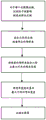
Fig. 6 shows an example workflow where the tilt measurement is performed before each full image scan.
Fig. 7 shows an example workflow in which tilt measurements are taken prior to acquiring each jet in an image scan.
FIG. 8 shows an example workflow in which a suitable region within the sample surface is identified and measured prior to each full scan image.
Fig. 9 shows an example workflow in which multiple suitable regions within a sample surface are identified and measured prior to each full scan image.
Fig. 10 shows how a dynamic focus tracking system can be used to predict a single focus position for scanning at a given position along the beam length.
Fig. 11 shows how differential focal values can be obtained using a dynamic focus tracking system for multiple positions along the full field of the spray.
Fig. 12 shows an example workflow where the differential focus can be measured from dynamic focus tracking data using a first spray to set a spray width for subsequent sprays of a full image scan.
Fig. 13 shows the example workflow of fig. 12 modified to allow jet width reduction if any single jet has too large a differential focus.
FIG. 14 shows the example workflow of FIG. 13 modified to allow for jet width increase if any single jet has a differential focus indicating that the jet width may have been larger.
Fig. 15 shows an example workflow in which focus merit values are calculated at positions on both sides and the middle of the jet to evaluate the tilt.
FIG. 16 shows the example workflow of FIG. 15 modified to additionally calculate average density values at both sides and the middle of the jet.
Detailed Description
Referring to fig. 1, there are a number of factors that can cause the sample height on the negative 7 to vary more rapidly than the focal depth of the image scanning device (typically in the 1 μm region) over the width of the jet taken by the image scanning device (typically in the 1mm region).
These factors include, but are not limited to:
1. temperature changes within the image scanning apparatus that tilt the side mounts or tilt the optics.
2. The backsheet itself has side-by-side wedges.
3. The film does not completely sit on the film base.
4. The sample (e.g., tissue section) is wedge-shaped.
5. There has been differential wear on the opposite sides of the backsheet chassis.
6. The arrangement of the system is not preferred.
These factors are shown in fig. 2, where the sources of error are exaggerated for clarity.
In general, the following discussion describes an example of our proposal to provide variable spray width in the context of operating an image scanning apparatus that includes a scan line detector.
This concept can be understood with reference to fig. 2, which shows the limit of the jet width where the sample surface on the plate remains within the depth of focus, referred to as the "maximum usable jet width". The maximum usable spray width may be defined as the maximum spray width in the focal point that can hold the sample surface at the spray width in the spray width direction.
If a region outside this maximum available spray width is used, the resulting image will be out of focus and not suitable for this purpose.
The inventors have observed that if the jet width is set to the maximum available jet width, rather than the maximum possible jet width, this will allow the entire sample to be scanned to be in focus. In particular, for image scanning devices with zero or low tilt, the sample on the negative can be scanned with the minimum number of jets using a jet with the largest possible jet width, which results in the shortest scan time. For image scanning devices with significant tilt, the negative can still be scanned without loss of image quality due to reduced beam width. For example, for an image scanning device with a 1 μm focal depth and a sample with a 2 μm slope in the jet width, the focused jet can still be acquired by reducing the jet width to be scanned to half the normal jet width. This will produce the same image quality as a scanner without tilt, but the scan time will increase due to the larger number of jets required for the same scan area.
To set the jet width to the maximum available jet width or the maximum possible jet width, the maximum available jet width should be determined first. To determine the maximum available spray width, a differential focus may be calculated. The differential focus may be defined to indicate a distance between: (i) a focused horizontal line at a first location on the sample surface; and (ii) a focused horizontal line at a second location on the sample surface; wherein the first position and the second position are offset from each other in said scan width direction 5. The first and second locations may correspond to locations on opposite sides (e.g., opposite ends) of a scan line or a group of scan lines.
The differential focus can be measured by "focus sweeping" at a single line location 7 on the sample. The focus sweep may be considered a 2D image in the xz plane rather than a 2D image in the xy plane. This can be achieved simply by moving the lens focus along the z-axis, for example by moving the lens 1 along the imaging axis 9 as the scan line detector 2 collects data, or by performing successive single line scans at different focus positions. From the scan lines acquired in the focal sweep (as an image or a superposition of images), the output value of the focus evaluation function can be calculated at two positions on either side of the line position 7 as a function of the focal position (z-axis). Peaks in the merit function indicate "focus" horizontal lines. Thus, the difference between the output values of the merit functions of the two positions on either side of the line position 7 provides a differential focus, which knows the distance between the focus horizontal lines of the two positions.
It can be said that the output value of the focus merit function provides a measure of focus quality, and there are many functions that can be used, which are typically based on the difference of neighboring pixels. An example of this is in fig. 3, where the output values of the focus merit function on each side of the jet have peaks at different focus positions (z-axis). The fact that the output value of the focus merit function has different peaks at two locations is not important and merely indicates that the measured sample has different detail levels at those two locations (i.e., over the width of the spray). It is the difference in focus position that provides the differential focus. For the example shown in fig. 3, the differential focus shown in fig. 3 in arbitrary units ("AU") is derived from the position of the imaging lens 1 along the imaging axis, but other measures of focus position may be used as well.
In the example of fig. 3, the output value of the focus evaluation function is calculated using neighboring pixels at positions (left edge, right edge) at either end of the line scan resulting from the focus scan.
If the differential focus is measured over the largest possible jet width, the largest available jet width can be determined as the smaller of the largest possible jet width or the depth of focus multiplied by the largest possible jet width and divided by the differential focus. This can be represented by:
the smaller of MU ═ α ═ dof Mp/Δ f) and Mp
Where MU is the maximum available beam width, dof is the depth of focus, Mp is the maximum possible beam width, Δ f is the difference focus, and α is a scaling factor that allows variability in tilt (typically this factor will be close to 1).
Multiple points across the width of the spray and corresponding straight or curved lines to the peaks may also be used. This can be seen in fig. 4 and 5.
In the example of fig. 4, the focus merit function is calculated using adjacent pixels on either side of the line scan (left edge, right edge) and also at an intermediate position between either end of the line scan and the center of the line scan (center left edge, center right edge).
If it is only necessary to compensate for variations or errors in the image scanning apparatus, rather than to compensate for the negative 7 or the sample itself, the known target can be used to determine the maximum available spray width, rather than being measured directly from the sample on the negative 7. Typically, the target will be a square wave grating mounted in a scanner from a mount for the negative, respectively, for example so that the target can be moved into and out of the imaging axis 9. Target types other than square wave gratings may be used. Also, targets that are not permanently mounted within the scanner, but rather in a mount for the negative, may be used. The same technique of measuring differential focus can be used on the target, as already described above. It is also not necessary to mount the target without any tilt, as the tilt level of the target relative to the mounted negative is known, and this tilt can be subtracted from the target measured tilt to get the true tilt of the mounted negative. In this way, we can either measure the inclination of the negative directly, or can measure the change in the inclination of the target to derive the inclination of the negative.
From knowledge of the depth of focus, it is then possible to define the maximum available spray width and set the spray width of the scanner to maintain image quality.
When it is preferred to set the jet width equal to the maximum available jet width, the jet width can instead be calculated with a buffer (buffer) slightly smaller than the maximum available jet width to ensure that the distance between the focal horizontal lines of the jet edges does not exceed the focal depth of the image scanning device. In either case, the jet width is set based on at least one measure (differential focus) that indicates that the sample surface on the negative is not flat (in this case tilted) in the scan width direction relative to the imaging plane of the image scanning device.
This measurement of the inclination of the mounted negative can be done periodically, typically every 30 minutes, if the scanner changes slowly. If the change in tilt is rapid, a tilt measurement may be performed before each full image scan, as is done in the workflow shown in FIG. 6. If the change is very fast, a tilt measurement may also be taken before each spray in the image scan is acquired. This sequence is shown in figure 7. If the tilt is measured before each jet, this can give an image with different jet widths within the full scan image.
If one wants to compensate for the sample, the negative and the negative base, one needs to scan the sample itself (i.e. the object used to measure the inclination must be the same as the object to be scanned). A suitable area within the sample surface (with details extending across the width of the spray) can be identified and measured before each full scan image. The maximum available spray width for the full scan image can then be set. This is shown in figure 8.
The thickness of the tissue sample may vary across the sample, and a single measurement may not give a reliable measurement. However, if measurements are taken at multiple points on the tissue sample, these measurements can be combined to give more reliable results. The combination method can be a simple average or median or maximum or more complex method designed to remove outlier results, e.g., taking an average of 80% of the closest results. Such combination methods are well known to those skilled in the art. This is shown in fig. 9.
Taking multiple measurements from the sample surface on each backsheet 7 can be time consuming and can reduce productivity.
However, it is known to perform a focus scan at a single point in a predetermined region of the sample prior to imaging the sample in order to create a single focus horizontal line at which to begin the scan (note that the known method only involves determining a single focus horizontal line, rather than calculating a differential focus). By using this conventional focus scan to additionally calculate a differential focus value, the trend of many scans or negatives will be predicted. For example, if the tilt of the image scanning device has shifted, which will show up as similar differential focus among all negatives, the tilt can be reliably measured and adjusted for jet width if many negatives are analyzed with the measurements over a predetermined period of time (e.g., by averaging). This requires only a single focal sweep across each negative or full sample image, as has been customary in practice, to create a single focal horizontal line at which to begin the sweep.
If the scanner has a dynamic focus tracking system such as those described in US2014/0071438 or WO2013/017855 or US7485834, the differential focus can be measured/predicted during the scan of the jet. In these documents, the entire spray width is used to predict a single focal position at which a scan can be made at a given position along the length of the spray, as shown in fig. 10.
These dynamic focus tracking techniques can be modified to calculate a focus merit function on either end of the scan line from the jet to determine the focus position, allowing differential focus values to be obtained for multiple positions along the full length of the jet, as shown in fig. 11. Multiple differential focus values obtained at multiple locations along the full length of the jet can be combined to produce a single differential focus value to set the maximum available jet width. The combination method can be a simple average or median or maximum or more complex method designed to remove outlier results, e.g., taking an average of 80% of the closest results. Such combination methods are well known to those skilled in the art.
This measurement of differential focus can use the first jet measurement from the dynamic focus tracking data to set the jet width for all thickness jets of the full image scan, as shown in fig. 12.
If a differential focus error is monitored from dynamic focus tracking data on subsequent jets, it can be analyzed whether any individual jet has too much differential focus. If so, the spray may be repeated, but with a reduced spray width, as shown in FIG. 13. Note that in this case, the spray needs to be repeated because the center of the spray scan must be moved in the x-direction to ensure that the spray width adjoins the previous adjacent spray. This means that different jets within the same full scan image will have different widths. At the end of the reduced width jet, the jet for the subsequent jet can be returned to the jet width calculated after the first jet or can be maintained at the reduced jet width.
If the differential focus data from the jet indicates that the jet width has been greater than the jet width used, additional jet image data on the side not adjoining the previously scanned jet may be used, as shown in fig. 14. Subsequent jets can then be scanned with a greater jet width.
Also, trends can be predicted by using focus tracking data for each spray for many scans or negatives. If the inclination of the scanner has shifted, this will show up as an error in many negative, and if many negative are analyzed with the measurements (e.g. averaged), the inclination can be reliably measured and the maximum available spray width adjusted accordingly.
The example workflows shown in fig. 11-14 use only two locations on either side of the spray to calculate the output value of the focus merit function, but more locations on the spray may be used to calculate the output value of the focus merit function and the predicted difference focus in the same manner as shown in fig. 5.
If no dynamic focus data is available, a metric indicating that the sample surface on the negative is not flat (e.g., tilted) in the scan width direction relative to the imaging plane of the image scanning device can still be estimated from the scanned spray image itself. This may be done using multiple scan lines from the jet (as shown below), or even using only a single scan line from the jet (not shown).
For example, the focus merit values (output values of the focus merit function) may be calculated at positions on both sides and in the middle of the spray, and if it is known that the details in the sample are uniform over the entire spray, the relative values of the edge merit values may be compared with the center merit value to evaluate whether the sample on the negative 7 is tilted, and thereby adjust the spray width.
In particular, if the detail in the sample is uniform, the two edge scores will match. If the sample is uniform and has no tilt, the two edge scores will match and the center score will match. If the sample is uniform and has a slope, the edge merit will match but be lower than the center merit. This is shown in figure 15. From all these decisions we can determine if the spray width is too wide as follows: whether there are excessive decisions in which it is determined that there is a gradient in the system. If desired, the jet width can be reduced and repeated.
The amount of spray width reduction may be determined from monitoring additional points on the spray width, such as three points of one-third, four points of one-fourth, eight points of one-eighth, or more. These cases may have the same logic as the application shown in fig. 15, and the widest set of points that meet the acceptance criteria for the number of "no" decisions may be used to set the maximum available spray width.
A further modification is shown in figure 16. Here, the average density value of each segment of the spray can be measured. If the features in the sample are uniform, the average density values of the individual segments of the spray will be similar. If the average density values of the segments of the spray are different, the fine portion will be uneven even if the evaluation values of the segments are the same. This provides a check to ensure that the scan lines are suitable for measuring tilt, because if the average density values are different, the scan lines are not available for assessing tilt. The required reduction in the jet width can be calculated in the same way as with more segments in the jet width using not only the focus merit value but also the average density matched to the other segments.
As in example workflows in which differential focus is used to change jet width, such as those shown in fig. 12-14, we can use focus evaluation data to adjust the jet width to the maximum available jet width.
Moreover, the maximum available spray width measurement determined according to the example workflow shown in fig. 15 and 16 may be used to predict trends. For example, if the maximum available spray width decreases over time, the user may be notified to have someone perform corrective action, such as visiting a maintenance person. The predicted trend may inform the user that corrective action will be required at certain intervals before the maximum available spray width is actually needed to reduce and impact scanner productivity.
Those skilled in the art will appreciate that various combinations of the example workflows set forth above can be used.
The terms "comprises" and "comprising," "including," and variations thereof, as used in the specification and claims of this application, are intended to cover a particular feature, step, or integer. The terms are not to be taken as excluding the possibility of other features, steps or integers being present.
The features disclosed in the foregoing description, or the following claims, or the accompanying drawings, expressed in their specific forms or in terms of a means for performing the disclosed function, or a method or process for attaining the disclosed result, as appropriate, may, separately, or in any combination of such features, be utilised for realising the application in diverse forms thereof.
While the present application has been described in terms of the above exemplary embodiments, many equivalent modifications and variations will be apparent to those skilled in the art when given this application. Accordingly, the exemplary embodiments of the present application, as set forth above, are considered to be illustrative and not restrictive. Various changes to the described embodiments may be made without departing from the spirit and scope of the application.
For the avoidance of any doubt, any theoretical explanation provided for in this application is given in order to facilitate the reader's understanding. The inventors do not wish to be bound by any of these theoretical explanations.
All references mentioned above are incorporated by reference into this application.
The following descriptions provide general representations of the disclosure of the present application:
A. when the jet width must be reduced to maintain image quality
B. The focus position is measured at two locations on the spray beam to determine the differential focus of the focus sweep or focus overlay.
C. The focus position is measured by combining multiple position data at more than two locations on the spray in a focus sweep or focus stack to determine a differential focus.
D. The differential focus is measured from the internal target, and the jet width is set to the maximum available jet width.
E. The differential focus is measured from an external target, and the spray width is set to the maximum available spray width.
F. The differential focus is measured from a suitable area of the sample and the jet width is set to the maximum available jet width.
G. The differential focus is measured from a suitable area of the sample before each full image scan, and the spray width is set to the maximum available spray width.
H. Differential focus was measured from multiple suitable regions of the sample prior to each full image scan, and the jet width was set to the maximum available jet width.
I. The differential focus of the sample is measured from dynamic focus tracking data of the first jet at a plurality of points along the jet, and the jet width of the full image scan is set to the maximum available jet width of the first jet.
J. The differential focus of the sample is measured from dynamic focus tracking data of the first jet at a plurality of points along the jet, and the jet width of the full image scan is set to the maximum available jet width of the first jet. Subsequent jets are also measured and if the maximum available jet width is smaller, the jet with the smaller jet width is repeated.
K. The differential focus of the sample is measured from dynamic focus tracking data of the first jet at a plurality of points along the jet, and the jet width of the full image scan is set to the maximum available jet width of the first jet. Subsequent jets are also measured and if the maximum available jet width is smaller, the jet with the smaller jet width is repeated. If the maximum available jet width is greater than the used jet width, additional jet image data on the side of the jet that does not adjoin any previous jets is saved.
L. measuring the focus evaluation values of the scanned spray image at the edge and center of the spray. When the edge evaluation values match to be within the tolerance and the center evaluation values match to be within the tolerance, the spray is accepted. When the edge evaluation value matches and the center evaluation value improves, the spray width is reduced.
M. the amount of jet width reduction in step L can be calculated from measuring the focus merit values at multiple locations on the jet and using the maximum jet width, where the center and side values all match to within tolerance.
N. use steps L and M and set the spray width of the full image scan to the maximum available spray width of the first spray.
O. use steps L and M and set the spray width of the full image scan to the maximum available spray width of the first spray. Subsequent jets are also measured and if the maximum available jet width is smaller, the jet with the smaller jet width is repeated.
P. use steps L and M and set the spray width of the full image scan to the maximum available spray width of the first spray. Subsequent jets are also measured and if the maximum available jet width is smaller, the jet with the smaller jet width is repeated. If the maximum available jet width is greater than the used jet width, additional jet image data on the side of the jet that does not adjoin any previous jets is saved.
Measuring the focus evaluation value of the scanned spray image and the density at the edge and center of the spray. When the edge evaluation value and the density value are matched to be within the tolerance and the center evaluation value and the density value are matched to be within the tolerance, the blast is accepted. When all density values match to be within tolerance, the edge evaluation values match, and the center evaluation value improves, the spray width is reduced.
R. the jet width reduction in step Q can be calculated from measuring the focus merit values at multiple locations on the jet and using the maximum jet width, where the center and side values all match to within tolerance.
S. use steps Q and R and set the spray width of the full image scan to the maximum available spray width of the first spray.
T. use steps Q and R and set the spray width of the full image scan to the maximum available spray width of the first spray. Subsequent jets are also measured and if the maximum available jet width is smaller, the jet with the smaller jet width is repeated.
U. use steps Q and R and set the spray width of the full image scan to the maximum available spray width of the first spray. Subsequent jets are also measured and if the maximum available jet width is smaller, the jet with the smaller jet width is repeated. If the maximum available jet width is greater than the used jet width, additional jet image data on the side of the jet that does not adjoin any previous jets is saved.
Claims (16)
1. A method of operating an image scanning device,
wherein the image scanning apparatus comprises a scan line detector and is configured to image a surface of an object mounted in the image scanning apparatus with a plurality of jets, wherein each jet is formed by a set of scan lines, each scan line being acquired using the scan line detector from a respective elongated region of the surface of the object extending in a scan width direction, and wherein each set of scan lines is acquired while moving the object in a scan length direction relative to the scan line detector;
the method comprises the following steps:
acquiring a plurality of scan lines from a surface of a first object mounted in the image scanning apparatus using the scan line detector, wherein each scan line of the plurality of scan lines is acquired at a particular focus setting;
generating an image based on the plurality of scan lines;
identifying a first focus level line from a first portion of the image representing a first end of one of the plurality of scan lines and a second focus level line from a second portion of the image representing a second end of the one of the plurality of scan lines;
obtaining at least one measure indicative of a surface of a first object being uneven in the scan width direction relative to an imaging plane of the image scanning device, wherein the at least one measure is a differential focus defined by a distance between the first focus level and the second focus level;
setting a spray width value for acquiring at least one spray from a surface of a second object mounted in the image scanning apparatus, wherein the spray width value is set based on the at least one measurement and is configured to keep each spray acquired from the surface of the second object substantially in focus on a width of the second object in the scan width direction; and
acquiring at least one jet from the surface of the second object using the scan line detector, wherein a width of the at least one jet acquired from the surface of the second object in the scan width direction corresponds to the jet width value set based on the at least one measure.
2. The method of claim 1, wherein the second object is the same as the first object.
3. The method of claim 1, wherein the second object is different from the first object.
4. The method of claim 1, wherein a first end of the scan line and a second end of the scan line are offset from each other in the scan width direction.
5. The method according to claim 4, wherein the differential focus is calculated using output values of a focus merit function calculated at the first end and the second end located offset from each other in the scan width direction.
6. The method of claim 4, wherein the at least one metric comprises a plurality of differential foci combined to provide a combined differential focus, wherein the jet width value is based on the combined differential focus setting.
7. The method of claim 1, wherein the second object is the same object as the first object, and the method comprises identifying one or more regions on the object surface suitable for acquiring the plurality of scan lines, and then acquiring the plurality of scan lines from the one or more identified regions on the object surface.
8. The method of claim 1, wherein the plurality of scan lines are taken from a single elongated region of the first object surface extending in the scan width direction.
9. The method of any of claims 1-8, wherein the plurality of scan lines are acquired from respective elongated regions of the surface of the first object extending in the scan width direction while the first object is moved relative to the scan line detector in the scan length direction.
10. The method of claim 1, wherein the second object is the same object as the first object, wherein the plurality of scan lines is a set of scan lines that form a jet, the jet acquired from a surface of the object using a dynamic focus tracking method in which focus settings of the image scanning device are adjusted while the jet is acquired.
11. The method of claim 10, wherein scan lines forming a new spray are used to obtain the at least one measurement each time a new spray is acquired from the surface of the object, wherein the spray width value is set based on the at least one measurement such that the spray width value is set each time a new spray is acquired.
12. The method of claim 11, wherein if a jet width value based on a new jet setting obtained from the surface of the object is less than a previously set jet width value used in the new jet acquisition process, then decreasing a width of the new jet based on a smaller jet width value that has been based on the new jet setting, wherein if a jet width value based on a new jet setting obtained from the surface of the object is greater than a previously set jet width value used in the new jet acquisition process, then increasing a width of the new jet based on a larger jet width value that has been based on the new jet setting.
13. The method of claim 1, wherein the jet width value is set based on the at least one measure and a depth of focus of the image scanning device, wherein the at least one measure and the depth of focus are used to set a jet width value that is considered to maximize a maximum available jet width of the acquired jet widths while substantially maintaining focus of each jet acquired from a surface of the second object over a width of the second object in the scan width direction.
14. The method of any one of claims 1-13, wherein the second object is a backsheet having a sample thereon, wherein the sample is a biological specimen.
15. An image scanning device comprising a scan line detector,
wherein the image scanning apparatus is configured to image a surface of an object mounted in the image scanning apparatus with a plurality of jets, wherein each jet is formed by a set of scan lines, each scan line being acquired using the scan line detector from a respective elongated region of the surface of the object extending in a scan width direction, wherein each set of scan lines is acquired while moving the object in a scan length direction relative to the scan line detector;
wherein the image scanning device is further configured to:
acquiring a plurality of scan lines acquired from a surface of a first object mounted in the image scanning apparatus using the scan line detector, wherein each scan line of the plurality of scan lines is acquired at a particular focus setting;
generating an image based on the plurality of scan lines;
identifying a first focus level line from a first portion of the image representing a first end of one of the plurality of scan lines and a second focus level line from a second portion of the image representing a second end of the one of the plurality of scan lines;
obtaining at least one measure indicative of a surface of a first object being uneven in the scan width direction relative to an imaging plane of the image scanning device, wherein the at least one measure is a differential focus defined by a distance between the first focus level and the second focus level;
setting a spray width value for acquiring at least one spray from a surface of a second object mounted in the image scanning apparatus, wherein the spray width value is set based on the at least one measurement and is configured to keep each spray acquired from the surface of the second object substantially in focus on a width of the second object in the scan width direction;
acquiring at least one jet from the surface of the second object using the scan line detector, wherein a width of the at least one jet acquired from the surface of the second object in the scan width direction corresponds to the jet width value set based on the at least one measure.
16. A non-transitory computer-readable medium having computer-executable instructions configured to cause an image scanning apparatus to implement the method of any one of claims 1-14.
Applications Claiming Priority (3)
| Application Number | Priority Date | Filing Date | Title |
|---|---|---|---|
| US201562265015P | 2015-12-09 | 2015-12-09 | |
| US62/265,015 | 2015-12-09 | ||
| PCT/EP2016/080360 WO2017097950A1 (en) | 2015-12-09 | 2016-12-09 | An image scanning apparatus and methods of operating an image scanning apparatus |
Publications (2)
| Publication Number | Publication Date |
|---|---|
| CN108369337A CN108369337A (en) | 2018-08-03 |
| CN108369337B true CN108369337B (en) | 2021-03-30 |
Family
ID=57708545
Family Applications (1)
| Application Number | Title | Priority Date | Filing Date |
|---|---|---|---|
| CN201680072104.0A Active CN108369337B (en) | 2015-12-09 | 2016-12-09 | Image scanning apparatus and method of operating the same |
Country Status (7)
| Country | Link |
|---|---|
| US (1) | US10462322B2 (en) |
| EP (1) | EP3387480B1 (en) |
| JP (1) | JP6901484B2 (en) |
| CN (1) | CN108369337B (en) |
| AU (1) | AU2016367209B2 (en) |
| CA (1) | CA3002319C (en) |
| WO (1) | WO2017097950A1 (en) |
Families Citing this family (5)
| Publication number | Priority date | Publication date | Assignee | Title |
|---|---|---|---|---|
| KR102523559B1 (en) * | 2017-09-29 | 2023-04-19 | 라이카 바이오시스템즈 이미징 인크. | A digital scanning apparatus |
| WO2019170564A1 (en) | 2018-03-06 | 2019-09-12 | Ventana Medical Systems, Inc. | Digital pathology scanning interface and workflow |
| CN110852999B (en) * | 2019-10-29 | 2023-03-10 | 北京临近空间飞行器系统工程研究所 | Image scanning system and image scanning method |
| TWI817063B (en) * | 2019-11-25 | 2023-10-01 | 美商好樂杰公司 | Digital imaging system and method |
| CN113596276B (en) * | 2021-06-28 | 2022-09-27 | 展讯半导体(南京)有限公司 | Scanning method and system for portable electronic equipment, electronic equipment and storage medium |
Family Cites Families (10)
| Publication number | Priority date | Publication date | Assignee | Title |
|---|---|---|---|---|
| JP3460131B2 (en) * | 1995-06-29 | 2003-10-27 | 株式会社ニコン | Projection exposure equipment |
| JP2004361431A (en) * | 2003-05-30 | 2004-12-24 | Minolta Co Ltd | Imaging unit |
| GB0414201D0 (en) * | 2004-06-24 | 2004-07-28 | Fujifilm Electronic Imaging | Method and apparatus for forming a multiple focus stack image |
| GB0503032D0 (en) * | 2005-02-14 | 2005-03-23 | Fujifilm Electronic Imaging | Blip focus |
| EP2720076B1 (en) * | 2009-12-30 | 2019-04-03 | Koninklijke Philips N.V. | Self autofocus sensor |
| GB201113071D0 (en) * | 2011-07-29 | 2011-09-14 | Ffei Ltd | Method and apparatus for image scanning |
| WO2013040686A1 (en) * | 2011-09-21 | 2013-03-28 | Huron Technologies International Inc. | Slide scanner with a tilted image plane |
| JP2013083925A (en) * | 2011-09-29 | 2013-05-09 | Canon Inc | Imaging apparatus and control method therefor |
| CA2868263C (en) * | 2012-03-23 | 2021-04-13 | Huron Technologies International Inc. | Slide scanner with dynamic focus and specimen tilt and method of operation |
| GB2505691B (en) | 2012-09-07 | 2018-02-21 | Ffei Ltd | Method and apparatus for image scanning |
-
2016
- 2016-12-09 WO PCT/EP2016/080360 patent/WO2017097950A1/en active Application Filing
- 2016-12-09 CN CN201680072104.0A patent/CN108369337B/en active Active
- 2016-12-09 JP JP2018529947A patent/JP6901484B2/en active Active
- 2016-12-09 AU AU2016367209A patent/AU2016367209B2/en active Active
- 2016-12-09 EP EP16820178.8A patent/EP3387480B1/en active Active
- 2016-12-09 CA CA3002319A patent/CA3002319C/en active Active
-
2018
- 2018-06-08 US US16/004,237 patent/US10462322B2/en active Active
Also Published As
| Publication number | Publication date |
|---|---|
| CA3002319A1 (en) | 2017-06-15 |
| AU2016367209A1 (en) | 2018-04-26 |
| EP3387480B1 (en) | 2020-01-15 |
| JP6901484B2 (en) | 2021-07-14 |
| US10462322B2 (en) | 2019-10-29 |
| US20180295254A1 (en) | 2018-10-11 |
| JP2018538574A (en) | 2018-12-27 |
| EP3387480A1 (en) | 2018-10-17 |
| AU2016367209B2 (en) | 2021-06-17 |
| CA3002319C (en) | 2022-06-14 |
| CN108369337A (en) | 2018-08-03 |
| WO2017097950A1 (en) | 2017-06-15 |
Similar Documents
| Publication | Publication Date | Title |
|---|---|---|
| CN108369337B (en) | Image scanning apparatus and method of operating the same | |
| JP5718329B2 (en) | Microscopy with adaptive optics | |
| KR101257188B1 (en) | Three-dimensional shape measuring device, three-dimensional shape measuring method, and computer readable recording medium for three-dimessional shape measuring program | |
| CN107238919B (en) | Method and apparatus for image scanning | |
| US20050258335A1 (en) | Microscope system | |
| JP2018515782A5 (en) | ||
| CN108885089B (en) | Focusing system for telecentric optical measuring machine | |
| CN103698879B (en) | A kind of device and method of real-time focusing | |
| JP2006268835A (en) | Method and device for predicting focus position | |
| JP2011007576A (en) | Measurement system and measurement processing method | |
| AU2018352821B2 (en) | Image reconstruction method, device and microscopic imaging device | |
| CN1550914A (en) | Assembly comprising a sensor, a method therefor and a lithographic projection apparatus | |
| EP2884326B1 (en) | Method and apparatus for estimating an in-focus position | |
| US20140184780A1 (en) | Apparatus and control method therefor | |
| JP2013113696A (en) | Displacement measuring method and displacement measuring apparatus | |
| JP2011099821A (en) | Method and device for measuring optical shape of plate material | |
| JP2011158784A (en) | Measuring apparatus and measuring method therefor | |
| CN104880913A (en) | Focusing-leveling system for increasing process adaptability | |
| JP2012026998A (en) | Focal point three-dimensional coordinate measurement method and device using discrete divergent pencil-of-rays group | |
| JP5068473B2 (en) | Edge straightness measurement method and program | |
| JP6800529B2 (en) | Measurement method and measurement program | |
| CN113358056B (en) | Scanning method, scanning system and storage medium for workpiece surface morphology | |
| KR0129054B1 (en) | Measuring method and apparatus for plate transformation of steel plate | |
| WO2022074926A1 (en) | Test chart, camera manufacturing device, camera manufacturing method, and focus detection program | |
| KR20230149932A (en) | Apparatus and method for measuring a focal length |
Legal Events
| Date | Code | Title | Description |
|---|---|---|---|
| PB01 | Publication | ||
| PB01 | Publication | ||
| SE01 | Entry into force of request for substantive examination | ||
| SE01 | Entry into force of request for substantive examination | ||
| GR01 | Patent grant | ||
| GR01 | Patent grant |