JP5718329B2 - Microscopy with adaptive optics - Google Patents
Microscopy with adaptive optics Download PDFInfo
- Publication number
- JP5718329B2 JP5718329B2 JP2012519780A JP2012519780A JP5718329B2 JP 5718329 B2 JP5718329 B2 JP 5718329B2 JP 2012519780 A JP2012519780 A JP 2012519780A JP 2012519780 A JP2012519780 A JP 2012519780A JP 5718329 B2 JP5718329 B2 JP 5718329B2
- Authority
- JP
- Japan
- Prior art keywords
- beamlet
- beamlets
- light
- sample
- modulation element
- Prior art date
- Legal status (The legal status is an assumption and is not a legal conclusion. Google has not performed a legal analysis and makes no representation as to the accuracy of the status listed.)
- Active
Links
- 230000003044 adaptive effect Effects 0.000 title description 34
- 238000000386 microscopy Methods 0.000 title description 25
- 230000005284 excitation Effects 0.000 claims description 91
- 230000004075 alteration Effects 0.000 claims description 66
- 238000000034 method Methods 0.000 claims description 50
- 238000012937 correction Methods 0.000 claims description 37
- 230000005855 radiation Effects 0.000 claims description 23
- 238000003384 imaging method Methods 0.000 claims description 20
- 230000001678 irradiating effect Effects 0.000 claims description 15
- 239000011324 bead Substances 0.000 claims description 11
- 230000001939 inductive effect Effects 0.000 claims description 4
- 239000000523 sample Substances 0.000 description 118
- 210000001747 pupil Anatomy 0.000 description 53
- 230000003287 optical effect Effects 0.000 description 22
- 238000010586 diagram Methods 0.000 description 20
- 238000013459 approach Methods 0.000 description 17
- 238000005259 measurement Methods 0.000 description 17
- 230000008569 process Effects 0.000 description 13
- 238000004590 computer program Methods 0.000 description 8
- 230000006870 function Effects 0.000 description 7
- 238000005516 engineering process Methods 0.000 description 5
- 206010036618 Premenstrual syndrome Diseases 0.000 description 4
- 230000011218 segmentation Effects 0.000 description 4
- 230000001594 aberrant effect Effects 0.000 description 3
- 239000012472 biological sample Substances 0.000 description 3
- 239000003638 chemical reducing agent Substances 0.000 description 3
- 238000007654 immersion Methods 0.000 description 3
- 230000006872 improvement Effects 0.000 description 3
- 239000004973 liquid crystal related substance Substances 0.000 description 3
- 230000008901 benefit Effects 0.000 description 2
- 230000015572 biosynthetic process Effects 0.000 description 2
- 238000013461 design Methods 0.000 description 2
- 238000011161 development Methods 0.000 description 2
- 230000018109 developmental process Effects 0.000 description 2
- 230000000694 effects Effects 0.000 description 2
- 230000005684 electric field Effects 0.000 description 2
- 238000005286 illumination Methods 0.000 description 2
- 230000001965 increasing effect Effects 0.000 description 2
- 238000012986 modification Methods 0.000 description 2
- 230000004048 modification Effects 0.000 description 2
- 238000000399 optical microscopy Methods 0.000 description 2
- 230000010363 phase shift Effects 0.000 description 2
- 230000001443 photoexcitation Effects 0.000 description 2
- 230000009467 reduction Effects 0.000 description 2
- 238000011160 research Methods 0.000 description 2
- 238000000482 two photon fluorescence microscopy Methods 0.000 description 2
- XLYOFNOQVPJJNP-UHFFFAOYSA-N water Substances O XLYOFNOQVPJJNP-UHFFFAOYSA-N 0.000 description 2
- 241000122205 Chamaeleonidae Species 0.000 description 1
- 206010010071 Coma Diseases 0.000 description 1
- RTAQQCXQSZGOHL-UHFFFAOYSA-N Titanium Chemical compound [Ti] RTAQQCXQSZGOHL-UHFFFAOYSA-N 0.000 description 1
- 201000009310 astigmatism Diseases 0.000 description 1
- 238000005452 bending Methods 0.000 description 1
- 239000000969 carrier Substances 0.000 description 1
- 230000008859 change Effects 0.000 description 1
- 239000003795 chemical substances by application Substances 0.000 description 1
- 230000001427 coherent effect Effects 0.000 description 1
- 238000004891 communication Methods 0.000 description 1
- 239000012141 concentrate Substances 0.000 description 1
- 230000021615 conjugation Effects 0.000 description 1
- 238000010276 construction Methods 0.000 description 1
- 210000004748 cultured cell Anatomy 0.000 description 1
- 230000001419 dependent effect Effects 0.000 description 1
- 238000001514 detection method Methods 0.000 description 1
- 238000006073 displacement reaction Methods 0.000 description 1
- 238000002474 experimental method Methods 0.000 description 1
- 239000011521 glass Substances 0.000 description 1
- 238000011503 in vivo imaging Methods 0.000 description 1
- 230000010354 integration Effects 0.000 description 1
- 238000011835 investigation Methods 0.000 description 1
- 239000011159 matrix material Substances 0.000 description 1
- 230000007246 mechanism Effects 0.000 description 1
- 230000008450 motivation Effects 0.000 description 1
- 230000007935 neutral effect Effects 0.000 description 1
- 238000005457 optimization Methods 0.000 description 1
- 238000012545 processing Methods 0.000 description 1
- 230000000644 propagated effect Effects 0.000 description 1
- 238000004621 scanning probe microscopy Methods 0.000 description 1
- 239000004065 semiconductor Substances 0.000 description 1
- 230000001953 sensory effect Effects 0.000 description 1
- 230000000087 stabilizing effect Effects 0.000 description 1
- 229910052719 titanium Inorganic materials 0.000 description 1
- 239000010936 titanium Substances 0.000 description 1
- 238000012546 transfer Methods 0.000 description 1
- 230000000007 visual effect Effects 0.000 description 1
Images


Classifications
-
- G—PHYSICS
- G02—OPTICS
- G02B—OPTICAL ELEMENTS, SYSTEMS OR APPARATUS
- G02B26/00—Optical devices or arrangements for the control of light using movable or deformable optical elements
- G02B26/06—Optical devices or arrangements for the control of light using movable or deformable optical elements for controlling the phase of light
-
- G—PHYSICS
- G01—MEASURING; TESTING
- G01J—MEASUREMENT OF INTENSITY, VELOCITY, SPECTRAL CONTENT, POLARISATION, PHASE OR PULSE CHARACTERISTICS OF INFRARED, VISIBLE OR ULTRAVIOLET LIGHT; COLORIMETRY; RADIATION PYROMETRY
- G01J9/00—Measuring optical phase difference; Determining degree of coherence; Measuring optical wavelength
-
- G—PHYSICS
- G02—OPTICS
- G02B—OPTICAL ELEMENTS, SYSTEMS OR APPARATUS
- G02B21/00—Microscopes
- G02B21/36—Microscopes arranged for photographic purposes or projection purposes or digital imaging or video purposes including associated control and data processing arrangements
- G02B21/361—Optical details, e.g. image relay to the camera or image sensor
Landscapes
- Physics & Mathematics (AREA)
- General Physics & Mathematics (AREA)
- Spectroscopy & Molecular Physics (AREA)
- Optics & Photonics (AREA)
- Engineering & Computer Science (AREA)
- Multimedia (AREA)
- Chemical & Material Sciences (AREA)
- Analytical Chemistry (AREA)
- Microscoopes, Condenser (AREA)
- Investigating, Analyzing Materials By Fluorescence Or Luminescence (AREA)
- Investigating Or Analysing Materials By Optical Means (AREA)
Description
(関連出願の相互参照)
本出願は、2009年7月9日に出願された「Adaptive Optics Using Pupil Segmentation」と題する米国仮特許出願第61/224,102号明細書、2009年10月1日に出願された「Adaptive Optics Using Pupil Segmentation」と題する米国仮特許出願第61/247,929号明細書、2009年11月23日に出願された「Adaptive Optics Using Pupil Segmentation」と題する米国仮特許出願第61/263,614号明細書、及び、2009年11月30日に出願された「Adaptive Optics in Widefield Microscopy」と題する米国仮特許出願第61/265,225号明細書との優先権を主張する。これらの先に出願された出願の各々の主題は参照によって本明細書に組み込まれる。
(Cross-reference of related applications)
This application is based on US Provisional Patent Application No. 61 / 224,102 entitled “Adaptive Optics Using Pupil Segmentation” filed on July 9, 2009, “Adaptive Optics” filed on October 1, 2009. US Provisional Patent Application No. 61 / 247,929 entitled “Using Pupil Segmentation”; US Provisional Patent Application No. 61 / 263,614 entitled “Adaptive Optics Using Pupil Segmentation” filed on November 23, 2009; And US Provisional Patent Application No. 61 / 265,225 entitled “Adaptive Optics in Widefield Microscopy” filed Nov. 30, 2009. Claim priority with the specification. The subject matter of each of these previously filed applications is incorporated herein by reference.
本開示は、顕微鏡検査法に関し、特に、適応光学系を有する顕微鏡検査法に関する。 The present disclosure relates to microscopy, and in particular, to microscopy with adaptive optics.
光学顕微鏡法は、数世紀前の発明以来、注目すべきコントラスト機構およびハードウェアの実現とともに多くの段階を通じて進化してきた。しかしながら、その使用に関する基本的な動機、すなわち、裸眼で識別できない造りを解像することができることは変わっていない。結果として、より高い分解能への動きが近年における光学顕微鏡開発の焦点になっており、従来の光学顕微鏡法の回折限界を打ち破るためにいくつかの方法が示されている。こうした努力にもかかわらず、多くの場合に正当に評価されない1つの事実が残っており、すなわち、多くの生物サンプルでは、高性能な研究用顕微鏡の場合でさえも回折限界の分解能が実現されることは稀である。光学顕微鏡の理想的な画像性能では、設定された浸漬媒体の光学特性と同じ光学特性を有するサンプルに励起光および放射光の両方あるいはどちらか一方を通す必要があり、このような条件からのずれがあると、収差として知られる光学的歪みが生じて、信号、画像忠実度、および分解能の損失をもたらす。実際に、生物サンプルは、不均質な光学特性を有しており、したがって、画像は生物組織内の深さが増すにつれて次第に画質が低下する。 Optical microscopy has evolved through many stages with the realization of remarkable contrast mechanisms and hardware since the invention centuries ago. However, the basic motivation for its use, that is, the ability to resolve structures that cannot be identified with the naked eye, has not changed. As a result, the move to higher resolution has become the focus of optical microscope development in recent years, and several methods have been presented to overcome the diffraction limits of conventional optical microscopy. Despite these efforts, one fact remains that is often not justified, i.e., many biological samples achieve diffraction-limited resolution even with high-performance research microscopes. That is rare. The ideal image performance of an optical microscope requires that excitation and / or radiant light be passed through a sample that has the same optical properties as the immersion media that has been set. Presents an optical distortion known as aberration, resulting in loss of signal, image fidelity, and resolution. In fact, biological samples have inhomogeneous optical properties, and therefore the image gradually degrades in image quality as the depth in the biological tissue increases.
天文学で使用される光学望遠鏡の場合にも同様の課題が存在する。遠方の星からとらえられる光は、まず地球の擾乱大気を横断しなければならず、擾乱大気が光学的歪みを与えて画像品質を著しく低下させる。適応光学系(「AO」)と総称される、このような歪みを積極的に補正する方法によって、地上望遠鏡では地球外物体の回折限界画像が得られるようになった。天文学における適応光学系は概念的に簡単であり、すなわち結像面の近くに配置されるセンサーが歪んだ波面を直接測定し、可変鏡などの能動光学素子がこの波面をフィードバックループで修正して回折限界性能を回復させる。しかしながら、顕微鏡検査法における適応光学系は、収差のある波面を直接的に測定することが困難であるためにさほど容易でなく、結局のところ、試料内に波面センサーを配置することができることは稀である。試料からの後方散乱光はこのような直接波面センシングに使用されてきたが、このような方法は、結像面に対する収差と結像面からの収差のいずれをも激しく変化させる可能性があり、多重散乱光によってさらに複雑化する。 Similar challenges exist for optical telescopes used in astronomy. Light captured from distant stars must first traverse the Earth's turbulent atmosphere, which distorts the image and significantly degrades image quality. The method of actively correcting such distortion, collectively referred to as adaptive optics (“AO”), has enabled terrestrial telescopes to obtain diffraction-limited images of extraterrestrial objects. Adaptive optics in astronomy is conceptually simple: a sensor placed near the imaging plane directly measures the distorted wavefront, and an active optical element such as a deformable mirror corrects this wavefront with a feedback loop. Restore diffraction limited performance. However, the adaptive optical system in microscopy is not so easy because it is difficult to directly measure the wavefront with aberration, and after all, it is rare that a wavefront sensor can be placed in the sample. It is. Backscattered light from the sample has been used for such direct wavefront sensing, but such a method can drastically change both the aberration with respect to the imaging surface and the aberration from the imaging surface, Further complicated by multiple scattered light.
本開示では、光学系の後瞳がセグメント化され、セグメントが波面変調デバイスによって個々に制御され、光学系内の励起ビームまたは放射ビームの個々のビームレットの方向および位相を制御し、サンプルおよびシステムによって誘発される収差に対する適応光学系補正を行う顕微鏡検査技術を説明する。 In this disclosure, the back pupil of the optical system is segmented, the segments are individually controlled by the wavefront modulation device, and the direction and phase of the individual beamlets of the excitation beam or radiation beam in the optical system are controlled. A microscopy technique for performing adaptive optics correction for aberrations induced by the.
一般的な態様では、サンプルの画像を形成する方法は、サンプル内の焦点にビームの断面が個々のビームレットを含む、光源からの励起光のビームを収束させるステップと、焦点をサンプル内の複数の異なる位置まで走査するステップとを含む。個々のビームレットの角度は焦点が複数の異なる位置にあるときに独立に制御されて焦点における励起光の収差を低減させる。個々のビームレットの角度を独立に制御するステップは、他のビームレットがオフの間に個々のビームレットをオンにし、サンプルを画像化して記ビームレットに対する角度を決定するステップと、個々のビームレットに対応する個々の小区域を含む波面変調素子で前記励起ビームを変調するステップと、個々の小区域内で、対応する個々のビームレットの位相に空間的勾配を誘導するために対応するビームレットに小区域によって与えられる位相値のプロファイルを制御するステップと、を含む。さらに、この方法は、焦点が複数の異なる位置にあるときに、焦点において個々のビームレットが互いに建設的に干渉するように、個々のビームレットの相対位相を独立に制御するステップと、焦点が複数の異なる位置にあるときに焦点から放射された放射光を検出するステップと、焦点の複数の異なる位置から検出された放射光に基づいてサンプルの画像を作成するステップと、を含む。
実施形態は、以下の特徴の1つまたは複数を含むことができる。例えば、複数の異なる位置はサンプルの平面内に位置してもよく、平面はサンプル内の励起ビームの軸に対して垂直または非垂直であってよい。励起光は第1の波長を有していてもよく、放射光は第1の波長よりも小さい(例えば、第1の波長のおよそ半分の)第2の波長を有する。波面変調素子は、空間光変調器を含んでいてもよく、空間光変調器の活性層から反射される光にグローバルな位相ランプを適用して、空間光変調器の前面から反射される光と活性層から反射される光との間に非ゼロ角度を誘導するステップをさらに含むことができる。
In a general aspect, a method of forming an image of a sample comprises : converging a beam of excitation light from a light source, wherein the beam cross-section includes individual beamlets at a focal point in the sample; Scanning to different positions. Angle of the individual beamlets that are controlled independently by reducing the aberrations of the excitation light at the focus when the focus is in a plurality of different positions. Independently controlling the angle of each beamlet includes turning on each beamlet while the other beamlets are off, imaging the sample to determine the angle relative to the beamlet, Modulating the excitation beam with a wavefront modulation element including individual subregions corresponding to the let; and corresponding beamlets to induce a spatial gradient in the phase of the corresponding individual beamlet within the individual subregion Controlling the profile of the phase value provided by the subregion. Further, the method includes independently controlling the relative phase of the individual beamlets so that the individual beamlets constructively interfere with each other at the focal point when the focal point is at a plurality of different positions; Detecting emitted light emitted from the focal point when in a plurality of different positions and creating an image of the sample based on the emitted light detected from the different positions of the focal point.
Embodiments can include one or more of the following features. For example, the plurality of different positions may be located in the plane of the sample, and the plane may be perpendicular or non-perpendicular to the axis of the excitation beam in the sample. The excitation light may have a first wavelength and the emitted light has a second wavelength that is smaller than the first wavelength (eg, approximately half of the first wavelength). The wavefront modulation element may include a spatial light modulator, applying a global phase lamp to the light reflected from the active layer of the spatial light modulator, and the light reflected from the front surface of the spatial light modulator. The method may further include inducing a non-zero angle between the light reflected from the active layer.
位相値のプロファイルが決定されうる。一実施形態では、位相値を決定するステップは、励起ビームの複数の異なる個々のビームレットをサンプル内の参照物体に照射するステップを含んでいてもよく、複数の異なる個々のビームレットが波面変調素子の種々の対応する小区域によって変調される。参照物体からの放射光は参照物体に複数の異なる個々のビームレットが照射されるときに検出されてもよく、サンプル内の参照物体の位置は参照物体に複数の異なるビームレットが照射されるときに検出される放射光に基づいて決定されてもよい。決定された位置に基づいて、対応するビームレットの位相に空間的勾配を誘導するために、ビームレットが位相に空間的勾配を含むときに位置が互いに実質的に等しくなるように、小区域の対応するビームレットに各小区域によって与えられる位相値のビームレット−角度−補正プロファイルについての決定がなされうる。別の実施形態では、位相値を決定するステップは、複数のビームレットにおいて、波面変調素子の小区域に対応する各ビームレットに対して(a)ビームレットをサンプル内の参照物体に照射し、複数のビームレットの他のビームレットで参照物体を照射しないステップと、(b)参照物体にビームレットが照射されるときで参照物体が複数のビームレットの他のビームレットで照射されないときにサンプル内の参照物体から放射光を検出するステップと、(c)検出された放射光に基づいてサンプル内の参照物体の位置を決定するステップとを含むことができる。この後、決定された位置に基づいて、ビームレットが位相に空間的勾配を含むとき、ビームレットが位相に空間的勾配を含まないときに形成される焦点よりも小さいサイズを有するサンプル内の焦点で交差するように、対応するビームレットの位相に空間的勾配を誘導するために、小区域の対応するビームレットに各小区域によって与えられる位相値のビームレット−角度−補正プロファイルについての決定がなされうる。参照物体は蛍光ビーズであってもよい。 A phase value profile may be determined. In one embodiment, determining the phase value may include irradiating a plurality of different individual beamlets of the excitation beam to a reference object in the sample, wherein the plurality of different individual beamlets are wavefront modulated. Modulated by various corresponding subregions of the element. The emitted light from the reference object may be detected when the reference object is irradiated with a plurality of different individual beamlets, and the position of the reference object in the sample is when the reference object is irradiated with a plurality of different beamlets May be determined based on the detected radiation. Based on the determined position, in order to induce a spatial gradient in the phase of the corresponding beamlet, the sub-regions of the subregion are such that the positions are substantially equal to each other when the beamlet includes a spatial gradient in the phase. A determination can be made as to the beamlet-angle-correction profile of the phase value given by each subregion to the corresponding beamlet. In another embodiment, the step of determining the phase value comprises, in a plurality of beamlets, (a) irradiating a reference object in the sample with a beamlet for each beamlet corresponding to a subregion of the wavefront modulation element ; Not irradiating the reference object with other beamlets of the plurality of beamlets; and (b) a sample when the reference object is irradiated with the beamlet and the reference object is not irradiated with the other beamlets of the plurality of beamlets. Detecting radiation from a reference object within, and (c) determining a position of the reference object within the sample based on the detected radiation. After this, based on the determined position, when the beamlet contains a spatial gradient in phase, the focal point in the sample having a smaller size than the focal point formed when the beamlet does not contain a spatial gradient in phase. In order to induce a spatial gradient in the phase of the corresponding beamlet so that it intersects with, the determination of the beamlet-angle-correction profile of the phase value provided by each subregion to the corresponding beamlet of the subregion Can be made. The reference object may be a fluorescent bead.
位相値のプロファイルを決定するステップは、位相値のビームレット−角度−補正プロファイルに基づいて、焦点におけるビームレット間に建設的干渉をもたらすことになる波面変調素子でビームレット間の相対位相を決定するステップをさらに含むことができる。位相値のプロファイルを決定するステップは、波面変調素子の参照小区域によって変調される参照ビームレットをサンプル内の参照物体に照射するステップと、他の複数のビームレットが参照物体を照射していないときに、参照物体を照射するために波面変調素子の異なる個々の小区域によって複数の異なるビームレットを連続的に変調させるステップとをさらに含むことができる。各ビームレットに対して、焦点におけるビームレットと参照ビームレットとの間に建設的干渉をもたらすことになるビームレットと参照ビームレットの間の相対位相を誘導するために、ビームレットの対応する小区域によってビームレットに与えられる位相値のプロファイルについての決定をすることができる。 The step of determining the profile of the phase value determines the relative phase between the beamlets with a wavefront modulation element that will cause constructive interference between the beamlets at the focal point based on the beamlet-angle-correction profile of the phase value. The method may further include the step of: The step of determining the profile of the phase value includes irradiating a reference object in the sample with a reference beamlet modulated by a reference subsection of the wavefront modulation element, and a plurality of other beamlets are not irradiating the reference object. Sometimes, it may further comprise the step of successively modulating a plurality of different beamlets with different individual sub-areas of the wavefront modulation element to illuminate the reference object. For each beamlet, a corresponding small of the beamlet is used to induce a relative phase between the beamlet and the reference beamlet that will cause constructive interference between the beamlet at the focal point and the reference beamlet. A determination can be made about the profile of the phase values given to the beamlet by the area.
別の一般的な態様では、顕微鏡システムは、励起光を放射するように構成された光源と、サンプル内の焦点にその断面が個々のビームレットを含む励起光ビームを収束させるように構成された収束素子と、サンプル内の複数の異なる位置で焦点を走査するように構成された走査素子と、焦点が複数の異なる位置にあるときに励起光を変調して個々のビームレットの角度および相対位相を独立に制御して、焦点が複数の異なる位置にあるときに焦点における励起光の収差を低減させるするように構成された波面変調素子であって、角度の制御は他のビームレットがオフの間に個々のビームレットをオンにしてサンプルを画像化してビームレットに対する角度を決定することを含んでおり、個々のビームレットの相対位相を制御して焦点において個々のビームレットが互いに建設的に干渉するように構成されており、波面変調素子は、個々のビームレットに対応する波面変調素子の個々の小区域内で、個々の対応するビームレットの位相に空間的勾配を誘導するために対応するビームレットに小区域によって与えられる位相値のプロファイルを制御することによって、個々のビームレットの角度を制御するように構成されている、波面変調素子と、焦点が複数の異なる位置にあるときに焦点から放射された放射光を検出するように構成された検出器と、焦点の複数の異なる位置からの検出された放射光に基づいてサンプルの画像を作成するように構成されたプロセッサとを含む。 In another general aspect, a microscope system is configured to focus a light source configured to emit excitation light and an excitation light beam whose cross section includes individual beamlets at a focal point within the sample. A focusing element, a scanning element configured to scan the focal point at a plurality of different positions in the sample, and the angle and relative phase of the individual beamlets by modulating the excitation light when the focal point is at a plurality of different positions the independently controlled, a wavefront modulation element configured to reduce the aberrations of the excitation light at the focus when the focus is in a different position, the control angle other beamlets off It includes determining the angle with respect to the beamlet by imaging the sample to turn on the individual beamlets in between in the focus by controlling the relative phases of the individual beamlets The wavefront modulation elements are configured to interfere constructively with each other, and the wavefront modulation elements are spatially spaced in phases of the individual corresponding beamlets within the individual subregions of the wavefront modulation elements corresponding to the individual beamlets. A wavefront modulation element configured to control the angle of the individual beamlets by controlling the profile of the phase values imparted by the sub-areas to the corresponding beamlets to induce a spatial gradient; A detector configured to detect emitted light emitted from the focal point when in a plurality of different positions and to create an image of the sample based on the detected emitted light from the different positions of the focal point And a processor configured.
実施形態は、以下の特徴の1つまたは複数を含むことができる。例えば、複数の異なる位置はサンプルの平面内にあり、平面はサンプル内の励起ビームの軸に垂直または非垂直であることができる。励起光は第1の波長を有していてもよく、放射光は第1の波長よりも小さい第2の波長を有する。波面変調素子は、空間光変調器の前面から反射された光と活性層から反射された光との間に非ゼロ角度を誘導するために、空間光変調器の活性層から反射された光にグローバルな位相ランプを適用するように構成された空間光変調器を含むことができる。 Embodiments can include one or more of the following features. For example, different positions several is in the sample plane, it is possible plane is perpendicular or non-perpendicular to the axis of the excitation beam in the sample. The excitation light may have a first wavelength and the emitted light has a second wavelength that is smaller than the first wavelength. The wavefront modulation element is applied to the light reflected from the active layer of the spatial light modulator to induce a non-zero angle between the light reflected from the front surface of the spatial light modulator and the light reflected from the active layer. A spatial light modulator configured to apply a global phase ramp may be included.
波面変調素子は、サンプルに達しない方向に個々のビームレットの方向を変調し、サンプル内の参照物体に励起ビームの残りの異なる個々のビームレットが照射され、複数の異なるビームレットは波面変調素子の種々の対応する小区域によって変調されて、参照物体に複数の異なるビームレットが照射されるときにサンプル内の参照物体からの放射光が検出されうるように、さらに構成されることができる。1つまたは複数のプロセッサが含まれることができ、参照物体はサンプルに到達しない個々のビームレットによって照射されないときで、参照物体に複数の異なる残りのビームレットが照射されるときに検出される放射光に基づいてサンプル内の参照物体の位置を決定し、決定された位置に基づいて、位置が実質的に互いに等しくなるように対応するビームレットの位相に空間的勾配を誘導するために、小区域の対応するビームレットに各小区域によって与えられる位相値のビームレット−角度−補正プロファイルを決定することによって位相値のプロファイルを決定するように構成されることができる。波面変調素子とサンプルとの間の励起ビームの経路に沿って位置する視野絞りが含まれることができ、サンプルに達しない方向に変調される励起光のビームレットを阻止するように構成されることができる。 The wavefront modulation element modulates the direction of individual beamlets in a direction that does not reach the sample, the reference object in the sample is irradiated with the remaining different individual beamlets of the excitation beam, and the plurality of different beamlets are wavefront modulation elements And can be further configured such that emitted light from the reference object in the sample can be detected when the reference object is illuminated with a plurality of different beamlets. One or more processors can be included and radiation detected when the reference object is not illuminated by individual beamlets that do not reach the sample and when the reference object is illuminated by a plurality of different remaining beamlets. In order to determine the position of the reference object in the sample based on the light and to induce a spatial gradient in the phase of the corresponding beamlet so that the positions are substantially equal to each other based on the determined position. A phase value profile may be configured by determining a beamlet-angle-correction profile of the phase value provided by each sub-region to a corresponding beamlet of the zone. A field stop located along the path of the excitation beam between the wavefront modulation element and the sample can be included and configured to block beamlets of excitation light that are modulated in directions that do not reach the sample Can do.
位相値のプロファイルを決定するステップは、位相値のビームレット−角度−補正プロファイルに基づいて、焦点におけるビームレット間に建設的干渉をもたらすことになる波面変調素子でビームレット間の相対位相を決定するステップをさらに含むことができる。波面変調素子は、サンプルに達しない方向に個々のビームレットの方向を変調し、サンプル内の参照物体に励起ビームの残る異なる個々のビームレットが照射されて、複数の異なるビームレットが波面変調素子の種々の対応する小区域によって変調され、参照物体に複数の異なるビームレットが照射されるときにサンプル内の参照物体からの放射光が検出されうるように、さらに構成されてもよい。1つまたは複数のプロセッサを含むことができ、各異なる個々のビームレットに対して、個々のビームレットと参照ビームレットの間の焦点に建設的干渉をもたらすことになるビームレットと参照ビームレットの間に相対位相を誘導するために、ビームレットの対応する小区域によってビームレットに与えられる位相値のプロファイルを決定することによって、位相値のプロファイルを決定するように構成されることができる。 The step of determining the profile of the phase value determines the relative phase between the beamlets with a wavefront modulation element that will cause constructive interference between the beamlets at the focal point, based on the beamlet-angle-correction profile of the phase value. The method may further include the step of: The wavefront modulation element modulates the direction of the individual beamlets in a direction that does not reach the sample, and the reference object in the sample is irradiated with the different individual beamlets that remain of the excitation beam, so that a plurality of different beamlets are wavefront modulation elements And may be further configured such that emitted light from the reference object in the sample can be detected when the reference object is illuminated with a plurality of different beamlets. One or more processors may be included, and for each different individual beamlet, a beamlet and reference beamlet of which will cause constructive interference at the focal point between the individual beamlet and the reference beamlet. In order to induce a relative phase in between, the phase value profile can be configured to be determined by determining the profile of the phase value provided to the beamlet by the corresponding sub-region of the beamlet.
別の一般的な態様では、サンプルの画像を形成する方法は、サンプルに励起光を照射するステップと、サンプルによって放射される光を対物レンズの焦点面で集めるステップと、この集められた光を検出器上で画像化するステップと、集められた光のビームを波面変調素子によって変調するステップであって、その変調された光のビームの断面が個々のビームレットを含んでおり、各ビームレットは焦点面から波面変調素子までの経路により定まる量だけ収差を受けている、ステップと、個々のビームレットが波面変調素子の異なる個々の小区域によって反射される角度を独立に制御するステップであって、あるビームレットが反射される角度は、焦点面におけるそのビームレットの収差を補償して、集められた光のビームは検出器上に平面波として画像化されるように制御され、個々のビームレットの角度を独立に制御するステップは、他のビームレットがオフになっている間に個々のビームレットをオンにし、サンプルを画像化してビームレットに対する角度を決定するステップと、個々のビームレットに対応する波面変調素子の個々の小区域内で、個々の対応するビームレットの位相に空間的勾配を誘導するために、対応するビームレットに小区域によって与えられる位相値のプロファイルを制御するステップを含む、ステップと、波面変調素子によって変調される光を画像化するステップと、を含む。 In another general aspect, a method of forming an image of a sample includes illuminating the sample with excitation light, collecting light emitted by the sample at the focal plane of the objective lens, and collecting the collected light. Imaging on a detector and modulating the collected beam of light by a wavefront modulation element, wherein the cross-section of the modulated beam of light includes individual beamlets, each beamlet Is a step that is subject to aberrations by an amount determined by the path from the focal plane to the wavefront modulation element, and a step that independently controls the angle at which individual beamlets are reflected by different individual subregions of the wavefront modulation element. Te, a certain angle beamlets are reflected compensates for aberrations of the beamlets at the focal plane, the beam of light collected plane on the detector Is controlled so as to be imaged as the step of controlling the angle of the individual beamlets independently, check the individual beamlets while other beamlets are off, the sample was imaged beam Determining the angle with respect to the beamlet, and within each sub-area of the wavefront modulation element corresponding to the individual beamlet, in order to induce a spatial gradient in the phase of each corresponding beamlet, Controlling the phase value profile provided by the area, and imaging the light modulated by the wavefront modulation element.
実施形態は、以下の特徴の1つまたは複数を含むことができる。例えば、ビームレットが個々の小区域によって変調される位相値のプロファイルは、(a)波面変調素子にフレネルレンズのパターンを与え、その際に、種々のフレネルレンズが波面変調素子の複数の異なる小区域に与えられるステップと、(b)励起光をサンプル内の参照物体に照射するステップと、(c)フレネルレンズのパターンが波面変調素子に与えられている状態で参照物体によって放射される光を集めるステップと、(d)変調されて集められた光のビームの断面が個々のビームレットを含んでおり、フレネルレンズのパターンが与えられる状態で波面変調素子で集められた光のビームを変調するステップと、(e)集められて変調された光を画像化するステップと、(f)画像化された光の参照物体の画像のパターンの位置の特徴を参照物体の画像の理想パターンの位置の特徴と比較するステップと、(g)比較に基づいて、2つのパターン間の差異を減らすことになる位相値のプロファイルを決定するステップと、によって決定されうる。 Embodiments can include one or more of the following features. For example, the profile of the phase values bi Muretto is modulated by the individual subregions gives a pattern of the Fresnel lens (a) a wavefront modulation element, a time, a variety of different Fresnel lens having a plurality of wavefront modulation element (B) irradiating the reference object in the sample with the excitation light; (c) light emitted by the reference object with the Fresnel lens pattern applied to the wavefront modulation element. And (d) modulating the beam of light collected by the wavefront modulation element in a state where the cross-section of the modulated and collected light beam includes individual beamlets and is provided with a Fresnel lens pattern. (E) imaging the collected and modulated light; and (f) determining the position of the pattern of the image of the imaged light reference object. And (g) determining, based on the comparison, a phase value profile that will reduce the difference between the two patterns based on the comparison. Can be done.
波面変調素子は空間光変調器を含むことができ、空間光変調器の前面から反射される光と活性層から反射される光との間に非ゼロ角度を誘導するために、グローバルな位相ランプが空間光変調器の活性層から反射される光に適用されてもよい。 The wavefront modulation element can include a spatial light modulator and a global phase ramp to induce a non-zero angle between the light reflected from the front surface of the spatial light modulator and the light reflected from the active layer. May be applied to light reflected from the active layer of the spatial light modulator.
別の一般的な態様では、顕微鏡システムは、サンプルを照射するように構成された励起光の光源と、光を画像化するように構成された検出器と、集光光学系の焦点面におけるサンプルによって放射される光を集めるように、且つ、検出器上に集められた光を画像化するように構成された集光光学系と、集められた光のビームを変調するように構成された波面変調素子であって、反射された光のビームの断面が個々のビームレットを含み、各ビームレットは焦点面から波面変調素子までの経路により定まる量だけ収差を受けており、波面変調素子は、個々のビームレットが波面変調素子の異なる個々の小区域から反射される角度を独立に制御するように構成されており、あるビームレットが反射される角度は、そのビームレットの収差を補償して、集められた光のビームは検出器上に平面波として画像化されるように制御され、個々のビームレットの角度を波面変調素子による独立の制御は、他のビームレットがオフになっている間に個々のビームレットをオンにし、サンプルを画像化してビームレットに対する角度を決定するステップと、個々のビームレットに対応する波面変調素子の個々の小区域内で、個々の対応するビームレットの位相に空間的勾配を誘導するために、対応するビームレットに小区域によって与えられる位相値のプロファイルを制御するステップとを含む、波面変調素子とを含むことができる。 In another general aspect, a microscope system includes an excitation light source configured to illuminate a sample, a detector configured to image light, and a sample at a focal plane of the collection optics. A collecting optical system configured to collect the light emitted by the detector and to image the collected light on the detector, and a wavefront configured to modulate the beam of collected light A modulation element, wherein the cross-section of the reflected beam of light includes individual beamlets, each beamlet receiving an aberration by an amount determined by the path from the focal plane to the wavefront modulation element, individual beamlets is configured to independently control the angle to be reflected from different individual subregions wavefront modulation element, a certain angle beamlets are reflected compensates for aberrations of the beamlets , Beams of light collected is controlled so as to be imaged as a plane wave onto the detector, the control of independent angle of each beamlet by the wavefront modulation element, while other beamlets are off Turn on individual beamlets, image the sample to determine the angle to the beamlet, and within each sub-area of the wavefront modulation element corresponding to the individual beamlet, to the phase of the individual corresponding beamlet to induce spatial gradient, and controlling the profile of the phase value provided by the sub-sector in the corresponding beamlets can include a wavefront modulation element.
実施形態は、以下の特徴の1つまたは複数を含むことができる。例えば、波面変調素子は、空間光変調器の前面から反射される光と活性層から反射される光との間に非ゼロ角度を誘導するために、空間光変調器の活性層から反射される光にグローバルな位相ランプを適用するように構成される空間光変調器を含むことができる。 Embodiments can include one or more of the following features. For example, the wavefront modulation element, in order to induce a non-zero angle between the light reflected from the light and the active layer is reflected from the front surface of the spatial light modulator, the reflection from the active layer of the spatial light modulator A spatial light modulator configured to apply a global phase ramp to the emitted light.
1つまたは複数のプロセッサが含まれることができ、小区域によって与えられる位相値のプロファイルを決定するように構成されることができて、決定するステップは、(a)波面変調素子にフレネルレンズのパターンを与え、その際に、複数の異なるフレネルレンズが波面変調素子の複数の異なる小区域に与えられるステップと、(b)励起光をサンプル内の参照物体に照射するステップと、(c)フレネルレンズのパターンが波面変調素子に与えられている状態で参照物体によって放射される光を集めるステップと、(d)変調されて集められた光のビームの断面が個々のビームレットを含んでおり、フレネルレンズのパターンが与えられる状態で波面変調素子で集められた光のビームを変調するステップと、(e)集められて変調された光を画像化するステップと、(f)画像化された光の参照物体の画像のパターンの位置の特徴を参照物体の画像の理想パターンの位置の特徴と比較するステップと、(g)比較に基づいて、2つのパターン間の差異を減らすことになる位相値のプロファイルを決定するステップと、を含む。 One or more processors can be included and can be configured to determine a profile of phase values provided by the subregion, the determining step comprising: (a) applying a wavefront modulation element to the Fresnel lens Providing a pattern, wherein a plurality of different Fresnel lenses are applied to a plurality of different sub-areas of the wavefront modulation element; (b) irradiating a reference object in the sample with (c) a Fresnel Collecting light emitted by the reference object with a lens pattern applied to the wavefront modulation element; and (d) a cross-section of the modulated and collected light beam includes individual beamlets; Modulating the beam of light collected by the wavefront modulation element in a state where the pattern of the Fresnel lens is given, (e) being collected and modulated (F) a step of imaging light, (f) a step of comparing an image pattern feature of the image of the reference object image with a feature of an ideal pattern of the reference object image, and (g) a comparison. Based on, determining a phase value profile that will reduce the difference between the two patterns.
1つまたは複数の実施形態の詳細を添付図面および以下の説明に記載する。他の特徴は、説明および図面から、また特許請求の範囲から明らかになるであろう。 The details of one or more embodiments are set forth in the accompanying drawings and the description below. Other features will be apparent from the description and drawings, and from the claims.
図3bは、波の経路に沿った不均質性によって収差を受けているときの、対物レンズに当たって非回折限界焦点に収束されている平面波光ビームの概略図である。 Figure 3b, when undergoing aberration by inhomogeneity interstitial along the path of the waves, is a schematic diagram of a plane wave light beam which is converged to a non-diffraction-limited focal when the objective lens.
図3cは、波の経路に沿った不均質性によって収差を受けているときの、対物レンズに当たって回折限界焦点に収束されている複数のビームレットから構成される歪み波光ビームの概略図であり、受ける収差はビームレットが対物レンズの後瞳に入る角度および相対位相によって補償される。 FIG. 3c is a schematic view of a distorted wave light beam composed of a plurality of beamlets that are focused on a diffraction-limited focal point upon an objective lens when subjected to aberrations due to inhomogeneities along the wave path; The received aberration is compensated by the angle and relative phase at which the beamlet enters the back pupil of the objective lens.
図5bは対物レンズの後瞳をセグメント化するために使用される9つの独立したマスクの概略図である。 FIG. 5b is a schematic diagram of nine independent masks used to segment the posterior pupil of the objective lens.
図5cは対物レンズの後瞳で9つのセグメントを作るために重複する6つのマスクの概略図である。 FIG. 5c is a schematic diagram of six masks that overlap to produce nine segments at the back pupil of the objective lens.
図5dは対物レンズの後瞳に18のセグメントを作るために互いに重複するように複数の位置に配置される9つのマスクの概略図である。 FIG. 5d is a schematic view of nine masks placed in multiple positions to overlap each other to make 18 segments in the back pupil of the objective lens.
図1は、適応光学系がシステム及び/又はサンプル収差の補正に使用されるサンプルのポイントスキャン顕微鏡検査法に使用されうる顕微鏡検査システム100の概略ブロック図である。ポイントスキャン顕微鏡検査法では、回折限界点に光が収束され、該点に由来する信号光は非結像検出器(例えば、光電子増倍管)に入る。物体の画像は、サンプルの焦点の全域を走査し、焦点の複数の異なる位置から得られた信号光から画像をコンピュータで構成することによって形成される。システムは励起光源102を含む。ある実施形態では、光源102は、近赤外線励起光ビームを発生する1フェムト秒パルスのチタン:サファイアレーザー(例えば、モデルChameleon Ultra II、Coherent Inc.製)を含むことができる。励起光ビームは、1対のガルバノメータ104a、104bから反射されて、励起光ビームとサンプル106における励起ビームの焦点との2次元(2D)ラスター走査(x方向およびy方向の)を提供する。一実施形態では、ガルバノメータは、Cambridge Technology Inc.製の3mmビームアパーチャガルバノメータ、モデル番号6215Hを含むことができる。ガルバノメータ104a、104bは、2つの特注の30mm焦点距離のテレセントリックf−θレンズ108a、108bによって光学的に互いに共役関係にある。第3のレンズ110と特注の150mm焦点距離のテレセントリックf−θレンズ112は、波面変調素子(「WME」)114に対してガルバノメータ104bが共役となるように機能し、さらにWMEの寸法によく合うように励起ビームを拡大する。
FIG. 1 is a schematic block diagram of a
一実施形態では、WME114は、液晶相のみの空間光変調器(例えば、1920×1080ピクセル、PLUTO−NIR空間光変調器、Holoeye Photonics AG製)を含むことができる。他の実施形態では、WME114は、可変鏡(例えば、Mirao 52−e、Imagine Eyes,Inc製)またはマイクロミラーのアレイ(例えば、Boston Micrmachines製、Kilo−DM)を含むことができる。WME114は、システムまたはサンプルで誘発される収差の特殊AO補正を行うようにプログラムされることができる。WMEとして反射型液晶相のみの空間光変調器(SLM)を使用することの利点は、ピクセル数が高い(例えば、1920×1080ピクセル)ために、これは各々が滑らかに変化する線形位相ランプを有する多くの小区域に容易に分割されうるうえに、小区域が全く独立していることもあり、可変鏡の場合のように機械的に結合されないことである。WME114に対するガルバノメータ104aおよび104bの共役によって、WME114の各小区域における励起ビームの強度がビーム走査中も確実に一定に保たれる。
In one embodiment, the
WME114自体は、励起ビームをサンプル106内の焦点120に収束させる顕微鏡対物レンズ118に対して1対のレンズ116a、116bによって共役の関係にある。一実施形態では、対物レンズ118は、16mm径の後瞳を有する20×NA 1.0水浸対物レンズ(例えば、モデルW Plan−APOCHROMAT、Carl Zeiss Inc.製)とすることができる。別の実施形態では、対物レンズ118は、20mm径の後瞳を有する16×NA 0.8水浸対物レンズ(例えば、モデルLWD 16×W、Nikon Corp.製)とすることができる。
The
対物レンズ118に対するWME114の共役関係によって、WME114で適用される補正位相パターンは、励起ビームの走査中およびサンプル106内の焦点120の走査中に、後瞳孔を横切って振動しないことが保障される。レンズ116a、116b間の中間像面にある視野絞り122は、望ましくない比較的高い回折次数からの光と、WMEの前面からの鏡面反射(WMEがSLMなどの反射素子を含むとき)と、サンプル106に入らないように意図された角度でのWME114の小区域から反射される光とを阻止するように機能する。
The conjugate relationship of the
ツァイス(Zeiss)対物レンズの場合(デザインNA 1.0)、WME114における6.0mmの1/e2ビーム半径と、後瞳半径aに正規化された開口率σ/a=0.75に対する対物レンズ118の後瞳とが採用されうる。ニコン(Nikon)対物レンズ(デザインNA 0.8)の場合、正規化された開口率σ/a=1.2に対して、1/e2ビーム半径σはWME114において6.0mmであってもよく、1/e2ビーム半径は対物レンズ118の後瞳において12.0mmであってもよい。これらの開口率によって、位相補正は励起ビームのほとんどに適用されるようになり、かつ励起ビームエネルギーのほとんどは対物レンズ118に入るようになる。ツァイス対物レンズの比較的低い開口率によって、対物レンズは深部の生体内撮像により適したものとなるが、ニコンの場合の比較的高い開口数では分解能を最大にするために対物レンズNAがより有効に利用される。ツァイス対物レンズの場合、適応光学系補正に使用されるWME領域は長方形であるが、ニコン対物レンズの場合、WME領域は正方形である。
In the case of a Zeiss objective lens (design NA 1.0), the objective for the 1 / e 2 beam radius of 6.0 mm in the
対物レンズの真上の2色性ロング・パス・ビームスプリッタ124は、励起ビーム光をサンプル106に伝達することができ、サンプル106から放射される放射光の蛍光信号を反射することができる。反射された放射光は、この後、検出器126で検出されうる。検出器126は、1つまたは複数の光電子増倍管チューブ(例えば、モデルH7422−40、Hamamatsu製)でありうる。対物レンズ118は、z軸ステージ128によってサンプル106に当たる励起ビームの軸方向に移動されることができる。システム100は、1つまたは複数のプロセッサ及び/又はコンピュータデバイス150を含んでいてもよく、これらはシステムの他の素子を制御し、及び/又はシステムから得られる情報を処理するように動作してもよい。例えば、プロセッサ及び/又はコンピュータデバイス150は、WME114の光学特性を制御するために、ミラー及びレンズを含むシステム内の光学素子の位置及び/又は角度を制御するために光源102の出力および周波数を制御するように動作することができる。また、プロセッサ及び/又はコンピュータデバイス150は、検出器126によって検出される光に関する情報を処理するように動作することができる。例えば、プロセッサ及び/又はコンピュータデバイス150も、検出された光に基づいてサンプル106の画像を作成してもよく、例えば、システムがポイントスキャン顕微鏡検査法に使用されるとき、プロセッサ及び/又はコンピュータデバイス150は、焦点120がサンプル106内の複数の異なる位置にあるときに放射光の量および質に関する情報に基づいてサンプル106の画像を作成してもよい。
A dichroic long
図2は、図1に示すシステム100のさらなる詳細を示す顕微鏡システム100の概略ブロック図である。システムの一部のさらなる詳細は、1)サンプルにおいて所望のレーザー強度を設定し、2)レーザー強度を安定化し、c)ビームがサンプル106の走査に使用されていないときに、あるいは走査中のxガルバノメータ104aのフライバック中に励起ビームを削除するために、アナログ・フィードバック・ループで、ビームピックオフ204(例えば、モデル7940ビームピックオフ、Omega Optical製)、光検出器206(例えば、モデルPDA100A光検出器、ThorLabs製)、及び比例−積分−微分コントローラ(図示せず、例えば、SIM960コントローラ、Stanford Research Systems製)と結合されうる電気光学変調器(「EOM」)202(例えば、モデル350−80LA EOM、Conoptics Inc.製)を含む。励起ビームの出力が確実に制御されうる(例えば、励起ビームのフルパワーの0.01%〜100%)ダイナミックレンジをさらに拡大するために、一連の中性密度フィルターを有するフィルターホイール208(例えば、Lambda 10−Bフィルターホイール、Sutter Instruments製)が使用されることができる。EOM 202から顕微鏡対物レンズ118までの長い経路にわたる励起ビームの発散を最小にするために、A2×ビーム拡大器210(例えば、モデルBE02M−B、Thorlabs Inc.製)が使用されることができる。逆に、高速移動ステージ214(例えば、モデルM−663、Physik Instrumente,GmbH製)に取り付けられた2xビームレジューサ212(例えば、モデルBE02M−B、Thorlabs Inc.製)が、必要に応じてWME114の小区分にビームを集中するために、励起ビームの経路に往復的に送り込まれることができる。同じ対の高速移動ステージに取り付けられた1対のミラー216は、WME114に対して二次元でビームの位置を合わせることができる。ビームレジューサ212とレーザー位置決めミラー216の動作を以下でさらに詳しく説明する。
FIG. 2 is a schematic block diagram of the
顕微鏡対物レンズは、軸方向の2Dおよび3D画像化のための高速単一軸圧電屈曲ステージ218(例えば、モデルP−733.ZCLステージ、Physik Instrumente,GmbH製)に取り付けられうる。検出経路に沿って、蛍光は、まずレンズ220(例えば、LA1002−Aレンズ、Thorlabs製)によってコリメートされ、カスタム2色性ビームスプリッタ222(例えば、Q560DCXRビームスプリッタ、Chroma Technology Corp.製)によって赤色および緑色成分に分けられ、2つの新たなレンズ224、226(例えば、モデルLA1002−Aレンズ、Thorlabs製)によって再収束され、この後、2つのPMT 226、228で検出されうる。緑色の蛍光が1対のフィルター230(例えば、ガラスフィルター:モデルCG−BG−39−1.00−2、CVI製、および帯域通過フィルター:モデルFF01−510/84、Semrock製)によって第1のPMT 226で選択され、赤色の蛍光が別のフィルター対232(例えば、帯域通過フィルター:モデルFF01−617/73、Semrock製、および帯域通過フィルター:モデルFF01−630/69、Semrock製)によって第2のPMT 228で選択されうる。低ノイズ電流増幅器(例えば、モデルDLPCA−200増幅器、FEMTO Messtechnik,GmbH製)が2つのPMT226、228で測定される信号を昇圧するために使用されることができ、高速リセット・カスタム・アナログ積分器が各ピクセルの時間的経過にともなって得られる増幅された電流スパイクを加算して、赤色および緑色の画像を形成するためのディジタル化される2つの最終信号を生み出すために使用されることができる。
The microscope objective can be attached to a high speed single axis piezoelectric bending stage 218 (eg, model P-733. ZCL stage, manufactured by Physik Instrumente, GmbH) for axial 2D and 3D imaging. Along the detection path, the fluorescence is first collimated by a lens 220 (eg, LA1002-A lens, manufactured by Thorlabs), and then red and red by a custom dichroic beam splitter 222 (eg, Q560DCXR beam splitter, manufactured by Chroma Technology Corp.). It can be divided into green components and refocused by two
図1および図2のシステム100は、例えば、厚い組織における2光子蛍光顕微鏡検査法に使用されてもよく、その場合、励起光のビームはサンプル106内の焦点に強く収束され、焦点がサンプル106を通じて走査される間に放射光が焦点120から検出される。2光子顕微鏡検査法では、画像品質に影響を与える収差のみが焦点120の強収束を劣化させるので、この収差のみが収束された励起光によって受ける収差である。焦点120の空間強度プロファイルは電磁理論から計算されてもよく、かつその理想的な回折限界からのずれは収差モードの無限級数の形で数学的に記述されてもよいが、ここでは、本発明者らはその代わりに収差補正のために直感的な適応光学系アルゴリズムにつながる焦点形成の簡単な物理的モデルに従う。
The
このモデルでは、顕微鏡対物レンズ118の後瞳に入るすべての光線が曲げられて共通位相を有して共有点で交わるときに、回折限界焦点120が生じるものと考えられ−すなわち、焦点は最大の建設的干渉点である。このような状態は図3aに示されており、ここでは、平面波302として顕微鏡対物レンズ304に当たるビームは顕微鏡対物レンズ304によって点306に収束され、ビームのビームレット308、310、312の各例は同じ焦点306に収束される。しかしながら、図3bに示すように、対物レンズ304と公称焦点306の間の経路に沿った予期せぬ屈折率の不均質性によってビームレット308、310、312が偏向される可能性があるので、これらのビームレットはすべてが焦点で交わるわけでなくかつ/またはビームレット308、310、312の相対位相をシフトさせる可能性があり、したがって個々のビームレットは焦点において他のビームレットとさほど建設的に干渉しない。
In this model, it is believed that a diffraction
図3cに示すように、顕微鏡対物レンズの後瞳に光学的に共役な波面変調素子114などの能動光学素子を使用すると、このようなビームレットは個々に焦点306に戻されることができ、ビームレットの相対位相はすべてのサンプルによって誘導された収差を効果的に無効にするように再び最適化され、したがって、回折限界焦点306が得られうる。このような能動光学素子が収差を補正するために使用されるとき、顕微鏡対物レンズの後瞳に当たるビームは平面波でなく、ビームレットは対物レンズ304およびサンプルを通り、非常に低い空間的広がりを有する焦点において同相で強く収束されるように、むしろ、後瞳に垂直な角度で、互いに相対位相を有して、後瞳の位置で後瞳に当たるビームレット316、318、320を含む歪み波314である。当然ながら、ビームレットの無限連続体を個々に取り扱うことは可能でないが、能動素子114を各小区域が独立した調整可能な平面的な位相パターンを有するN個の小区域に分割し、それによって傾斜角と相対位相オフセットを個々に制御可能なN個のビームレットに後瞳を分けることは可能である。後瞳全体に必要な補正位相パターンの複雑さが増すと、正確な近似を実現するためにより多くの小区域Nが必要である。しかしながら、収差が多種多様である場合に、回折限界性能を取り戻すためにはN<100であれば通常は十分である。
Using active optical elements such as a
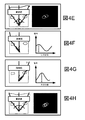
WME114の個々の小区域によって変調されるビームレットを共通焦点120にまとめるために、まず、対物レンズ118の後瞳が十分に照射される状態でサンプル106の参照画像が取得されることができる。例えば、図4Aに示すように、収差のある励起光のビームを用いて画像が作成されることができる。例えば、サンプル106内の蛍光ビーズは、参照画像を作成するために使用されることができる。適応光学系補正に選定される横方向画像平面は、蛍光参照ビーズなどのサンプル106内の関心対象の特徴の画像の三次元スタックを取得し、ユーザーが定義する関心対象の領域にわたって積分されたような信号が最大となる平面を選択することによって選択されることができる。おそらくは、この平面は最初の理想的な焦点に最も近く、したがって、回折限界性能を取り戻すために最小の補正で済むことになる。
In order to combine the beamlets modulated by the individual subregions of the
参照画像が取得された後、二進位相パターンがWME114のN個の小区域の1つを除くすべてに加えられることができる−これはN個の小区域の1つを除くすべてに関連するビームレットを中間画像平面における視野絞り122によって回折させ阻止させて、これらのビームレットを効果的に「オフ」にする(つまり、これらの小区域に当たる光は対物レンズ118に達しない)パターンである。ビームレットは、ビームレットに関連するWME114の小区域に0およびπの位相シフトの交互の列からなる位相格子を適用することによって「オフ」にされることができる。この位相格子は、これらの小区域によって変調されるビームレットの光のほとんどを、中間画像平面で視野絞り122の中で回折させ、光が遮断される。
After the reference image is acquired, a binary phase pattern can be applied to all but one of the N subregions of WME 114-this is the beam associated with all but one of the N subregions. The pattern is diffracted and blocked by the
この後、サンプルの画像(例えば、サンプル内の蛍光ビーズの画像)が、唯一の残る「オン」ビームレットを用いて取得されることができる。ビームレットを理想的な焦点から偏向させる唯一の残る「オン」ビームレットの経路に沿った不均一性は、参照画像に対するこの画像内のシフトとして明らかになる。例えば、図4Bに示すように、図4Bに示すビームレットのみから励起光によって作り出されるサンプル内の蛍光ビーズの画像が、図4Aに示すように、収差のある励起光のすべてのビームレットから作り出される画像(点線参照)から上および左に変位される。例えば、図4Cに示すように、図4Cに示すビームレットのみから励起光によって作り出されるサンプル内の蛍光ビーズの画像が、図4Aに示すように、収差のある励起光のすべてのビームレットから作り出される画像(点線参照)の中心にある。例えば、図4Dに示すように、図4Dに示すビームレットのみからの励起光によって作り出されるサンプル内の蛍光ビーズの画像が、図4Aに示すように、収差のある励起光のすべてのビームレットから作り出される画像(点線参照)から上および右に変位される。 After this, an image of the sample (eg, an image of the fluorescent beads in the sample) can be acquired using the only remaining “on” beamlet. The non-uniformity along the path of the only remaining “on” beamlet that deflects the beamlet from the ideal focus is manifested as a shift in this image relative to the reference image. For example, as shown in FIG. 4B, an image of fluorescent beads in the sample created by excitation light from only the beamlet shown in FIG. 4B is produced from all beamlets of aberrant excitation light as shown in FIG. 4A. Displaced up and left from the image (see dotted line). For example, as shown in FIG. 4C, an image of fluorescent beads in a sample created by excitation light from only the beamlet shown in FIG. 4C is produced from all beamlets of aberrant excitation light as shown in FIG. 4A. In the center of the image (see dotted line). For example, as shown in FIG. 4D, an image of fluorescent beads in the sample created by excitation light from only the beamlet shown in FIG. 4D can be obtained from all beamlets of aberrant excitation light as shown in FIG. 4A. Displaced up and right from the created image (see dotted line).
簡単な単独の物体の場合、唯一のビームレットからの励起光によって作り出される画像のシフトは画像内の物体における重心のシフトから決定されることができるが、多くの複雑なサンプルの場合、画像相関がシフトを決定するために用いられることができる。さらに複雑なサンプルでは、サンプル内の複数の特徴の画像相関は、種々の瞳のセグメントが作動させられるときに画像シフトを測定するために用いられることができる。例えば、サンプルにおける複数の蛍光ビーズなどの特徴の画像は、ビームレットを共通焦点に導くために比較されて用いられることができる。また、画像相関は、任意の蛍光パターンを有する複雑な生物組織内での適応光学系技術の適用を可能にする。 In the case of a simple single object, the image shift created by the excitation light from a single beamlet can be determined from the shift of the centroid in the object in the image, but for many complex samples, the image correlation Can be used to determine the shift. For more complex samples, the image correlation of multiple features in the sample can be used to measure image shift as the various pupil segments are activated. For example, images of features such as multiple fluorescent beads in a sample can be compared and used to direct the beamlet to a common focus. Image correlation also allows the application of adaptive optics technology in complex biological tissues with arbitrary fluorescence patterns.
ビーム偏向測定に画像相関を使用する1つの利点は、ユーザーによって選択された相関領域全体にわたる平均収差を測定することであり、したがって、その領域全体にわたって有効な適応光学系補正を提供することである。対応する欠点は、測定された収差が大量の生物組織に関する光学特性の平均値を表すので、これはローカル的屈折率プロファイルが測定平均値と異なる特殊な小区域での最適補正よりも低くなる可能性があるということである。このような領域では、ローカル画像相関またはローカル的特徴の重心推定のいずれかを用いたさらにローカル的な測定が要求されるかもしれない。この後、比較的大きい視野画像は、各々が固有の補正波面で作り出される比較的小さいサブ画像からまとめられることができる。 One advantage of using image correlation for beam deflection measurements is to measure the average aberration across the correlation region selected by the user and thus provide effective adaptive optics correction across that region. . The corresponding disadvantage is that the measured aberration represents the average value of the optical properties for a large amount of biological tissue, so this can be lower than the optimal correction in special subregions where the local refractive index profile differs from the measured average value It is that there is sex. In such regions, more local measurements using either local image correlation or local feature centroid estimation may be required. After this, a relatively large field image can be combined from relatively small sub-images, each created with a unique correction wavefront.
いずれにしても、収差のない方向からの個々のビームレットの傾斜角のシフトが検知された時点で、ビームレットの所望の方向からのビームレットの偏向角度が計算されてもよく、大きさが等しい対頂角がWME114の対応する小区域に適切な位相ランプを適用することによってビームレットに与えられてもよい。
In any case, the deflection angle of the beamlet from the desired direction of the beamlet may be calculated and detected when a shift in the tilt angle of the individual beamlet from the direction without aberration is detected. An equal vertical angle may be provided to the beamlet by applying an appropriate phase ramp to the corresponding sub-region of
このプロセスは、この後、すべてのN個のビームレットが図4Eに示すように共通焦点で交わるまで、WME114の他のN−1個の小区域、および他のN−1個の対応するビームレットに対して繰り返されることができる。N個の小区域に関する傾斜角測定の場合、同時に「オン」であるのは1つの小区域のみであるという事実を補償するために、出力が最初に少なくともN倍に増加されることができる。WME114全体のガウス強度変動に起因して、画像変位を正確に測定すべく、ただしサンプル106で過度な光退色を生じない程度に、十分な信号を得るために必要に応じて各小区域でさらなる出力調整が自動的に行われることができる。
This process is then followed by other N−1 subregions of
つぎに、ビームレットの位相を補正するために、参照ビームレットが他のN−1個のビームレットの1つとともに「オン」にされることができる。この後、図4Fに示すように、焦点における信号が最大になるまで第2のビームレットに与えられる複数の異なる位相を有する一連の画像が取得されることができる。この後、このプロセスは、同じ参照ビームレットを用いて、さらには、残るN−2個のビームレットの各々を用いて、図4Gに示すように繰り返されることができる。この後、適応光学系アルゴリズムが終了し、Nが十分に大きければ、励起光ビームのビームレットは共通焦点においてすべて交わるとともに、回折限界焦点が実現されるように焦点において互いに同相である。異なる個々のビームレットの相対位相を補正するとき、励起光の特定ビームレット出力は十分な信号を実現するが、光退色を回避するために、必要に応じて調整されることができる。光退色をさらに最小にするために、4〜7個の画像のみが各小区域に対して0と2πの間の等間隔位相オフセットで取得されてもよい。この後、これらの画像の各々からの焦点における信号を、関数S=|1+αexp(i(φ−φ0))|4にフィットさせることによって、最大建設的干渉に対する正確な位相オフセットφ0が決定されてもよく、ここで、Sは現在の小区域からの電場と参照小区域またはすべての他の小区域のいずれかからの電場との干渉から生じる2つの光子信号を表す。 The reference beamlet can then be turned “on” along with one of the other N−1 beamlets to correct the beamlet phase. Thereafter, as shown in FIG. 4F, a series of images having a plurality of different phases applied to the second beamlet can be acquired until the signal at the focal point is maximized. This process can then be repeated as shown in FIG. 4G using the same reference beamlet and further using each of the remaining N-2 beamlets. After this, the adaptive optics algorithm ends and if N is sufficiently large, the beamlets of the excitation light beam all intersect at the common focus and are in phase with each other at the focus so that a diffraction limited focus is achieved. When correcting the relative phase of different individual beamlets, the specific beamlet output of the excitation light provides a sufficient signal, but can be adjusted as needed to avoid photobleaching. To further minimize photobleaching, only 4-7 images may be acquired with equally spaced phase offsets between 0 and 2π for each subregion. Thereafter, the signal at the focus from each of these images, the function S = | determined by fitting the 4, accurate phase offset phi 0 to the maximum constructive interference | 1 + αexp (i (φ -φ 0)) Where S represents the two photon signals resulting from the interference of the electric field from the current subregion with the electric field from either the reference subregion or all other subregions.
別の実施形態では、個々のビームレットの位相を補正するために、個々のビームレットを共通焦点において一緒に交わらせるためにWME114によって適用されるビーム偏向角に関する情報が、対物レンズの後瞳全体の位相勾配測定値のアレイを規定するために使用されることができる。これらの位相勾配測定値から、焦点120において個々のビームレットが建設的に干渉するために必要な後瞳における個々のビームレットの相対位相は、非特許文献1に記載されて本明細書で参照によって援用されるように、波面全体の位相の既知の空間的連続性に基づく反復アルゴリズムによって決定されうる。
In another embodiment, information about the beam deflection angle applied by the
「オン」の小区域では、WMEがSLMなどの反射素子を含むとき、制御不可能であるWMEの前面から鏡面的に反射されるほんの僅かな光からWME114内で変調される光の大部分を分離するために、緩やかでグローバルな位相ランプを適用することができる。適応光学系補正の後、WME114の各小区域に固有の別のローカル位相ランプが、サンプル106において回折限界焦点120を作り出すために必要な個々のビームレットの傾斜角および位相に必要な補正をもたらすためにグローバルな位相ランプに重畳されうる。一実施形態では、WMEの個々の画素は、256の異なるグレースケール値の1つでプログラムされることができる。WMEを制御するために使用される8ビット・グレースケール・レベルとピクセルによって変調されたビームレットにもたらされた実際の位相シフトとの関係は、メーカーの推奨値に従って較正によって決定される。
In the “on” sub-region, when the WME includes a reflective element such as an SLM, most of the light modulated in the
適合光学系プロセスの傾斜角と位相測定値部分の両方に対して、すべての小区域が「オフ」の背景画像が出力レベルが変更されるときには必ず取得されてもよく、背景画像は測定値の精度を保証するために同じ出力レベルで取得されたすべての後続画像から差し引かれてもよい。 For both the tilt and phase measurements portion of the adaptive optics process, a background image with all sub-areas “off” may be acquired whenever the output level is changed, and the background image It may be subtracted from all subsequent images acquired at the same output level to ensure accuracy.
単一の「オン」小区域は、対物レンズ118の全NAの〜
![]()
![]()
それにもかかわらず、励起ビームで得られる出力の大きさはやはりビーム偏向測定値の数、従って提供されうる補正の複雑さに実際の制限を課し、後瞳がN個の非重複小区域に分割されるとき一度にオンになるのはその1つのみである(以後、「独立マスクアプローチ」と称する)。比較的高いNをもたらす代替的な方策(以後、「重複マスクアプローチ」と称する)は、一連の重複マスクにおける小区域の隣接するグループをオンにすることを含み、各マスクはWME114の任意の単一の小区域に対応する後瞳領域よりも大きい後瞳領域のほんの一部である1/Mに対応し、それによって著しく強力な焦点を作り出す。ビーム偏向および位相オフセットは、前述のように各マスクに対して測定され、各小区域が固有の1組のマスクによってサンプリングされ、各小区域において固有の補正位相が得られるまで種々のマスクが適用される。
Nevertheless, the magnitude of the power obtained with the excitation beam still imposes a practical limit on the number of beam deflection measurements, and thus the correction complexity that can be provided, so that the back pupil is reduced to N non-overlapping subregions. Only one of them is turned on at a time when it is split (hereinafter referred to as the “independent mask approach”). An alternative strategy that yields a relatively high N (hereinafter referred to as a “duplicate mask approach”) involves turning on adjacent groups of subregions in a series of duplicate masks, each mask being an arbitrary unit of
図5a、5b、5c、及び5dは、適応光学系補正に対する独立、重複、および段階的重複マスクアプローチの例を提供する。対物レンズ118の後瞳は図において大きい方形で表され、網掛けされた長方形はビーム偏向測定中に特定点においてオンにされる瞳のほんの一部を表す。図5a及び5bに示す独立マスクアプローチでは、対物レンズ118の後瞳は非重複領域にセグメント化される。各領域、すなわち「マスク」は、ビーム偏向測定中に個々に「オン」にされる。マスクされた各小区域における補正波面は、すべての他の区域における平面から独立した平面によって推定される。図5aは独立したマスクアプローチを示し、ここでは、各々が全瞳領域の1/3に対応するWME114に対する3つの非重複マスクがビーム偏向を独立に測定し、3つの瞳小区域の各々における収差を補正する。図5bは独立マスクアプローチを示し、ここでは、各々が瞳領域の1/9に対応するWME114に対する9つの非重複マスクがビーム偏向を独立に測定し、9つの瞳小区域の各々における収差を補正する。
FIGS. 5a, 5b, 5c, and 5d provide examples of independent, overlapping, and stepwise overlapping mask approaches for adaptive optics correction. The rear pupil of the
図5cに示す重複マスクアプローチでは、ビーム偏向測定中に個々に「オン」となるマスクは他のマスクと重複する。その結果、最終補正波面における平面小区域の全数は、マスク領域に対する瞳領域の比よりも大きい。しかしながら、これらの小区域における位相の最終値は、マスクの重複によって互いに完全に独立でないかもしれない。他方、所与のマスク領域の場合、あるいは同じことであるが、所与のレーザー出力の場合、重複マスクには、さらに多くの小区域を使用することができ、それゆえ、優れた補正が得られる場合が多い。従って、図5cは重複マスクアプローチを示し、ここでは、各々が瞳領域の1/3をカバーするWME114に対する6つの重複マスクによって9つの異なる瞳小区域の各々に対する固有の波面推定値が得られる。
In the overlapping mask approach shown in FIG. 5c, masks that are individually “on” during beam deflection measurements overlap with other masks. As a result, the total number of planar subregions in the final corrected wavefront is greater than the ratio of the pupil region to the mask region. However, the final values of the phases in these subregions may not be completely independent of each other due to mask overlap. On the other hand, for a given mask area, or the same thing, but for a given laser power, more sub-areas can be used for overlapping masks, thus obtaining better correction. It is often done. Thus, FIG. 5c shows an overlap mask approach, where six overlap masks for
最後に、図5dに示す段階的な重複マスクアプローチでは、マスクは同じ寸法を有するが、マスクの寸法よりも小さい距離で隣接するマスクから離される。例えば、図5dに記載するパターンは、3×3および2×1の段階的な重複マスクで示され、ここで、「3×3」は各マスクの寸法(後瞳に亘るための3つの水平マスク×3つの垂直マスク)を示し、「2×1」は段階的パターン(各マスクの幅を横断するための2ステップと高さをカバーするための1ステップ)を示す。このアプローチは、位相勾配データの高密度アレイを一定間隔で測定できるので、位相復元に特によく適している。それゆえ、段階的重複アプローチでは、収差のある波面は、小区域そのものよりも小さい一連の離散ステップで小区域を移動し、各ステップでビーム偏向、したがって位相勾配を測定することによって、単一の「オン」小区域のサイズよりも小さいスケールで測定されることができる。図5dは段階的重複マスクアプローチを示し、ここでは、瞳領域の1/9をカバーするWME114のマスクは、マスクの幅の半分に等しい水平ステップと、マスクの高さに等しい垂直ステップとで移動される。ビーム偏向は、マスクの各位置で測定される。それゆえ、図5dは、瞳領域の1/9に対応するマスクが18の異なる瞳小区域の各々に固有の波面推定をもたらすように、3×3および2×1の段階的重複マスクとして示される。位相復元は、段階的重複マスクの各位置における最適な位相オフセットを決定するために使用されてもよく、各測定点を中心とする領域において収差がある波面に最適な平面を決定するために勾配データと結合されてもよい。
Finally, in the stepped overlap mask approach shown in FIG. 5d, the masks have the same dimensions, but are separated from adjacent masks by a distance that is less than the mask dimensions. For example, the pattern described in FIG. 5d is shown with 3 × 3 and 2 × 1 graded overlapping masks, where “3 × 3” is the dimension of each mask (three horizontal to span the posterior pupil). “2 × 1” indicates a stepped pattern (2 steps to cross the width of each mask and 1 step to cover the height). This approach is particularly well suited for phase reconstruction because a dense array of phase gradient data can be measured at regular intervals. Therefore, in a step-by-step approach, an aberrated wavefront moves through a small area in a series of discrete steps that are smaller than the small area itself, and measures the beam deflection, and thus the phase gradient, at each step. It can be measured on a scale smaller than the size of the “on” subregion. FIG. 5d shows a stepped overlap mask approach, where the
重複および段階的重複マスクアプローチは、例えば、後瞳のN=81小区域が後瞳の領域の1/9に対応するマスクを用いて規定されるように、さらに拡張されることができる。当然ながら、所与の数Nの小区域の場合、独立したマスクアプローチは、小区域間の結合が残留する重複および段階的重複マスクアプローチよりも優れている。しかしながら、所与のマスク領域の場合、あるいは同じことであるが、所与のレーザー出力の場合、重複または段階的重複マスクには、さらに多くの小区域を使用することができ、それゆえ、優れた補正が得られる場合が多い。 The overlap and stepped overlap mask approach can be further extended, for example, such that the N = 81 subregion of the back pupil is defined with a mask corresponding to 1/9 of the back pupil region. Of course, for a given number N of subregions, the independent mask approach is superior to the overlap and stepwise overlap mask approach where the connections between subregions remain. However, for a given mask area, or the same thing, but for a given laser power, more sub-areas can be used for overlapping or stepped overlapping masks, and therefore better Correction is often obtained.
サンプル106の焦点120における励起ビーム光の収差の低減と、サンプルから得られる結果として生じる画像の改善とは、通常WME114の小区域数Nの関数として単調増加し、Nは対物レンズ118の後瞳の個々のセグメントに対応するが、Nのある値において分解能と信号強度の改善は限界に達する。良好な結果を実現するために必要な小区域の数Nは、調査中のサンプルと、最適化されているパラメータと、所望の最適化度との詳細に依存する。当然ながら、対物レンズ118の後瞳の個々のセグメントに対応するWME114の小区域の密度は、WME全体で均一である必要はない。むしろ、収差がある波面の初期の低分解能マップは低い値のNを用いて作成されてもよく、この後、微細構造を示唆する領域が高密度の小区域を用いてサンプリングされてもよい。
The reduction of the aberration of the excitation beam light at the
顕微鏡システム100の性能に影響を与える収差は、サンプル160自体からと同様に、光源102と焦点120との間の光路に沿ってどこからでも由来することができる。それゆえ、これらの本質的な顕微鏡収差は、後続の実験における全測定収差のサンプルによって誘導された成分を導出しうるように特徴づけられることができる。例えば、画像は蛍光ビーズ参照物体について取得されてもよく、また画像はWME114の平坦性の乏しさに大きく起因する可能性のある著しい非点収差およびコマ収差を示してもよい。しかしながら、N=36の独立した小区域を有する本明細書に記載する適応光学系補正と直接位相測定を適用した後、横(X−Y平面)方向および軸(X−Z、Y−Z、長軸Z、および短軸−Z平面)方向の両方のビーズ画像の半値全幅(FWHM)はそれらの回折限界値に近づきうる。
Aberrations that affect the performance of the
適応光学系プロセスが終了し、回折限界焦点120を実現するために対物レンズ118の後瞳における適切な角度と位相とを有する個々のビームレットを生じるWME小区域に適用される位相が決定された後、WME114の位相パターンは、最終補正波面、モジュロ2πを表す。この波面をより直感的な形で表示するために、測定中に使用されるグローバルな位相ランプが差し引かれ、位相は、縁をカウントし位相が小区域境界を越えて連続するものと仮定することによって明らかにされる。最後に、サンプルのみによる収差を決定するために、システム収差に起因する明らかにされた波面の一部が差し引かれる。
The adaptive optics process is finished and the phase applied to the WME subregion that yields individual beamlets with the appropriate angle and phase at the back pupil of the
前述のように、適応光学系は、ポイントスキャン顕微鏡検査法に使用されることに加えて、広視野顕微鏡検査法によって得られる画像の品質を向上させるためにも使用されることができる。広視野顕微鏡検査法では、サンプルの大きい区域が均一に照射され、関心区域全体が画像検出器(例えば、CCDカメラ)に同時に記録される。多くのポイントスキャン法の場合、収差の主要な影響は励起光にあり、回折限界焦点が形成されることを阻止する。前述のように、収差の主要な影響は、さらに、放射経路にあり、サンプル内の各点から放射される信号が画像検出器の回折限界点に再収束されことを阻止する。ポイントスキャン顕微鏡検査法は散乱生物組織に好ましく、広視野走査顕微鏡検査法は透明な生物サンプルに、より一般的に適用されるが、サンプルによって誘発される収差はいずれにしてもよく見られる。 As previously mentioned, adaptive optics can be used to improve the quality of images obtained by wide field microscopy in addition to being used for point scan microscopy. In wide-field microscopy, a large area of the sample is illuminated uniformly and the entire area of interest is recorded simultaneously on an image detector (eg, a CCD camera). For many point scan methods, the main effect of aberrations is on the excitation light, preventing the formation of a diffraction limited focus. As mentioned above, the main effect of aberrations is also in the radiation path, preventing the signal emitted from each point in the sample from refocusing to the diffraction limit point of the image detector. Point-scan microscopy is preferred for scattered biological tissue, and wide-field scanning microscopy is more commonly applied to transparent biological samples, although the sample-induced aberrations are common.
例えば、図6に示すように、放射光の球面波面はサンプル604において点602から放射されることができる。波面はサンプル604における屈折率の不均質性によって歪められうる(すなわち、収差を生じる)。この後、収差を生じた波面を顕微鏡対物レンズ606によって収束させると、結果的に平面波ではなく、収差を生じた波面608を生じる。 For example, as shown in FIG. 6, a spherical wavefront of the emitted light can be emitted from a point 602 at a sample 604. The wavefront can be distorted (ie, produces aberrations) by refractive index inhomogeneities in sample 604. After that, when the wavefront having an aberration is converged by the microscope objective lens 606, a wavefront 608 having an aberration is generated instead of a plane wave.
ポイントスキャン顕微鏡検査法と違って、従来の広視野顕微鏡検査法はオプティカルセクショニング能力を欠いている。それゆえ、これは、通常、単一の培養細胞および極薄組織切片に使用され、この場合、収差は典型的に問題ではない。しかしながら、選択的平面照明顕微鏡検査法(「SPIM」)および構造化照明顕微鏡検査法(「SIM」)などの軸方向切断能力を有する広視野法の最近の開発によって、厚いサンプルへの適用が現在では可能であり、したがって、放射光の収差の補正が現実味を帯びている。 Unlike point scan microscopy, traditional wide-field microscopy lacks optical sectioning capability. Therefore, it is usually used for single cultured cells and ultrathin tissue sections where aberrations are typically not a problem. However, recent developments in wide-field methods with axial cutting capabilities, such as selective planar illumination microscopy (“SPIM”) and structured illumination microscopy (“SIM”), are currently being applied to thick samples. Therefore, correction of the aberration of the emitted light is realistic.
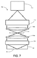
図7は、適応光学系技術を用いて収差を補正する広視野顕微鏡システム700の概略図である。放射光はシステム700の焦点面704から放射され、この場合、焦点面はサンプル702内にある。対物レンズ706は、サンプル702を通過することによって収差を受ける可能性のある放射光の焦点を合わせ、1対の望遠レンズ708a、708bは収束された光を視野絞り710に通して放射光ビームのウエストを拡大または縮小するために使用されることができる。波面変調素子712によって、この後、放射光を検出器714に通す前に、収差がある波面に適応光学系技術が適用される。WME712によって、ポイントスキャン顕微鏡検査法に関して前述した同様の適応光学系瞳セグメンテーション技術を適用してもよく、波面の複数の異なる部分で形成された画像を回折限界の完全な広視野波面を復元するために使用できるように、焦点面704からの放射光ビームのビームレットの角度に個々のシフトを適用してもよい。
FIG. 7 is a schematic diagram of a wide
図8は、適応光学系技術を用いて収差を補正し、システム700のさらなる詳細を示す広視野顕微鏡システム800の概略図である。励起光源802は、移動ステージ808に取り付けられた対物レンズ806を通ってビームスプリッタ804からサンプル810に反射される励起光を提供する。放射光は、対物レンズ806の焦点面でサンプル810から放射され、対物レンズ806によって放射光ビームに収束され、望遠レンズシステム814a、814bに向かってミラー812から反射される。望遠レンズ814a、814bは、放射光ビームを視野絞り816に通す。前述したポイントスキャン顕微鏡検査法で使用される適応光学系と同様に、波面変調素子818は、放射光ビームの個々のビームレットを修正するための波面センサーおよび位相制御デバイスの両方としての機能を果たす。WME818によって変調される放射光は、放射光を画像化する検出器820(例えば、CCD検出器)に向けられる。
FIG. 8 is a schematic diagram of a wide
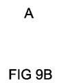
図9Aに示すような一実施形態では、単一のフレネル・レンズ・パターンがWME818に適用されることができる。フレネル・レンズ・パターンは、この後、図9Bに示すように、サンプル810の単一画像を形成するために放射ビームを検出器820に収束させる。この後、図9Cに示すように、フレネルレンズのアレイがWME818の複数の異なる小区域に適用されて、放射光波面を、複数の異なる、個々に制御可能なビームレットにセグメント化し、図9Dに示すように、検出器820の画像平面でサンプルの画像のアレイを作り出すことができる。完全な平面波放射波面の場合、画像のアレイは、完全な格子に位置することになる。しかしながら、その理想的な格子位置からの個々の画像のずれは、個々の画像を作成するために使用される波面の部分の傾斜(及び、波面のその部分に対応するビームレットの角度)を測定するために使用されることができる。それゆえ、その理想的な格子位置からの個々の画像のずれの測定は、対物レンズ806の後瞳全体の波面傾斜測定値のアレイを決定するために使用されてもよく、それから所望の補正波面が復元されてもよい。この補正をWME818に適用し、これに図9Aに示す単一のフレネル・レンズ・パターンを重ね合わせ、これを使用して画像全体を検出器に収束させると、サンプル810の回折限界画像が検出器820で復元される。
In one embodiment as shown in FIG. 9A, a single Fresnel lens pattern can be applied to the
2光子蛍光顕微鏡検査法と同様に、サンプル810が視野位置に依存する収差を示さない場合、結果として得られる適応光学系補正は視野のいたるところで回折限界分解能を復元することが可能である。収差が視野に依存する場合、視野全体に対して平均化された補正が得られ、これは信号および分解能をさらに改善することが可能である。さらに、複数の異なる部分的視野内の蛍光の特徴を用いた画像シフトを解析することによって、視野に依存する収差が測定されてもよく、適切な収差パターンを各部分的視野に順次適用することによって回折限界画像が復元されてもよい。
Similar to two-photon fluorescence microscopy, if the
図10は、サンプルの画像を形成するプロセス1000のフローチャートである。プロセス1000では、励起光ビームがサンプル内の焦点に収束される(1002)。そして、ビームの断面は個々のビームレットを含む。焦点が、サンプル内の複数の異なる位置で走査される(1004)。個々のビームレットの角度は、焦点が複数の異なる位置にあるとき個々に制御される(1006)。個々のビームレットの角度を個々に制御するステップは、個々のビームレットに対応する個々の小区域を含む波面変調素子で励起ビームを変調するステップ(1006a)を含んでいてもよく、個々の小区域内で対応する個々のビームレットの位相に空間的勾配を誘導するために対応するビームレットに小区域によって与えられる位相値のプロファイルを制御するステップ(1006b)を含んでいてもよい。
FIG. 10 is a flowchart of a
位相値のプロファイルは、個々のビームレットを物体に照射することによって形成される物体の位置画像のシフトを観察することによって決定されることができる。例えば、サンプル内の参照物体には、励起ビームの複数の異なるビームレットが照射されてもよく、その場合、複数の異なるビームレットは、波面変調素子の種々の対応する小区域によって変調される。参照物体からの放射光は、参照物体に複数の異なるビームレットが照射されるときに検出されてもよく、サンプル内の参照物体の位置は参照物体に複数の異なるビームレットが照射されるときに検出される放射光に基づいて決定されてもよい。決定された位置に基づいて、ビームレットが位相に空間的勾配を含むときに位置が実質的に互いに等しくなるように、対応するビームレットの位相に空間的勾配を誘導するために、小区域の対応するビームレットに各小区域によって与えられる位相値のビームレット−角度−補正プロファイルについての決定がなされることができる。 The profile of the phase value can be determined by observing the shift of the position image of the object formed by irradiating the object with individual beamlets. For example, the reference object in the sample may be irradiated with a plurality of different beamlets of the excitation beam, where the different beamlets are modulated by various corresponding subregions of the wavefront modulation element. The emitted light from the reference object may be detected when the reference object is irradiated with a plurality of different beamlets, and the position of the reference object in the sample is when the reference object is irradiated with a plurality of different beamlets. It may be determined based on the detected radiation. Based on the determined position, in order to induce a spatial gradient in the phase of the corresponding beamlet so that the positions are substantially equal to each other when the beamlet includes a spatial gradient in the phase, A determination can be made about the beamlet-angle-correction profile of the phase value provided by each subregion to the corresponding beamlet.
個々のビームレットの相対位相は、焦点が複数の異なる位置にあるときに個々に制御される(1008)。例えば、焦点におけるビームレット間に建設的干渉をもたらすことになる波面変調素子におけるビームレット間の相対位相は、位相値のビームレット−角度―補正プロファイルに基づいて決定されることができる。焦点から放射される放射光は、焦点が複数の異なる位置にあるときに検出される(1010)。焦点の複数の異なる位置から検出された放射光に基づいてサンプルの画像が作成される(1012)。 The relative phase of the individual beamlets is individually controlled when the focus is at a plurality of different positions (1008). For example, the relative phase between beamlets in a wavefront modulation element that will cause constructive interference between beamlets at the focal point can be determined based on the beamlet-angle-correction profile of the phase value. The emitted light emitted from the focal point is detected 1010 when the focal point is at a plurality of different positions. An image of the sample is created based on the emitted light detected from a plurality of different positions of the focal point (1012).
図11は、サンプルの画像を形成するプロセス1100のフローチャートである。プロセス1100では、サンプルに励起光が照射され(1102)、サンプルによって放射される光は対物レンズで集められる(1104)。集められた光のビームは波面変調素子によって変調され、この場合、変調された光のビームの断面は個々のビームレットを含む(1106)。個々のビームレットが変調される角度は、波面変調素子の異なる個々の小区域によって個々に制御される(1108)。個々のビームレットの角度を個々に制御するステップは、個々のビームレットに対応する波面変調素子の個々の小区域内で、個々の対応するビームレットの位相に空間的勾配を誘導するために、小区域によって対応するビームレットに与えられる位相値のプロファイルを制御する(1108b)ステップを含むことができる。波面変調素子によって変調される光は画像化される(1110)。
FIG. 11 is a flowchart of a
ビームレットが個々の小区域によって変調される位相値のプロファイルは、波面変調素子にフレネルレンズのパターンを与えることによって決定されてもよく、その場合、複数の異なるフレネルレンズは波面変調素子の複数の異なる小区域に与えられる。サンプル内の参照物体には励起光が照射されてもよく、参照物体によって放射される光は、フレネルレンズのパターンが波面変調素子に与えられる間に集められてもよい。集められた光のビームはフレネルレンズのパターンが与えられる間に波面変調素子で変調されてもよく、この場合、変調され集められた光のビームの断面は個々のビームレットを含む。集められて変調された光は画像化されてもよく、画像化された光における参照物体の画像パターンの位置特徴は参照物体の画像の理想パターンの位置特徴と比較されてもよい。比較に基づいて、2つのパターンの差を減らすことになる位相値のプロファイルが決定されることができる。 The profile of the phase value at which the beamlet is modulated by individual sub-regions may be determined by providing the wavefront modulation element with a Fresnel lens pattern, in which case multiple different Fresnel lenses are provided for the plurality of wavefront modulation elements. Given to different subregions. The reference object in the sample may be irradiated with excitation light, and the light emitted by the reference object may be collected while the Fresnel lens pattern is applied to the wavefront modulation element. The collected light beam may be modulated with a wavefront modulation element while the Fresnel lens pattern is applied, in which case the cross-section of the modulated and collected light beam includes individual beamlets. The collected and modulated light may be imaged and the position features of the image pattern of the reference object in the imaged light may be compared with the position features of the ideal pattern of the image of the reference object. Based on the comparison, a profile of phase values that will reduce the difference between the two patterns can be determined.
本明細書に記載する様々な技術の実施形態は、ディジタル電子回路、またはコンピュータハードウェア、ファームウェア、ソフトウェア、あるいはこれらの組合せで実施されることができる。実施形態は、コンピュータプログラム製品、すなわち、情報担体において、例えば、機械で読取可能な記憶デバイスにおいて、または伝播信号において、データ処理装置、例えば、プログラマブルプロセッサ、コンピュータ、または複数のコンピュータによって実行するために、あるいはこれらの動作を制御するために、明白に具体化されるコンピュータプログラムとして実施されてもよい。前述したコンピュータプログラムなどのコンピュータプログラムは、コンパイラ型言語、インタープリタ型言語を含む任意の形のプログラミング言語で書かれることができ、スタンドアロンプログラムとして、あるいはモジュール、コンポーネント、サブルーチン、またはコンピュータ環境での使用に適した他のユニットとしてなど、任意の形で展開されることもできる。コンピュータプログラムは、1つのサイトまたは複数サイトに分散された、1台のコンピュータあるいは複数台のコンピュータで、通信ネットワークによって相互接続されて、実行されるように展開されうる。 Embodiments of the various techniques described herein can be implemented in digital electronic circuitry, or computer hardware, firmware, software, or combinations thereof. Embodiments are for execution by a data processing apparatus, eg, a programmable processor, a computer, or multiple computers, in a computer program product, ie, an information carrier, eg, in a machine-readable storage device, or in a propagated signal. Alternatively, it may be implemented as a computer program that is explicitly embodied to control these operations. Computer programs such as the computer programs described above can be written in any form of programming language, including compiler-type languages, interpreted languages, and can be used as stand-alone programs or in modules, components, subroutines, or computer environments. It can also be deployed in any form, such as a suitable other unit. The computer program can be deployed to be executed by being interconnected by a communication network on one computer or a plurality of computers distributed at one site or a plurality of sites.
方法のステップは、入力データで動作し出力を発生することによって機能を実施するためにコンピュータプログラムを実行する1つまたは複数のプログラマブルプロセッサによって実施されてもよい。さらに、方法のステップは、特殊目的論理回路、例えば、FPGA(フィールド・プログラマブル・ゲート・アレイ)またはASIC(特定用途向け集積回路)によって実施されてもよく、また、装置はこれらとして実現されてもよい。 The method steps may be performed by one or more programmable processors executing a computer program to perform functions by operating on input data and generating output. Furthermore, the steps of the method may be performed by special purpose logic circuits, such as an FPGA (Field Programmable Gate Array) or ASIC (Application Specific Integrated Circuit), and the device may be implemented as these. Good.
コンピュータプログラムの実行に適したプロセッサは、例として、汎用および専用の両マイクロプロセッサと、あらゆる種類のディジタルコンピュータのいずれか1つまたは複数のプロセッサとを含む。一般に、プロセッサは、リード・オンリー・メモリまたはランダム・アクセス・メモリまたは両方から命令およびデータを受け取る。コンピュータの要素は、命令を実行する少なくとも1つのプロセッサと、命令およびデータを記憶する1つまたは複数のメモリデバイスを含んでいてもよい。また、一般に、コンピュータは、データを記憶する1つまたは複数の大容量記憶装置、例えば、磁気ディスク、光磁気ディスク、または光ディスクを含んでいてもよく、あるいはこれらからデータを受け取り、またはこれらにデータを転送し、またはこれらの両方を行うように動作可能に結合されてもよい。コンピュータプログラム命令およびデータを具体化するのに適した情報担体は、例として、半導体メモリデバイス、例えば、EPROM、EEPROM、およびフラッシュ・メモリ・デバイス;磁気ディスク、例えば、内蔵ハードディスクまたはリムーバブルディスク;光磁気ディスク;およびCD−ROMおよびDVD−ROMディスクなど、あらゆる形態の不揮発性メモリを含む。プロセッサおよびメモリは、専用論理回路によって補完されてもよく、専用論理回路に組み込まれてもよい。 Processors suitable for the execution of computer programs include, by way of example, both general and special purpose microprocessors, and any one or more processors of any kind of digital computer. Generally, a processor will receive instructions and data from a read-only memory or a random access memory or both. The elements of the computer may include at least one processor that executes instructions and one or more memory devices that store instructions and data. Also, in general, a computer may include one or more mass storage devices that store data, such as a magnetic disk, a magneto-optical disk, or an optical disk, or receive data from or receive data from them. May be operatively coupled to transfer or both. Information carriers suitable for embodying computer program instructions and data include, by way of example, semiconductor memory devices such as EPROM, EEPROM, and flash memory devices; magnetic disks such as internal hard disks or removable disks; magneto-optical Disk; and all forms of non-volatile memory, including CD-ROM and DVD-ROM disks. The processor and the memory may be supplemented by a dedicated logic circuit or may be incorporated in the dedicated logic circuit.
ユーザーとの対話を行うために、実施形態は、表示装置、例えば、ユーザーに対して情報を表示するブラウン管(CRT)または液晶ディスプレイ(LCD)モニタと、キーボードおよびポインティングデバイス、例えば、ユーザーがコンピュータに入力を提供することができるマウスまたはトラックボールを有するコンピュータで実施されてもよい。ユーザーとの対話を行うために他の種類のデバイスも使用されることができる。例えば、ユーザーに提供されるフィードバックは、任意の形態の感覚フィードバック、例えば、視覚フィードバック、聴覚フィードバック、または触覚フィードバックであってもよく、ユーザーからの入力は音響、音声、触覚入力などのいかなる形態で受け取られてもよい。 In order to interact with a user, embodiments include a display device, such as a cathode ray tube (CRT) or liquid crystal display (LCD) monitor that displays information to the user, and a keyboard and pointing device, such as a user on a computer. It may be implemented on a computer having a mouse or trackball that can provide input. Other types of devices can also be used to interact with the user. For example, the feedback provided to the user may be any form of sensory feedback, e.g. visual feedback, auditory feedback, or haptic feedback, and input from the user is in any form such as acoustic, audio, haptic input, etc. May be received.
前述の実施形態の特定の特徴は本明細書で説明した通りであるが、ここで多くの修正形態、代替形態、変更形態、および等価物が当業者に想起されるであろう。そこで、添付の特許請求の範囲は実施形態の真の趣旨に含まれるすべての修正形態および変更形態を網羅するものであることを理解されたい。 Although the specific features of the foregoing embodiments are as described herein, many modifications, alternatives, variations and equivalents will now occur to those skilled in the art. Therefore, it is to be understood that the appended claims are intended to cover all modifications and changes that fall within the true spirit of the embodiments.
Claims (26)
前記サンプル内の焦点に、ビームの断面が個々のビームレットを含む、光源からの励起光ビームを収束させるステップと、
前記サンプル内の複数の異なる位置で前記焦点を走査するステップと、
前記焦点が前記複数の異なる位置にあるときに前記個々のビームレットの角度を独立に制御して、前記焦点における前記励起光の収差を低減させるステップであって、前記個々のビームレットの角度を独立に制御するステップは、
他のビームレットがオフの間に個々のビームレットをオンにし、前記サンプルを画像化して前記ビームレットに対する角度を決定するステップと、
前記個々のビームレットに対応する個々の小区域を含む波面変調素子で前記励起ビームを変調するステップと、
個々の小区域内で、前記対応する個々のビームレットの位相に空間的勾配を誘導するために前記対応するビームレットに前記小区域によって与えられる位相値のプロファイルを制御するステップと、を含むステップと、
前記焦点が前記複数の異なる位置にあるときに、前記焦点において前記個々のビームレットが互いに建設的に干渉するように、前記個々のビームレットの相対位相を独立に制御するステップと、
前記焦点が前記複数の異なる位置にあるときに前記焦点から放射された放射光を検出するステップと、
前記焦点の複数の異なる位置から前記検出された放射光に基づいて前記サンプルの画像を作成するステップと、
を備える、方法。 A method for forming an image of a sample, comprising:
Focusing an excitation light beam from a light source at a focal point within the sample, the beam cross-section comprising individual beamlets;
Scanning the focus at a plurality of different locations within the sample;
The focal point is independently controlled the angle of the individual beamlets when in the plurality of different positions, comprising the steps of Ru reduce aberrations of the excitation light at the focal point, the angle of the individual beamlets The step of independently controlling
Turning on individual beamlets while other beamlets are off, imaging the sample to determine an angle relative to the beamlets;
Modulating the excitation beam with a wavefront modulation element including individual subregions corresponding to the individual beamlets;
Controlling the profile of the phase value provided by the sub-region to the corresponding beamlet to induce a spatial gradient in the phase of the corresponding individual beamlet within the individual sub-region; and ,
Independently controlling the relative phase of the individual beamlets so that the individual beamlets constructively interfere with each other at the focal point when the focal point is at the plurality of different positions;
Detecting emitted light emitted from the focus when the focus is at the plurality of different positions;
Creating an image of the sample based on the detected radiation from a plurality of different positions of the focus;
A method comprising:
複数の異なる個々のビームレットが、前記波面変調素子の種々の対応する小区域によって変調され、前記サンプル内の参照物体に、前記励起ビームの複数の異なる個々のビームレットを照射するステップと、
前記参照物体に前記複数の異なる個々のビームレットが照射されるとき前記参照物体から放射光を検出するステップと、
前記参照物体に前記複数の異なる個々のビームレットが照射されるときに検出された前記放射光に基づいて前記サンプル内の前記参照物体の位置を決定するステップと、
前記決定された位置に基づいて、前記対応するビームレットの位相に空間的勾配を誘導するための前記小区域の対応するビームレットに各小区域によって与えられる位相値のビームレット−角度−補正プロファイルを決定し、前記ビームレットが前記位相に前記空間的勾配を含むときに前記位置が互いに実質的に等しくなるようにするステップと、
を含む、請求項1に記載の方法。 Determining a profile of the phase value, the determining step comprising:
A step different individual beamlets, said modulated by a variety of corresponding subregions of the wavefront modulation element, the reference object in the sample, irradiating the plurality of different individual beamlets of the excitation beam,
Detecting radiation from the reference object when the reference object is illuminated with the plurality of different individual beamlets;
Determining the position of the reference object in the sample based on the emitted light detected when the reference object is irradiated with the plurality of different individual beamlets;
Based on the determined position, a beamlet-angle-correction profile of the phase value provided by each subregion to the corresponding beamlet of the subregion for inducing a spatial gradient in the phase of the corresponding beamlet. And allowing the positions to be substantially equal to each other when the beamlet includes the spatial gradient in the phase;
The method of claim 1 comprising:
前記位相値のビームレット−角度−補正プロファイルに基づいて、前記焦点におけるビームレット間に建設的干渉をもたらすことになる前記波面変調素子における前記ビームレット間の相対位相を決定するステップをさらに含む、請求項6に記載の方法。 Determining the phase value profile comprises:
Determining a relative phase between the beamlets in the wavefront modulation element that will cause constructive interference between beamlets at the focal point based on the beamlet-angle-correction profile of the phase value; The method of claim 6.
前記波面変調素子の参照小区域によって変調される参照ビームレットを前記サンプル内の参照物体に照射するステップと、
他の複数のビームレットが前記参照物体を照射していないときに、前記波面変調素子の異なる個々の小区域によって変調される複数の異なるビームレットを前記参照物体に連続的に照射できるようにするステップと、
各ビームレットに対して、前記焦点における前記ビームレットと、参照ビームレットとの間に建設的干渉をもたらすことになる前記ビームレットと前記参照ビームレットの間の相対位相を誘導するために、前記ビームレットの対応する小区域によって前記ビームレットに与えられる位相値のプロファイルを決定するステップと、
を含む、請求項1に記載の方法。 Determining a profile of the phase value, the determining step comprising:
Illuminating a reference object in the sample with a reference beamlet modulated by a reference subsection of the wavefront modulation element;
Allowing a plurality of different beamlets modulated by different individual sub-regions of the wavefront modulation element to irradiate the reference object continuously when other beamlets are not irradiating the reference object Steps,
For each beamlet, to induce a relative phase between the beamlet and the reference beamlet that will cause constructive interference between the beamlet at the focus and a reference beamlet. Determining a profile of phase values imparted to the beamlet by corresponding subregions of the beamlet;
The method of claim 1 comprising:
複数のビームレットの中の、前記波面変調素子の小区域に対応する各ビームレットに対して、
前記サンプル内の参照物体に前記ビームレットを照射し、前記複数のビームレットの他のビームレットで前記参照物体を照射しないステップと、
前記参照物体に前記ビームレットが照射されるときで前記参照物体が前記複数のビームレットの前記他のビームレットで照射されないとき、前記サンプル内の前記参照物体から放射光を検出するステップと、
前記検出された放射光に基づいて前記サンプル内の前記参照物体の位置を決定するステップと、
前記決定された位置に基づいて、前記対応するビームレットの位相に空間的勾配を誘導するための前記小区域の対応するビームレットに各小区域によって与えられる位相値のビームレット−角度−補正プロファイルを決定し、前記ビームレットが前記位相で前記空間的勾配を含むとき、前記ビームレットは該ビームレットが前記位相で前記空間的勾配を含まないときに形成される焦点よりも小さいサイズを有するサンプル内の焦点で交わるようにするステップと、
を含む、請求項1に記載の方法。 Determining a profile of the phase value, the determining step comprising:
Of the plurality of beamlets for each beamlet that corresponds to a small area of the wavefront modulation element,
Irradiating the reference object in the sample with the beamlet and not irradiating the reference object with another beamlet of the plurality of beamlets ;
Detecting radiation from the reference object in the sample when the reference object is irradiated with the beamlet and the reference object is not irradiated with the other beamlets of the plurality of beamlets ;
Determining the position of the reference object in the sample based on the detected radiation;
Based on the determined position, a beamlet-angle-correction profile of the phase value provided by each subregion to the corresponding beamlet of the subregion for inducing a spatial gradient in the phase of the corresponding beamlet. And when the beamlet includes the spatial gradient at the phase, the beamlet has a smaller size than the focal point formed when the beamlet does not include the spatial gradient at the phase. Steps to meet at the focal point,
The method of claim 1 comprising:
前記位相値のビームレット−角度−補正プロファイルに基づいて、前記焦点における前記ビームレット間に建設的干渉をもたらすことになる前記波面変調素子でのビームレット間の相対位相を決定するステップをさらに含む、請求項10に記載の方法。 Determining the phase value profile comprises:
Further comprising determining a relative phase between the beamlets at the wavefront modulation element that will cause constructive interference between the beamlets at the focal point based on the beamlet-angle-correction profile of the phase value. The method according to claim 10.
サンプル内の焦点にその断面が個々のビームレットを含む励起光ビームを収束させるように構成された収束素子と、
前記サンプル内の複数の異なる位置で前記焦点を走査するように構成された走査素子と、
前記励起光を変調し、前記個々のビームレットの角度および相対位相を独立に制御して、前記焦点が複数の異なる位置にあるときに前記焦点における前記励起光の収差を低減させるように構成された波面変調素子であって、前記角度の制御は他のビームレットがオフの間に個々のビームレットをオンにして前記サンプルを画像化して前記ビームレットに対する角度を決定することを含んでおり、前記個々のビームレットの相対位相を制御して前記焦点において前記個々のビームレットが互いに建設的に干渉するように構成されており、前記波面変調素子は、前記個々のビームレットに対応する前記波面変調素子の個々の小区域内で、前記個々の対応するビームレットの位相に空間的勾配を誘導するために前記対応するビームレットに前記小区域によって与えられる位相値のプロファイルを制御することによって、前記個々のビームレットの角度を制御するように構成されている、波面変調素子と、
前記焦点が複数の異なる位置にあるときに前記焦点から放射された放射光を検出するように構成された検出器と、
前記焦点の複数の異なる位置からの前記検出された放射光に基づいて前記サンプルの画像を作成するように構成されたプロセッサと、
を備える、顕微鏡システム。 A light source configured to emit excitation light;
A focusing element configured to focus an excitation light beam whose cross-section includes individual beamlets at a focal point within the sample;
A scanning element configured to scan the focal point at a plurality of different positions in the sample;
Configured to modulate the excitation light and independently control the angle and relative phase of the individual beamlets to reduce the aberration of the excitation light at the focus when the focus is at a plurality of different positions The angle control includes turning on individual beamlets while other beamlets are off to image the sample to determine an angle with respect to the beamlets; The relative phase of the individual beamlets is controlled so that the individual beamlets constructively interfere with each other at the focal point, and the wavefront modulation element corresponds to the wavefront corresponding to the individual beamlets. Within each subsection of the modulation element, the subsection of the corresponding beamlet is guided to induce a spatial gradient in the phase of the individual corresponding beamlet. By controlling the profile of the phase values provided by, and is configured to control the angle of the individual beamlets, and the wavefront modulation element,
A detector configured to detect radiation emitted from the focus when the focus is at a plurality of different positions;
A processor configured to generate an image of the sample based on the detected radiation from a plurality of different positions of the focus;
A microscope system comprising:
前記参照物体が前記サンプルに到達しない前記個々のビームレットによって照射されないときで、前記参照物体に前記複数の異なる残りのビームレットが照射されるときに検出された前記放射光に基づいて前記サンプル内の参照物体の位置を決定するステップと、
前記決定された位置に基づいて、前記位置が実質的に互いに等しくなるように、前記対応するビームレットの位相に空間的勾配を誘導するために前記小区域の対応するビームレットに各小区域によって与えられる位相値のビームレット−角度−補正プロファイルを決定するステップと、
によって、前記位相値のプロファイルを決定するように構成された1つまたは複数のプロセッサをさらに備える、請求項12に記載の顕微鏡システム。 The wavefront modulation element is further configured to modulate the direction of individual beamlets in a direction that does not reach the sample so that a reference object in the sample can be irradiated with the remaining different individual beamlets of the excitation beam. The reference object in the sample when the plurality of different beamlets are modulated by various corresponding sub-areas of the wavefront modulation element, and further when the reference object is illuminated with the plurality of different remaining beamlets radiation are adapted to be detected from the microscope system,
Based on the emitted light detected when the reference object is not illuminated by the individual beamlets that do not reach the sample and when the reference object is illuminated with the plurality of different remaining beamlets. Determining the position of the reference object of
Based on the determined position, each sub-area has a corresponding beamlet in the sub-area to induce a spatial gradient in the phase of the corresponding beamlet so that the positions are substantially equal to each other. Determining a beamlet-angle-correction profile for a given phase value;
The microscope system of claim 12, further comprising: one or more processors configured to determine a profile of the phase value.
各々の異なる個々のビームレットに対して、前記個々のビームレットと前記参照ビームレットの間の焦点に建設的干渉をもたらすことになる前記ビームレットと前記参照ビームレットの間に相対位相を誘導するために、前記ビームレットの対応する小区域によって前記ビームレットに与えられる位相値のプロファイルを決定するステップによって、
前記位相値のプロファイルを決定するように構成された1つまたは複数のプロセッサをさらに備える、請求項17に記載の顕微鏡システム。 The wavefront modulation element is further configured to modulate the direction of individual beamlets in a direction that does not reach the sample and to irradiate a reference object in the sample with the remaining different individual beamlets of the excitation beam. The plurality of different beamlets are modulated by various corresponding sub-areas of the wavefront modulation element, and further when the reference object is irradiated with a plurality of different beamlets, radiation from the reference object in the sample The microscope system is configured so that light is detected.
For each different individual beamlet, induce a relative phase between the beamlet and the reference beamlet that will cause constructive interference at the focal point between the individual beamlet and the reference beamlet. In order to determine the profile of the phase value given to the beamlet by the corresponding subregion of the beamlet,
The microscope system of claim 17, further comprising one or more processors configured to determine a profile of the phase value.
サンプルに励起光を照射するステップと、
前記サンプルによって放射される光を対物レンズの焦点面で集めるステップと、
この集められた光を検出器上で画像化するステップと、
波面変調素子によって前記集められた光のビームを変調するステップであって、その変調された光のビームの断面が個々のビームレットを含んでおり、各ビームレットは前記焦点面から前記波面変調素子までの経路により定まる量だけ収差を受けている、ステップと、
前記個々のビームレットが前記波面変調素子の異なる個々の小区域によって反射される角度を独立に制御するステップであって、あるビームレットが反射される角度は、前記焦点面におけるそのビームレットの収差を補償して、前記集められた光のビームは前記検出器上に平面波として画像化されるように制御され、前記個々のビームレットの角度を独立に制御するステップは、
他のビームレットがオフになっている間に個々のビームレットをオンにし、前記サンプルを画像化して前記ビームレットに対する角度を決定するステップと、
前記個々のビームレットに対応する前記波面変調素子の個々の小区域内で、
前記個々の対応するビームレットの位相に空間的勾配を誘導するために、前記対応するビームレットに前記小区域によって与えられる位相値のプロファイルを制御するステップを含む、ステップと、
前記波面変調素子によって変調される前記光を画像化するステップと、
を備える、方法。 A method for forming an image of a sample, comprising:
Irradiating the sample with excitation light; and
Collecting the light emitted by the sample at the focal plane of the objective lens;
Imaging the collected light on a detector;
Modulating the collected beam of light by a wavefront modulation element, wherein a section of the modulated beam of light includes individual beamlets, each beamlet from the focal plane to the wavefront modulation element A step that has received an aberration by an amount determined by the path to
Independently controlling the angle at which the individual beamlets are reflected by different individual sub-regions of the wavefront modulation element, wherein the angle at which a beamlet is reflected is the aberration of the beamlet at the focal plane The collected beam of light is controlled to be imaged as a plane wave on the detector, and independently controlling the angles of the individual beamlets,
Turning on individual beamlets while other beamlets are off, imaging the sample to determine an angle relative to the beamlets;
Within individual subregions of the wavefront modulation element corresponding to the individual beamlets,
Controlling a profile of phase values provided by the subregions to the corresponding beamlet to induce a spatial gradient in the phase of the individual corresponding beamlet;
Imaging the light modulated by the wavefront modulation element;
A method comprising:
フレネルレンズのパターンを前記波面変調素子に与え、その際に複数の異なるフレネルレンズが前記波面変調素子の複数の異なる小区域に与えられるステップと、
前記サンプル内の参照物体に励起光を照射するステップと、
前記フレネルレンズのパターンが前記波面変調素子に与えられている状態で前記参照物体によって放射される光を集めるステップと、
変調され集められた光のビームの断面が個々のビームレットを含んでおり、前記フレネルレンズのパターンが与えられている状態で前記波面変調素子で前記集められた光のビームを変調するステップと、
前記集められ変調された光を画像化するステップと、
前記画像化された光で前記参照物体の画像パターンの位置の特徴を前記参照物体の画像の理想パターンの位置の特徴と比較するステップと、
前記比較に基づいて、前記2つのパターンの間の差異を減らすことになる位相値のプロファイルを決定するステップと、
を含む、請求項21に記載の方法。 Determining a phase value profile in which the beamlet is modulated by the individual subregions, the determining step comprising:
Providing a pattern of a Fresnel lens to the wavefront modulation element, wherein a plurality of different Fresnel lenses are provided to a plurality of different sub-areas of the wavefront modulation element;
Irradiating a reference object in the sample with excitation light;
Collecting light emitted by the reference object with a pattern of the Fresnel lens applied to the wavefront modulation element;
Modulating the collected beam of light with the wavefront modulation element in a cross-section of a modulated and collected beam of light including individual beamlets and being provided with a pattern of the Fresnel lens;
Imaging the collected and modulated light;
Comparing the image pattern position feature of the reference object with the imaged light with an ideal pattern position feature of the reference object image;
Determining a profile of phase values based on the comparison that will reduce the difference between the two patterns;
The method of claim 21, comprising:
光を画像化するように構成された検出器と、
集光光学系の焦点面における前記サンプルによって放射される光を集めるように、且つ、前記検出器上に集められた光を画像化するように構成された前記集光光学系と、
前記集められた光のビームを変調するように構成された波面変調素子であって、反射光のビームの断面が個々のビームレットを含み、各ビームレットは前記焦点面から前記波面変調素子までの経路により定まる量だけ収差を受けており、前記波面変調素子は、個々のビームレットが前記波面変調素子の異なる個々の小区域から反射される角度を独立に制御するように構成されており、あるビームレットが反射される角度は、そのビームレットの収差を補償して、前記集められた光のビームは前記検出器上に平面波として画像化されるように制御される波面変調素子とを備え、前記個々のビームレットの角度を前記波面変調素子による独立の制御は、
他のビームレットがオフになっている間に個々のビームレットをオンにし、前記サンプルを画像化して前記ビームレットに対する角度を決定するステップと、
前記個々のビームレットに対応する前記波面変調素子の個々の小区域内で、前記個々の対応するビームレットの位相に空間的勾配を誘導するために、前記対応するビームレットに前記小区域によって与えられる位相値のプロファイルを制御するステップと、
を含む、顕微鏡システム。 An excitation light source configured to illuminate the sample;
A detector configured to image light;
The light collection optics configured to collect light emitted by the sample at a focal plane of the light collection optics and to image the light collected on the detector;
A wavefront modulation element configured to modulate the collected beam of light, wherein a cross-section of the reflected light beam includes individual beamlets, each beamlet extending from the focal plane to the wavefront modulation element. The wavefront modulation element is configured to independently control the angle at which individual beamlets are reflected from different individual subregions of the wavefront modulation element angle beamlets are reflected compensates for aberrations of the beamlets, a beam of the collected light comprises a wavefront modulation element that are controlled so as to be imaged as a plane wave onto the detector, Independent control of the angle of the individual beamlets by the wavefront modulation element is as follows:
Turning on individual beamlets while other beamlets are off, imaging the sample to determine an angle relative to the beamlets;
Within each subregion of the wavefront modulation element corresponding to the individual beamlet, the corresponding beamlet is provided by the subregion to induce a spatial gradient in the phase of the individual corresponding beamlet. and controlling the profile of the phase value,
Including a microscope system.
フレネルレンズのパターンを前記波面変調素子に与え、その際に複数の異なるフレネルレンズが前記波面変調素子の複数の異なる小区域に与えられるステップと、
前記サンプル内の参照物体に励起光を照射するステップと、
フレネルレンズの前記パターンが前記波面変調素子に与えられている状態で前記参照物体によって放射される光を集めるステップと、
変調され集められた光のビームの断面が個々のビームレットを含んでおり、フレネルレンズの前記パターンが与えられている状態で前記波面変調素子で前記集められた光のビームを変調するステップと、
前記集められ変調された光を画像化するステップと、
前記画像化された光で前記参照物体の画像のパターンの位置の特徴を前記参照物体の画像の理想パターンの位置の特徴と比較するステップと、
前記比較に基づいて、前記2つのパターンの間の差異を減らすことになる位相値のプロファイルを決定するステップと、
を含む、請求項24に記載の顕微鏡システム。 And further comprising one or more processors configured to determine a profile of phase values provided by the sub-region, the determining step comprising:
Providing a pattern of a Fresnel lens to the wavefront modulation element, wherein a plurality of different Fresnel lenses are provided to a plurality of different sub-areas of the wavefront modulation element;
Irradiating a reference object in the sample with excitation light;
Collecting the light emitted by the reference object with the pattern of the Fresnel lens applied to the wavefront modulation element;
Modulating the collected beam of light with the wavefront modulation element with the cross-section of the modulated and collected light beam including individual beamlets and given the pattern of Fresnel lenses;
Imaging the collected and modulated light;
Comparing the pattern feature of the image of the reference object with the feature of the ideal pattern of the image of the reference object with the imaged light;
Determining a profile of phase values based on the comparison that will reduce the difference between the two patterns;
The microscope system according to claim 24, comprising:
Applications Claiming Priority (9)
| Application Number | Priority Date | Filing Date | Title |
|---|---|---|---|
| US22410209P | 2009-07-09 | 2009-07-09 | |
| US61/224,102 | 2009-07-09 | ||
| US24792909P | 2009-10-01 | 2009-10-01 | |
| US61/247,929 | 2009-10-01 | ||
| US26361409P | 2009-11-23 | 2009-11-23 | |
| US61/263,614 | 2009-11-23 | ||
| US26522509P | 2009-11-30 | 2009-11-30 | |
| US61/265,225 | 2009-11-30 | ||
| PCT/US2010/041582 WO2011006106A1 (en) | 2009-07-09 | 2010-07-09 | Microscopy with adaptive optics |
Related Child Applications (1)
| Application Number | Title | Priority Date | Filing Date |
|---|---|---|---|
| JP2014245643A Division JP2015092253A (en) | 2009-07-09 | 2014-12-04 | Microscopy having adaptive optical system |
Publications (2)
| Publication Number | Publication Date |
|---|---|
| JP2012533069A JP2012533069A (en) | 2012-12-20 |
| JP5718329B2 true JP5718329B2 (en) | 2015-05-13 |
Family
ID=42710628
Family Applications (2)
| Application Number | Title | Priority Date | Filing Date |
|---|---|---|---|
| JP2012519780A Active JP5718329B2 (en) | 2009-07-09 | 2010-07-09 | Microscopy with adaptive optics |
| JP2014245643A Pending JP2015092253A (en) | 2009-07-09 | 2014-12-04 | Microscopy having adaptive optical system |
Family Applications After (1)
| Application Number | Title | Priority Date | Filing Date |
|---|---|---|---|
| JP2014245643A Pending JP2015092253A (en) | 2009-07-09 | 2014-12-04 | Microscopy having adaptive optical system |
Country Status (4)
| Country | Link |
|---|---|
| US (1) | US8730573B2 (en) |
| EP (2) | EP2452221B1 (en) |
| JP (2) | JP5718329B2 (en) |
| WO (1) | WO2011006106A1 (en) |
Families Citing this family (39)
| Publication number | Priority date | Publication date | Assignee | Title |
|---|---|---|---|---|
| EP2452221B1 (en) | 2009-07-09 | 2020-01-01 | Howard Hughes Medical Institute | Microscopy with adaptive optics |
| EP2579084B1 (en) * | 2010-06-03 | 2023-11-08 | Nikon Corporation | Microscope device |
| JP6066925B2 (en) * | 2011-01-12 | 2017-01-25 | ジーイー・ヘルスケア・バイオサイエンス・コーポレイション | System and method for camera image processing in a microscopic instrument |
| US8866107B2 (en) | 2011-01-19 | 2014-10-21 | Howard Hughes Medical Institute | Wavefront compensation for deep tissue optical microscopy |
| JP5651032B2 (en) * | 2011-02-03 | 2015-01-07 | Hoya株式会社 | Mask blank glass substrate manufacturing method, mask blank manufacturing method, transfer mask manufacturing method, and semiconductor device manufacturing method |
| WO2013010151A1 (en) * | 2011-07-14 | 2013-01-17 | Howard Hughes Medical Institute | Microscopy with adaptive optics |
| DE102012201003A1 (en) * | 2012-01-24 | 2013-07-25 | Carl Zeiss Microscopy Gmbh | Microscope and method for high-resolution 3-D fluorescence microscopy |
| US20140368904A1 (en) * | 2012-02-29 | 2014-12-18 | Agilent Technologies, Inc. | Software Defined Microscope |
| WO2013138911A1 (en) * | 2012-03-23 | 2013-09-26 | Huron Technologies International Inc. | Slide scanner with dynamic focus and specimen tilt and method of operation |
| US9170152B2 (en) * | 2012-06-19 | 2015-10-27 | Able Inspectors, Inc. | Systems and methods for receiving optical pulses |
| JP6128822B2 (en) * | 2012-12-05 | 2017-05-17 | オリンパス株式会社 | Optical device |
| US9247874B2 (en) | 2013-02-01 | 2016-02-02 | Carl Zeiss Meditec, Inc. | Systems and methods for sub-aperture based aberration measurement and correction in interferometric imaging |
| DE102013107297A1 (en) * | 2013-07-10 | 2015-01-15 | Carl Zeiss Microscopy Gmbh | Arrangement for light-sheet microscopy |
| JP6178656B2 (en) * | 2013-08-02 | 2017-08-09 | 株式会社ニコン | Method for setting adaptive optical element and microscope |
| US9310600B2 (en) * | 2013-09-09 | 2016-04-12 | Bio-Rad Laboratories, Inc. | Double fold optics |
| JP6394850B2 (en) | 2013-09-20 | 2018-09-26 | 大学共同利用機関法人自然科学研究機構 | Compensating optical system and optical apparatus |
| DE102013112596B4 (en) * | 2013-11-15 | 2023-12-28 | Carl Zeiss Microscopy Gmbh | Arrangement for light sheet microscopy |
| WO2015108846A1 (en) | 2014-01-14 | 2015-07-23 | Applied Scientific Instrumentation, Inc. | Light sheet generator |
| JP6518041B2 (en) * | 2014-05-21 | 2019-05-22 | 浜松ホトニクス株式会社 | Light stimulation device and light stimulation method |
| US9917989B2 (en) * | 2014-06-16 | 2018-03-13 | The United States Of America, As Represented By The Secretary Of The Navy | Method and apparatus of simultaneous spatial light modulator beam steering and system aberration correction |
| DE102014112199A1 (en) * | 2014-08-26 | 2016-03-03 | Carl Zeiss Microscopy Gmbh | Microscopic imaging system |
| US10112262B2 (en) * | 2014-10-28 | 2018-10-30 | General Electric Company | System and methods for real-time enhancement of build parameters of a component |
| US9995923B2 (en) * | 2015-05-27 | 2018-06-12 | Hamamatsu Photonics K.K. | Control apparatus and control method for spatial light modulator |
| JP6621350B2 (en) * | 2015-05-27 | 2019-12-18 | 浜松ホトニクス株式会社 | Spatial light modulator control device and control method |
| DE102016214695B3 (en) * | 2016-08-08 | 2017-10-19 | Carl Zeiss Smt Gmbh | Optical system and method for correcting mask errors with this system |
| CN107028590B (en) * | 2016-12-02 | 2023-06-06 | 北京大学 | Miniaturized self-adaptive optical two-photon fluorescence imaging system and method |
| WO2018140773A1 (en) * | 2017-01-26 | 2018-08-02 | President And Fellows Of Harvard College | Widefield, high-speed optical sectioning |
| US11237371B2 (en) | 2017-02-09 | 2022-02-01 | Howard Hughes Medical Institute | Video-rate volumetric functional imaging of the brain at synaptic resolution |
| US10578849B2 (en) | 2017-02-09 | 2020-03-03 | Howard Hughes Medical Institute | Video-rate volumetric functional imaging of the brain at synaptic resolution |
| AU2017202910A1 (en) | 2017-05-02 | 2018-11-22 | Canon Kabushiki Kaisha | Image processing for turbulence compensation |
| EP3655811A4 (en) * | 2017-07-18 | 2021-04-21 | The Regents of the University of Colorado, a body corporate | Methods and systems for control of nonlinear light transmission |
| CN109709671B (en) * | 2017-10-25 | 2024-03-15 | 深圳光启空间技术有限公司 | Beam deflection device, and driving method and driving device for spatial light modulator thereof |
| JP6693030B2 (en) * | 2017-11-06 | 2020-05-13 | 大学共同利用機関法人自然科学研究機構 | Adaptive optics and optical device |
| US11327018B2 (en) * | 2018-04-13 | 2022-05-10 | The Regents Of The University Of Michigan | Sub-diffraction imaging, coding and decoding of non-bleaching scatters |
| WO2020156671A1 (en) * | 2019-01-31 | 2020-08-06 | Carl Zeiss Microscopy Gmbh | Apparatus and method for manipulating a focus of excitation light on or in a sample and microscope |
| IT201900019235A1 (en) | 2019-10-21 | 2021-04-21 | Dynamic Optics S R L | INTEGRATED SYSTEM FOR THE CORRECTION OF OPTICAL ABERRATIONS |
| DE102020119566A1 (en) | 2020-07-24 | 2022-01-27 | Stiftung Caesar Center Of Advanced European Studies And Research | Method and illumination device of adaptive optics in transmission and reflection microscopy |
| CN112859359B (en) * | 2021-02-05 | 2022-02-08 | 中国工程物理研究院激光聚变研究中心 | Focal spot control method |
| KR102609881B1 (en) * | 2021-10-05 | 2023-12-05 | 한국광기술원 | Apparatus for measuring two dimensional fluorescence data using one dimensional optical sensor |
Family Cites Families (34)
| Publication number | Priority date | Publication date | Assignee | Title |
|---|---|---|---|---|
| US4737621A (en) * | 1985-12-06 | 1988-04-12 | Adaptive Optics Assoc., Inc. | Integrated adaptive optical wavefront sensing and compensating system |
| US5394268A (en) | 1993-02-05 | 1995-02-28 | Carnegie Mellon University | Field synthesis and optical subsectioning for standing wave microscopy |
| GB9603639D0 (en) | 1996-02-21 | 1996-04-17 | Milner Peter J | A light-diverting optical component |
| DE19733193B4 (en) * | 1997-08-01 | 2005-09-08 | Carl Zeiss Jena Gmbh | Microscope with adaptive optics |
| US6771417B1 (en) | 1997-08-01 | 2004-08-03 | Carl Zeiss Jena Gmbh | Applications of adaptive optics in microscopy |
| AU9617598A (en) | 1997-10-29 | 1999-05-17 | Calum E. Macaulay | Apparatus and methods relating to spatially light modulated microscopy |
| GB9906011D0 (en) | 1999-03-16 | 1999-05-12 | Whiley Foils Ltd | Fluorescent materials |
| DE50111807D1 (en) | 2000-06-14 | 2007-02-15 | Deutsch Zentr Luft & Raumfahrt | METHOD FOR THE QUANTITATIVE OPTICAL MEASUREMENT OF THE TOPOGRAPHY OF A SURFACE |
| US6995810B2 (en) | 2000-11-30 | 2006-02-07 | Texas Instruments Incorporated | Method and system for automated convergence and focus verification of projected images |
| DE10063276C2 (en) * | 2000-12-19 | 2002-11-07 | Leica Microsystems | scanning microscope |
| US6561648B2 (en) * | 2001-05-23 | 2003-05-13 | David E. Thomas | System and method for reconstruction of aberrated wavefronts |
| US6750457B2 (en) | 2001-08-29 | 2004-06-15 | Becton Dickinson And Company | System for high throughput analysis |
| US7364296B2 (en) | 2002-06-12 | 2008-04-29 | University Of Rochester | Method and apparatus for improving both lateral and axial resolution in ophthalmoscopy |
| DE10227120A1 (en) * | 2002-06-15 | 2004-03-04 | Carl Zeiss Jena Gmbh | Microscope, in particular laser scanning microscope with adaptive optical device |
| US6863406B2 (en) | 2002-08-01 | 2005-03-08 | The University Of Chicago | Apparatus and method for fabricating, sorting, and integrating materials with holographic optical traps |
| JP2004239660A (en) | 2003-02-04 | 2004-08-26 | Japan Science & Technology Agency | Microscope |
| JP3951021B2 (en) * | 2003-03-28 | 2007-08-01 | 独立行政法人産業技術総合研究所 | How to create a reference point light source for adaptive optics |
| JP2004309702A (en) * | 2003-04-04 | 2004-11-04 | Olympus Corp | Microscope |
| JP4468684B2 (en) * | 2003-12-05 | 2010-05-26 | オリンパス株式会社 | Scanning confocal microscope |
| JP4645113B2 (en) | 2004-09-21 | 2011-03-09 | 日本電気株式会社 | Optical inspection method, optical inspection apparatus, and optical inspection system |
| WO2006058187A2 (en) | 2004-11-23 | 2006-06-01 | Robert Eric Betzig | Optical lattice microscopy |
| US7473890B2 (en) | 2004-11-23 | 2009-01-06 | New York University | Manipulation of objects in potential energy landscapes |
| DE102005056235B4 (en) | 2005-11-25 | 2008-04-10 | Leica Microsystems (Schweiz) Ag | stereomicroscope |
| US7460248B2 (en) | 2006-05-15 | 2008-12-02 | Carestream Health, Inc. | Tissue imaging system |
| US7764433B2 (en) * | 2006-05-18 | 2010-07-27 | The Regents Of The University Of California | Method and system for correcting optical aberrations, including widefield imaging applications |
| JP2008026643A (en) * | 2006-07-21 | 2008-02-07 | Olympus Corp | Laser scanning microscope |
| JP2008052177A (en) * | 2006-08-28 | 2008-03-06 | Osaka Opto-Science & Technology Institute Co Ltd | Confocal optical system |
| US8217992B2 (en) | 2007-01-11 | 2012-07-10 | The Jackson Laboratory | Microscopic imaging techniques |
| DE502008001877D1 (en) | 2007-10-22 | 2011-01-05 | Tecan Trading Ag | Laser scanner device for fluorescence measurements |
| US9395534B2 (en) * | 2007-11-27 | 2016-07-19 | Wisconsin Alumni Research Foundation | Optical system for correction of tissue induced aberration |
| US8184279B2 (en) | 2008-06-16 | 2012-05-22 | The Regents Of The University Of Colorado, A Body Corporate | Fourier domain sensing |
| US7902525B2 (en) | 2008-10-24 | 2011-03-08 | Landauer, Inc. | Method of luminescent solid state dosimetry of mixed radiations |
| EP2452221B1 (en) | 2009-07-09 | 2020-01-01 | Howard Hughes Medical Institute | Microscopy with adaptive optics |
| WO2013010151A1 (en) | 2011-07-14 | 2013-01-17 | Howard Hughes Medical Institute | Microscopy with adaptive optics |
-
2010
- 2010-07-09 EP EP10737408.4A patent/EP2452221B1/en active Active
- 2010-07-09 JP JP2012519780A patent/JP5718329B2/en active Active
- 2010-07-09 EP EP19218572.6A patent/EP3657228A1/en active Pending
- 2010-07-09 WO PCT/US2010/041582 patent/WO2011006106A1/en active Application Filing
- 2010-07-09 US US12/833,767 patent/US8730573B2/en active Active
-
2014
- 2014-12-04 JP JP2014245643A patent/JP2015092253A/en active Pending
Also Published As
| Publication number | Publication date |
|---|---|
| US20110006231A1 (en) | 2011-01-13 |
| US8730573B2 (en) | 2014-05-20 |
| EP2452221A1 (en) | 2012-05-16 |
| EP3657228A1 (en) | 2020-05-27 |
| JP2012533069A (en) | 2012-12-20 |
| EP2452221B1 (en) | 2020-01-01 |
| WO2011006106A1 (en) | 2011-01-13 |
| JP2015092253A (en) | 2015-05-14 |
Similar Documents
| Publication | Publication Date | Title |
|---|---|---|
| JP5718329B2 (en) | Microscopy with adaptive optics | |
| JP6195830B2 (en) | Microscopy with adaptive optics | |
| JP6411472B2 (en) | Method of correcting imaging aberrations with laser scanning microscopes and in particular with high resolution scanning microscopy | |
| JP6718877B2 (en) | Method of inspecting specimen by light sheet microscopy | |
| JP5123296B2 (en) | Method and apparatus for generating an image of a thin layer of an object | |
| AU2016225885B2 (en) | Particle imaging device and particle imaging method | |
| US6388809B1 (en) | Methods and apparatus for improved depth resolution use of out-of-focus information in microscopy | |
| US9740166B2 (en) | Fluorescence receiving apparatus and fluorescence receiving method | |
| US9395534B2 (en) | Optical system for correction of tissue induced aberration | |
| US8946619B2 (en) | Talbot-illuminated imaging devices, systems, and methods for focal plane tuning | |
| EP3318912B1 (en) | Phase contrast microscope and imaging method | |
| JP6544789B2 (en) | Pattern projection apparatus, pattern projection method, and phase modulation amount setting method | |
| US20220317433A1 (en) | High-Resolution, Real-Time Imaging With Adaptive Optics and Lattice Light Sheets | |
| KR20160016962A (en) | Adjustment method for adaptive optics system, adaptive optics system, and storage medium storing program for adaptive optics system | |
| JP6932036B2 (en) | Cell imaging method, cell imaging device, particle imaging method and particle imaging device | |
| CN112925090B (en) | Apparatus and method for providing parameter estimation | |
| AU2018352821B2 (en) | Image reconstruction method, device and microscopic imaging device | |
| US10488640B2 (en) | Image acquisition device and image acquisition method | |
| CN109073873B (en) | Image acquisition device and image acquisition method | |
| JP2022519567A (en) | Wave surface analyzer, fluorescence microscope imaging system and method of microscopic imaging of an object | |
| CN114556182A (en) | Method and device for aberration correction in fluorescence microscopy | |
| Booth et al. | Adaptive optics for fluorescence microscopy | |
| WO2000067060A1 (en) | Methods and apparatus for improved depth resolution using out-of-focus information in microscopy | |
| CN117289444A (en) | Two-photon microscopic imaging method and device for correcting multi-area aberration simultaneously | |
| CN116075763A (en) | Method, device, microscope and computer program for estimating the position of an emitter in a sample |
Legal Events
| Date | Code | Title | Description |
|---|---|---|---|
| A977 | Report on retrieval |
Free format text: JAPANESE INTERMEDIATE CODE: A971007 Effective date: 20130823 |
|
| A131 | Notification of reasons for refusal |
Free format text: JAPANESE INTERMEDIATE CODE: A131 Effective date: 20131126 |
|
| A601 | Written request for extension of time |
Free format text: JAPANESE INTERMEDIATE CODE: A601 Effective date: 20140220 |
|
| A602 | Written permission of extension of time |
Free format text: JAPANESE INTERMEDIATE CODE: A602 Effective date: 20140227 |
|
| A521 | Request for written amendment filed |
Free format text: JAPANESE INTERMEDIATE CODE: A523 Effective date: 20140523 |
|
| A02 | Decision of refusal |
Free format text: JAPANESE INTERMEDIATE CODE: A02 Effective date: 20140805 |
|
| A521 | Request for written amendment filed |
Free format text: JAPANESE INTERMEDIATE CODE: A523 Effective date: 20141204 |
|
| A911 | Transfer to examiner for re-examination before appeal (zenchi) |
Free format text: JAPANESE INTERMEDIATE CODE: A911 Effective date: 20150121 |
|
| TRDD | Decision of grant or rejection written | ||
| A01 | Written decision to grant a patent or to grant a registration (utility model) |
Free format text: JAPANESE INTERMEDIATE CODE: A01 Effective date: 20150310 |
|
| A61 | First payment of annual fees (during grant procedure) |
Free format text: JAPANESE INTERMEDIATE CODE: A61 Effective date: 20150318 |
|
| R150 | Certificate of patent or registration of utility model |
Ref document number: 5718329 Country of ref document: JP Free format text: JAPANESE INTERMEDIATE CODE: R150 |
|
| R250 | Receipt of annual fees |
Free format text: JAPANESE INTERMEDIATE CODE: R250 |
|
| R250 | Receipt of annual fees |
Free format text: JAPANESE INTERMEDIATE CODE: R250 |
|
| R250 | Receipt of annual fees |
Free format text: JAPANESE INTERMEDIATE CODE: R250 |
|
| R250 | Receipt of annual fees |
Free format text: JAPANESE INTERMEDIATE CODE: R250 |
|
| R250 | Receipt of annual fees |
Free format text: JAPANESE INTERMEDIATE CODE: R250 |
|
| R250 | Receipt of annual fees |
Free format text: JAPANESE INTERMEDIATE CODE: R250 |
|
| R250 | Receipt of annual fees |
Free format text: JAPANESE INTERMEDIATE CODE: R250 |