CN108351554B - Display laminate with single-wrap biaxial birefringent reflective polarizer - Google Patents
Display laminate with single-wrap biaxial birefringent reflective polarizer Download PDFInfo
- Publication number
- CN108351554B CN108351554B CN201680066985.5A CN201680066985A CN108351554B CN 108351554 B CN108351554 B CN 108351554B CN 201680066985 A CN201680066985 A CN 201680066985A CN 108351554 B CN108351554 B CN 108351554B
- Authority
- CN
- China
- Prior art keywords
- polarizer
- laminate
- reflective polarizer
- microlayers
- axis
- Prior art date
- Legal status (The legal status is an assumption and is not a legal conclusion. Google has not performed a legal analysis and makes no representation as to the accuracy of the status listed.)
- Active
Links
Images


Classifications
-
- G—PHYSICS
- G02—OPTICS
- G02B—OPTICAL ELEMENTS, SYSTEMS OR APPARATUS
- G02B5/00—Optical elements other than lenses
- G02B5/30—Polarising elements
- G02B5/3025—Polarisers, i.e. arrangements capable of producing a definite output polarisation state from an unpolarised input state
- G02B5/3033—Polarisers, i.e. arrangements capable of producing a definite output polarisation state from an unpolarised input state in the form of a thin sheet or foil, e.g. Polaroid
- G02B5/3041—Polarisers, i.e. arrangements capable of producing a definite output polarisation state from an unpolarised input state in the form of a thin sheet or foil, e.g. Polaroid comprising multiple thin layers, e.g. multilayer stacks
-
- B—PERFORMING OPERATIONS; TRANSPORTING
- B29—WORKING OF PLASTICS; WORKING OF SUBSTANCES IN A PLASTIC STATE IN GENERAL
- B29D—PRODUCING PARTICULAR ARTICLES FROM PLASTICS OR FROM SUBSTANCES IN A PLASTIC STATE
- B29D11/00—Producing optical elements, e.g. lenses or prisms
- B29D11/00634—Production of filters
- B29D11/00644—Production of filters polarizing
-
- B—PERFORMING OPERATIONS; TRANSPORTING
- B29—WORKING OF PLASTICS; WORKING OF SUBSTANCES IN A PLASTIC STATE IN GENERAL
- B29D—PRODUCING PARTICULAR ARTICLES FROM PLASTICS OR FROM SUBSTANCES IN A PLASTIC STATE
- B29D11/00—Producing optical elements, e.g. lenses or prisms
- B29D11/0073—Optical laminates
-
- B—PERFORMING OPERATIONS; TRANSPORTING
- B32—LAYERED PRODUCTS
- B32B—LAYERED PRODUCTS, i.e. PRODUCTS BUILT-UP OF STRATA OF FLAT OR NON-FLAT, e.g. CELLULAR OR HONEYCOMB, FORM
- B32B17/00—Layered products essentially comprising sheet glass, or glass, slag, or like fibres
- B32B17/06—Layered products essentially comprising sheet glass, or glass, slag, or like fibres comprising glass as the main or only constituent of a layer, next to another layer of a specific material
- B32B17/10—Layered products essentially comprising sheet glass, or glass, slag, or like fibres comprising glass as the main or only constituent of a layer, next to another layer of a specific material of synthetic resin
-
- G—PHYSICS
- G02—OPTICS
- G02B—OPTICAL ELEMENTS, SYSTEMS OR APPARATUS
- G02B27/00—Optical systems or apparatus not provided for by any of the groups G02B1/00 - G02B26/00, G02B30/00
- G02B27/28—Optical systems or apparatus not provided for by any of the groups G02B1/00 - G02B26/00, G02B30/00 for polarising
-
- G—PHYSICS
- G02—OPTICS
- G02B—OPTICAL ELEMENTS, SYSTEMS OR APPARATUS
- G02B5/00—Optical elements other than lenses
- G02B5/30—Polarising elements
-
- G—PHYSICS
- G02—OPTICS
- G02B—OPTICAL ELEMENTS, SYSTEMS OR APPARATUS
- G02B5/00—Optical elements other than lenses
- G02B5/30—Polarising elements
- G02B5/3083—Birefringent or phase retarding elements
-
- G—PHYSICS
- G02—OPTICS
- G02F—OPTICAL DEVICES OR ARRANGEMENTS FOR THE CONTROL OF LIGHT BY MODIFICATION OF THE OPTICAL PROPERTIES OF THE MEDIA OF THE ELEMENTS INVOLVED THEREIN; NON-LINEAR OPTICS; FREQUENCY-CHANGING OF LIGHT; OPTICAL LOGIC ELEMENTS; OPTICAL ANALOGUE/DIGITAL CONVERTERS
- G02F1/00—Devices or arrangements for the control of the intensity, colour, phase, polarisation or direction of light arriving from an independent light source, e.g. switching, gating or modulating; Non-linear optics
- G02F1/01—Devices or arrangements for the control of the intensity, colour, phase, polarisation or direction of light arriving from an independent light source, e.g. switching, gating or modulating; Non-linear optics for the control of the intensity, phase, polarisation or colour
- G02F1/13—Devices or arrangements for the control of the intensity, colour, phase, polarisation or direction of light arriving from an independent light source, e.g. switching, gating or modulating; Non-linear optics for the control of the intensity, phase, polarisation or colour based on liquid crystals, e.g. single liquid crystal display cells
- G02F1/133—Constructional arrangements; Operation of liquid crystal cells; Circuit arrangements
- G02F1/1333—Constructional arrangements; Manufacturing methods
- G02F1/1335—Structural association of cells with optical devices, e.g. polarisers or reflectors
- G02F1/133528—Polarisers
- G02F1/133536—Reflective polarizers
-
- B—PERFORMING OPERATIONS; TRANSPORTING
- B29—WORKING OF PLASTICS; WORKING OF SUBSTANCES IN A PLASTIC STATE IN GENERAL
- B29L—INDEXING SCHEME ASSOCIATED WITH SUBCLASS B29C, RELATING TO PARTICULAR ARTICLES
- B29L2031/00—Other particular articles
- B29L2031/34—Electrical apparatus, e.g. sparking plugs or parts thereof
- B29L2031/3475—Displays, monitors, TV-sets, computer screens
-
- B—PERFORMING OPERATIONS; TRANSPORTING
- B32—LAYERED PRODUCTS
- B32B—LAYERED PRODUCTS, i.e. PRODUCTS BUILT-UP OF STRATA OF FLAT OR NON-FLAT, e.g. CELLULAR OR HONEYCOMB, FORM
- B32B2307/00—Properties of the layers or laminate
- B32B2307/40—Properties of the layers or laminate having particular optical properties
- B32B2307/42—Polarizing, birefringent, filtering
-
- B—PERFORMING OPERATIONS; TRANSPORTING
- B32—LAYERED PRODUCTS
- B32B—LAYERED PRODUCTS, i.e. PRODUCTS BUILT-UP OF STRATA OF FLAT OR NON-FLAT, e.g. CELLULAR OR HONEYCOMB, FORM
- B32B2457/00—Electrical equipment
- B32B2457/20—Displays, e.g. liquid crystal displays, plasma displays
- B32B2457/202—LCD, i.e. liquid crystal displays
-
- G—PHYSICS
- G02—OPTICS
- G02B—OPTICAL ELEMENTS, SYSTEMS OR APPARATUS
- G02B5/00—Optical elements other than lenses
- G02B5/30—Polarising elements
- G02B5/3025—Polarisers, i.e. arrangements capable of producing a definite output polarisation state from an unpolarised input state
- G02B5/3033—Polarisers, i.e. arrangements capable of producing a definite output polarisation state from an unpolarised input state in the form of a thin sheet or foil, e.g. Polaroid
-
- G—PHYSICS
- G02—OPTICS
- G02F—OPTICAL DEVICES OR ARRANGEMENTS FOR THE CONTROL OF LIGHT BY MODIFICATION OF THE OPTICAL PROPERTIES OF THE MEDIA OF THE ELEMENTS INVOLVED THEREIN; NON-LINEAR OPTICS; FREQUENCY-CHANGING OF LIGHT; OPTICAL LOGIC ELEMENTS; OPTICAL ANALOGUE/DIGITAL CONVERTERS
- G02F1/00—Devices or arrangements for the control of the intensity, colour, phase, polarisation or direction of light arriving from an independent light source, e.g. switching, gating or modulating; Non-linear optics
- G02F1/01—Devices or arrangements for the control of the intensity, colour, phase, polarisation or direction of light arriving from an independent light source, e.g. switching, gating or modulating; Non-linear optics for the control of the intensity, phase, polarisation or colour
- G02F1/13—Devices or arrangements for the control of the intensity, colour, phase, polarisation or direction of light arriving from an independent light source, e.g. switching, gating or modulating; Non-linear optics for the control of the intensity, phase, polarisation or colour based on liquid crystals, e.g. single liquid crystal display cells
- G02F1/133—Constructional arrangements; Operation of liquid crystal cells; Circuit arrangements
- G02F1/1333—Constructional arrangements; Manufacturing methods
- G02F1/1335—Structural association of cells with optical devices, e.g. polarisers or reflectors
- G02F1/1336—Illuminating devices
- G02F1/133602—Direct backlight
- G02F1/133606—Direct backlight including a specially adapted diffusing, scattering or light controlling members
-
- G—PHYSICS
- G02—OPTICS
- G02F—OPTICAL DEVICES OR ARRANGEMENTS FOR THE CONTROL OF LIGHT BY MODIFICATION OF THE OPTICAL PROPERTIES OF THE MEDIA OF THE ELEMENTS INVOLVED THEREIN; NON-LINEAR OPTICS; FREQUENCY-CHANGING OF LIGHT; OPTICAL LOGIC ELEMENTS; OPTICAL ANALOGUE/DIGITAL CONVERTERS
- G02F1/00—Devices or arrangements for the control of the intensity, colour, phase, polarisation or direction of light arriving from an independent light source, e.g. switching, gating or modulating; Non-linear optics
- G02F1/01—Devices or arrangements for the control of the intensity, colour, phase, polarisation or direction of light arriving from an independent light source, e.g. switching, gating or modulating; Non-linear optics for the control of the intensity, phase, polarisation or colour
- G02F1/13—Devices or arrangements for the control of the intensity, colour, phase, polarisation or direction of light arriving from an independent light source, e.g. switching, gating or modulating; Non-linear optics for the control of the intensity, phase, polarisation or colour based on liquid crystals, e.g. single liquid crystal display cells
- G02F1/133—Constructional arrangements; Operation of liquid crystal cells; Circuit arrangements
- G02F1/1333—Constructional arrangements; Manufacturing methods
- G02F1/1335—Structural association of cells with optical devices, e.g. polarisers or reflectors
- G02F1/1336—Illuminating devices
- G02F1/13362—Illuminating devices providing polarized light, e.g. by converting a polarisation component into another one
Abstract
A multilayer optical film reflective polarizer previously thought to have too much off-axis color can provide adequate performance in an LC display without the need for any high haze light diffusing layer or air gap between the reflective polarizer and a rear absorbing polarizer of the display. The reflective polarizer has only one set of microlayers and is oriented using a standard tenter frame such that the birefringent microlayers in the film are biaxially birefringent. The microlayers in the packet have a layer thickness profile that is appropriately designed to avoid excessive perceived color at vertical and oblique angles. Laminates made by combining such reflective polarizers with absorbing polarizers can be used without air gaps or any high haze light diffusing layers or structures between the polarizers, and can be used and incorporated into liquid crystal displays and the like, with sufficient color performance at normal incidence and oblique incidence up to polar angles of 60 degrees.
Description
Technical Field
The present disclosure relates generally to reflective polarizing films, and in particular to such films that form laminates having at least an absorbing polarizer. The invention also relates to related articles, systems, and methods.
Background
Reflective polarizers are commonly used to enhance the brightness of Liquid Crystal (LC) displays and display systems. LC display systems typically include an LC panel behind which an illumination assembly or backlight is disposed to provide light to the LC panel. As a result of the light recycling process, brightness enhancement is provided by the reflective polarizer: light that does not contribute to the display output (due to its polarization state) is reflected by the reflective polarizer back into the backlight, with some of the light again being reflected toward the reflective polarizer in a different polarization state, which may contribute to the display output and pass through the reflective polarizer toward the user or viewer.
The LC panel includes a layer of liquid crystal material disposed between glass panels. In addition, the LC panel is placed between two absorbing polarizer films: a front absorbing polarizer attached to the front glass plate of the LC panel and a rear absorbing polarizer attached to the rear glass plate. A brightness enhancing reflective polarizer is disposed at a location behind the LC panel and behind the rear absorbing polarizer.
In practice, the design details of the reflective polarizer just affect where the reflective polarizer can be placed in the display system to provide optimal or at least acceptable optical performance. Some types of reflective polarizers can be laminated directly to the exposed rear surface of the rear absorbing polarizer. Those skilled in the art recognize that these types of reflective polarizers should have very low perceived color for both normal incidence (light traveling along the optical axis of the display system) and polarization pass states at highly oblique incidence. This is referred to as the "on-glass" construction of the reflective polarizer, since the reflective polarizer is attached to the rear absorbing polarizer, which in turn is typically attached to the rear glass plate of the LC panel. One type of reflective polarizer currently used in on-glass construction is a parabolic stretched reflective polarizer, which will be discussed further below. Another type of reflective polarizer used in on-glass construction is a multi-wrap reflective polarizer, also discussed below.
Those of ordinary skill in the art recognize that other types of reflective polarizers having an overly perceived color for the polarization pass state of obliquely incident light are not laminated to the rear absorbing polarizer of the display because the (undesired) color associated with the reflective polarizer is visible to the user through the absorbing polarizer and the LC display. Instead, these latter types of reflective polarizers are used in display systems as an isolated film that is separated from the rear absorbing polarizer by at least one air gap and attached to a light diffusing film or layer disposed between the reflective polarizer and the rear absorbing polarizer. The light diffusing layer has a significant haze value so as to effectively combine light rays passing through the reflective polarizer in different directions to reduce or eliminate color associated with the reflective polarizer from the perspective of a user or viewer.
Disclosure of Invention
Broadly speaking, isolated and on-glass constructions have certain practical advantages and disadvantages relative to each other. One advantage of the isolated reflective polarizer, which is separated from the rear absorbing polarizer and the LC panel by an air gap, is that the reflective polarizer is mechanically separated from the LC panel, thereby reducing or eliminating mechanical interaction between the reflective polarizer and the LC panel. These interactions may include, for example: bending or wrinkling of the reflective polarizer caused by the panel under elevated environmental test conditions; and lamination defects or defects in the reflective polarizer film, which may require rework of the LC panel. A disadvantage of the on-glass construction is the relatively high cost of the reflective polarizer, in some cases due to the low yield of the parabolic stretched reflective polarizer (discussed below), and in other cases due to the high material cost of the multi-pack reflective polarizer product (also discussed below). However, the advantage of on-glass construction is the ease and convenience of having a single polarizer product that includes both the rear absorbing polarizer and the reflective polarizer in one laminated film product.
We have found that certain multilayer optical film reflective polarizers previously thought to have too much off-axis color are to be used in on-glass constructions, and therefore, previously thought to be limited in display systems to isolated constructions having an attached high haze light diffusing layer and spaced apart from a rear absorbing polarizer by an air gap to reduce undesirable color effects — in fact, can provide acceptable performance in LC displays without the need for any such air gap or high haze light diffusing layer. Accordingly, laminates made by combining such reflective polarizers with absorbing polarizers, wherein there are no air gaps and no high haze light diffusing layer or structure (and in some cases no significant light diffusing layer or structure) between the reflective polarizer and the absorbing polarizer, can be successfully used and incorporated into liquid crystal displays and the like. The reflective polarizer in this configuration is a multilayer optical film of alternating polymer layers in which only one set of microlayers is present, and the multilayer optical film has been oriented using a standard tenter frame such that the birefringent layers of the film are biaxially birefringent. The microlayers in the packet are provided with a layer thickness profile that is appropriately designed to avoid excessive perceived color at vertical and oblique angles. Such multilayer optical film reflective polarizers are discussed further below.
We therefore describe, among other things, an optical film laminate that includes a reflective polarizer and an absorbing polarizer. The reflective polarizer has only one set of microlayers that reflect and transmit light by optical interference, the microlayers configured to define a first pass axis, a first block axis, and a first thickness axis perpendicular to the first pass axis and the first block axis. The absorbing polarizer has a second pass axis and a second block axis and is attached to the reflective polarizer with no air gap therebetween, the first pass axis and the second pass axis being substantially aligned. The microlayers include alternating first and second microlayers, and at least the first microlayers are biaxially birefringent. For p-polarized light incident at a polar angle of 60 degrees in a reference plane comprising a first pass axis and a first thickness axis, the isolated reflective polarizer is characterized by a spectral transmittance, wherein (a) the spectral transmittance has a value in a range from 70% to 90% or 70% to 85% for at least some wavelengths in a range from 450nm to 700 nm; and (b) a high spectral range rate of change Δ (greek letter δ) of less than 0.08 or less than 0.05 over a wavelength range from 400nm to 700 nm.
Related methods, systems, and articles of manufacture are also discussed herein.
These and other aspects of the present application will be apparent from the detailed description below. In no event, however, should the above summaries be construed as limitations on the claimed subject matter, which subject matter is defined solely by the attached claims, as may be amended during prosecution.
Drawings
FIG. 1 is a schematic side or cross-sectional view of a liquid crystal display system;
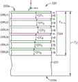
FIG. 2 is a schematic side or cross-sectional view of a single-wrap multilayer optical film configured as a reflective polarizer;
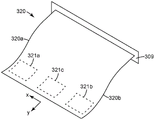
FIG. 3 is a perspective view of an optical film;
FIG. 4 is a perspective view of an optical film or laminate in relation to a Cartesian coordinate system;
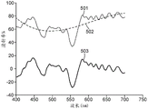
FIG. 5 is a graph of spectral transmittance used to illustrate the concept of a best-fit curve, which can be used to calculate a high-frequency spectral range rate of change parameter Δ;
FIG. 6 is a schematic perspective view of a multilayer optical film reflective polarizer disposed behind and spaced apart from an absorbing polarizer, the reflective polarizer being provided with a light diffusing layer to reduce the amount of color observed;
FIG. 7 is a schematic perspective view of a laminate of a multilayer optical film reflective polarizer and an absorbing polarizer without a light diffusing layer;
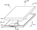
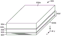
FIG. 8 is a schematic perspective view of a laminate similar to FIG. 7, but further including a glass layer from the liquid crystal panel, with an absorbing polarizer disposed between the reflective polarizer and the glass layer;
FIG. 9 is a graph of the spectral transmission of four samples of multilayer optical film reflective polarizers for normally incident light polarized along the block axis, each sample taken from the center portion of its respective film web;
FIG. 10 is a diagram similar to that of FIG. 9 for the four samples of reflective polarizers, but for normally incident light polarized along the pass axis;
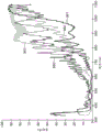
FIG. 11 is a view similar to that of FIG. 10 for the four samples of reflective polarizers, but where light is incident at a polar angle of 60 degrees in a plane including the pass axis and the normal axis, the light being p-polarized in such plane of incidence;
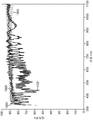
FIG. 12 is a diagram similar to that of FIG. 11 for four samples of reflective polarizer taken from the first edge portion of its respective film web, but otherwise corresponding respectively to the four samples of reflective polarizer of FIG. 11;
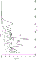
FIG. 13 is a view similar to that of FIGS. 11 and 12 for four samples of reflective polarizer taken from the second edge portion of their respective film webs, but otherwise corresponding to the four samples of reflective polarizer of FIGS. 11 and 12, respectively; and is
FIG. 14 is a graph of the spectral transmittance of one of the samples of reflective polarizers from FIG. 11 and the spectral transmittance of the sample of reflective polarizer laminated to an absorbing polarizer, in both cases for light incident at a polar angle of 60 degrees in a plane including the pass axis and the normal axis, the light being p-polarized in such plane of incidence.
In the drawings, like reference numerals designate like elements.
Detailed Description
As noted above, we have found that certain types of multilayer optical film reflective polarizers that were previously thought to have too much off-axis color can actually provide adequate performance in liquid crystal displays without the need for any air gaps or high haze light diffusing layers (and in some cases, no light diffusing layers or light diffusing structures at all) between the reflective polarizer and the rear absorbing polarizer of the LC display. Reflective polarizers of the type in question have only one set of microlayers and are oriented using a standard tenter frame such that the birefringent microlayers in the film are biaxially birefringent. Furthermore, the microlayers in the single packet have an appropriately designed layer thickness profile. Heretofore, it was believed that such reflective polarizers required a high haze light diffusing layer and were separated from the rear absorbing polarizer by an air gap to avoid undesirable color effects from the perspective of the user or viewer of the display. We have found that laminates made by combining such reflective polarizers with absorbing polarizers can be used without air gaps or any high haze light diffusing layers or structures between the polarizers, and can be used and incorporated into liquid crystal displays and the like, with sufficient color performance at both normal incidence and oblique incidence up to polar angles of at least 60 degrees.
Generally, if a multilayer optical film reflective polarizer of unspecified design is given, then proper placement of the reflective polarizer in an LC display system is a function of the color characteristics of the reflective polarizer, among others, especially at high off-axis (tilt) angles of light propagation. Such color characteristics are in turn a function of the manner in which the film is manufactured and the final physical and optical characteristics of the film.
For example, it is known to manufacture reflective polarizers by co-extruding tens, hundreds, or thousands of alternating polymer layers through a die, optionally doubling or tripling the number of layers by separating and re-stacking the flow streams in a layer multiplier device, cooling the extrudate on a casting wheel, and orienting (stretching) the cast film to reduce the film thickness such that each polymer layer forms an optically thin microlayer and induces birefringence in at least some of the microlayers. In the finished multilayer optical film, the microlayers reflect and transmit light by optical interference as a function of the refractive index difference between adjacent microlayers, the optical thickness of adjacent microlayer pairs, and the thickness profile of the stack of such layer pairs along the thickness direction or axis of the film. To make a reflective polarizer, the orientation or stretching is primarily in one in-plane direction, such that the refractive indices of the microlayers define a block axis of high reflectivity, a pass axis of low reflectivity (and high transmission), and a thickness axis perpendicular to the pass and block axes. See, for example, U.S. Pat. No. 5,882,774(Jonza et al).
Fig. 1 is provided for reference to illustrate various components, layers, and films that may be included in a typical LC display system 100. The display system 100 includes a display panel 150 and an illumination assembly 101 positioned behind the panel 150 to provide light to the panel. The display panel 150 may include any suitable type of display. In the illustrated embodiment, the display panel 150 includes or is an LC panel (hereinafter referred to as the LC panel 150). The LC panel 150 generally includes a Liquid Crystal (LC) layer 152 disposed between panels 154a,154b (collectively 154). The plates 154 are typically formed of glass and may include electrode structures and alignment layers on their inner surfaces to control the orientation of the liquid crystals in the LC layer 152. These electrode structures are typically arranged to define LC panel pixels, i.e. regions of the LC layer that can be isolated from adjacent regions to control the orientation of the liquid crystals. Color filters may also be included in one or more of the plates 152 for superimposing desired colors, such as red, green, and blue, on the sub-pixel elements of the LC layer, and thus on the image displayed by the LC panel 150.
The LC panel 150 is positioned between a front (or upper) absorbing polarizer 156 and a rear (or lower) absorbing polarizer 158. In the illustrated embodiment, the front and rear absorbing polarizers 156,158 are located outside the LC panel 150. The absorbing polarizer (156 or 158) is typically laminated to the major outer surface of its adjacent glass panel (154 a or 154b, respectively) using a suitable clear adhesive. The absorbing polarizers 156,158 in combination with the LC panel 150 control the transmission of light from the backlight 110 through the display system 100 to the viewer. For example, the absorbing polarizers 156,158 can be arranged with their pass axes (transmission axes) perpendicular to each other. For example, selective activation of different pixels of the LC layer 152 by the controller 104 causes light to be emitted from the display system 100 at specific locations as desired, thereby forming an image seen by a viewer. The controller 104 may comprise, for example, a computer or a television controller that receives and displays television images.
One or more optional layers 157 may be disposed proximate the front absorbing polarizer 156, for example, to provide mechanical and/or environmental protection to the display surface. For example, layer 157 may comprise a hardcoat over the front absorbing polarizer 156.
The illumination assembly 101 includes a backlight 110 and one or more light management films in an arrangement 140, the arrangement 140 being positioned between the backlight 110 and the LC panel 150. The backlight 110 may be or include a backlight of any known suitable design. For example, one or more light sources within the backlight may be positioned such that the backlight is an edge-lit or direct-lit backlight.
An arrangement of light management films 140 (also referred to as a light management unit) is positioned between the backlight 110 and the LC panel 150. The light management film affects the illumination light propagating from the backlight 110. In some cases, the backlight 110 can be considered to include one, some, or all of the light management films in the arrangement 140.
The arrangement 140 of light management films may include a diffuser 148. The diffuser 148 is used to scatter or diffuse light received from the backlight 110. Diffuser 148 may be any suitable diffuser film or plate. For example, the diffuser 148 may include any suitable diffusing material or materials. In some embodiments, diffuser 148 may include a polymer matrix of Polymethylmethacrylate (PMMA) having a polymer matrix including glass, polystyrene beads, and CaCO3A plurality of dispersed phases of particles. The diffuser 148 may also be or include model 3635-30, model 3635-70, and model 3635-100, model 3M available from 3M Company, St. Paul, Minnesota, USA, St., MinnesotaTM ScotchcalTMA diffusion membrane. Diffuser sheets 148 used in light management film arrangements such as arrangement 140 typically have a relatively high Haze, for example at least 40%, as measured using a Haze Gard Plus Haze meter from BYK-Gardiner, Silver Springs, MD, in maryland according to a suitable procedure such as described in ASTM D1003.
The light management unit 140 also includes a reflective polarizer 142. While reflective polarizer 142 may be of any suitable design in a general sense-for example, a multilayer optical film, a Diffusely Reflecting Polarizing Film (DRPF) such as a continuous/disperse phase polarizer, a wire grid reflective polarizer, or a cholesteric reflective polarizer-for purposes of this application, we are interested in the case where the reflective polarizer is a particular type of multilayer optical film, as discussed elsewhere herein. For example, the reflective polarizer can be a multilayer optical film of alternating polymer layers in which only one set of microlayers is present, which has been oriented using a standard tenter frame such that the birefringent layers (including the birefringent microlayers) of the film are biaxially birefringent. One of ordinary skill in the art has considered such reflective polarizers to have too much off-axis color to consider a high haze diffuser and air gaps between the reflective polarizer 142 and the rear absorbing polarizer 158 needed to keep the overall perceived color of the display system 100 at or reasonably near neutral white.
In some embodiments, a polarization control layer 144, such as a quarter-wave retarder, may be disposed between the diffuser 148 and the reflective polarizer 142. The polarization control layer 144 may be used to change the polarization of light reflected from the reflective polarizer 142 such that more of the recycled light is transmitted through the reflective polarizer 142.
The arrangement 140 of light management films may also include one or more brightness enhancing layers. A brightness enhancing layer may redirect off-axis light in a direction closer to the axis of the display. This increases the amount of light propagating on-axis through the LC layer 152, thereby increasing the brightness of the image seen by the viewer. One example of a brightness enhancing layer is a prismatic brightness enhancing layer, which has a plurality of prismatic ridges that redirect the illumination light by refraction and reflection. In FIG. 1, a first prismatic brightness enhancing layer 146a provides one-dimensional optical gain, and a second prismatic brightness enhancing layer 146b has prismatic structures oriented orthogonally to the prismatic structures of layer 146a, so that the combination of layers 146a,146b increases the optical gain of the display system 100 in two orthogonal dimensions. In some embodiments, the brightness enhancing layers 146a,146b may be positioned between the backlight 110 and the reflective polarizer 142.
The different layers in the light management unit 140 may be free standing with respect to each other. Alternatively, two or more layers in the light management unit 140 may be laminated to each other.
Two design aspects of multilayer optical film reflective polarizers for LC display systems are of particular relevance to the present application: the manner in which the extruded film is stretched-which in effect determines whether the birefringent microlayers are uniaxially birefringent or biaxially birefringent-and whether a layer multiplier device is used during manufacture, or whether the finished multilayer optical film has more than one distinct microlayer stack.
We first discuss the manner in which the extruded film is stretched or oriented. In a first known technique, a length or web of polymeric film is continuously advanced through a standard tenter apparatus. In a standard tenter frame, the film is held taut by sets of clips attached to opposite edges of the film, and the clip sets are moved forward along rails under the action of a chain drive or the like. In the section of the tenter, the straight portions of the rails are separated from each other so that the clips stretch the film in the cross-web direction (also referred to as the transverse direction) as the clips typically carry the film forward in the down-web direction (also referred to as the longitudinal direction). This orients the film primarily in the cross-web direction. Clips in a standard tenter frame maintain a constant clip pitch and move at a constant speed over the entire length of the straight track section, which prevents the film from sagging in the downweb direction. Due to this downweb constraint of the film during orientation, the stretching provided by such standard tenters is sometimes referred to as constrained stretching. As a result of the constraints, layers within a film that are birefringent under stretched conditions typically produce three different indices of refraction along the three major directions of the film (the crossweb or x direction, the downweb or y direction, and the thickness or z direction). If we denote the refractive indices of such layers as nx, ny and nz along the principal x, y and z directions, nx ≠ ny, ny ≠ nz, and nz ≠ nx. (the degree to which a material exhibits dispersion, where a given refractive index n varies to some extent as a function of optical wavelength, the refractive index may be understood as being specified at a particular visible wavelength, such as 550nm (green) or 632.8nm (helium neon laser, red), or the refractive index may be understood as being an average over the visible wavelength range, e.g. 400nm-700 nm.) it is believed that materials having such birefringence are biaxially birefringent.
In reflective polarizers in which birefringent microlayers alternate with isotropic microlayers, the difference in the interlayer refractive index along the y-direction and along the z-direction cannot be simultaneously zero as a result of the birefringent microlayers being biaxially birefringent. For p-polarized light propagating in a reference plane that includes the y-axis (i.e., the pass axis of the polarizer) and the z-axis, this in turn results in residual reflectivity and (when used in a display) perceived color for light propagating at high oblique angles relative to the optical axis perpendicular to the film.
In a second known technique, the film or web is advanced through a stretching device specifically designed to allow the web or film to relax completely in the downweb direction during the orientation process. For example, in some embodiments, the stretching device utilizes multiple sets of clips that move along a parabolic track. See, for example, U.S. Pat. No. 6,949,212(Merrill et al). By allowing the film to relax in the downweb direction (and thickness direction), layers within the film that become birefringent under stretched conditions typically produce only two different indices of refraction along three as long as the direction of the film. In other words, for such birefringent layers, the refractive index in the z-direction is equal or substantially equal to the refractive index in the y-direction, but these refractive indices are substantially different from the refractive index in the x-direction (the stretching direction). The notation nx, ny, nz is used, ny ≠ nz, but nx ≠ ny and nx ≠ nz. (in some cases, ny and nz may not be exactly equal, but their difference is very small, as described below. It is believed that materials having such birefringence are uniaxially birefringent. In reflective polarizers in which birefringent microlayers alternate with isotropic microlayers, the result of the birefringent microlayers being uniaxially birefringent is that the difference in interlayer refractive index along the y-direction and along the z-direction can be zero or substantially zero, while the difference in refractive index along the x-direction is non-zero and is large in magnitude. This results in little or no significant reflectance at high tilt angles and little or no perceived color at such angles when the film is used as a reflective polarizer in a display.
Thus, with respect to off-axis color in a display, a multilayer reflective polarizer whose birefringent microlayers are uniaxially birefringent (e.g., a polarizer made using a parabolic stretching device) has inherent advantages over a polarizer whose birefringent microlayers are biaxially birefringent (e.g., a polarizer made using a conventional tenter frame). However, in practice, all other factors being equal, the cost of manufacturing a uniaxially birefringent polarizer is higher than that of a biaxially birefringent polarizer, at least in part due to the significantly lower throughput of a dedicated parabolic stretching apparatus compared to a standard tenter frame.
The optical materials that can be used to make the reflective polarizers disclosed herein can be selected from known materials, preferably transparent polymeric materials, whose material properties allow for the co-extrusion of such materials at the same temperature and common feedblock. In an exemplary embodiment, alternating layers of thermoplastic polymers (ABABAB … …) are used, and one of the polymers is selected to be birefringent and the other polymer is selected to remain optically isotropic under stretching conditions. Suitable polymers may be judiciously selected from, for example, polyethylene naphthalate (PEN), polyethylene terephthalate (PET), polybutylene terephthalate (PBT), copolymers thereof and blends thereof. In addition, other types of polymers that exhibit birefringence and are useful for this purpose are polystyrene (including syndiotactic polystyrene), polyamides (including nylon 6), and liquid crystal polymers.
With respect to the above discussion relating to uniaxial and biaxial birefringence and the equalities and inequalities relating to nx, ny, and nz, we recognize that perfect equality between two indices of refraction may be difficult to achieve or measure, and that small differences may not be distinguishable from perfect equality from a practical standpoint. Thus, for purposes of this document, a material is considered uniaxially birefringent if one pair of refractive indices are substantially the same (e.g., if they differ by less than 0.05), while the remaining pair of refractive indices are not substantially the same (e.g., if they differ by at least 0.05). Likewise, a material is considered to be biaxially birefringent if each pair of principal refractive indices of the material are not substantially the same (e.g., if they differ by at least 0.05).
In general, in the case of multilayer optical film reflective polarizers, the biaxially birefringent layer in such polarizers can, for example, have a refractive index nx, ny, nz that satisfies the relationship | ny-nz | ≧ 0.05| and | nx-ny | >0.06 or 0.08. In contrast, a uniaxially birefringent layer in such a polarizer can, for example, have refractive indices nx, ny, nz that satisfy the relationship | ny-nz | <0.05| and | nx-ny | >0.06 or 0.08.
Another design aspect of particular relevance to the present application is the number of different stacks of microlayers present in the finished multilayer reflective polarizer, which is generally related to whether a layer multiplier device is used during the fabrication of the layers. In describing this feature, reference is now made to FIG. 2, which schematically depicts a single-wrap multilayer optical film configured as a reflective polarizer 220.
Multilayer optical film or polarizer 220 has two opposing outer major surfaces 220a,220b between which are multiple different polymer layers. Polymeric materials and film making equipment useful for making such films by coextrusion and stretching are known, see, for example, U.S. Pat. Nos. 5,882,774(Jonza et al) and 6,783,349(Neavin et al) and patent application publication US 2011/0102891(Derks et al). Adjacent polymer layers have substantially different refractive indices along at least one of the principal x, y or z axes such that some light (depending on the direction of propagation and polarization state of the light) is reflected at the interface between the layers. Some of the polymer layers of polarizer 220 are sufficiently thin ("optically thin") such that light reflected at multiple interfaces undergoes constructive or destructive interference in order to impart desired reflective or transmissive properties to the multilayer optical film. These layers are referred to herein as microlayers and are labeled "a" and "B" in fig. 2. For reflective polarizers designed to reflect visible light, each microlayer typically has an optical thickness (i.e., the physical thickness times its refractive index) of less than about 1 micron. As is known in the art, thicker layers, such as a skin layer or a protective interface layer (PBL), may also be present in the polarizer, as shown by layer 222 in fig. 2. Such "optically thick" layers have an optical thickness of at least 1 micron, and typically much greater than 1 micron, and are not considered microlayers. (throughout this document, thickness refers to physical thickness when the term "thickness" is used without the modifier "optical", unless the context indicates otherwise)
Cohesive groupings of microlayers are referred to herein as packets or microlayers of a microlayer. As shown, polarizer 220 includes only one set of microlayers 224. As shown, the bag 224 has a (physical) thickness T1And polarizer 220 has a total thickness T2. Constructing a multilayer optical film with only one set of microlayers 224 simplifies the manufacturing process (assuming that the number of microlayers required is not excessive) and allows for better control of the thickness and thickness distribution of the microlayers, which in turn allows for better control of the spectral reflectance and spectral transmission characteristics of the reflective polarizer. In fig. 2, pairs of adjacent microlayers form Optical Repeat Units (ORUs), labeled ORU1 through ORU6, each ORU having light equal to the sum of the optical thicknesses of its constituent microlayersOptical thickness (OT1, OT2 … … OT 6). Although only 6 ORUs (12 microlayers) are shown, the reader should appreciate that a typical single-package reflective polarizer will include many more microlayers and ORUs to provide sufficient reflectivity across the visible spectrum. For example, the total number of microlayers in a single-package reflective polarizer may be less than 500, or less than 400, or less than 350, or in the range from 200 to 500, or in the range from 200 to 400, or in the range from 200 to 350, or in the range from 225 to 325. The optical thickness of the ORU determines the wavelength at which the ORU exhibits peak reflectivity. The thickness of the ORUs is carefully controlled according to the desired layer thickness profile, with the optical thickness of the ORUs increasing gradually from one side of the packet (e.g., near major surface 220a) to the opposite side of the packet (e.g., near thick layer 222), allowing the microlayers to provide broad reflectivity across the visible spectrum and over a desired range of viewing angles, as long as a sufficient number of ORUs are present in the packet.
To more easily achieve the desired optical performance goals, another approach is to design a multilayer optical film reflective polarizer to have more microlayers than can actually be incorporated into a single envelope. For this reason (or for other reasons), reflective polarizers are fabricated in which a microlayer is divided or separated into two or more distinguishable microlayers, with at least one optically thick polymeric material separating adjacent packets. Such multi-wrap reflective polarizers can be manufactured in various ways. For example, rather than using only one feedblock to make a reflective polarizer, multiple feedblocks (corresponding to multiple packets) may be used and the packets from the feedblocks combined while the polymer material is still liquid. See, for example, patent application publication US 2011/272849(Neavin et al). Alternatively, the reflective polarizer may be fabricated using a layer multiplier device, for example, as discussed in U.S. Pat. No. 5,882,774(Jonza et al) or U.S. Pat. No. 6,025,897(Weber et al). The layer multiplier device may, for example, double or triple the number of microlayers and ORUs, resulting in double or triple the number of packets (respectively) in the finished reflective polarizer. In yet another approach, a multi-wrap reflective polarizer may be fabricated by laminating two or more multilayer optical film reflective polarizers together, each made of, for example, a single feedblock.
Disadvantages of multi-wrap reflective polarizers tend to include: (a) increased manufacturing costs due to the large number of layers, and resulting high material costs, and (b) relatively large overall physical thickness, which can be a significant disadvantage in some display applications. (the disclosed reflective polarizers advantageously have a thickness of less than 50 microns, or less than 40 microns, or in the range from 25 microns to 50 microns, or from 25 microns to 40 microns.) however, even when such polarizers are oriented using standard tenter frames, that is, even when the birefringent microlayers in such reflective polarizers are biaxially birefringent, the greater number of microlayers enables the multi-wrap reflective polarizer to achieve display quality optical performance goals. This is because, as described in patent application publication US 2013/0063818(Weber et al), multiple packets can produce spectral smoothing, resulting in a reduced amount of off-axis color. Single-wrapped reflective polarizers do not take advantage of this spectral smoothing technique and have a small margin of error with respect to the rate of change of layer thickness.
When discussing multilayer optical films made by co-extruding multiple layers of alternating polymeric materials through feedblock/dies and orienting the films by stretching operations, and the suitability of such films for visual display applications, one aspect of the films of practical interest to one of ordinary skill is the degree of spatial uniformity of the films produced. This aspect of the membrane is of concern because it relates to how much of the manufactured membrane can be used in the intended application, rather than how much of the membrane must be handled. This in turn can affect manufacturing yield and cost, and it can also impose limitations on the size of how large sheets are to be obtained or cut from a given film sheet to fit in a large display system. In the case of optical films used in LC displays, a high degree of spatial uniformity is desired so that film-related artifacts are not noticeable in the displayed image.
The optical film 320 is schematically shown in fig. 3. The film 320 is manufactured on a film line and fed from a tenter frame or other stretching apparatus, schematically illustrated as element 309. The film 320 has a longitudinal or down-web direction parallel to the y-axis, as shown. The film 320 also has a transverse or cross-web direction parallel to the x-axis, as shown. Two opposing longitudinal edges 320a,320b define the longitudinal boundaries of the film 320. Near these edges are sets of clips from a tenter frame or special stretching equipment that grip the film during the previous orientation step, after which the film 320 is trimmed to the edges 320a,320 b. Three film samples intended for use as reflective polarizers in display applications or other desired applications are shown in the figure: film sample 321a near film edge 320a, film sample 321b near film edge 320b, and film sample 321c located in the central portion (with respect to the transverse direction) of film 320. These film samples or sheets are cut from a larger web or film 320 using a knife, cutter, or other suitable cutting tool. As reflective polarizers, the optical film 320 and each film sample 321a,321b,321c has a block axis parallel to the x-axis and a pass axis parallel to the y-axis.
Ideally, the film samples 321a,321b,321c would all have the same optical characteristics and performance. In practice, however, the film 320 exhibits a certain amount of spatial rate of change. As a result, the layer thickness profile of the microlayers near the edges of the film 320 (and their corresponding spectral transmission and reflection characteristics) is slightly different from the layer thickness profile of the central portion of the film (and corresponding spectral transmission and reflection characteristics). The amount of spectral feature variation between the center and edges of the film is particularly significant for the types of multilayer optical films of interest in this application, i.e., reflective polarizers having only one set of microlayers and oriented using a standard tenter such that the birefringent microlayers in the film are biaxially birefringent. Significant spatial variation helps others believe that these films will not be suitable for on-glass construction as described above.
Elsewhere in this document, we discuss optical properties such as transmission and reflection at specific angles and polarization states for certain polarizing films and laminates. Fig. 4 is intended to assist the reader in understanding the relative directions, planes and angles. In this figure, optical body 412 is shown in the context of a cartesian x-y-z coordinate system, which may be or include, for example, a multilayer optical film configured as a reflective polarizer or such film laminated to an absorbing polarizer and/or another optical film or body. As a polarizer, the optical body 412 has a transmission axis 413 and a blocking axis 414 corresponding to the y-axis and the x-axis perpendicular to each other, respectively. The z-axis corresponds to the thickness direction of the body 412, i.e., an axis perpendicular to the plane of the body 412. Light that is normally incident on the body 412 propagates parallel to the z-axis. Such light is substantially transmitted by the body 412 if it has a linear polarization component parallel to the pass axis 413, and substantially blocked (reflected in the case of a reflective polarizer and absorbed in the case of an absorbing polarizer) if it has a linear polarization component parallel to the block axis 414.
In the absence of alternative terminology, "plane of incidence" is used herein to refer to a reference plane containing the surface normal and the direction of light propagation, which includes both the case where light is incident on the film and the case where light is not incident on the film but exits the film. Likewise, "angle of incidence" is used to refer to the angle between the normal to the surface and the direction of light propagation, and includes both the case where light is incident on the film and the case where light exits the film.
Two reference planes of incidence 416 and 418 are included in the figure: the reference plane 416 contains the block axis 414 and the z-axis; and reference plane 418 includes a transmission axis 413 and a z-axis. Two obliquely incident rays 415,417 are shown in the figure. Ray 415 lies in plane 416 and ray 417 lies in plane 418. The light rays 415,417 are obliquely incident because their propagation directions each form a non-zero polar angle θ with respect to the z-axis. For each ray 415,417, the polarization state of the ray can be decomposed into two orthogonal components, represented in the figure as a pair of orthogonal double-headed arrows: the component whose polarization state is in the plane of incidence is called "p-polarization", and the component whose polarization state is perpendicular to the plane of incidence is called "s-polarization". As can be seen by observing this figure, the polarization direction of the p-polarized light of oblique ray 415 is different (and not parallel) to the polarization direction of the p-polarized light of oblique ray 417. The polarization direction of the s-polarized light of oblique light ray 415 is different (and not parallel) to the polarization direction of the s-polarized light of oblique light ray 417. It will also be apparent that the p-polarized component of the light ray 415 is perpendicular to the pass axis 413 and is partially aligned with the block axis 414, while the s-polarized component of the light ray 415 is parallel to the pass axis 413. The p-polarized component of the light ray 417 is perpendicular to the block axis 414 and is partially aligned with the pass axis 413, while the s-polarized component of the light ray 417 is parallel to the block axis 414. It follows that depending on the direction of incidence, the p-polarized light may be perpendicular to the pass axis in some cases and perpendicular to the block axis in other cases; the s-polarized light may be parallel to the pass axis in some cases and parallel to the block axis in other cases.
One method of quantifying the color associated with a given transmission (or reflection) spectrum involves calculating the high frequency spectral rate of change of the spectrum over a range of visible wavelengths. We refer to the calculated high frequency spectral rate of change as Δ, the greek letter δ. A curve useful for illustrating this method is shown in the transmission versus wavelength graph of fig. 5. In the graph, curve 501 is an arbitrary plot of transmittance versus wavelength for a given polarizer under a given illumination geometry. Curve 501 shows some rate of change in the visible wavelength range, which we can assume extends from 400nm to 700nm, but other reasonable endpoint wavelengths can be used. When the film is illuminated with white light, the rate of change of curve 501 appears to a user or viewer as a colored (non-white) appearance. Of particular interest is any color due to the relatively high frequency rate of change as a function of wavelength. For example, a spectral rate of change having a period of about 20nm or less may result in a rapidly changing observed color in space and angle.
To quantify the high frequency rate of change Δ, and thus the color associated with such rate of change, we first define a smoothed spectrum for comparison curve 501. The smoothed spectrum should be a best fit curve to the curve 501, such as a best fit curve in the least squares or weighted least squares sense, and the smoothed spectrum should be a low order polynomial, so that only higher orders-corresponding to higher frequencies of change are included in the comparison. Preferably, the smoothed spectrum is a third order best fit curve of wavelengths, i.e., a third order polynomial as follows:
a0+a1λ+a2λ2+a3λ3,
wherein the coefficient a is selected according to the least square method0、a1、a2And a3. Calculate such for curve 501The best fit third order spectrum results in curve 502. The actual transmittance (curve 501) can then be compared to the best fit spectrum (curve 502) by subtracting curve 502 from curve 501, resulting in comparison curve 503. Note that the comparison curve 503 has no physical significance when it contains negative transmittance values. However, curve 503 may be used to derive a physically meaningful value for the high frequency rate of change element of curve 501. To this end, we calculate the statistical standard deviation of the comparison curve 503 over the same visible spectrum (e.g., from 400nm to 700 nm). For curve 503 shown in fig. 5, this standard deviation is equal to 9.18% or 0.0918. Thus, the high frequency change Δ of curve 501 may be said to be 9.18% or 0.0918. The high frequency rate of change is in the same units as curves 501,502 and 503. Thus, if the units of the curve 501, etc. are given in percent transmission (0% minimum, 100% maximum), then the units of high frequency rate of change are also percent transmission or percentages. However, if the units of the curve 501, etc. are given only in transmission (minimum 0.0, maximum 1.0), then the unit Δ of the high frequency rate of change is also only in transmission, with no percentile.
Turning now to fig. 6, we see selected elements of a schematically illustrated LC display system 600 therein. The selected elements shown are a rear absorbing polarizer 658 (which may be the same as or similar to rear absorbing polarizer 158 in FIG. 1), a multilayer optical film reflective polarizer 620 (which may be the same as or similar to reflective polarizer 142 of FIG. 1 or reflective polarizer 220 of FIG. 2), and a light diffusing layer 625 disposed on the front major surface of reflective polarizer 620. Other components included in the LC display system, such as the LC panel, the front absorbing polarizer, and the backlight, have been omitted from the figure for simplicity. The optical film is generally located in or parallel to the x-y plane. A first user or viewer 608 is positioned in front of the system 600 and views the display at a normal angle of incidence along the system optical axis parallel to the z-axis. A second user or viewer 609 is also located in front of the system 600, but views the display at an oblique angle.
The rear absorbing polarizer 658 is assumed to be any absorbing polarizer known in the art as it is suitable for use in LC displays. The polarizer 658 has a pass axis and a block axis (not shown in FIG. 6), the polarizer being oriented such that the pass axis is parallel to the y-axis and the block axis is parallel to the x-axis.
As already mentioned, we have found through investigation and testing that, contrary to the general opinion, single-wrap biaxial birefringent reflective polarizers can provide acceptable optical performance in a on-glass construction, i.e., when laminated to a rear absorbing polarizer (without a diffusing layer or structure therebetween, but in some cases may include such layers or structures having relatively low haze, e.g., less than 30%, or less than 20%, or less than 10% haze). Two examples of on-glass constructions are shown in fig. 7 and 8.
In the schematic of fig. 7, a laminate 730 or optical body is shown in which a multilayer optical film reflective polarizer 720 is attached to a rear absorbing polarizer 758 by a transparent adhesive layer 726. The reflective polarizer 720, the rear absorbing polarizer 758, and the adhesive layer 726 are all coextensive with each other, and there is no air gap between the reflective polarizer 720 and the absorbing polarizer 758. The viewer side of the laminate 730 is in the positive z-direction, so the rear absorbing polarizer 758 may be considered in front of the reflective polarizer 720. The reflective polarizer 720 may be the same as or similar to the reflective polarizer 620 described above. Thus, the reflective polarizer 720 is a single-wrap multilayer optical film made by coextrusion of alternating polymer layers, the film with birefringent microlayers being biaxially birefringent because the polarizer 720 has been constrained stretched on a conventional tenter. The reflective polarizer 720 can be the central portion of the reflective polarizer web, see, e.g., film sample 321c in FIG. 3, or it can be the edge portion, see, e.g., film samples 321a,321 b.
The reflective polarizer 720 has a pass axis 713a that is substantially parallel to the y-axis and a block axis 714a that is substantially parallel to the x-axis. The number of ORUs in a single microlayer, and the thickness distribution of these ORUs, provides reflective polarizer 720 with high transmission for normally incident visible light polarized parallel to pass axis 713a, and low transmission (and high reflectivity) for normally incident visible light polarized parallel to block axis 714a (since transmission + reflectivity equals approximately 100% for these low absorption multilayer optical films). For example, the transmission of normally incident visible light polarized parallel to the pass axis 713a can be at least 60%, or at least 70%, or at least 80% when averaged over the visible wavelength range, and the transmission of normally incident visible light polarized parallel to the block axis 714a can be less than 30%, or less than 20%, or less than 10% when averaged over the visible wavelength range. The optical performance of the reflective polarizer 720 of oblique p-polarized light incident in the reference plane containing the z-axis and the pass axis 713a is affected by the inevitable interlayer refractive index mismatch resulting from the biaxial birefringent properties of the birefringent microlayers in the film. For such oblique light at a polar angle of incidence of 60 degrees, the transmittance value of reflective polarizer 720 at least some wavelengths from 450nm to 700nm is in a range from 70% to 90% or from 70% to 85%; in some cases, the transmittance of such oblique light may be less than 90% over a wavelength range from 400nm to 500 nm.
The total thickness of the reflective polarizer 720 may be less than 50 microns or less than 40 microns, or it may be in the range from 20 microns to 50 microns, or in the range from 20 microns to 40 microns, or in the range from 25 microns to 40 microns. The layer thickness profile of the ORUs in the microlayers of polarizer 720 can be designed such that for 60 degree p-polarized oblique light, the high frequency spectral rate of change Δ of the transmittance of the polarizer is less than 0.08 (i.e., less than 8%) or less than 0.05 (i.e., less than 5%), as calculated over a wavelength range from 400nm to 700nm relative to a best fit curve with a third order polynomial of wavelength.
The rear absorbing polarizer 758 having the pass axis 713b and the block axis 714b may be the same as or similar to the rear absorbing polarizer 658 described above. The absorbing polarizer 758 is oriented relative to the reflective polarizer 720 such that the pass axes 713a,713b are substantially aligned and the block axes 714a,714b are also substantially aligned. For example, two such substantially aligned axes may be characterized by an angular deviation of less than 1 degree or less than 0.1 degrees.
The laminate 730 may consist of (only of) or may consist essentially of the reflective polarizer 720, the absorbing polarizer 758, and the adhesive layer 726. In some embodiments, the laminate 730 and each of the three components do not include any significant identifiable light diffusing layer or light diffusing structure, such as beads or other particles having different indices of refraction, or textured or other non-smooth major surfaces. Accordingly, the laminate 730 may not have any such light diffusing layer or light diffusing structure. However, where the laminate 730 does include such a diffusing layer or structure, it is generally desirable to at least ensure that no such diffusing layer or structure is disposed between the reflective polarizer 720 and the absorbing polarizer 758. The foregoing statements were made in recognition that even ideal flat optical films and layers with excellent optical clarity may exhibit a small but measurable amount of light scattering or diffusion. Thus, for the sake of clarity, we can establish a minimum threshold below which the layer or structure in question can be considered, from a practical point of view and for the purposes of this document, to be free of light diffusion. We set this minimum light diffusion threshold to a Haze value of 5%, or 4%, or 3%, or 2%, or 1% according to a suitable procedure as described in ASTM D1003, as measured using a Haze Guard Plus Haze meter from BYK-Gardiner, Silver Springs, MD, ag quan, ma.
Optical films are typically sold and/or shipped with temporary polymeric release liners on both sides to protect the major surfaces of the film from scratches or other damage. Such release liners are easily removed from the product by peeling. The release liner may contain dyes, pigments, or other agents, including light diffusing agents, so that the release liner can be easily seen or detected by a user. Such temporary release liners may also be applied on the outer surface of the laminate 730. However, such release liners may be distinguished from the laminate 730 and need not be considered part thereof. Thus, to the extent that such release liners are present on the laminate 730 (or on other laminates disclosed herein, including the underlying laminate 830) and have significant light diffusing properties, it can still be said correctly that the laminate does not include any significant light diffusing layer or structure.
However, the reader should note that in some cases it may be desirable to include one or more intermediate diffusing layers or structures between reflective polarizer 720 and absorbing polarizer 758, such intermediate diffusing layers or having a significant amount of haze, i.e., greater than the minimum light diffusion threshold described above, but less than the high haze diffusers typically present in isolated constructions (e.g., the construction of fig. 6). For example, a diffusive reflective layer or structure may be included between the reflective polarizer 720 and the absorbing polarizer 758 that has a relatively low haze, e.g., less than 30%, or less than 20%, or less than 10% haze.
The layer thickness profiles used in the disclosed biaxial birefringent reflective polarizers demonstrate some additional teachings. As already mentioned, the microlayers in the microlayers are organized into Optical Repeat Units (ORUs), and the optical thickness of the ORUs (and microlayers) is designed to provide high broadband reflectivity of light of block light polarization and high broadband transmissivity (low reflectivity) of light of pass light polarization for light across the visible spectrum, over a desired range of angles and directions of incidence. This is typically accomplished by adjusting the thickness profile of the ORUs along the thickness direction (z-axis) of the film to be a monotonic or nearly monotonic function, with thinner ORUs typically located on one side of the bag (referred to herein as the thin side) and thicker ORUs typically located on the opposite side of the bag (referred to herein as the thick side). To reduce the undesirable perceived off-axis transmitted color of the disclosed films, it may be useful in at least some embodiments to (a) orient the reflective polarizer so that the thick side of the microlayers faces the viewer (either the absorbing polarizer or the LC panel), and the thin side of the microlayers faces the backlight, and (b) the ORU thickness profile is adjusted to vary smoothly, so that, for highly oblique incident light of the pass polarization state, the spectral transmission of the film also varies smoothly within the visible spectrum, and (c) adjusting the ORUs thickness profile in such a way as to avoid an excessive number of ORUs at the thick end of the packet exceeding the point at which the ORUs has a resonant reflectance peak at 650nm at an oblique limiting angle, although such adjustment may produce a rate of change in the reflective polarizer transmission spectrum of light in the pass polarization state incident at or near the oblique limiting angle.
Another laminate 830 or optical body is shown in fig. 8. The laminate 830 may be the same or similar to the laminate 730 described above, except that two additional layers are added. Accordingly, laminate 830 includes a rear absorbing polarizer 858, a multilayer optical film reflective polarizer 820, and an adhesive layer 826 that bonds absorbing polarizer 858 to reflective polarizer 820. These elements may be the same as or similar to the corresponding elements of laminate 730, and they form an optical body or structure 830', which may thus be the same as or similar to laminate 730, except that the front of structure 830' is attached to other layers. In particular, the front major surface of rear reflective polarizer 858 is bonded to glass layer 854 by adhesive layer 828. Adhesive layer 828 may be the same or similar to adhesive layer 826. The glass layer may be the back or rear panel of a liquid crystal panel, such as panel 154b of LC panel 150, as described above.
Example (b):
several reflective polarizers and laminates using such polarizers were prepared and tested. All reflective polarizers are made by coextruding multiple layers of two alternating polymeric materials using feedblocks and dies, and then orienting the films using a stretching operation to form a multilayer optical film reflective polarizer. For each film, one of the polymeric materials becomes birefringent under stretched conditions, while the other polymeric material remains substantially isotropic.
In short, one of the reflective polarizers, "example 1," is fabricated without the use of a layer multiplier device, and has only one set of microlayers. In addition, the example 1 polarizer was oriented using a standard tenter frame such that the birefringent microlayers in the film were biaxially birefringent. The other reflective polarizer, comparative example 1, was similar in design and construction to the example 1 polarizer, but the layer thickness profile of the ORU in the microlayers was less controlled than the example 1 polarizer, and therefore the rate of change of spectral transmission over the visible wavelength of the spectrum was greater. Another reflective polarizer, comparative example 2, was prepared using a layer multiplier device that can form three different microlayers in the film. Similar to example 1 and comparative example 1, the comparative example 2 polarizer was oriented using a standard tenter frame to form a biaxially birefringent microlayer. Another reflective polarizer, comparative example 3, was made from only one set of microlayers, but was oriented using a parabolic stretching device to form uniaxially birefringent microlayers. Samples of these reflective polarizers were obtained from the center and edge portions of their respective films, as described below. The reflective polarizers of example 1, comparative example 2, and comparative example 3 represent reflective polarizer products that have been sold in the united states for more than one year. However, applicants are unaware that example 1 reflective polarizers were once sold or used in a structured on glass form (e.g., in a laminate with an absorbing polarizer).
Example 1.
In the two alternating polymeric materials used to make the polarizer of example 1, the birefringent polymer was a copolyester of 90 mole% naphthalate and 10 mole% dimethyl terephthalate (referred to herein as 90/10coPEN), where 100% of the diol was ethylene glycol. The isotropic polymer was a blend of 58 wt% PETg GN071 (available from Eastman Chemical Company, Kingsport, TN) and 42 wt% 90/10 coPEN. The copolymer has an isotropic refractive index of about 1.593 for 633nm light. The two polymer materials were coextruded using 275 layer feedblocks and film making equipment similar to that described in U.S. patent 6,783,349(Neavin et al) except that no layer multiplier equipment was used. The layer thickness profile of 275 layers (about 137 ORUs) was controlled to substantially match the target monotonic optical thickness profile using a spindle heater positioned within the feed block, and the temperature profile of the heater was dynamically adjusted along its length during coextrusion to make the target layer thickness profile almost error free. The final polarizing film, referred to herein as the example 1 polarizer, included optically thick skin layers of PETg GN071 forming the outermost layer of the film exposed to air on the front and back of the microlayers. The example 1 polarizer was oriented in a standard tenter frame as described above at a transverse stretch ratio of about 6:1 and a machine direction (machine direction) stretch ratio of 1:1, and at a rate of about 60%/second. For such films, the temperature of the preheat zone (in which the film is heated prior to substantial stretching) is 312 ° f, the temperature of the stretch zone (in which the film is stretched) is 287 ° f, and the temperature of the heat-set zone (in which the film remains held by the tenter clips after the stretch zone) is 290 ° f. In the heat-set zone, the film relaxed 0.3% in the cross direction with no change in machine direction length.
The polarizer of example 1 had a finished film thickness of about 30 microns, with each outer skin layer having a thickness of about 1 micron.
Comparative example 1.
Comparative example 1a polarizer was prepared in the same manner as the polarizer of example 1, except that: (a) the isotropic polymer was PETg GN071 material described above (which had a refractive index of 1.563 for 633nm light, lower than the isotropic polymer of example 1) and (b) the temperature profile of the spindle heater was not adjusted in the same way as in example 1. This resulted in a layer thickness profile of 275 layers (approximately 137 ORUs) that was not optimized to substantially match the target monotonic optical thickness profile of example 1, which in turn resulted in a more highly variable transmission spectrum and a more colorful appearance at oblique angles. Comparative example 1 the polarizing film was oriented in a standard tenter frame at about 6:1 in the transverse direction and about 1:1 in the machine direction (machine direction).
The polarizer of comparative example 1 had a finished film thickness of about 32 microns, with each outer skin layer having a thickness of about 1 micron.
Comparative example 2.
Of the two alternating polymeric materials used to make the polarizer of comparative example 2, the birefringent polymer was polyethylene naphthalate (PEN). The isotropic polymer was a copolyester consisting of 55 mole% naphthalate and 45 mole% dimethyl terephthalate (referred to herein as coPEN 55/45HD) wherein 96 mole% of the diol was ethylene glycol and 8 mole% of the diol was hexylene glycol. The two polymer materials were coextruded into an alternating layer arrangement with a total of 275 layers and the extrudate was fed into a 3:1 layer multiplier device that splits the extrudate and laminates three extrudate components (packs) onto each other. The layer thickness profile of each packet is managed by using a shaft heater system to avoid an excessive number of microlayers or ORUs at a particular thickness, thereby avoiding having a reflectivity peak for any particular wavelength. The resulting cast web was further processed and stretched in a standard tenter frame to a transverse direction stretch ratio of about 6:1 and a machine direction (machine direction) stretch ratio of 1: 1. This produced a reflective polarizing film having about 825 total microlayers, split into three different microlayers each having 275 microlayers (about 137 ORUs) with an optically thick Protective Boundary Layer (PBL) therebetween as described above, and an optically thick skin layer of PETg GN071 material at the outer major surface.
The polarizer of comparative example 2 had a finished film thickness of about 94 microns, with each outer skin layer having a thickness of about 7 microns and each PBL having a thickness of about 4 microns.
Comparative example 3.
Of the two alternating polymer materials used to make the polarizer of comparative example 3, the birefringent polymer was 90/10 coPEN. The isotropic polymer is a copolymer consisting of 85 wt% Xylex EXXX0282 available from sauter basic industries (SABIC) located in sauter Arabia (Riyadh, Saudi Arabia) and 15 wt% PETg GN071 available from Eastman Chemical Co. The two polymeric materials were coextruded in an alternating layer arrangement, 275 layers total, into 275 microlayers (about 137 ORUs) in a single package film. The layer thickness profile of the 275 layers was controlled using a spindle heater positioned within the feed block to substantially match the target monotonic optical thickness profile, and the temperature profile of the heater was dynamically adjusted along its length during coextrusion to provide a target layer thickness profile with little error. The cast web was further processed and stretched with a parabolic stretching apparatus at a transverse stretch ratio of about 6:1 and a machine direction (machine direction) stretch ratio of about 0.5:1 (i.e., 1/2 reduced to its length in the machine direction) to produce a finished reflective polarizing film having 275 total microlayers arranged into individual microlayers having optically thick skin layers at the outer major surface, as described in U.S. patent 6,949,212(Merrill et al). As described in the' 212Merrill et al patent, for these multilayer materials and this type of deformation, there is a close match of refractive indices in the y and z directions between adjacent birefringent and isotropic microlayers, and thus the reflectivity produced by the multilayer stack is small for p-polarized transmitted state light at any angle of incidence.
Samples of these four reflective polarizing films were then taken from different locations on their respective film webs, for example, as set forth in fig. 3, and tested. Fig. 9 to 14 show some test results.
FIG. 9 shows the measured transmission of normally incident light polarized parallel to the block axis of each sample of reflective polarizer. These measurements were for a sample of reflective polarizing film taken from the central portion of each respective film web. Curve 900 is the measured transmission of a sample of the reflective polarizer of example 1. Curves 901,902 and 903 are the measured transmission of samples of the reflective polarizers of comparative example 1, comparative example 2 and comparative example 3, respectively.
FIG. 10 is a graph similar to that of FIG. 9 for the same four samples of reflective polarizers, but for normally incident light polarized parallel to the pass axis of each such polarizer. Thus, curve 1000 is the measured transmittance of the sample of example 1, and curves 1001,1002, and 1003 are the measured transmittances of the samples of comparative example 1, comparative example 2, and comparative example 3, respectively.
The polarizing film was also evaluated by visual observation at normal incidence. Each of the four reflective polarizer samples from fig. 9 and 10 was viewed at normal incidence (taken from the central portion of the respective film web) using white light illumination, and each of these polarizer samples exhibited little or no color in transmission. That is, when a given polarizer sample is placed between a white light source and the eye of an observer, the polarizer sample does not substantially change the white appearance of the light source at normal incidence. This was also found to be true for samples of the reflective polarizer of example 1, the reflective polarizer of comparative example 2, and the reflective polarizer of comparative example 3 taken from the edge portions of each respective film web.
A more difficult test for a reflective polarizer in terms of its perceived color is the appearance of the reflective polarizer at significant oblique angles. At oblique viewing angles, any refractive index difference between the microlayers in the thickness direction (z-direction) becomes significant, and a shift of the transmission spectrum to shorter wavelengths also occurs. Fig. 11, 12 and 13 show transmission spectra of various samples of four tested reflective polarizers measured under the following observation or illumination geometry: the spectral transmittance of each sample was tested for light in the plane of incidence (reference plane) containing the z-axis and y-axis (transmission axis) of the film, which was polarized (i.e., p-polarized) within that plane of incidence, at a polar angle of 60 degrees. (furthermore, in each case, the tested films were oriented such that the thick side of their microlayers faced the light source of the spectrophotometer.) with this geometry, the fresnel reflection at the polymer/air interface outside the film was small or negligible.
Fig. 11 shows the 60 degree p-polarization transmission spectra as described above for each of the reflective polarizing film samples used in fig. 9 and 10, i.e., film samples taken from the central portion of the respective film webs (see, e.g., film sample 321c in fig. 3). Thus, curve 1100 is for such a sample of the reflective polarizer from embodiment 1, curve 1101 is for such a sample of the reflective polarizer from comparative example 1, curve 1102 is for such a sample of the reflective polarizer from comparative example 2, and curve 1103 is for such a sample of the reflective polarizer from comparative example 3.
The sample of comparative example 3 (curve 1103) shows a very high transmission with little variation due to the interlayer refractive index matching in both the y-and z-directions (achieved by uniaxially birefringent microlayers) and well controlled layer thickness profile. The sample of example 1 (curve 1100) and the sample of comparative example 2 (curve 1102) showed lower transmission throughout the visible region, which can be explained by the use of a standard tenter frame in the manufacture of these films, resulting in biaxial birefringence and a significant difference in the z-direction of the interlayer refractive index. However, the relatively small spectral changes of curves 1100 and 1102 indicate that the microlayers and ORUs in the microlayers of these samples have good layer thickness control and well-tailored layer thickness profiles. The sample of comparative example 1 (curve 1101) had a lower average transmission than the other samples due to the lower index isotropic polymer used in the film, but in addition to this, the curve 1101 had a large rate of change in the visible wavelength region, indicating a high perceived color.
High frequency rate values Δ of the curves 1100 to 1103 are calculated, wherein a cubic polynomial is used in each case as a best-fit curve, and wherein the calculation is carried out in the wavelength range from 400nm to 700 nm. The results are as follows: Δ for curves 1100, 1101, 1102 and 1103 are 0.0118, 0.0515, 0.0216 and 0.0043, respectively. These results are consistent with visual observation of the film samples at 60 degree geometry: the sample of comparative example 3 exhibited the least amount of color, and the samples of example 1 and comparative example 2 exhibited more color than comparative example 3, but still had a certain amount of color that was acceptable in some display applications, while comparative example 1 exhibited the most color. Note that the sample of example 1 (curve 1100) had a Δ of less than 0.08, and less than 0.05, but at least 0.01.
To investigate the effect of spatial variation at different regions of the film web, measurements were also made on samples of the reflective polarizer taken from the edges of the respective film webs.
Fig. 12 is a graph of spectral transmittance measured under the same measurement conditions as fig. 11, but in fig. 12, film samples are taken from the first edge portions of the respective film webs, see, e.g., film sample 321a in fig. 3. Thus, curve 1200 is for such a sample of the reflective polarizer from embodiment 1, curve 1201 is for such a sample of the reflective polarizer from comparative example 1, curve 1202 is for such a sample of the reflective polarizer from comparative example 2, and curve 1203 is for such a sample of the reflective polarizer from comparative example 3.
Fig. 13 is a graph of spectral transmittance measured under the same measurement conditions as fig. 11 and 12, but in fig. 13 film samples are taken from the second edge portion of the respective film web, see, e.g., film sample 321b in fig. 3. Thus, curve 1300 is for such a sample of the reflective polarizer from embodiment 1, curve 1301 is for such a sample of the reflective polarizer from comparative example 1, curve 1302 is for such a sample of the reflective polarizer from comparative example 2, and curve 1303 is for such a sample of the reflective polarizer from comparative example 3.
The graphs of fig. 12 and 13 follow a trend similar to that of fig. 11. Thus, comparative example 3 still exhibited the highest and smoothest transmission over the visible wavelength range for the samples taken from the edges of the film web. Comparative example 1 still exhibited the lowest average transmittance and the greatest rate of spectral change, and thus exhibited color. And example 1 and comparative example 2 still showed intermediate transmittance, which was greater in the rate of spectral change in the visible region than comparative example 3, but less than comparative example 1.
The high frequency rate of change Δ for the curves in fig. 12 and 13 is calculated in the same manner as described above in connection with fig. 11. The results are as follows: Δ for curves 1200, 1201, 1202, and 1203 are 0.0383, 0.0918, 0.0421, and 0.0049, respectively, and Δ for curves 1300, 1301, 1302, and 1303 are 0.0516, 0.0607, 0.0339, and 0.0059, respectively. These results are consistent with visual observations of these near-edge film samples at 60 degree geometry: the sample of comparative example 3 exhibited the least amount of color, and the samples of example 1 and comparative example 2 exhibited more color than comparative example 3, but still had a certain amount of color that was acceptable in some display applications, while comparative example 1 exhibited the most color.
Laminates of various reflective polarizing films are also made by bonding a reflective polarizer to an absorbing polarizer using a transparent optical adhesive layer, for example, as schematically shown in fig. 7. The absorbing polarizer was HL C2-5618S from Sanritz (Tokyo, Japan). The optical adhesive was provided with an HL C2-5618S polarizer from Sanritz. There is no air gap between the absorbing polarizer and the reflecting polarizer, and the polarizers are oriented such that their pass axes are substantially aligned, and such that their block axes are also substantially aligned. No light diffusing layer or structure is disposed between the reflective polarizer and the absorbing polarizer, and no light diffusing layer is included at all in the laminate. Such laminates were made with samples of the reflective polarizer taken from the center portion of the reflective polarizer web and samples taken from the edge portions of the web.
In these laminates, the absorbing polarizer has relatively little effect on the transmission spectrum observed through the reflective polarizer itself, and on the rate of change of such spectrum. This is shown in fig. 14. In the figure, a curve 1401 is the transmission spectrum of a sample of the comparative example 1 reflective polarizer taken from the central portion of the film web for p-polarized light incident at a polar angle of 60 degrees in a plane including the z-axis and the y-axis (transmission axis). A laminate as described in the previous paragraph is manufactured using such a reflective polarizer and an absorbing polarizer. The transmission spectrum of such a laminate was measured and is shown as curve 1401 a.
Visual inspection of the various laminates, including observation of the laminate in transmission of p-polarized light incident at a polar angle of 60 degrees in the y-z plane, led to conclusions consistent with the observations for the reflective polarizing film itself. In particular, the laminate used in the reflective polarizer of example 1 exhibited more color than the laminate made with the reflective polarizer of comparative example 3, but the amount of color of such laminates was still at an acceptable level for certain display applications.
A second laminate was made comprising not only the reflective polarizer and the absorbing polarizer, but also a glass layer, as schematically shown in fig. 8. In these second laminates, the glass layer was taken from the back panel of the LC panel of the iPad4 device manufactured by Apple computer, inc. Also, in these second laminates: there is no air gap between the absorbing polarizer and the reflective polarizer; the polarizers are oriented such that their pass axes are substantially aligned and such that their block axes are also substantially aligned; no light diffusing layer or structure is disposed between the reflective polarizer and the absorbing polarizer, and no light diffusing layer is included at all in the laminate.
Visual inspection of the second laminate, including observation of the laminate in transmission of p-polarized light incident at a polar angle of 60 degrees in the y-z plane, and observation of the film in a working iPad4 apparatus with the entire display set to a white output color, led to a conclusion consistent with the observation of the reflective polarizing film itself. In particular, for the second laminate used in the reflective polarizer of example 1, the laminate exhibited more color than the second laminate made with the reflective polarizer of comparative example 3, but the amount of color of such second laminate was still at an acceptable level for certain on-glass display applications.
The following is a non-comprehensive list of embodiments of the present disclosure.
Item 1 is a laminate comprising:
a reflective polarizer having only one set of microlayers that reflect and transmit light by optical interference, the microlayers configured to define a first pass axis, a first block axis, and a first thickness axis perpendicular to the first pass axis and the first block axis; and
an absorbing polarizer having a second pass axis and a second block axis, the absorbing polarizer attached to the reflective polarizer without an air gap between the absorbing polarizer and the reflective polarizer and such that the first pass axis and the second pass axis are substantially aligned;
wherein the microlayers comprise alternating first and second microlayers, the first microlayers being biaxially birefringent;
wherein the isolated reflective polarizer is characterized by a spectral transmittance for p-polarized light incident at a polar angle of 60 degrees in a reference plane comprising a first pass axis and a first thickness axis, wherein
(a) The spectral transmittance has a value in the range from 70% to 90% for at least some wavelengths from 450nm to 700 nm; and
(b) the high frequency spectrum change rate delta in the wavelength range from 400nm to 700nm is less than 0.08.
Item 2 is the laminate of item 1, wherein no light diffusing layer or light diffusing structure is disposed between the reflective polarizer and the absorbing polarizer.
Item 3 is the laminate of item 1, wherein the laminate is free of any light diffusing layer or light diffusing structure.
Item 4 is the laminate of item 1, further comprising a light diffusing layer or structure disposed between the reflective polarizer and the absorbing polarizer, the light diffusing layer or structure having a haze of less than 30%.
Item 5 is the laminate of item 1, wherein the laminate further comprises a glass layer, the absorbing polarizer disposed within the laminate between the reflective polarizer and the glass layer.
Item 6 is the laminate of item 5, wherein the glass layer is part of a Liquid Crystal Display (LCD) panel.
Item 7 is the laminate of item 1, wherein the high frequency spectral rate of change Δ is spectral transmittance versus the form a0+a1λ+a2λ2+a3λ3Standard deviation of the best fit curve of (2).
Item 8 is the laminate of item 1, wherein Δ in the wavelength range from 400nm to 700nm is less than 0.05.
Item 9 is the laminate of item 8, wherein a Δ in the wavelength range from 400nm to 700nm is at least 0.01.
Item 11 is the laminate of item 1, wherein the reflective polarizer is a central portion of the reflective polarizer web.
Item 12 is the laminate of item 1, wherein the reflective polarizer is an edge portion of the reflective polarizer web.
Item 13 is the laminate of item 1, wherein at least some of the first microlayers have refractive indices nx, ny, nz along a first block axis, a first pass axis, and a first thickness axis, respectively, and wherein | ny-nz | >0.05, and wherein | nx-ny | > 0.08.
Item 14 is the laminate of item 1, wherein the reflective polarizer has a physical thickness of less than 50 microns.
Item 15 is the laminate of item 14, wherein the physical thickness of the reflective polarizer is in a range from 20 micrometers to 40 micrometers.
Item 16 is the laminate of item 1, wherein the laminate consists essentially of the reflective polarizer, the absorbing polarizer, and an adhesive layer bonding the reflective polarizer to the absorbing polarizer.
Unless otherwise indicated, all numbers expressing quantities, measurement of properties, and so forth used in the specification and claims are to be understood as being modified by the term "about". Accordingly, unless indicated to the contrary, the numerical parameters set forth in the specification and claims are approximations that can vary depending upon the desired properties sought to be obtained by those skilled in the art utilizing the teachings of the present application. And not as an attempt to limit the application of the doctrine of equivalents to the scope of the claims, each numerical parameter should at least be construed in light of the number of reported significant digits and by applying ordinary rounding techniques. Notwithstanding that the numerical ranges and parameters setting forth the broad scope of the invention are approximations, to the extent any numerical values are set forth in the specific examples described herein, these numerical values are reported as precisely as reasonably possible. However, any numerical value may include errors associated with testing or measurement limitations.
Various modifications and alterations of this invention will become apparent to those skilled in the art without departing from the spirit and scope of this invention, and it should be understood that this invention is not to be unduly limited to the illustrative embodiments set forth herein. Unless otherwise indicated, the reader should assume that features of one disclosed embodiment can also be applied to all other disclosed embodiments. It should be understood that all U.S. patents, patent application publications, and other patent and non-patent documents cited herein are incorporated by reference to the extent they do not contradict the foregoing disclosure.
Claims (16)
1. A laminate, the laminate comprising:
a reflective polarizer having only one set of microlayers that reflect and transmit light by optical interference, the microlayers configured to define a first pass axis, a first block axis, and a first thickness axis perpendicular to the first pass axis and the first block axis; and
an absorbing polarizer having a second pass axis and a second block axis, the absorbing polarizer attached to the reflecting polarizer without an air gap between the absorbing polarizer and the reflecting polarizer and such that the first pass axis and the second pass axis are substantially aligned,
wherein the set of microlayers comprises alternating first and second microlayers, the first microlayers being biaxially birefringent,
wherein the isolated reflective polarizer is characterized by a spectral transmittance for p-polarized light incident at a polar angle of 60 degrees in a reference plane comprising the first pass axis and the first thickness axis, wherein
(a) The spectral transmittance has a value in the range from 70% to 90% for at least some wavelengths from 450nm to 700 nm; and
(b) the high frequency spectrum change rate delta in the wavelength range from 400nm to 700nm is less than 0.08.
2. The laminate of claim 1, wherein no light diffusing layer or structure is disposed between the reflective polarizer and the absorbing polarizer.
3. The laminate of claim 1, wherein the laminate is free of any light diffusing layer or structure.
4. The laminate of claim 1, further comprising a light diffusing layer or structure disposed between the reflective polarizer and the absorbing polarizer, the light diffusing layer or structure having a haze of less than 30%.
5. The laminate of claim 1, wherein the laminate further comprises a glass layer, the absorbing polarizer being disposed within the laminate between the reflective polarizer and the glass layer.
6. The laminate of claim 5, wherein the glass layer is part of a Liquid Crystal Display (LCD) panel.
7. The laminate of claim 1, wherein the high frequency spectral rate of change Δ is the spectral transmittance versus the form a0+a1λ+a2λ2+a3λ3Standard deviation of the best fit curve of (2).
8. The laminate of claim 1, wherein Δ is less than 0.05 over a wavelength range from 400nm to 700 nm.
9. The laminate of claim 8, wherein a Δ in the wavelength range from 400nm to 700nm is at least 0.01.
10. The laminate of claim 1, wherein the spectral transmission over the entire wavelength range from 400nm to 500nm for p-polarized light incident at a polar angle of 60 degrees in the reference plane is less than 90%.
11. The laminate of claim 1, wherein the reflective polarizer is a central portion of a reflective polarizer web.
12. The laminate of claim 1, wherein the reflective polarizer is an edge portion of a reflective polarizer web.
13. The laminate of claim 1, wherein at least some of the first microlayers have refractive indices nx, ny, nz along the first block axis, the first pass axis, and the first thickness axis, respectively, and wherein | ny-nz | >0.05, and wherein | nx-ny | > 0.08.
14. The laminate of claim 1, wherein the reflective polarizer has a physical thickness of less than 50 microns.
15. The laminate of claim 14, wherein the physical thickness of the reflective polarizer is in a range from 20 to 40 microns.
16. The laminate of claim 1, wherein the laminate consists essentially of the reflective polarizer, the absorbing polarizer, and an adhesive layer bonding the reflective polarizer to the absorbing polarizer.
Applications Claiming Priority (3)
| Application Number | Priority Date | Filing Date | Title |
|---|---|---|---|
| US201562255599P | 2015-11-16 | 2015-11-16 | |
| US62/255,599 | 2015-11-16 | ||
| PCT/US2016/062237 WO2017087493A1 (en) | 2015-11-16 | 2016-11-16 | Display laminate with single packet biaxially birefringent reflective polarizer |
Publications (2)
| Publication Number | Publication Date |
|---|---|
| CN108351554A CN108351554A (en) | 2018-07-31 |
| CN108351554B true CN108351554B (en) | 2021-08-20 |
Family
ID=58717736
Family Applications (1)
| Application Number | Title | Priority Date | Filing Date |
|---|---|---|---|
| CN201680066985.5A Active CN108351554B (en) | 2015-11-16 | 2016-11-16 | Display laminate with single-wrap biaxial birefringent reflective polarizer |
Country Status (7)
| Country | Link |
|---|---|
| US (3) | US10545273B2 (en) |
| EP (1) | EP3377936A4 (en) |
| JP (1) | JP7010450B2 (en) |
| KR (1) | KR20180071379A (en) |
| CN (1) | CN108351554B (en) |
| TW (1) | TWI751123B (en) |
| WO (1) | WO2017087493A1 (en) |
Families Citing this family (8)
| Publication number | Priority date | Publication date | Assignee | Title |
|---|---|---|---|---|
| CN108351554B (en) | 2015-11-16 | 2021-08-20 | 3M创新有限公司 | Display laminate with single-wrap biaxial birefringent reflective polarizer |
| KR102169582B1 (en) * | 2016-09-13 | 2020-10-23 | 쓰리엠 이노베이티브 프로퍼티즈 컴파니 | Single packet reflective polarizer with adjusted thickness profile for low colors at tilt angles |
| WO2019009316A1 (en) * | 2017-07-07 | 2019-01-10 | 帝人フィルムソリューション株式会社 | Multilayer film stack |
| CN108303822A (en) * | 2018-01-23 | 2018-07-20 | 青岛海信电器股份有限公司 | A kind of backlight module, display device and LCD TV |
| US20210349248A1 (en) * | 2018-10-19 | 2021-11-11 | 3M Innovative Properties Company | A multi-layer film and display system |
| JP2022530809A (en) * | 2019-05-01 | 2022-07-01 | スリーエム イノベイティブ プロパティズ カンパニー | Polarizer film |
| CN110488522A (en) * | 2019-07-29 | 2019-11-22 | 武汉华星光电技术有限公司 | A kind of touch screen and preparation method thereof |
| WO2023062494A1 (en) * | 2021-10-11 | 2023-04-20 | 3M Innovative Properties Company | Multilayer optical film, roll of multilayer optical film, backlight, and display system |
Citations (5)
| Publication number | Priority date | Publication date | Assignee | Title |
|---|---|---|---|---|
| CN1170382A (en) * | 1994-12-20 | 1998-01-14 | 美国3M公司 | Multilayered optical film |
| CN101479105A (en) * | 2006-06-23 | 2009-07-08 | 3M创新有限公司 | Multilayer optical film, method of making the same, and transaction card having the same |
| CN102576113A (en) * | 2009-10-24 | 2012-07-11 | 3M创新有限公司 | Immersed asymmetric reflector with reduced color |
| CN104871035A (en) * | 2012-12-20 | 2015-08-26 | 3M创新有限公司 | Method of making multilayer optical film comprising layer-by-layer self-assembled layers and articles |
| CN104950507A (en) * | 2014-03-31 | 2015-09-30 | 日东电工株式会社 | Optical member, polarizing plate set, and liquid crystal display apparatus |
Family Cites Families (28)
| Publication number | Priority date | Publication date | Assignee | Title |
|---|---|---|---|---|
| US6096375A (en) * | 1993-12-21 | 2000-08-01 | 3M Innovative Properties Company | Optical polarizer |
| US6025897A (en) | 1993-12-21 | 2000-02-15 | 3M Innovative Properties Co. | Display with reflective polarizer and randomizing cavity |
| US5699188A (en) * | 1995-06-26 | 1997-12-16 | Minnesota Mining And Manufacturing Co. | Metal-coated multilayer mirror |
| AU694884B2 (en) * | 1995-06-26 | 1998-07-30 | Minnesota Mining And Manufacturing Company | Transparent multilayer device |
| US5808794A (en) | 1996-07-31 | 1998-09-15 | Weber; Michael F. | Reflective polarizers having extended red band edge for controlled off axis color |
| JP3460588B2 (en) * | 1997-09-18 | 2003-10-27 | セイコーエプソン株式会社 | Display device and electronic device using the same |
| JP2003177401A (en) * | 1997-09-18 | 2003-06-27 | Seiko Epson Corp | Display device and electronic apparatus using the same |
| US6179948B1 (en) * | 1998-01-13 | 2001-01-30 | 3M Innovative Properties Company | Optical film and process for manufacture thereof |
| US6808658B2 (en) | 1998-01-13 | 2004-10-26 | 3M Innovative Properties Company | Method for making texture multilayer optical films |
| WO2002061469A2 (en) * | 2001-01-15 | 2002-08-08 | 3M Innovative Properties Company | Multilayer infrared reflecting film with high and smooth transmission in visible wavelength region and laminate articles made therefrom |
| US6949212B2 (en) | 2002-11-27 | 2005-09-27 | 3M Innovative Properties Company | Methods and devices for stretching polymer films |
| JP2004354678A (en) | 2003-05-29 | 2004-12-16 | Sumitomo Chem Co Ltd | Polarizing light source device and liquid crystal display |
| US7345137B2 (en) | 2004-10-18 | 2008-03-18 | 3M Innovative Properties Company | Modified copolyesters and optical films including modified copolyesters |
| US7791687B2 (en) * | 2006-12-21 | 2010-09-07 | 3M Innovative Properties Company | Display including reflective polarizer |
| US7826009B2 (en) * | 2006-12-21 | 2010-11-02 | 3M Innovative Properties Company | Hybrid polarizer |
| JP5336475B2 (en) | 2007-05-20 | 2013-11-06 | スリーエム イノベイティブ プロパティズ カンパニー | Optical recycling hollow cavity type display backlight |
| MY163688A (en) | 2008-03-31 | 2017-10-13 | 3M Innovative Properties Co | Low layer count reflective polarizer with optimized gain |
| EP2373725A4 (en) * | 2008-12-22 | 2017-07-26 | 3M Innovative Properties Company | Multilayer optical films having side-by-side mirror/polarizer zones |
| CN102576110B (en) * | 2009-10-24 | 2016-02-24 | 3M创新有限公司 | There is the immersed reflective polarizer of high off axis reflector rate |
| EP2491442A1 (en) * | 2009-10-24 | 2012-08-29 | 3M Innovative Properties Company | Immersed reflective polarizer with angular confinement in selected planes of incidence |
| EP2566677B1 (en) | 2010-05-07 | 2018-01-03 | 3M Innovative Properties Company | Feedblock and method of using the same for manufacturing a multilayered article |
| JP2013526730A (en) | 2010-05-21 | 2013-06-24 | スリーエム イノベイティブ プロパティズ カンパニー | Color-reducing partially reflective multilayer optical film |
| WO2013175767A1 (en) | 2012-05-23 | 2013-11-28 | コニカミノルタ株式会社 | Polarizing plate, fabrication method for polarizing plate, and image display device |
| JP6285127B2 (en) | 2012-09-13 | 2018-02-28 | 日東電工株式会社 | Light diffusion adhesive, polarizing plate and optical member using the light diffusion adhesive |
| JP2014224963A (en) | 2012-09-13 | 2014-12-04 | 日東電工株式会社 | Optical member, polarizing plate set, and liquid crystal display device |
| MX2016002817A (en) | 2013-09-06 | 2016-05-26 | 3M Innovative Properties Co | Multilayer optical film. |
| CN108351554B (en) * | 2015-11-16 | 2021-08-20 | 3M创新有限公司 | Display laminate with single-wrap biaxial birefringent reflective polarizer |
| US10754073B2 (en) * | 2016-11-29 | 2020-08-25 | 3M Innovative Properties Company | Optical stack having reflective polarizer with polymeric layers and specified reflectance and transmittance |
-
2016
- 2016-11-16 CN CN201680066985.5A patent/CN108351554B/en active Active
- 2016-11-16 KR KR1020187016511A patent/KR20180071379A/en not_active Application Discontinuation
- 2016-11-16 US US15/776,699 patent/US10545273B2/en active Active
- 2016-11-16 WO PCT/US2016/062237 patent/WO2017087493A1/en active Application Filing
- 2016-11-16 EP EP16867021.4A patent/EP3377936A4/en not_active Withdrawn
- 2016-11-16 JP JP2018525390A patent/JP7010450B2/en active Active
- 2016-11-16 TW TW105137537A patent/TWI751123B/en not_active IP Right Cessation
-
2020
- 2020-01-17 US US16/745,427 patent/US10859741B2/en active Active
- 2020-11-04 US US17/089,417 patent/US11391875B2/en active Active
Patent Citations (5)
| Publication number | Priority date | Publication date | Assignee | Title |
|---|---|---|---|---|
| CN1170382A (en) * | 1994-12-20 | 1998-01-14 | 美国3M公司 | Multilayered optical film |
| CN101479105A (en) * | 2006-06-23 | 2009-07-08 | 3M创新有限公司 | Multilayer optical film, method of making the same, and transaction card having the same |
| CN102576113A (en) * | 2009-10-24 | 2012-07-11 | 3M创新有限公司 | Immersed asymmetric reflector with reduced color |
| CN104871035A (en) * | 2012-12-20 | 2015-08-26 | 3M创新有限公司 | Method of making multilayer optical film comprising layer-by-layer self-assembled layers and articles |
| CN104950507A (en) * | 2014-03-31 | 2015-09-30 | 日东电工株式会社 | Optical member, polarizing plate set, and liquid crystal display apparatus |
Non-Patent Citations (2)
| Title |
|---|
| A Reconfigurable Circularly Polarized Microstrip Antenna Based on Alternating Stub-Slot Perturbation;Lee Dong Hyo;《Journal of Satellite, Information and Communications》;20150930;121-126 * |
| Reflective and transmissive broadband coating polarizers in a spectral range centered at 121.6 nm;Larruquert J I;《Journal of Optics》;20141231;16 * |
Also Published As
| Publication number | Publication date |
|---|---|
| US11391875B2 (en) | 2022-07-19 |
| US10859741B2 (en) | 2020-12-08 |
| US20180348418A1 (en) | 2018-12-06 |
| US20200150329A1 (en) | 2020-05-14 |
| EP3377936A4 (en) | 2019-06-26 |
| CN108351554A (en) | 2018-07-31 |
| US20210048571A1 (en) | 2021-02-18 |
| EP3377936A1 (en) | 2018-09-26 |
| JP7010450B2 (en) | 2022-01-26 |
| US10545273B2 (en) | 2020-01-28 |
| KR20180071379A (en) | 2018-06-27 |
| WO2017087493A1 (en) | 2017-05-26 |
| TW201732392A (en) | 2017-09-16 |
| JP2018536897A (en) | 2018-12-13 |
| TWI751123B (en) | 2022-01-01 |
Similar Documents
| Publication | Publication Date | Title |
|---|---|---|
| CN108351554B (en) | Display laminate with single-wrap biaxial birefringent reflective polarizer | |
| US11550089B2 (en) | Single packet reflective polarizer with thickness profile tailored for low color at oblique angles | |
| CN111344613B (en) | Optical component and optical system | |
| US6296927B1 (en) | Optical film | |
| TWI606277B (en) | Apodized broadband partial reflectors having differing optical packets | |
| US6396631B1 (en) | Light fixture having a multilayer polymeric film | |
| CN111164471B (en) | Partial reflector for correcting color shift | |
| EP2602647A1 (en) | Low layer count reflective polarizer with optimized gain | |
| TW202025478A (en) | Polarizer and display including same | |
| JP7386225B2 (en) | Optical film containing an infrared reflector and a multilayer reflective polarizer with a crystalline low refractive index layer |
Legal Events
| Date | Code | Title | Description |
|---|---|---|---|
| PB01 | Publication | ||
| PB01 | Publication | ||
| SE01 | Entry into force of request for substantive examination | ||
| SE01 | Entry into force of request for substantive examination | ||
| GR01 | Patent grant | ||
| GR01 | Patent grant |