CN108350968B - Wire material for elastic member and elastic member - Google Patents
Wire material for elastic member and elastic member Download PDFInfo
- Publication number
- CN108350968B CN108350968B CN201680062789.0A CN201680062789A CN108350968B CN 108350968 B CN108350968 B CN 108350968B CN 201680062789 A CN201680062789 A CN 201680062789A CN 108350968 B CN108350968 B CN 108350968B
- Authority
- CN
- China
- Prior art keywords
- side reinforcing
- elastic member
- reinforcing fiber
- wire rod
- reinforcing fibers
- Prior art date
- Legal status (The legal status is an assumption and is not a legal conclusion. Google has not performed a legal analysis and makes no representation as to the accuracy of the status listed.)
- Active
Links
Images


Classifications
-
- B—PERFORMING OPERATIONS; TRANSPORTING
- B29—WORKING OF PLASTICS; WORKING OF SUBSTANCES IN A PLASTIC STATE IN GENERAL
- B29C—SHAPING OR JOINING OF PLASTICS; SHAPING OF MATERIAL IN A PLASTIC STATE, NOT OTHERWISE PROVIDED FOR; AFTER-TREATMENT OF THE SHAPED PRODUCTS, e.g. REPAIRING
- B29C70/00—Shaping composites, i.e. plastics material comprising reinforcements, fillers or preformed parts, e.g. inserts
- B29C70/04—Shaping composites, i.e. plastics material comprising reinforcements, fillers or preformed parts, e.g. inserts comprising reinforcements only, e.g. self-reinforcing plastics
- B29C70/28—Shaping operations therefor
- B29C70/30—Shaping by lay-up, i.e. applying fibres, tape or broadsheet on a mould, former or core; Shaping by spray-up, i.e. spraying of fibres on a mould, former or core
- B29C70/32—Shaping by lay-up, i.e. applying fibres, tape or broadsheet on a mould, former or core; Shaping by spray-up, i.e. spraying of fibres on a mould, former or core on a rotating mould, former or core
-
- B—PERFORMING OPERATIONS; TRANSPORTING
- B29—WORKING OF PLASTICS; WORKING OF SUBSTANCES IN A PLASTIC STATE IN GENERAL
- B29C—SHAPING OR JOINING OF PLASTICS; SHAPING OF MATERIAL IN A PLASTIC STATE, NOT OTHERWISE PROVIDED FOR; AFTER-TREATMENT OF THE SHAPED PRODUCTS, e.g. REPAIRING
- B29C70/00—Shaping composites, i.e. plastics material comprising reinforcements, fillers or preformed parts, e.g. inserts
- B29C70/04—Shaping composites, i.e. plastics material comprising reinforcements, fillers or preformed parts, e.g. inserts comprising reinforcements only, e.g. self-reinforcing plastics
- B29C70/06—Fibrous reinforcements only
- B29C70/10—Fibrous reinforcements only characterised by the structure of fibrous reinforcements, e.g. hollow fibres
- B29C70/16—Fibrous reinforcements only characterised by the structure of fibrous reinforcements, e.g. hollow fibres using fibres of substantial or continuous length
-
- B—PERFORMING OPERATIONS; TRANSPORTING
- B29—WORKING OF PLASTICS; WORKING OF SUBSTANCES IN A PLASTIC STATE IN GENERAL
- B29C—SHAPING OR JOINING OF PLASTICS; SHAPING OF MATERIAL IN A PLASTIC STATE, NOT OTHERWISE PROVIDED FOR; AFTER-TREATMENT OF THE SHAPED PRODUCTS, e.g. REPAIRING
- B29C53/00—Shaping by bending, folding, twisting, straightening or flattening; Apparatus therefor
- B29C53/02—Bending or folding
- B29C53/08—Bending or folding of tubes or other profiled members
-
- B—PERFORMING OPERATIONS; TRANSPORTING
- B29—WORKING OF PLASTICS; WORKING OF SUBSTANCES IN A PLASTIC STATE IN GENERAL
- B29C—SHAPING OR JOINING OF PLASTICS; SHAPING OF MATERIAL IN A PLASTIC STATE, NOT OTHERWISE PROVIDED FOR; AFTER-TREATMENT OF THE SHAPED PRODUCTS, e.g. REPAIRING
- B29C53/00—Shaping by bending, folding, twisting, straightening or flattening; Apparatus therefor
- B29C53/02—Bending or folding
- B29C53/12—Bending or folding helically, e.g. for making springs
-
- B—PERFORMING OPERATIONS; TRANSPORTING
- B29—WORKING OF PLASTICS; WORKING OF SUBSTANCES IN A PLASTIC STATE IN GENERAL
- B29C—SHAPING OR JOINING OF PLASTICS; SHAPING OF MATERIAL IN A PLASTIC STATE, NOT OTHERWISE PROVIDED FOR; AFTER-TREATMENT OF THE SHAPED PRODUCTS, e.g. REPAIRING
- B29C70/00—Shaping composites, i.e. plastics material comprising reinforcements, fillers or preformed parts, e.g. inserts
- B29C70/04—Shaping composites, i.e. plastics material comprising reinforcements, fillers or preformed parts, e.g. inserts comprising reinforcements only, e.g. self-reinforcing plastics
- B29C70/06—Fibrous reinforcements only
-
- F—MECHANICAL ENGINEERING; LIGHTING; HEATING; WEAPONS; BLASTING
- F16—ENGINEERING ELEMENTS AND UNITS; GENERAL MEASURES FOR PRODUCING AND MAINTAINING EFFECTIVE FUNCTIONING OF MACHINES OR INSTALLATIONS; THERMAL INSULATION IN GENERAL
- F16F—SPRINGS; SHOCK-ABSORBERS; MEANS FOR DAMPING VIBRATION
- F16F1/00—Springs
- F16F1/02—Springs made of steel or other material having low internal friction; Wound, torsion, leaf, cup, ring or the like springs, the material of the spring not being relevant
- F16F1/021—Springs made of steel or other material having low internal friction; Wound, torsion, leaf, cup, ring or the like springs, the material of the spring not being relevant characterised by their composition, e.g. comprising materials providing for particular spring properties
-
- F—MECHANICAL ENGINEERING; LIGHTING; HEATING; WEAPONS; BLASTING
- F16—ENGINEERING ELEMENTS AND UNITS; GENERAL MEASURES FOR PRODUCING AND MAINTAINING EFFECTIVE FUNCTIONING OF MACHINES OR INSTALLATIONS; THERMAL INSULATION IN GENERAL
- F16F—SPRINGS; SHOCK-ABSORBERS; MEANS FOR DAMPING VIBRATION
- F16F1/00—Springs
- F16F1/02—Springs made of steel or other material having low internal friction; Wound, torsion, leaf, cup, ring or the like springs, the material of the spring not being relevant
- F16F1/04—Wound springs
- F16F1/06—Wound springs with turns lying in cylindrical surfaces
-
- F—MECHANICAL ENGINEERING; LIGHTING; HEATING; WEAPONS; BLASTING
- F16—ENGINEERING ELEMENTS AND UNITS; GENERAL MEASURES FOR PRODUCING AND MAINTAINING EFFECTIVE FUNCTIONING OF MACHINES OR INSTALLATIONS; THERMAL INSULATION IN GENERAL
- F16F—SPRINGS; SHOCK-ABSORBERS; MEANS FOR DAMPING VIBRATION
- F16F1/00—Springs
- F16F1/36—Springs made of rubber or other material having high internal friction, e.g. thermoplastic elastomers
- F16F1/366—Springs made of rubber or other material having high internal friction, e.g. thermoplastic elastomers made of fibre-reinforced plastics, i.e. characterised by their special construction from such materials
- F16F1/3665—Wound springs
-
- B—PERFORMING OPERATIONS; TRANSPORTING
- B29—WORKING OF PLASTICS; WORKING OF SUBSTANCES IN A PLASTIC STATE IN GENERAL
- B29L—INDEXING SCHEME ASSOCIATED WITH SUBCLASS B29C, RELATING TO PARTICULAR ARTICLES
- B29L2031/00—Other particular articles
- B29L2031/772—Articles characterised by their shape and not otherwise provided for
- B29L2031/7732—Helical
-
- B—PERFORMING OPERATIONS; TRANSPORTING
- B29—WORKING OF PLASTICS; WORKING OF SUBSTANCES IN A PLASTIC STATE IN GENERAL
- B29L—INDEXING SCHEME ASSOCIATED WITH SUBCLASS B29C, RELATING TO PARTICULAR ARTICLES
- B29L2031/00—Other particular articles
- B29L2031/774—Springs
- B29L2031/7742—Springs helical springs
-
- F—MECHANICAL ENGINEERING; LIGHTING; HEATING; WEAPONS; BLASTING
- F16—ENGINEERING ELEMENTS AND UNITS; GENERAL MEASURES FOR PRODUCING AND MAINTAINING EFFECTIVE FUNCTIONING OF MACHINES OR INSTALLATIONS; THERMAL INSULATION IN GENERAL
- F16F—SPRINGS; SHOCK-ABSORBERS; MEANS FOR DAMPING VIBRATION
- F16F2228/00—Functional characteristics, e.g. variability, frequency-dependence
- F16F2228/001—Specific functional characteristics in numerical form or in the form of equations
- F16F2228/005—Material properties, e.g. moduli
- F16F2228/007—Material properties, e.g. moduli of solids, e.g. hardness
Landscapes
- Engineering & Computer Science (AREA)
- Mechanical Engineering (AREA)
- General Engineering & Computer Science (AREA)
- Chemical & Material Sciences (AREA)
- Composite Materials (AREA)
- Textile Engineering (AREA)
- Springs (AREA)
Abstract
The present invention relates to a wire for an elastic member for manufacturing an elastic member, the wire for an elastic member including: an inner peripheral side reinforcing fiber wound in a spiral shape; an outer-peripheral-side reinforcing fiber wound around the inner-peripheral-side reinforcing fiber; and a thermosetting resin provided on at least a part of the inner circumference side reinforcing fiber and the outer circumference side reinforcing fiber for fixing the reinforcing fibers to each other, wherein a winding direction of the inner circumference side reinforcing fiber and the center axis form an angle of 70 ° or more and 110 ° or less, a winding direction of the outer circumference side reinforcing fiber with respect to the center axis of winding is a direction along a direction of a tensile load applied to the wire rod for the elastic member based on a load applied from the outside to apply a torsional stress to the wire rod for the elastic member.
Description
Technical Field
The present invention relates to a wire material for an elastic member and an elastic member.
Background
Conventionally, as one method for improving fuel efficiency of automobiles, weight reduction of various parts has been attempted. For example, the following method is now employed: as a material of an engine block (engine block), an aluminum alloy is used instead of cast iron, and as a material of an engine cover and an oil pan, a magnesium alloy is used instead of steel.
In recent years, in view of weight reduction of automobiles, for example, reduction in weight of an elastic member such as a coil spring as a suspension spring has been studied. As such a wire for an elastic member that can reduce the weight of the elastic member, there is a wire for an elastic member having a fiber-reinforced resin layer made of a resin and a fiber such as a carbon fiber wound around a core material (for example, see patent documents 1 to 3).
Patent document 1 discloses a wire rod for an elastic member, in which aluminum is used as a core material, and a carbon fiber reinforced resin layer formed by winding fibers in a mesh shape is provided on the outer periphery of the aluminum core material. However, if the fiber is wound in a mesh shape around the core material as in patent document 1, the fiber is likely to be buckled and broken when a torsional stress acts, and therefore, the wire diameter must be increased to secure strength, and a sufficient weight reduction effect and a necessary amount of deflection cannot be obtained, and there is a possibility that the fiber cannot function as a coil spring.
On the other hand, as a technique for improving the strength against the torsional stress, patent document 2 discloses a wire material for an elastic member in which a fiber is wound around a core material at a predetermined angle with respect to the axial direction of the core material. Patent document 3 discloses the following cases: when the elastic member is formed into a coil spring by winding a wire material, the direction of the fiber with respect to the axial direction of the core material is a direction in which a shearing force acting on the coil spring in a use state applies a tensile force to the fiber.
Patent document 1: japanese Kokai publication Sho-55-45076
Patent document 2: japanese patent laid-open publication No. 2006 and 226327
Patent document 3: japanese Kokai publication Hei-3-19140
Disclosure of Invention
However, the wire rod for an elastic member disclosed in patent documents 2 and 3 does not take into consideration damage due to a diameter reduction of the wire rod caused by a torsional load applied by compression of the coil spring when the wire rod for an elastic member is wound to form a coil spring, and the wire rod may be reduced in diameter depending on the material of the core member to provide a coil spring having low strength and low rigidity modulus, and thus the wire rod may not be a coil spring having desired characteristics.
The present invention has been made in view of the above problems, and an object thereof is to provide a wire material for an elastic member and an elastic member that can achieve weight reduction and increase strength.
In order to solve the above problems, a wire rod for an elastic member according to the present invention is a wire rod for an elastic member used for manufacturing an elastic member, and includes: an inner peripheral side reinforcing fiber wound in a spiral shape; an outer peripheral side reinforcing fiber provided on an outer periphery of the inner peripheral side reinforcing fiber; and a thermosetting resin provided on at least a part of the inner circumference side reinforcing fiber and the outer circumference side reinforcing fiber for fixing the reinforcing fibers to each other, wherein an angle formed by a winding direction of the inner circumference side reinforcing fiber and a central axis of the winding is 70 ° or more and 110 ° or less, a winding direction of the outer circumference side reinforcing fiber with respect to the central axis of the winding is a direction along a direction of a tensile load applied to the wire rod for the elastic member based on a load applied from an external source to apply a torsional stress to the wire rod for the elastic member.
Further, according to the above-described invention, in the wire rod for an elastic member according to the present invention, an angle formed by a central axis of winding of the outer-peripheral-side reinforcing fiber and a winding direction of the outer-peripheral-side reinforcing fiber is larger than 40 ° and 50 ° or smaller.
Further, according to the above invention, the elastic member wire rod according to the present invention has a modulus of rigidity of 9GPa or more.
Further, according to the present invention, in the wire rod for an elastic member according to the present invention, a ratio of a thickness of the outer-peripheral-side reinforcing fiber layer containing the outer-peripheral-side reinforcing fibers to a thickness of the inner-peripheral-side reinforcing fiber layer containing the inner-peripheral-side reinforcing fibers is 0.5 or more.
Further, according to the above invention, the wire rod for an elastic member according to the present invention has a static torsional strength of 540MPa or more.
Further, according to the above-described invention, the wire rod for elastic members according to the present invention further includes: and a core member formed of an elastically deformable material and provided on an inner periphery side of the tubular inner periphery side reinforcing fiber layer formed of the inner periphery side reinforcing fibers.
Further, according to the above-described invention, the core material and the elastic member wire rod have a circular cross section taken along a plane orthogonal to the longitudinal axis, and the angle formed by the winding direction of the inner peripheral reinforcing fiber and the central axis of the winding is 80 ° or more and 100 ° or less.
The elastic member according to the present invention is formed using the elastic member wire material according to the present invention.
Further, according to the present invention, the elastic member according to the present invention is formed by winding the elastic member with a wire in a spiral shape.
Further, according to the above invention, the elastic member according to the present invention is a suspension spring for an automobile.
According to the present invention, the weight reduction and the strength improvement can be achieved.
Drawings
Fig. 1 is a schematic diagram showing a structure of a coil spring according to an embodiment of the present invention.
Fig. 2 is a schematic diagram showing a configuration of a main part of a coil spring according to an embodiment of the present invention.
Fig. 3 is a schematic diagram showing a configuration of a main part of a coil spring according to an embodiment of the present invention.
Fig. 4A is a schematic diagram showing a configuration of a main part of a coil spring according to an embodiment of the present invention.
Fig. 4B is a schematic diagram showing a configuration of a main part of a coil spring according to an embodiment of the present invention.
Fig. 5 is a schematic diagram showing a structure of a wire material for an elastic member used for manufacturing a coil spring according to an embodiment of the present invention.
Fig. 6 is a diagram for explaining a method of manufacturing a wire rod for an elastic member according to an embodiment of the present invention.
Fig. 7 is a diagram for explaining a method of manufacturing a wire rod for an elastic member according to an embodiment of the present invention.
Fig. 8 is a schematic diagram for explaining the structure of a coil spring of a comparative example according to an embodiment of the present invention.
Detailed Description
A mode for carrying out the present invention (hereinafter referred to as "embodiment") will be described with reference to the drawings. The drawings are schematic, and the relationship between the thickness and the width of each portion, the ratio of the thicknesses of the portions, and the like may be different from those in reality, and the drawings may include portions having different dimensional relationships or ratios from each other.
Fig. 1 is a schematic diagram showing a structure of a coil spring according to an embodiment of the present invention. Fig. 2 is a schematic diagram showing a configuration of a main part of a coil spring according to an embodiment of the present invention. Fig. 3 is a schematic diagram showing a configuration of a main part of a coil spring according to an embodiment of the present invention, and is a plan view seen from an extending direction of a wire rod. The coil spring 1 is manufactured by winding a wire material in which a fiber is wound around a core material into a spiral shape. The coil spring 1 is extendable and retractable in a predetermined direction (for example, a direction in which it extends by being wound). The coil spring 1 is used as a suspension spring for a suspension of an automobile, for example.
The coil spring 1 is helical and has: a core material 10 formed using an elastically deformable material; and a Fiber Reinforced Plastic (FRP) layer 11 which contains a plurality of fibers wound around the core material 10 and covers the core material 10. In the coil spring 1, the wire rod preferably has a stiffness modulus of 9GPa or more and 50GPa or less and a static torsional strength of 540MPa or more and 2000MPa or less as the strength when used as a suspension spring.
As shown in fig. 2 and 3, the FRP layer 11 includes a tubular inner-peripheral-side reinforcing fiber layer 12 formed by winding a plurality of inner-peripheral-side reinforcing fibers 12a, and a tubular outer-peripheral-side reinforcing fiber layer 13 formed by winding an outer-peripheral-side reinforcing fiber 13 a. The FRP layer 11 is formed by impregnating a plurality of inner circumferential reinforcing fibers 12a and a plurality of outer circumferential reinforcing fibers 13a with an uncured thermosetting resin and heating and curing the same after winding the same around the core material 10, or is formed by winding a plurality of inner circumferential reinforcing fibers 12a impregnated with an uncured thermosetting resin around the core material 10, and heating and curing the same while winding the outer circumferential reinforcing fibers 13a around the outer circumferential sides of the inner circumferential reinforcing fibers 12 a. As the inner circumference side reinforcing fibers 12a and the outer circumference side reinforcing fibers 13a, at least one type of fiber selected from carbon fibers, glass fibers, aramid fibers, and Basalt fibers (Basalt fibers), respectively, can be used. In the FRP layer 11, at least a part of the reinforcing fibers are fixed to each other by a thermosetting resin. That is, the FRP layer 11 contains: the plurality of inner peripheral side reinforcing fibers 12 a; outer peripheral side reinforcing fibers 13 a; and a thermosetting resin for fixing the inner circumferential-side reinforcing fibers 12a to each other, fixing the outer circumferential-side reinforcing fibers 13a to each other, and/or fixing the inner circumferential-side reinforcing fibers 12a and the outer circumferential-side reinforcing fibers 13 a. Examples of the thermosetting resin include insulating resins that are cured by heat, such as epoxy resins.
The inner-periphery-side reinforcing fibers 12a and the outer-periphery-side reinforcing fibers 13a in the FRP layer 11 may be formed by winding one fiber around the core member 10, or may be formed by winding one or more fibers around the core member 10 at the same time. In any winding method, the fiber winding directions of the inner reinforcing fibers 12a and the outer reinforcing fibers 13a are uniform. Further, a sheet (sheet) shaped fiber bundle may be provided on the outer surface of the core member 10 so that the longitudinal direction of the fibers is the same. Further, one or more (including fiber bundles) inner circumference side reinforcing fibers 12a and outer circumference side reinforcing fibers 13a are wound in the radial direction of the wire rod, respectively.
Further, from the viewpoint of improving the strength of the coil spring 1(FRP layer 11), the inner-periphery-side reinforcing fibers 12a and the outer-periphery-side reinforcing fibers 13a are preferably continuous from one end to the other end of the helically extending wire rod. If at least one of the inner peripheral side reinforcing fibers 12a and the outer peripheral side reinforcing fibers 13a is discontinuous, the load applied from the outside cannot be borne by the entire wire rod, and the discontinuous portion is likely to become a starting point of wire rod damage due to stress concentration. When the inner-peripheral-side reinforcing fibers 12a and the outer-peripheral-side reinforcing fibers 13a are continuous from one end to the other end of the wire, the reinforcing fibers extend spirally from one end to the other end of the wire and are continuous in the direction of the core material 10.
In addition, from the viewpoint of being able to increase the fatigue strength of the wire rod and secure the strength of the coil spring, it is preferable that the coil spring 1 has a modulus of rigidity of 9GPa or more and/or a static torsional strength of 540MPa or more. When the above-described rigidity modulus is satisfied, in the coil spring 1, the thickness of the inner peripheral side reinforcing fiber layer 12 is set to T1The thickness of the outer peripheral side reinforcing fiber layer 13 is T2Thickness T of outer peripheral side reinforcing fiber layer 132Thickness T of the inner peripheral side reinforcing fiber layer 121Ratio of (A to (B))2/T1Is 0.5 to 20 inclusive. The "thickness" referred to herein means a layer width of each reinforcing fiber layer in a direction orthogonal to the central axis.
From the viewpoint of being able to suppress the diameter reduction of the wire rod of the coil spring 1, it is preferable that the winding direction in which the inner peripheral side reinforcing fibers 12a are wound around the core member 10 (the extending direction of the inner peripheral side reinforcing fibers 12 a) is substantially orthogonal to the extending direction (the longitudinal direction) of the wire rod, and the angular range thereof is 70 ° or more and 110 ° or less, preferably 80 ° or more and 100 ° or less, with respect to the longitudinal axial direction of the wire rod (for example, the axis N1 shown in fig. 2). Here, the "angle formed by the winding direction and the longitudinal axis" means an angle when viewed from a direction orthogonal to the longitudinal axis and the extending direction of the reinforcing fibers. In practice, the longitudinal axis is helical along the wire constituting the coil spring 1.
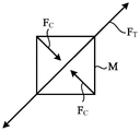
The winding direction Y1 in which the outer peripheral side reinforcing fibers 13a are wound around the core material 10 (the extending direction of the outer peripheral side reinforcing fibers 13 a) is along the direction of the tensile load among the load applied to the wire rod when the load of the compression coil spring 1 is applied from the outside, that is, the tensile load and the compressive load. Fig. 4A and 4B are schematic views showing the configuration of the main part of the coil spring according to the embodiment of the present invention, and are for explanationThe coil spring 1 is illustrated with a load acting on the surface of the wire when a torsional stress acts thereon. The coil spring 1 (wire rod) is subjected to a load F in opposite winding directions to each other as a load around the center axis of the wire rod1、F2When the torsional stress is applied, a shear stress τ shown in fig. 4A acts on a rectangular minute region M in the surface of the wire rod as viewed from the minute region M11、τ12、τ21、τ22. The wire being subjected to a shear stress tau11、τ12、τ21、τ22In other words, the tensile load F is as shown in FIG. 4BTAnd compressive load FCActs on the micro-area M. Despite the tensile load FTThe direction of action is theoretically 45 ° with respect to the longitudinal axis of the wire (axis N1), but the angular range is more than 40 ° and 50 ° or less in consideration of variations in the shape of the wire and the like.
The winding direction Y1 of the outer peripheral side reinforcing fiber 13a according to the present embodiment is along the tensile load FTPreferably all along the tensile load FTAnd (4) winding. The inner reinforcing fibers 12a and the outer reinforcing fibers 13a may be wound at different local winding angles, but are preferably wound around the core material 10 at fixed winding angles. The "fixed winding angle" referred to herein includes manufacturing variations in winding angle.
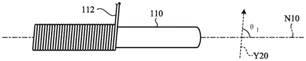
Fig. 5 is a schematic diagram showing the structure of a wire material for an elastic member as a wire material for manufacturing the coil spring 1. A wire rod 100 for an elastic member shown in the figure (hereinafter simply referred to as "wire rod 100") has a columnar shape with a three-layer structure, and includes a core material 110 having a columnar shape, and an FRP layer 111 formed by winding an inner peripheral side reinforcing fiber 112 around the outer periphery of the core material 110 and an outer peripheral side reinforcing fiber 113 around the outer periphery of the inner peripheral side reinforcing fiber 112 to form an inner peripheral side reinforcing fiber layer and an outer peripheral side reinforcing fiber layer, wherein the core material 110 is made of the same material as the core material 10, the inner peripheral side reinforcing fiber 112 is made of the same fiber as the inner peripheral side reinforcing fiber 12a, and the outer peripheral side reinforcing fiber 113 is made of the same fiber as the outer peripheral side reinforcing fiber 13 a. The inner-circumference-side reinforcing fibers 112 wound around the core member 110 and the outer-circumference-side reinforcing fibers 113 wound around the inner-circumference-side reinforcing fibers 112 may be impregnated with a liquid thermosetting resin in advance, or may be impregnated with a thermosetting resin after being wound separately.
Next, a method of manufacturing the wire 100 will be described with reference to fig. 6 and 7. Fig. 6 and 7 are views for explaining a method of manufacturing a wire material for an elastic member according to an embodiment of the present invention. First, the inner peripheral side reinforcing fibers 112 impregnated with a liquid thermosetting resin in advance are wound around the core material 110 (see fig. 6). At this time, an angle θ formed by the winding direction Y20 in which the inner peripheral side reinforcing fibers 112 are wound around the core material 110 (the extending direction of the inner peripheral side reinforcing fibers 112) and the longitudinal axis of the core material 110 (for example, the axis N10 shown in fig. 5)1Is 70 DEG or more and 110 DEG or less.
Then, the outer circumferential-side reinforcing fibers 113 impregnated with the liquid thermosetting resin are wound around the inner circumferential-side reinforcing fibers 112 (see fig. 7). At this time, the winding direction Y21 in which the outer-peripheral-side reinforcing fibers 113 are wound around the inner-peripheral-side reinforcing fibers 112 (the extending direction of the outer-peripheral-side reinforcing fibers 113) is, for example, along the direction of the tensile load when a load is applied from the outside to the coil spring 1 obtained by winding the wire rod 100 in a spiral shape. Specifically, the winding direction Y21 in which the outer-peripheral-side reinforcing fibers 113 are wound around the inner-peripheral-side reinforcing fibers 112 is an angle θ formed by the winding direction Y21 and the axis N10 when viewed from a direction orthogonal to the longitudinal axis (axis N10) of the core material 1102Is in the range of 40 DEG < theta2Less than or equal to 50 degrees. The angle theta2The angle corresponds to an angle formed by the direction of the tensile load acting on the outer-peripheral-side reinforcing fibers 113 due to the torsional stress and the central axis (axis N10) of the core material 110. As a method of Winding the inner-periphery-side reinforcing fibers 112 around the core material 110 and a method of Winding the outer-periphery-side reinforcing fibers 113 around the inner-periphery-side reinforcing fibers 112, for example, a Filament Winding (fiber Winding) method is given. In addition, in the case of using a reinforcing fiber bundle in which a plurality of reinforcing fibers are formed into a Sheet shape, it may be formed by a Sheet Winding (Sheet Winding) method.
After the outer circumferential-side reinforcing fibers 113 are wound, heating is performed to a temperature at which the thermosetting resin is cured or higher, whereby the wire rod 100 in which the inner circumferential-side reinforcing fibers 112 are fixed to each other, the outer circumferential-side reinforcing fibers 113 are fixed to each other, and/or the inner circumferential-side reinforcing fibers 112 and the outer circumferential-side reinforcing fibers 113 are fixed can be obtained.
As described above, as the strength when the wire 100 is used as a wire for a suspension spring, it is preferable that the rigidity modulus of the wire 100 is 9GPa or more and the static torsional strength of the wire 100 is 540MPa or more.
The coil spring 1 can be manufactured by winding the wire material 100. The wire 100 may be used as an elastic member such as a torsion bar (torsion bar) or a stabilizer (stabilizer) formed by bending a part thereof, in addition to the coil spring 1.
According to the above-described embodiment of the present invention, the coil spring 1 includes the core member 10 and the FRP layer 11 covering the outer surface of the core member 10, the FRP layer is composed of inner peripheral side reinforcing fibers 12a wound around a core material 10, outer peripheral side reinforcing fibers 13a wound around the inner peripheral side reinforcing fiber layer 12 containing the inner peripheral side reinforcing fibers 12a, and thermosetting resin for fixing the reinforcing fibers to each other, wherein the inner peripheral side reinforcing fiber 12a is wound so that the winding direction thereof with respect to the longitudinal axis (axis N1) of the core material 10 is 80 DEG to 100 DEG, the outer-peripheral-side reinforcing fibers 13a are wound so that the winding direction with respect to the core material 10 is a direction along the direction of the tensile load acting on the wire rod due to the torsional stress, whereby strength having resistance to the torsional stress can be achieved, and weight reduction can be achieved. For example, in the embodiment of the present invention, when aluminum, an alloy thereof, or a resin is used for the core material 10, the weight can be reduced by about 60% as compared with the case of using a coil spring having the same characteristics or volume, which is made of an iron-based material such as cast iron.
In the embodiment of the present invention, the core material 10 is provided on the inner periphery side of the inner periphery side reinforcing fiber layer 12, but the diameter reduction of the wire rod can be prevented by providing the inner periphery side reinforcing fiber layer 12, and therefore, a structure without the core material 10 may be adopted. That is, the hollow coil spring 1 (wire rod for elastic member) may be used which is constituted only by the FRP layer 11 including the inner peripheral side reinforcing fiber layer 12, the outer peripheral side reinforcing fiber layer 13, and the thermosetting resin for fixing the reinforcing fibers of these fiber layers.
Examples
Next, examples of the wire rod for an elastic member used for manufacturing a coil spring according to the present invention will be described. Further, the present invention is not limited to these examples. First, the structure of the elastic member wire material according to the present embodiment will be described.
Example 1
A rod-shaped polypropylene (PP) resin material is used as the core material, and a carbon fiber bundle containing an epoxy resin, that is, a tow prepreg (tow prepreg), is used as the inner-circumference-side reinforcing fiber and the outer-circumference-side reinforcing fiber.
As a wire material for elastic members, a tow prepreg is wound around a core material. First, the inner peripheral side reinforcing fibers are wound so as to form an angle of 90 ° with the core material longitudinal axis when viewed from the direction orthogonal to the core material longitudinal axis. The outer-peripheral-side reinforcing fibers were wound so as to form an angle of 45 ° with the core material longitudinal axis when viewed from a direction orthogonal to the core material longitudinal axis until the ratio of the thickness of the outer-peripheral-side reinforcing fiber layer to the thickness of the inner-peripheral-side reinforcing fiber layer became 4: 1. Then, the epoxy resin was cured to obtain a wire rod as the wire rod for an elastic member according to example 1.
Example 2
The procedure of example 1 was repeated except that the winding angle of the inner peripheral side reinforcing fibers with respect to the longitudinal axis of the core material was set to 80 °.
Example 3
The procedure of example 2 was repeated except that the ratio of the thickness of the outer-peripheral-side reinforcing fiber layer to the thickness of the inner-peripheral-side reinforcing fiber layer was set to 3: 2.
Example 4
The procedure of example 2 was repeated except that the ratio of the thickness of the outer-peripheral-side reinforcing fiber layer to the thickness of the inner-peripheral-side reinforcing fiber layer was set to 2: 3.
Example 5
The procedure of example 1 was repeated except that the winding angle of the inner peripheral side reinforcing fibers with respect to the longitudinal axis of the core material was set to 100 °.
Example 6
The procedure of example 1 was repeated except that the winding angle of the inner peripheral side reinforcing fibers with respect to the longitudinal axis of the core material was set to 70 °.
Comparative example 1
A rod-shaped polypropylene (PP) resin material was used as the core material, and a tow prepreg, which is a carbon fiber tow, was used as the reinforcing fiber.
For the wire rod for elastic member, a tow prepreg was wound around the core material using a filament winding machine. At this time, the reinforcing fibers were wound so as to form an angle of 45 ° with the core material longitudinal axis when viewed from the direction orthogonal to the core material longitudinal axis until the thickness of the outer-peripheral-side reinforcing fiber layer became equal to the sum of the thickness of the inner-peripheral-side reinforcing fiber layer and the thickness of the outer-peripheral-side reinforcing fiber layer of example 1, that is, until the ratio of the thickness of the outer-peripheral-side reinforcing fiber layer to the thickness of the inner-peripheral-side reinforcing fiber layer became 5: 0. Then, the epoxy resin was cured, and the obtained wire rod was used as the wire rod for the elastic member according to comparative example 1. Fig. 8 is a schematic diagram for explaining the structure of a coil spring of a comparative example according to an embodiment of the present invention. As shown in fig. 8, the wire material 200 for an elastic member according to comparative example 1 includes a core material 210 and an FRP layer 211 made of reinforcing fibers wound around the core material 210. The elastic member wire material 200 is formed by winding reinforcing fibers so as to form an angle of 45 ° with the longitudinal axis N100 of the core material 210.
Comparative example 2
The procedure of example 2 was repeated except that the ratio of the thickness of the outer-peripheral-side reinforcing fiber layer to the thickness of the inner-peripheral-side reinforcing fiber layer was 1: 4.
Comparative example 3
The procedure of example 1 was repeated except that the winding angle of the inner peripheral side reinforcing fibers with respect to the longitudinal axis of the core material was set to 60 °.
In examples 1 to 6 and comparative examples 1 to 3 described above, the diameter of the core material and the outer diameter of the elastic member wire material were uniform.
Next, the contents of the test according to the present example will be explained.
Torsional rupture strength test
The strain gauge was attached and the test was performed with the rotational speed around the center axis of the wire rod set to 0.3 °/second. The torsional breaking strength (static torsional strength) of the wire rod (carbon fiber) was obtained by this torsional test.
Modulus of rigidity
The rigidity modulus was calculated based on the slope of the stress-strain curve obtained by the above-described torsion test.
Next, table 1 shows the characteristics of the wire rod for an elastic member according to the present example, and the results of the torsion test (torsional rupture strength and modulus of rigidity). Here, the "layer thickness ratio" represents the ratio of the outer-peripheral-side reinforcing fiber layer to the inner-peripheral-side reinforcing fiber layer. The "fiber content" represents the volume content of the reinforcing fibers in the FRP layer.
TABLE 1

As shown in table 1, examples 1 to 6, which are wire rods for elastic members having inner-peripheral-side reinforcing fibers and outer-peripheral-side reinforcing fibers, had higher modulus of rigidity and torsional breaking strength than comparative example 1 in which reinforcing fibers were wound in one direction. The wire rods according to examples 1 and 2 have high modulus of rigidity and torsional breaking strength, and as a result, practical coil springs can be obtained using the wire rods.
Here, when the coil spring 1 is used for a suspension spring for suspension, it is preferable that the wire material for elastic member used to manufacture the coil spring 1 has a rigidity modulus of, for example, 9GPa or more and a static torsional strength of 540MPa or more. From the results of the present example, it can be seen that the wire rods for elastic members according to examples 1 to 6 can sufficiently satisfy the requirements as the wire rod for the coil spring 1 for suspension.
As described above, the present invention can cover various embodiments and the like not described herein, and various design changes and the like can be made without departing from the scope of the technical idea defined by the claims.
As described above, the wire material for elastic members and the elastic member according to the present invention facilitate weight reduction and strength improvement.
Description of the symbols
1 helical spring
10. 110 core material
11. 111 Fiber Reinforced Plastic (FRP) layer
12 inner peripheral side reinforcing fiber layer
12a, 112 inner peripheral side reinforcing fiber
13 outer circumference side reinforcing fiber layer
13a, 113 reinforcing fiber on outer peripheral side
100. 200 wire for elastic member
Claims (13)
1. A wire rod for elastic members, which is used for manufacturing an elastic member, is characterized by comprising:
an inner peripheral side reinforcing fiber wound in a spiral shape;
an outer peripheral side reinforcing fiber provided on an outer periphery of the inner peripheral side reinforcing fiber; and
a thermosetting resin provided on at least a part of the inner circumferential-side reinforcing fibers and the outer circumferential-side reinforcing fibers for fixing the reinforcing fibers to each other,
wherein an angle formed by a winding direction of the inner peripheral side reinforcing fiber and a central axis of the winding is 70 DEG to 110 DEG,
a winding direction of the outer-peripheral-side reinforcing fiber with respect to a central axis of winding is a direction along a direction of a tensile load applied to the wire rod for the elastic member based on a load applied from the outside to apply a torsional stress to the wire rod for the elastic member,
an angle formed by a central axis of winding of the outer peripheral side reinforcing fiber and a winding direction of the outer peripheral side reinforcing fiber is larger than 40 ° and not larger than 50 °.
2. The wire rod for elastic members according to claim 1, wherein:
the wire rod for elastic members has a modulus of rigidity of 9GPa or more.
3. The wire rod for elastic members according to claim 1 or 2, characterized in that:
the ratio of the thickness of the outer-peripheral-side reinforcing fiber layer containing the outer-peripheral-side reinforcing fibers to the thickness of the inner-peripheral-side reinforcing fiber layer containing the inner-peripheral-side reinforcing fibers is 0.5 or more.
4. The wire rod for elastic members according to claim 1 or 2, characterized in that:
the static torsional strength of the wire for elastic members is 540MPa or more.
5. The wire rod for elastic members according to claim 3, wherein:
the static torsional strength of the wire for elastic members is 540MPa or more.
6. The elastic member wire rod according to claim 1 or 2, further comprising:
and a core material formed using an elastically deformable material and provided on the inner periphery side of the tubular inner periphery side reinforcing fiber layer formed of the inner periphery side reinforcing fibers.
7. The elastic member wire rod according to claim 3, further comprising:
and a core material formed using an elastically deformable material and provided on the inner periphery side of the tubular inner periphery side reinforcing fiber layer formed of the inner periphery side reinforcing fibers.
8. The elastic member wire rod according to claim 4, further comprising:
and a core material formed using an elastically deformable material and provided on the inner periphery side of the tubular inner periphery side reinforcing fiber layer formed of the inner periphery side reinforcing fibers.
9. The elastic member wire rod according to claim 5, further comprising:
and a core material formed using an elastically deformable material and provided on the inner periphery side of the tubular inner periphery side reinforcing fiber layer formed of the inner periphery side reinforcing fibers.
10. The wire rod for elastic members according to claim 6, wherein:
the core material and the elastic member wire rod have a circular cross section obtained by using a plane orthogonal to the longitudinal axis as a cross section,
the angle formed by the winding direction of the inner peripheral side reinforcing fiber and the central axis of the winding is 80 DEG to 100 deg.
11. An elastic member characterized by:
the elastic member is formed using the elastic member wire material according to any one of claims 1 to 10.
12. The elastomeric component of claim 11, wherein:
the elastic member is formed by winding a wire material into a spiral shape.
13. The elastomeric component of claim 12, wherein:
the elastic member is a suspension spring for an automobile.
Applications Claiming Priority (3)
| Application Number | Priority Date | Filing Date | Title |
|---|---|---|---|
| JP2015213501A JP6502235B2 (en) | 2015-10-29 | 2015-10-29 | Wire member for elastic member and elastic member |
| JP2015-213501 | 2015-10-29 | ||
| PCT/JP2016/082174 WO2017073773A1 (en) | 2015-10-29 | 2016-10-28 | Wire for elastic member, and elastic member |
Publications (2)
| Publication Number | Publication Date |
|---|---|
| CN108350968A CN108350968A (en) | 2018-07-31 |
| CN108350968B true CN108350968B (en) | 2020-07-28 |
Family
ID=58630421
Family Applications (1)
| Application Number | Title | Priority Date | Filing Date |
|---|---|---|---|
| CN201680062789.0A Active CN108350968B (en) | 2015-10-29 | 2016-10-28 | Wire material for elastic member and elastic member |
Country Status (5)
| Country | Link |
|---|---|
| US (1) | US10828845B2 (en) |
| EP (1) | EP3369960B1 (en) |
| JP (1) | JP6502235B2 (en) |
| CN (1) | CN108350968B (en) |
| WO (1) | WO2017073773A1 (en) |
Families Citing this family (2)
| Publication number | Priority date | Publication date | Assignee | Title |
|---|---|---|---|---|
| MX2020002097A (en) * | 2017-08-24 | 2020-09-18 | Ressorts Liberte Inc | Coil spring and method of fabrication thereof. |
| FR3090461B1 (en) * | 2018-12-20 | 2021-12-03 | S Ara Composite | Composite rope |
Family Cites Families (15)
| Publication number | Priority date | Publication date | Assignee | Title |
|---|---|---|---|---|
| JPS5740373Y2 (en) | 1978-09-19 | 1982-09-04 | ||
| CA1154042A (en) * | 1979-07-12 | 1983-09-20 | Frank H. Doyal | Fiber-reinforced tubular spring |
| JPS6032539B2 (en) * | 1980-06-23 | 1985-07-29 | 日産自動車株式会社 | Coil spring manufacturing method |
| JPS5891940A (en) * | 1981-11-27 | 1983-06-01 | Mitsubishi Rayon Co Ltd | Coil spring consisting of compound material |
| US4473217A (en) * | 1982-01-07 | 1984-09-25 | Kato Hatsujo Kaisha, Limited | Fiber-reinforced resin coil spring and method of manufacturing the same |
| JPS59144837A (en) * | 1983-02-03 | 1984-08-20 | Hitachi Chem Co Ltd | Hollow-section coiled spring made of fiber reinforcing plastics and method of manufacturing the spring |
| JPS6117731A (en) * | 1984-07-02 | 1986-01-25 | Nhk Spring Co Ltd | Torsion bar |
| JPH04136530A (en) * | 1990-09-27 | 1992-05-11 | Toyama Pref Gov | Frp coil spring and manufacture thereof |
| JP3009311B2 (en) | 1993-08-04 | 2000-02-14 | 東邦レーヨン株式会社 | Fiber-reinforced resin coil spring and method of manufacturing the same |
| US20020190451A1 (en) * | 2001-06-01 | 2002-12-19 | The University Of Akron | Fiber-reinforced composite springs |
| CN1480658A (en) * | 2002-09-05 | 2004-03-10 | 私立逢甲大学 | Helical spring structure in knitting operation made from composite material and its manufacturing method |
| JP2006226327A (en) * | 2005-02-15 | 2006-08-31 | Kyoto Institute Of Technology | Frp coil spring and method for manufacturing the same |
| JP5735826B2 (en) | 2011-03-10 | 2015-06-17 | 日本発條株式会社 | Fiber reinforced plastic spring |
| DE102013016483A1 (en) * | 2013-10-04 | 2014-07-24 | Daimler Ag | Method for manufacturing fiber composite-torsion spring of vehicle, involves twisting blank before curing process in operating torsion direction, where blank is twisted around five to fifty percent of operating torsion angle |
| EP3434927A4 (en) * | 2016-03-23 | 2019-11-20 | NHK Spring Co., Ltd. | Coil spring |
-
2015
- 2015-10-29 JP JP2015213501A patent/JP6502235B2/en active Active
-
2016
- 2016-10-28 WO PCT/JP2016/082174 patent/WO2017073773A1/en active Application Filing
- 2016-10-28 EP EP16860001.3A patent/EP3369960B1/en active Active
- 2016-10-28 CN CN201680062789.0A patent/CN108350968B/en active Active
- 2016-10-28 US US15/768,212 patent/US10828845B2/en active Active
Also Published As
| Publication number | Publication date |
|---|---|
| EP3369960A4 (en) | 2019-07-03 |
| JP2017082966A (en) | 2017-05-18 |
| EP3369960B1 (en) | 2023-08-23 |
| US20180297297A1 (en) | 2018-10-18 |
| CN108350968A (en) | 2018-07-31 |
| JP6502235B2 (en) | 2019-04-17 |
| US10828845B2 (en) | 2020-11-10 |
| EP3369960A1 (en) | 2018-09-05 |
| WO2017073773A1 (en) | 2017-05-04 |
Similar Documents
| Publication | Publication Date | Title |
|---|---|---|
| US10240654B2 (en) | Hybrid spring device | |
| KR101858341B1 (en) | High pressure tank, method of manufacturing high pressure tank and method of designing liner shape | |
| EP2875254B1 (en) | Composite coil spring | |
| KR102181843B1 (en) | Torsion-loaded rod-shaped component with different fibre reinforcements for tensile and compressive loading | |
| JP6440847B2 (en) | Wire for elastic member and elastic member | |
| US10767720B2 (en) | Method for leaf springs made of fiber-reinforced plastic with integrated eye bushings, and leaf spring made of fiber-reinforced plastic | |
| CN108350968B (en) | Wire material for elastic member and elastic member | |
| JP6832338B2 (en) | Coil spring | |
| JPH0258493B2 (en) | ||
| JP4771209B2 (en) | FRP cylinder and manufacturing method thereof | |
| CN106460985B (en) | torsionally loaded rod-shaped member | |
| WO2017073772A1 (en) | Coil spring wire rod and coil spring | |
| US9233591B2 (en) | Fiber composite component and method for producing a fiber composite component | |
| CN111503265B (en) | High-pressure tank and method for manufacturing high-pressure tank | |
| WO2017043654A1 (en) | Method for producing wire rod for elastic members, wire rod for elastic members, and elastic member | |
| US20220412508A1 (en) | Tank and method of manufacturing the same | |
| JP2017082966A5 (en) | ||
| WO2017073771A1 (en) | Wire rod for elastic member, and elastic member | |
| US20190366617A1 (en) | Strand profile and process for producing a strand profile | |
| JPS5828029A (en) | Fiber reinforced plastic coil spring and its manufacture | |
| JP2008082525A (en) | Propeller shaft and its manufacturing method | |
| KR102391001B1 (en) | Coil spring of complex material and manufacturing method thereof | |
| JP2006062354A (en) | Frp cylindrical body and its manufacturing method |
Legal Events
| Date | Code | Title | Description |
|---|---|---|---|
| PB01 | Publication | ||
| PB01 | Publication | ||
| SE01 | Entry into force of request for substantive examination | ||
| SE01 | Entry into force of request for substantive examination | ||
| GR01 | Patent grant | ||
| GR01 | Patent grant |