CN108290350B - Securing a second object to a first object - Google Patents
Securing a second object to a first object Download PDFInfo
- Publication number
- CN108290350B CN108290350B CN201680069402.4A CN201680069402A CN108290350B CN 108290350 B CN108290350 B CN 108290350B CN 201680069402 A CN201680069402 A CN 201680069402A CN 108290350 B CN108290350 B CN 108290350B
- Authority
- CN
- China
- Prior art keywords
- sonotrode
- thermoplastic material
- rim
- fastener
- relative
- Prior art date
- Legal status (The legal status is an assumption and is not a legal conclusion. Google has not performed a legal analysis and makes no representation as to the accuracy of the status listed.)
- Active
Links
- 239000012815 thermoplastic material Substances 0.000 claims abstract description 210
- 238000000034 method Methods 0.000 claims abstract description 176
- 230000009969 flowable effect Effects 0.000 claims abstract description 47
- 239000007787 solid Substances 0.000 claims abstract description 10
- 238000010168 coupling process Methods 0.000 claims description 85
- 238000005859 coupling reaction Methods 0.000 claims description 85
- 230000008878 coupling Effects 0.000 claims description 81
- 229910052751 metal Inorganic materials 0.000 claims description 41
- 239000002184 metal Substances 0.000 claims description 41
- 238000003825 pressing Methods 0.000 claims description 40
- 230000002093 peripheral effect Effects 0.000 claims description 34
- 238000007789 sealing Methods 0.000 claims description 9
- 238000007373 indentation Methods 0.000 claims description 2
- 239000000463 material Substances 0.000 description 102
- 230000008569 process Effects 0.000 description 84
- 238000004873 anchoring Methods 0.000 description 68
- 230000002787 reinforcement Effects 0.000 description 36
- 239000000853 adhesive Substances 0.000 description 27
- 230000001070 adhesive effect Effects 0.000 description 27
- 229920001169 thermoplastic Polymers 0.000 description 21
- 238000004519 manufacturing process Methods 0.000 description 20
- 239000004416 thermosoftening plastic Substances 0.000 description 20
- 230000000694 effects Effects 0.000 description 15
- 238000002844 melting Methods 0.000 description 14
- 230000008018 melting Effects 0.000 description 14
- 238000010276 construction Methods 0.000 description 13
- 230000010355 oscillation Effects 0.000 description 10
- 238000012545 processing Methods 0.000 description 10
- 230000008901 benefit Effects 0.000 description 9
- 230000009477 glass transition Effects 0.000 description 9
- 238000013461 design Methods 0.000 description 8
- 238000004070 electrodeposition Methods 0.000 description 8
- 238000005304 joining Methods 0.000 description 8
- 230000035515 penetration Effects 0.000 description 8
- 229920000642 polymer Polymers 0.000 description 8
- 238000007711 solidification Methods 0.000 description 8
- 210000002105 tongue Anatomy 0.000 description 8
- 229920003023 plastic Polymers 0.000 description 7
- 239000004033 plastic Substances 0.000 description 7
- -1 polypropylene Polymers 0.000 description 7
- 238000013459 approach Methods 0.000 description 6
- 230000000712 assembly Effects 0.000 description 6
- 238000000429 assembly Methods 0.000 description 6
- 239000000203 mixture Substances 0.000 description 6
- 238000010521 absorption reaction Methods 0.000 description 5
- 239000000835 fiber Substances 0.000 description 5
- 238000010438 heat treatment Methods 0.000 description 5
- 238000003754 machining Methods 0.000 description 5
- 238000004080 punching Methods 0.000 description 5
- 229910000831 Steel Inorganic materials 0.000 description 4
- 229910052782 aluminium Inorganic materials 0.000 description 4
- 239000000919 ceramic Substances 0.000 description 4
- 230000001276 controlling effect Effects 0.000 description 4
- 238000011089 mechanical engineering Methods 0.000 description 4
- 125000006850 spacer group Chemical group 0.000 description 4
- 239000010959 steel Substances 0.000 description 4
- 238000003466 welding Methods 0.000 description 4
- 230000002411 adverse Effects 0.000 description 3
- XAGFODPZIPBFFR-UHFFFAOYSA-N aluminium Chemical compound [Al] XAGFODPZIPBFFR-UHFFFAOYSA-N 0.000 description 3
- 230000006399 behavior Effects 0.000 description 3
- 229910052799 carbon Inorganic materials 0.000 description 3
- 239000004917 carbon fiber Substances 0.000 description 3
- 238000005266 casting Methods 0.000 description 3
- 230000008859 change Effects 0.000 description 3
- 239000002131 composite material Substances 0.000 description 3
- 238000001816 cooling Methods 0.000 description 3
- 239000000945 filler Substances 0.000 description 3
- 230000004927 fusion Effects 0.000 description 3
- 239000003365 glass fiber Substances 0.000 description 3
- 238000001746 injection moulding Methods 0.000 description 3
- 238000005259 measurement Methods 0.000 description 3
- 238000004021 metal welding Methods 0.000 description 3
- 230000004048 modification Effects 0.000 description 3
- 238000012986 modification Methods 0.000 description 3
- 229920001707 polybutylene terephthalate Polymers 0.000 description 3
- 239000004417 polycarbonate Substances 0.000 description 3
- 229920000515 polycarbonate Polymers 0.000 description 3
- 229920000728 polyester Polymers 0.000 description 3
- 229920000139 polyethylene terephthalate Polymers 0.000 description 3
- 239000005020 polyethylene terephthalate Substances 0.000 description 3
- 238000004886 process control Methods 0.000 description 3
- 230000002829 reductive effect Effects 0.000 description 3
- OKTJSMMVPCPJKN-UHFFFAOYSA-N Carbon Chemical compound [C] OKTJSMMVPCPJKN-UHFFFAOYSA-N 0.000 description 2
- 229920000049 Carbon (fiber) Polymers 0.000 description 2
- 229920002430 Fibre-reinforced plastic Polymers 0.000 description 2
- 229920002302 Nylon 6,6 Polymers 0.000 description 2
- 239000004698 Polyethylene Substances 0.000 description 2
- 239000004743 Polypropylene Substances 0.000 description 2
- 239000004676 acrylonitrile butadiene styrene Substances 0.000 description 2
- 230000009471 action Effects 0.000 description 2
- 239000004411 aluminium Substances 0.000 description 2
- 238000005452 bending Methods 0.000 description 2
- 238000006243 chemical reaction Methods 0.000 description 2
- 238000005056 compaction Methods 0.000 description 2
- 238000012937 correction Methods 0.000 description 2
- 238000001514 detection method Methods 0.000 description 2
- 238000010586 diagram Methods 0.000 description 2
- 238000004512 die casting Methods 0.000 description 2
- 230000007613 environmental effect Effects 0.000 description 2
- 239000002657 fibrous material Substances 0.000 description 2
- 239000003292 glue Substances 0.000 description 2
- 238000003780 insertion Methods 0.000 description 2
- 230000037431 insertion Effects 0.000 description 2
- 230000001788 irregular Effects 0.000 description 2
- 239000007788 liquid Substances 0.000 description 2
- 230000013011 mating Effects 0.000 description 2
- 230000007246 mechanism Effects 0.000 description 2
- 239000002245 particle Substances 0.000 description 2
- 239000012071 phase Substances 0.000 description 2
- 229920001643 poly(ether ketone) Polymers 0.000 description 2
- 229920003229 poly(methyl methacrylate) Polymers 0.000 description 2
- 229920000573 polyethylene Polymers 0.000 description 2
- 239000004926 polymethyl methacrylate Substances 0.000 description 2
- 229920001155 polypropylene Polymers 0.000 description 2
- 229920002635 polyurethane Polymers 0.000 description 2
- 239000004814 polyurethane Substances 0.000 description 2
- 239000004800 polyvinyl chloride Substances 0.000 description 2
- 229920000915 polyvinyl chloride Polymers 0.000 description 2
- 230000005855 radiation Effects 0.000 description 2
- 230000001739 rebound effect Effects 0.000 description 2
- 230000002441 reversible effect Effects 0.000 description 2
- 238000007493 shaping process Methods 0.000 description 2
- 239000000243 solution Substances 0.000 description 2
- 229920002725 thermoplastic elastomer Polymers 0.000 description 2
- 238000012546 transfer Methods 0.000 description 2
- 239000002023 wood Substances 0.000 description 2
- ACYXOHNDKRVKLH-UHFFFAOYSA-N 5-phenylpenta-2,4-dienenitrile prop-2-enoic acid Chemical compound OC(=O)C=C.N#CC=CC=CC1=CC=CC=C1 ACYXOHNDKRVKLH-UHFFFAOYSA-N 0.000 description 1
- NLHHRLWOUZZQLW-UHFFFAOYSA-N Acrylonitrile Chemical compound C=CC#N NLHHRLWOUZZQLW-UHFFFAOYSA-N 0.000 description 1
- 229920002799 BoPET Polymers 0.000 description 1
- BVKZGUZCCUSVTD-UHFFFAOYSA-L Carbonate Chemical compound [O-]C([O-])=O BVKZGUZCCUSVTD-UHFFFAOYSA-L 0.000 description 1
- 229920000271 Kevlar® Polymers 0.000 description 1
- FYYHWMGAXLPEAU-UHFFFAOYSA-N Magnesium Chemical compound [Mg] FYYHWMGAXLPEAU-UHFFFAOYSA-N 0.000 description 1
- 239000005041 Mylar™ Substances 0.000 description 1
- 229920000571 Nylon 11 Polymers 0.000 description 1
- 229920000299 Nylon 12 Polymers 0.000 description 1
- 229920002292 Nylon 6 Polymers 0.000 description 1
- 229930040373 Paraformaldehyde Natural products 0.000 description 1
- 239000004952 Polyamide Substances 0.000 description 1
- 239000004793 Polystyrene Substances 0.000 description 1
- 229910052581 Si3N4 Inorganic materials 0.000 description 1
- 239000004433 Thermoplastic polyurethane Substances 0.000 description 1
- XECAHXYUAAWDEL-UHFFFAOYSA-N acrylonitrile butadiene styrene Chemical compound C=CC=C.C=CC#N.C=CC1=CC=CC=C1 XECAHXYUAAWDEL-UHFFFAOYSA-N 0.000 description 1
- 229920000122 acrylonitrile butadiene styrene Polymers 0.000 description 1
- 230000006978 adaptation Effects 0.000 description 1
- 238000004026 adhesive bonding Methods 0.000 description 1
- AZDRQVAHHNSJOQ-UHFFFAOYSA-N alumane Chemical compound [AlH3] AZDRQVAHHNSJOQ-UHFFFAOYSA-N 0.000 description 1
- 229920005601 base polymer Polymers 0.000 description 1
- 230000009286 beneficial effect Effects 0.000 description 1
- 230000015572 biosynthetic process Effects 0.000 description 1
- 210000000746 body region Anatomy 0.000 description 1
- 229910010293 ceramic material Inorganic materials 0.000 description 1
- 230000000295 complement effect Effects 0.000 description 1
- 230000003750 conditioning effect Effects 0.000 description 1
- 229920001577 copolymer Polymers 0.000 description 1
- 238000002425 crystallisation Methods 0.000 description 1
- 230000008025 crystallization Effects 0.000 description 1
- 230000006378 damage Effects 0.000 description 1
- 230000032798 delamination Effects 0.000 description 1
- 230000001934 delay Effects 0.000 description 1
- 230000001419 dependent effect Effects 0.000 description 1
- KZHJGOXRZJKJNY-UHFFFAOYSA-N dioxosilane;oxo(oxoalumanyloxy)alumane Chemical compound O=[Si]=O.O=[Si]=O.O=[Al]O[Al]=O.O=[Al]O[Al]=O.O=[Al]O[Al]=O KZHJGOXRZJKJNY-UHFFFAOYSA-N 0.000 description 1
- 238000006073 displacement reaction Methods 0.000 description 1
- 238000005553 drilling Methods 0.000 description 1
- 238000001125 extrusion Methods 0.000 description 1
- 239000011151 fibre-reinforced plastic Substances 0.000 description 1
- 239000011521 glass Substances 0.000 description 1
- 239000011796 hollow space material Substances 0.000 description 1
- 238000007654 immersion Methods 0.000 description 1
- 230000006698 induction Effects 0.000 description 1
- 230000002427 irreversible effect Effects 0.000 description 1
- 239000004761 kevlar Substances 0.000 description 1
- 239000003562 lightweight material Substances 0.000 description 1
- 239000007791 liquid phase Substances 0.000 description 1
- 239000003550 marker Substances 0.000 description 1
- 239000011159 matrix material Substances 0.000 description 1
- VNWKTOKETHGBQD-UHFFFAOYSA-N methane Chemical compound C VNWKTOKETHGBQD-UHFFFAOYSA-N 0.000 description 1
- 229910052863 mullite Inorganic materials 0.000 description 1
- 230000003287 optical effect Effects 0.000 description 1
- 238000010422 painting Methods 0.000 description 1
- 230000036961 partial effect Effects 0.000 description 1
- 239000011236 particulate material Substances 0.000 description 1
- 235000011837 pasties Nutrition 0.000 description 1
- 229910052698 phosphorus Inorganic materials 0.000 description 1
- 229920002647 polyamide Polymers 0.000 description 1
- 229920001601 polyetherimide Polymers 0.000 description 1
- 239000002861 polymer material Substances 0.000 description 1
- 229920006324 polyoxymethylene Polymers 0.000 description 1
- 229920001296 polysiloxane Polymers 0.000 description 1
- 229920002223 polystyrene Polymers 0.000 description 1
- 229920001343 polytetrafluoroethylene Polymers 0.000 description 1
- 239000004810 polytetrafluoroethylene Substances 0.000 description 1
- 230000008092 positive effect Effects 0.000 description 1
- 239000000843 powder Substances 0.000 description 1
- SCUZVMOVTVSBLE-UHFFFAOYSA-N prop-2-enenitrile;styrene Chemical compound C=CC#N.C=CC1=CC=CC=C1 SCUZVMOVTVSBLE-UHFFFAOYSA-N 0.000 description 1
- 230000000644 propagated effect Effects 0.000 description 1
- 238000005086 pumping Methods 0.000 description 1
- 230000001105 regulatory effect Effects 0.000 description 1
- 230000003014 reinforcing effect Effects 0.000 description 1
- 239000012783 reinforcing fiber Substances 0.000 description 1
- 230000000717 retained effect Effects 0.000 description 1
- 238000005096 rolling process Methods 0.000 description 1
- 238000010079 rubber tapping Methods 0.000 description 1
- 239000000565 sealant Substances 0.000 description 1
- 238000000926 separation method Methods 0.000 description 1
- 238000007652 sheet-forming process Methods 0.000 description 1
- 229910052710 silicon Inorganic materials 0.000 description 1
- HBMJWWWQQXIZIP-UHFFFAOYSA-N silicon carbide Chemical compound [Si+]#[C-] HBMJWWWQQXIZIP-UHFFFAOYSA-N 0.000 description 1
- 229910010271 silicon carbide Inorganic materials 0.000 description 1
- HQVNEWCFYHHQES-UHFFFAOYSA-N silicon nitride Chemical compound N12[Si]34N5[Si]62N3[Si]51N64 HQVNEWCFYHHQES-UHFFFAOYSA-N 0.000 description 1
- 239000007790 solid phase Substances 0.000 description 1
- 229920000638 styrene acrylonitrile Polymers 0.000 description 1
- 229910052717 sulfur Inorganic materials 0.000 description 1
- 229920002803 thermoplastic polyurethane Polymers 0.000 description 1
- 239000004634 thermosetting polymer Substances 0.000 description 1
- 229920001187 thermosetting polymer Polymers 0.000 description 1
- 238000002604 ultrasonography Methods 0.000 description 1
- XLYOFNOQVPJJNP-UHFFFAOYSA-N water Substances O XLYOFNOQVPJJNP-UHFFFAOYSA-N 0.000 description 1
Images


Classifications
-
- B—PERFORMING OPERATIONS; TRANSPORTING
- B29—WORKING OF PLASTICS; WORKING OF SUBSTANCES IN A PLASTIC STATE IN GENERAL
- B29C—SHAPING OR JOINING OF PLASTICS; SHAPING OF MATERIAL IN A PLASTIC STATE, NOT OTHERWISE PROVIDED FOR; AFTER-TREATMENT OF THE SHAPED PRODUCTS, e.g. REPAIRING
- B29C65/00—Joining or sealing of preformed parts, e.g. welding of plastics materials; Apparatus therefor
- B29C65/02—Joining or sealing of preformed parts, e.g. welding of plastics materials; Apparatus therefor by heating, with or without pressure
- B29C65/06—Joining or sealing of preformed parts, e.g. welding of plastics materials; Apparatus therefor by heating, with or without pressure using friction, e.g. spin welding
-
- B—PERFORMING OPERATIONS; TRANSPORTING
- B29—WORKING OF PLASTICS; WORKING OF SUBSTANCES IN A PLASTIC STATE IN GENERAL
- B29C—SHAPING OR JOINING OF PLASTICS; SHAPING OF MATERIAL IN A PLASTIC STATE, NOT OTHERWISE PROVIDED FOR; AFTER-TREATMENT OF THE SHAPED PRODUCTS, e.g. REPAIRING
- B29C65/00—Joining or sealing of preformed parts, e.g. welding of plastics materials; Apparatus therefor
- B29C65/02—Joining or sealing of preformed parts, e.g. welding of plastics materials; Apparatus therefor by heating, with or without pressure
- B29C65/08—Joining or sealing of preformed parts, e.g. welding of plastics materials; Apparatus therefor by heating, with or without pressure using ultrasonic vibrations
- B29C65/088—Joining or sealing of preformed parts, e.g. welding of plastics materials; Apparatus therefor by heating, with or without pressure using ultrasonic vibrations using several cooperating sonotrodes, i.e. interacting with each other, e.g. for realising the same joint
-
- B—PERFORMING OPERATIONS; TRANSPORTING
- B29—WORKING OF PLASTICS; WORKING OF SUBSTANCES IN A PLASTIC STATE IN GENERAL
- B29C—SHAPING OR JOINING OF PLASTICS; SHAPING OF MATERIAL IN A PLASTIC STATE, NOT OTHERWISE PROVIDED FOR; AFTER-TREATMENT OF THE SHAPED PRODUCTS, e.g. REPAIRING
- B29C65/00—Joining or sealing of preformed parts, e.g. welding of plastics materials; Apparatus therefor
- B29C65/56—Joining or sealing of preformed parts, e.g. welding of plastics materials; Apparatus therefor using mechanical means or mechanical connections, e.g. form-fits
- B29C65/562—Joining or sealing of preformed parts, e.g. welding of plastics materials; Apparatus therefor using mechanical means or mechanical connections, e.g. form-fits using extra joining elements, i.e. which are not integral with the parts to be joined
- B29C65/564—Joining or sealing of preformed parts, e.g. welding of plastics materials; Apparatus therefor using mechanical means or mechanical connections, e.g. form-fits using extra joining elements, i.e. which are not integral with the parts to be joined hidden in the joint, e.g. dowels or Z-pins
-
- B—PERFORMING OPERATIONS; TRANSPORTING
- B29—WORKING OF PLASTICS; WORKING OF SUBSTANCES IN A PLASTIC STATE IN GENERAL
- B29C—SHAPING OR JOINING OF PLASTICS; SHAPING OF MATERIAL IN A PLASTIC STATE, NOT OTHERWISE PROVIDED FOR; AFTER-TREATMENT OF THE SHAPED PRODUCTS, e.g. REPAIRING
- B29C65/00—Joining or sealing of preformed parts, e.g. welding of plastics materials; Apparatus therefor
- B29C65/56—Joining or sealing of preformed parts, e.g. welding of plastics materials; Apparatus therefor using mechanical means or mechanical connections, e.g. form-fits
- B29C65/60—Riveting or staking
- B29C65/606—Riveting or staking the rivets being integral with one of the parts to be joined, i.e. staking
-
- B—PERFORMING OPERATIONS; TRANSPORTING
- B29—WORKING OF PLASTICS; WORKING OF SUBSTANCES IN A PLASTIC STATE IN GENERAL
- B29C—SHAPING OR JOINING OF PLASTICS; SHAPING OF MATERIAL IN A PLASTIC STATE, NOT OTHERWISE PROVIDED FOR; AFTER-TREATMENT OF THE SHAPED PRODUCTS, e.g. REPAIRING
- B29C65/00—Joining or sealing of preformed parts, e.g. welding of plastics materials; Apparatus therefor
- B29C65/56—Joining or sealing of preformed parts, e.g. welding of plastics materials; Apparatus therefor using mechanical means or mechanical connections, e.g. form-fits
- B29C65/64—Joining a non-plastics element to a plastics element, e.g. by force
- B29C65/645—Joining a non-plastics element to a plastics element, e.g. by force using friction or ultrasonic vibrations
-
- B—PERFORMING OPERATIONS; TRANSPORTING
- B29—WORKING OF PLASTICS; WORKING OF SUBSTANCES IN A PLASTIC STATE IN GENERAL
- B29C—SHAPING OR JOINING OF PLASTICS; SHAPING OF MATERIAL IN A PLASTIC STATE, NOT OTHERWISE PROVIDED FOR; AFTER-TREATMENT OF THE SHAPED PRODUCTS, e.g. REPAIRING
- B29C65/00—Joining or sealing of preformed parts, e.g. welding of plastics materials; Apparatus therefor
- B29C65/78—Means for handling the parts to be joined, e.g. for making containers or hollow articles, e.g. means for handling sheets, plates, web-like materials, tubular articles, hollow articles or elements to be joined therewith; Means for discharging the joined articles from the joining apparatus
- B29C65/7802—Positioning the parts to be joined, e.g. aligning, indexing or centring
- B29C65/7805—Positioning the parts to be joined, e.g. aligning, indexing or centring the parts to be joined comprising positioning features
- B29C65/7808—Positioning the parts to be joined, e.g. aligning, indexing or centring the parts to be joined comprising positioning features in the form of holes or slots
- B29C65/7811—Positioning the parts to be joined, e.g. aligning, indexing or centring the parts to be joined comprising positioning features in the form of holes or slots for centring purposes
-
- B—PERFORMING OPERATIONS; TRANSPORTING
- B29—WORKING OF PLASTICS; WORKING OF SUBSTANCES IN A PLASTIC STATE IN GENERAL
- B29C—SHAPING OR JOINING OF PLASTICS; SHAPING OF MATERIAL IN A PLASTIC STATE, NOT OTHERWISE PROVIDED FOR; AFTER-TREATMENT OF THE SHAPED PRODUCTS, e.g. REPAIRING
- B29C66/00—General aspects of processes or apparatus for joining preformed parts
- B29C66/01—General aspects dealing with the joint area or with the area to be joined
- B29C66/05—Particular design of joint configurations
- B29C66/10—Particular design of joint configurations particular design of the joint cross-sections
- B29C66/11—Joint cross-sections comprising a single joint-segment, i.e. one of the parts to be joined comprising a single joint-segment in the joint cross-section
- B29C66/112—Single lapped joints
- B29C66/1122—Single lap to lap joints, i.e. overlap joints
-
- B—PERFORMING OPERATIONS; TRANSPORTING
- B29—WORKING OF PLASTICS; WORKING OF SUBSTANCES IN A PLASTIC STATE IN GENERAL
- B29C—SHAPING OR JOINING OF PLASTICS; SHAPING OF MATERIAL IN A PLASTIC STATE, NOT OTHERWISE PROVIDED FOR; AFTER-TREATMENT OF THE SHAPED PRODUCTS, e.g. REPAIRING
- B29C66/00—General aspects of processes or apparatus for joining preformed parts
- B29C66/01—General aspects dealing with the joint area or with the area to be joined
- B29C66/05—Particular design of joint configurations
- B29C66/20—Particular design of joint configurations particular design of the joint lines, e.g. of the weld lines
- B29C66/21—Particular design of joint configurations particular design of the joint lines, e.g. of the weld lines said joint lines being formed by a single dot or dash or by several dots or dashes, i.e. spot joining or spot welding
-
- B—PERFORMING OPERATIONS; TRANSPORTING
- B29—WORKING OF PLASTICS; WORKING OF SUBSTANCES IN A PLASTIC STATE IN GENERAL
- B29C—SHAPING OR JOINING OF PLASTICS; SHAPING OF MATERIAL IN A PLASTIC STATE, NOT OTHERWISE PROVIDED FOR; AFTER-TREATMENT OF THE SHAPED PRODUCTS, e.g. REPAIRING
- B29C66/00—General aspects of processes or apparatus for joining preformed parts
- B29C66/01—General aspects dealing with the joint area or with the area to be joined
- B29C66/05—Particular design of joint configurations
- B29C66/302—Particular design of joint configurations the area to be joined comprising melt initiators
- B29C66/3022—Particular design of joint configurations the area to be joined comprising melt initiators said melt initiators being integral with at least one of the parts to be joined
- B29C66/30221—Particular design of joint configurations the area to be joined comprising melt initiators said melt initiators being integral with at least one of the parts to be joined said melt initiators being point-like
-
- B—PERFORMING OPERATIONS; TRANSPORTING
- B29—WORKING OF PLASTICS; WORKING OF SUBSTANCES IN A PLASTIC STATE IN GENERAL
- B29C—SHAPING OR JOINING OF PLASTICS; SHAPING OF MATERIAL IN A PLASTIC STATE, NOT OTHERWISE PROVIDED FOR; AFTER-TREATMENT OF THE SHAPED PRODUCTS, e.g. REPAIRING
- B29C66/00—General aspects of processes or apparatus for joining preformed parts
- B29C66/01—General aspects dealing with the joint area or with the area to be joined
- B29C66/05—Particular design of joint configurations
- B29C66/302—Particular design of joint configurations the area to be joined comprising melt initiators
- B29C66/3022—Particular design of joint configurations the area to be joined comprising melt initiators said melt initiators being integral with at least one of the parts to be joined
- B29C66/30223—Particular design of joint configurations the area to be joined comprising melt initiators said melt initiators being integral with at least one of the parts to be joined said melt initiators being rib-like
-
- B—PERFORMING OPERATIONS; TRANSPORTING
- B29—WORKING OF PLASTICS; WORKING OF SUBSTANCES IN A PLASTIC STATE IN GENERAL
- B29C—SHAPING OR JOINING OF PLASTICS; SHAPING OF MATERIAL IN A PLASTIC STATE, NOT OTHERWISE PROVIDED FOR; AFTER-TREATMENT OF THE SHAPED PRODUCTS, e.g. REPAIRING
- B29C66/00—General aspects of processes or apparatus for joining preformed parts
- B29C66/40—General aspects of joining substantially flat articles, e.g. plates, sheets or web-like materials; Making flat seams in tubular or hollow articles; Joining single elements to substantially flat surfaces
- B29C66/41—Joining substantially flat articles ; Making flat seams in tubular or hollow articles
- B29C66/43—Joining a relatively small portion of the surface of said articles
-
- B—PERFORMING OPERATIONS; TRANSPORTING
- B29—WORKING OF PLASTICS; WORKING OF SUBSTANCES IN A PLASTIC STATE IN GENERAL
- B29C—SHAPING OR JOINING OF PLASTICS; SHAPING OF MATERIAL IN A PLASTIC STATE, NOT OTHERWISE PROVIDED FOR; AFTER-TREATMENT OF THE SHAPED PRODUCTS, e.g. REPAIRING
- B29C66/00—General aspects of processes or apparatus for joining preformed parts
- B29C66/40—General aspects of joining substantially flat articles, e.g. plates, sheets or web-like materials; Making flat seams in tubular or hollow articles; Joining single elements to substantially flat surfaces
- B29C66/47—Joining single elements to sheets, plates or other substantially flat surfaces
- B29C66/474—Joining single elements to sheets, plates or other substantially flat surfaces said single elements being substantially non-flat
-
- B—PERFORMING OPERATIONS; TRANSPORTING
- B29—WORKING OF PLASTICS; WORKING OF SUBSTANCES IN A PLASTIC STATE IN GENERAL
- B29C—SHAPING OR JOINING OF PLASTICS; SHAPING OF MATERIAL IN A PLASTIC STATE, NOT OTHERWISE PROVIDED FOR; AFTER-TREATMENT OF THE SHAPED PRODUCTS, e.g. REPAIRING
- B29C66/00—General aspects of processes or apparatus for joining preformed parts
- B29C66/70—General aspects of processes or apparatus for joining preformed parts characterised by the composition, physical properties or the structure of the material of the parts to be joined; Joining with non-plastics material
- B29C66/73—General aspects of processes or apparatus for joining preformed parts characterised by the composition, physical properties or the structure of the material of the parts to be joined; Joining with non-plastics material characterised by the intensive physical properties of the material of the parts to be joined, by the optical properties of the material of the parts to be joined, by the extensive physical properties of the parts to be joined, by the state of the material of the parts to be joined or by the material of the parts to be joined being a thermoplastic or a thermoset
- B29C66/739—General aspects of processes or apparatus for joining preformed parts characterised by the composition, physical properties or the structure of the material of the parts to be joined; Joining with non-plastics material characterised by the intensive physical properties of the material of the parts to be joined, by the optical properties of the material of the parts to be joined, by the extensive physical properties of the parts to be joined, by the state of the material of the parts to be joined or by the material of the parts to be joined being a thermoplastic or a thermoset characterised by the material of the parts to be joined being a thermoplastic or a thermoset
- B29C66/7392—General aspects of processes or apparatus for joining preformed parts characterised by the composition, physical properties or the structure of the material of the parts to be joined; Joining with non-plastics material characterised by the intensive physical properties of the material of the parts to be joined, by the optical properties of the material of the parts to be joined, by the extensive physical properties of the parts to be joined, by the state of the material of the parts to be joined or by the material of the parts to be joined being a thermoplastic or a thermoset characterised by the material of the parts to be joined being a thermoplastic or a thermoset characterised by the material of at least one of the parts being a thermoplastic
-
- B—PERFORMING OPERATIONS; TRANSPORTING
- B29—WORKING OF PLASTICS; WORKING OF SUBSTANCES IN A PLASTIC STATE IN GENERAL
- B29C—SHAPING OR JOINING OF PLASTICS; SHAPING OF MATERIAL IN A PLASTIC STATE, NOT OTHERWISE PROVIDED FOR; AFTER-TREATMENT OF THE SHAPED PRODUCTS, e.g. REPAIRING
- B29C66/00—General aspects of processes or apparatus for joining preformed parts
- B29C66/70—General aspects of processes or apparatus for joining preformed parts characterised by the composition, physical properties or the structure of the material of the parts to be joined; Joining with non-plastics material
- B29C66/74—Joining plastics material to non-plastics material
- B29C66/742—Joining plastics material to non-plastics material to metals or their alloys
- B29C66/7422—Aluminium or alloys of aluminium
-
- B—PERFORMING OPERATIONS; TRANSPORTING
- B29—WORKING OF PLASTICS; WORKING OF SUBSTANCES IN A PLASTIC STATE IN GENERAL
- B29C—SHAPING OR JOINING OF PLASTICS; SHAPING OF MATERIAL IN A PLASTIC STATE, NOT OTHERWISE PROVIDED FOR; AFTER-TREATMENT OF THE SHAPED PRODUCTS, e.g. REPAIRING
- B29C66/00—General aspects of processes or apparatus for joining preformed parts
- B29C66/70—General aspects of processes or apparatus for joining preformed parts characterised by the composition, physical properties or the structure of the material of the parts to be joined; Joining with non-plastics material
- B29C66/74—Joining plastics material to non-plastics material
- B29C66/742—Joining plastics material to non-plastics material to metals or their alloys
- B29C66/7428—Transition metals or their alloys
- B29C66/74283—Iron or alloys of iron, e.g. steel
-
- B—PERFORMING OPERATIONS; TRANSPORTING
- B29—WORKING OF PLASTICS; WORKING OF SUBSTANCES IN A PLASTIC STATE IN GENERAL
- B29C—SHAPING OR JOINING OF PLASTICS; SHAPING OF MATERIAL IN A PLASTIC STATE, NOT OTHERWISE PROVIDED FOR; AFTER-TREATMENT OF THE SHAPED PRODUCTS, e.g. REPAIRING
- B29C66/00—General aspects of processes or apparatus for joining preformed parts
- B29C66/80—General aspects of machine operations or constructions and parts thereof
- B29C66/83—General aspects of machine operations or constructions and parts thereof characterised by the movement of the joining or pressing tools
- B29C66/832—Reciprocating joining or pressing tools
- B29C66/8322—Joining or pressing tools reciprocating along one axis
- B29C66/83221—Joining or pressing tools reciprocating along one axis cooperating reciprocating tools, each tool reciprocating along one axis
-
- B—PERFORMING OPERATIONS; TRANSPORTING
- B29—WORKING OF PLASTICS; WORKING OF SUBSTANCES IN A PLASTIC STATE IN GENERAL
- B29C—SHAPING OR JOINING OF PLASTICS; SHAPING OF MATERIAL IN A PLASTIC STATE, NOT OTHERWISE PROVIDED FOR; AFTER-TREATMENT OF THE SHAPED PRODUCTS, e.g. REPAIRING
- B29C66/00—General aspects of processes or apparatus for joining preformed parts
- B29C66/90—Measuring or controlling the joining process
- B29C66/92—Measuring or controlling the joining process by measuring or controlling the pressure, the force, the mechanical power or the displacement of the joining tools
- B29C66/929—Measuring or controlling the joining process by measuring or controlling the pressure, the force, the mechanical power or the displacement of the joining tools characterized by specific pressure, force, mechanical power or displacement values or ranges
- B29C66/9292—Measuring or controlling the joining process by measuring or controlling the pressure, the force, the mechanical power or the displacement of the joining tools characterized by specific pressure, force, mechanical power or displacement values or ranges in explicit relation to another variable, e.g. pressure diagrams
- B29C66/92921—Measuring or controlling the joining process by measuring or controlling the pressure, the force, the mechanical power or the displacement of the joining tools characterized by specific pressure, force, mechanical power or displacement values or ranges in explicit relation to another variable, e.g. pressure diagrams in specific relation to time, e.g. pressure-time diagrams
-
- B—PERFORMING OPERATIONS; TRANSPORTING
- B29—WORKING OF PLASTICS; WORKING OF SUBSTANCES IN A PLASTIC STATE IN GENERAL
- B29C—SHAPING OR JOINING OF PLASTICS; SHAPING OF MATERIAL IN A PLASTIC STATE, NOT OTHERWISE PROVIDED FOR; AFTER-TREATMENT OF THE SHAPED PRODUCTS, e.g. REPAIRING
- B29C2793/00—Shaping techniques involving a cutting or machining operation
- B29C2793/0045—Perforating
-
- B—PERFORMING OPERATIONS; TRANSPORTING
- B29—WORKING OF PLASTICS; WORKING OF SUBSTANCES IN A PLASTIC STATE IN GENERAL
- B29C—SHAPING OR JOINING OF PLASTICS; SHAPING OF MATERIAL IN A PLASTIC STATE, NOT OTHERWISE PROVIDED FOR; AFTER-TREATMENT OF THE SHAPED PRODUCTS, e.g. REPAIRING
- B29C2793/00—Shaping techniques involving a cutting or machining operation
- B29C2793/0081—Shaping techniques involving a cutting or machining operation before shaping
-
- B—PERFORMING OPERATIONS; TRANSPORTING
- B29—WORKING OF PLASTICS; WORKING OF SUBSTANCES IN A PLASTIC STATE IN GENERAL
- B29C—SHAPING OR JOINING OF PLASTICS; SHAPING OF MATERIAL IN A PLASTIC STATE, NOT OTHERWISE PROVIDED FOR; AFTER-TREATMENT OF THE SHAPED PRODUCTS, e.g. REPAIRING
- B29C65/00—Joining or sealing of preformed parts, e.g. welding of plastics materials; Apparatus therefor
- B29C65/02—Joining or sealing of preformed parts, e.g. welding of plastics materials; Apparatus therefor by heating, with or without pressure
- B29C65/06—Joining or sealing of preformed parts, e.g. welding of plastics materials; Apparatus therefor by heating, with or without pressure using friction, e.g. spin welding
- B29C65/0609—Joining or sealing of preformed parts, e.g. welding of plastics materials; Apparatus therefor by heating, with or without pressure using friction, e.g. spin welding characterised by the movement of the parts to be joined
- B29C65/0627—Angular, i.e. torsional
-
- B—PERFORMING OPERATIONS; TRANSPORTING
- B29—WORKING OF PLASTICS; WORKING OF SUBSTANCES IN A PLASTIC STATE IN GENERAL
- B29C—SHAPING OR JOINING OF PLASTICS; SHAPING OF MATERIAL IN A PLASTIC STATE, NOT OTHERWISE PROVIDED FOR; AFTER-TREATMENT OF THE SHAPED PRODUCTS, e.g. REPAIRING
- B29C65/00—Joining or sealing of preformed parts, e.g. welding of plastics materials; Apparatus therefor
- B29C65/56—Joining or sealing of preformed parts, e.g. welding of plastics materials; Apparatus therefor using mechanical means or mechanical connections, e.g. form-fits
- B29C65/60—Riveting or staking
- B29C65/606—Riveting or staking the rivets being integral with one of the parts to be joined, i.e. staking
- B29C65/608—Riveting or staking the rivets being integral with one of the parts to be joined, i.e. staking the integral rivets being pushed in blind holes
-
- B—PERFORMING OPERATIONS; TRANSPORTING
- B29—WORKING OF PLASTICS; WORKING OF SUBSTANCES IN A PLASTIC STATE IN GENERAL
- B29C—SHAPING OR JOINING OF PLASTICS; SHAPING OF MATERIAL IN A PLASTIC STATE, NOT OTHERWISE PROVIDED FOR; AFTER-TREATMENT OF THE SHAPED PRODUCTS, e.g. REPAIRING
- B29C65/00—Joining or sealing of preformed parts, e.g. welding of plastics materials; Apparatus therefor
- B29C65/56—Joining or sealing of preformed parts, e.g. welding of plastics materials; Apparatus therefor using mechanical means or mechanical connections, e.g. form-fits
- B29C65/64—Joining a non-plastics element to a plastics element, e.g. by force
-
- B—PERFORMING OPERATIONS; TRANSPORTING
- B29—WORKING OF PLASTICS; WORKING OF SUBSTANCES IN A PLASTIC STATE IN GENERAL
- B29C—SHAPING OR JOINING OF PLASTICS; SHAPING OF MATERIAL IN A PLASTIC STATE, NOT OTHERWISE PROVIDED FOR; AFTER-TREATMENT OF THE SHAPED PRODUCTS, e.g. REPAIRING
- B29C66/00—General aspects of processes or apparatus for joining preformed parts
- B29C66/01—General aspects dealing with the joint area or with the area to be joined
- B29C66/02—Preparation of the material, in the area to be joined, prior to joining or welding
- B29C66/024—Thermal pre-treatments
- B29C66/0242—Heating, or preheating, e.g. drying
-
- B—PERFORMING OPERATIONS; TRANSPORTING
- B29—WORKING OF PLASTICS; WORKING OF SUBSTANCES IN A PLASTIC STATE IN GENERAL
- B29C—SHAPING OR JOINING OF PLASTICS; SHAPING OF MATERIAL IN A PLASTIC STATE, NOT OTHERWISE PROVIDED FOR; AFTER-TREATMENT OF THE SHAPED PRODUCTS, e.g. REPAIRING
- B29C66/00—General aspects of processes or apparatus for joining preformed parts
- B29C66/01—General aspects dealing with the joint area or with the area to be joined
- B29C66/05—Particular design of joint configurations
- B29C66/303—Particular design of joint configurations the joint involving an anchoring effect
- B29C66/3032—Particular design of joint configurations the joint involving an anchoring effect making use of protusions or cavities belonging to at least one of the parts to be joined
- B29C66/30321—Particular design of joint configurations the joint involving an anchoring effect making use of protusions or cavities belonging to at least one of the parts to be joined making use of protusions belonging to at least one of the parts to be joined
-
- B—PERFORMING OPERATIONS; TRANSPORTING
- B29—WORKING OF PLASTICS; WORKING OF SUBSTANCES IN A PLASTIC STATE IN GENERAL
- B29C—SHAPING OR JOINING OF PLASTICS; SHAPING OF MATERIAL IN A PLASTIC STATE, NOT OTHERWISE PROVIDED FOR; AFTER-TREATMENT OF THE SHAPED PRODUCTS, e.g. REPAIRING
- B29C66/00—General aspects of processes or apparatus for joining preformed parts
- B29C66/40—General aspects of joining substantially flat articles, e.g. plates, sheets or web-like materials; Making flat seams in tubular or hollow articles; Joining single elements to substantially flat surfaces
- B29C66/47—Joining single elements to sheets, plates or other substantially flat surfaces
- B29C66/472—Joining single elements to sheets, plates or other substantially flat surfaces said single elements being substantially flat
-
- B—PERFORMING OPERATIONS; TRANSPORTING
- B29—WORKING OF PLASTICS; WORKING OF SUBSTANCES IN A PLASTIC STATE IN GENERAL
- B29C—SHAPING OR JOINING OF PLASTICS; SHAPING OF MATERIAL IN A PLASTIC STATE, NOT OTHERWISE PROVIDED FOR; AFTER-TREATMENT OF THE SHAPED PRODUCTS, e.g. REPAIRING
- B29C66/00—General aspects of processes or apparatus for joining preformed parts
- B29C66/70—General aspects of processes or apparatus for joining preformed parts characterised by the composition, physical properties or the structure of the material of the parts to be joined; Joining with non-plastics material
- B29C66/71—General aspects of processes or apparatus for joining preformed parts characterised by the composition, physical properties or the structure of the material of the parts to be joined; Joining with non-plastics material characterised by the composition of the plastics material of the parts to be joined
-
- B—PERFORMING OPERATIONS; TRANSPORTING
- B29—WORKING OF PLASTICS; WORKING OF SUBSTANCES IN A PLASTIC STATE IN GENERAL
- B29C—SHAPING OR JOINING OF PLASTICS; SHAPING OF MATERIAL IN A PLASTIC STATE, NOT OTHERWISE PROVIDED FOR; AFTER-TREATMENT OF THE SHAPED PRODUCTS, e.g. REPAIRING
- B29C66/00—General aspects of processes or apparatus for joining preformed parts
- B29C66/70—General aspects of processes or apparatus for joining preformed parts characterised by the composition, physical properties or the structure of the material of the parts to be joined; Joining with non-plastics material
- B29C66/72—General aspects of processes or apparatus for joining preformed parts characterised by the composition, physical properties or the structure of the material of the parts to be joined; Joining with non-plastics material characterised by the structure of the material of the parts to be joined
- B29C66/721—Fibre-reinforced materials
- B29C66/7212—Fibre-reinforced materials characterised by the composition of the fibres
-
- B—PERFORMING OPERATIONS; TRANSPORTING
- B29—WORKING OF PLASTICS; WORKING OF SUBSTANCES IN A PLASTIC STATE IN GENERAL
- B29C—SHAPING OR JOINING OF PLASTICS; SHAPING OF MATERIAL IN A PLASTIC STATE, NOT OTHERWISE PROVIDED FOR; AFTER-TREATMENT OF THE SHAPED PRODUCTS, e.g. REPAIRING
- B29C66/00—General aspects of processes or apparatus for joining preformed parts
- B29C66/70—General aspects of processes or apparatus for joining preformed parts characterised by the composition, physical properties or the structure of the material of the parts to be joined; Joining with non-plastics material
- B29C66/73—General aspects of processes or apparatus for joining preformed parts characterised by the composition, physical properties or the structure of the material of the parts to be joined; Joining with non-plastics material characterised by the intensive physical properties of the material of the parts to be joined, by the optical properties of the material of the parts to be joined, by the extensive physical properties of the parts to be joined, by the state of the material of the parts to be joined or by the material of the parts to be joined being a thermoplastic or a thermoset
- B29C66/731—General aspects of processes or apparatus for joining preformed parts characterised by the composition, physical properties or the structure of the material of the parts to be joined; Joining with non-plastics material characterised by the intensive physical properties of the material of the parts to be joined, by the optical properties of the material of the parts to be joined, by the extensive physical properties of the parts to be joined, by the state of the material of the parts to be joined or by the material of the parts to be joined being a thermoplastic or a thermoset characterised by the intensive physical properties of the material of the parts to be joined
- B29C66/7311—Thermal properties
- B29C66/73111—Thermal expansion coefficient
- B29C66/73112—Thermal expansion coefficient of different thermal expansion coefficient, i.e. the thermal expansion coefficient of one of the parts to be joined being different from the thermal expansion coefficient of the other part
-
- B—PERFORMING OPERATIONS; TRANSPORTING
- B29—WORKING OF PLASTICS; WORKING OF SUBSTANCES IN A PLASTIC STATE IN GENERAL
- B29C—SHAPING OR JOINING OF PLASTICS; SHAPING OF MATERIAL IN A PLASTIC STATE, NOT OTHERWISE PROVIDED FOR; AFTER-TREATMENT OF THE SHAPED PRODUCTS, e.g. REPAIRING
- B29C66/00—General aspects of processes or apparatus for joining preformed parts
- B29C66/70—General aspects of processes or apparatus for joining preformed parts characterised by the composition, physical properties or the structure of the material of the parts to be joined; Joining with non-plastics material
- B29C66/73—General aspects of processes or apparatus for joining preformed parts characterised by the composition, physical properties or the structure of the material of the parts to be joined; Joining with non-plastics material characterised by the intensive physical properties of the material of the parts to be joined, by the optical properties of the material of the parts to be joined, by the extensive physical properties of the parts to be joined, by the state of the material of the parts to be joined or by the material of the parts to be joined being a thermoplastic or a thermoset
- B29C66/731—General aspects of processes or apparatus for joining preformed parts characterised by the composition, physical properties or the structure of the material of the parts to be joined; Joining with non-plastics material characterised by the intensive physical properties of the material of the parts to be joined, by the optical properties of the material of the parts to be joined, by the extensive physical properties of the parts to be joined, by the state of the material of the parts to be joined or by the material of the parts to be joined being a thermoplastic or a thermoset characterised by the intensive physical properties of the material of the parts to be joined
- B29C66/7311—Thermal properties
- B29C66/73117—Tg, i.e. glass transition temperature
-
- B—PERFORMING OPERATIONS; TRANSPORTING
- B29—WORKING OF PLASTICS; WORKING OF SUBSTANCES IN A PLASTIC STATE IN GENERAL
- B29C—SHAPING OR JOINING OF PLASTICS; SHAPING OF MATERIAL IN A PLASTIC STATE, NOT OTHERWISE PROVIDED FOR; AFTER-TREATMENT OF THE SHAPED PRODUCTS, e.g. REPAIRING
- B29C66/00—General aspects of processes or apparatus for joining preformed parts
- B29C66/70—General aspects of processes or apparatus for joining preformed parts characterised by the composition, physical properties or the structure of the material of the parts to be joined; Joining with non-plastics material
- B29C66/74—Joining plastics material to non-plastics material
- B29C66/742—Joining plastics material to non-plastics material to metals or their alloys
-
- B—PERFORMING OPERATIONS; TRANSPORTING
- B29—WORKING OF PLASTICS; WORKING OF SUBSTANCES IN A PLASTIC STATE IN GENERAL
- B29C—SHAPING OR JOINING OF PLASTICS; SHAPING OF MATERIAL IN A PLASTIC STATE, NOT OTHERWISE PROVIDED FOR; AFTER-TREATMENT OF THE SHAPED PRODUCTS, e.g. REPAIRING
- B29C66/00—General aspects of processes or apparatus for joining preformed parts
- B29C66/90—Measuring or controlling the joining process
- B29C66/92—Measuring or controlling the joining process by measuring or controlling the pressure, the force, the mechanical power or the displacement of the joining tools
- B29C66/929—Measuring or controlling the joining process by measuring or controlling the pressure, the force, the mechanical power or the displacement of the joining tools characterized by specific pressure, force, mechanical power or displacement values or ranges
-
- B—PERFORMING OPERATIONS; TRANSPORTING
- B29—WORKING OF PLASTICS; WORKING OF SUBSTANCES IN A PLASTIC STATE IN GENERAL
- B29L—INDEXING SCHEME ASSOCIATED WITH SUBCLASS B29C, RELATING TO PARTICULAR ARTICLES
- B29L2001/00—Articles provided with screw threads
-
- B—PERFORMING OPERATIONS; TRANSPORTING
- B29—WORKING OF PLASTICS; WORKING OF SUBSTANCES IN A PLASTIC STATE IN GENERAL
- B29L—INDEXING SCHEME ASSOCIATED WITH SUBCLASS B29C, RELATING TO PARTICULAR ARTICLES
- B29L2031/00—Other particular articles
- B29L2031/30—Vehicles, e.g. ships or aircraft, or body parts thereof
- B29L2031/3002—Superstructures characterized by combining metal and plastics, i.e. hybrid parts
-
- B—PERFORMING OPERATIONS; TRANSPORTING
- B29—WORKING OF PLASTICS; WORKING OF SUBSTANCES IN A PLASTIC STATE IN GENERAL
- B29L—INDEXING SCHEME ASSOCIATED WITH SUBCLASS B29C, RELATING TO PARTICULAR ARTICLES
- B29L2031/00—Other particular articles
- B29L2031/737—Articles provided with holes, e.g. grids, sieves
Abstract
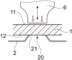
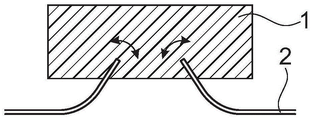
According to one aspect of the invention, there is provided a method of mechanically securing a first object (1) to a second object (2), the first object comprising a thermoplastic material in a solid state, the second object having a substantially planar sheet portion with a perforation (20) along which the sheet portion has a rim (21), wherein the first object is positioned relative to the second object such that the rim is in contact with the thermoplastic material, and wherein mechanical vibrational energy is coupled into the assembly comprising the first object and the second object until a flow portion of the thermoplastic material becomes flowable due to frictional heat generated between the rim and the thermoplastic material and flows around the rim to at least partially embed the rim within the thermoplastic material. After the mechanical vibration ceases, re-solidifying the thermoplastic material, whereby the re-solidified thermoplastic material at least partially embedded in the rim anchors the first object into the second object.
Description
Technical Field
The invention relates to the field of mechanical engineering and manufacturing, in particular to mechanical manufacturing such as automobile engineering, aircraft manufacturing, railway engineering, shipbuilding, machine manufacturing, toy manufacturing, constructional engineering and the like. And more particularly to a method of mechanically securing a second object to a first object.
Background
In the automotive, aerospace and other industries, there has been a trend to move away from steel-only structures and to use lightweight materials such as aluminum or magnesium metal sheets or polymers, such as carbon or glass fiber reinforced polymers or unreinforced polymers, e.g. polyesters, polycarbonates and the like instead.
New materials pose new challenges in bonding elements of these materials to, in particular, bonding a flat object to another object. One example of this is to bond a part of a polymer-based material to a metal part, such as a metal sheet.
To meet these challenges, automotive, aerospace, and other projects have begun to employ substantial amounts of adhesives. The adhesive is light and strong but has the disadvantage that it is not possible to control the stability over a long period of time, since degraded adhesives are almost impossible to detect without completely releasing the adhesive, for example due to brittle bonding. Also adhesives can lead to increased processing costs both because of the material costs and because of delays in the processing due to slow hardening processes, especially if the surfaces to be connected to one another have a certain roughness and thus a fast hardening thin-layer adhesive cannot be used. In addition, a flat adhesive between two objects that do not have the same coefficient of thermal expansion can lead to additional stability problems because the adhesive is subject to a large amount of shear force on a daily basis due to temperature oscillations.
One particular challenge in joining components to one another is tolerance compensation, for example if the components are joined to one another using other joints that are not adhesively joined, for example by screws and nuts or by pins. In this connection, it is desirable to precisely define the relative position of the fastener to the respective fastening location. This precise definition is particularly difficult to achieve if the machining process has to be particularly economical and/or if the parts to be joined are relatively large in at least one dimension and/or react to the conditions to which they are subjected during the machining process and are used in different ways, for example if they have different coefficients of thermal expansion.
Disclosure of Invention
It is therefore an object of the present invention to provide a method of mechanically securing a second object to a first object which overcomes the disadvantages of the prior art methods. The object of the invention is, in particular, to provide an economical method for producing a reliable connection between a thermoplastic component and a non-liquefiable component in the liquefied condition of the thermoplastic component, or to produce a reliable connection between different components by means of thermoplastic connecting elements. Another object of the invention is to provide a method for forming a reliable connection between components that is efficient and quick. Another object of the invention is to provide a method of forming a reliable connection between components and allowing effective tolerance compensation.
According to one aspect of the present invention, there is provided a method of mechanically securing a first object to a second object, the method comprising the steps of:
-providing a first object comprising a thermoplastic material in a solid state;
-providing a second object having a substantially flat sheet portion with an edge;
-positioning the first object relative to the second object such that the rim is in contact with the thermoplastic material;
-coupling mechanical vibrational energy into the assembly comprising the first object and the second object until the flowing portion of the thermoplastic material becomes flowable due to frictional heat generated between the rim and the thermoplastic material and flows around the rim to at least partially embed the rim within the thermoplastic material;
-stopping the mechanical vibration and causing the thermoplastic material to re-solidify, whereby the re-solidified thermoplastic material at least partially embedded in the rim anchors the first object in the second object.
In the step of coupling mechanical vibrational energy into the assembly, the first object may be pressed against the rim such that when the flow portion liquefies, the rim is pressed into the thermoplastic material of the first object.
After stopping the mechanical vibrations, the pressure in the embodiment is maintained until the flow portion has re-solidified at least to some extent to prevent the rebound effect.
In an embodiment, the second object is provided as a perforation with a tab portion, wherein the rim extends along the perforation.
In an embodiment with a perforation, the sheet portion around the perforation has a protruding section protruding away from the sheet plane, i.e. protruding proximally, towards the first object, if vibrations are coupled into the first object.
The first object and the connection to the second object may in embodiments be for example sealing a perforation, i.e. sealing a proximal region of the second object from a distal region thereof. The first object may thus for example have a continuous body extending into a periphery, which periphery is embedded in the rim.
In other embodiments, the first object has a through opening, in which for example a connector or a non-liquefiable body described below can be arranged, which forms an anchor for another object. It may, for example, have threads or other engagement features, and/or it may be used with a nut and pin arrangement extending therethrough. Alternatively, the bearing sleeve, ball bearing or other bearing may be positioned within the first object, in particular within the through opening of the first object.
In particular, mechanical vibrational energy may be coupled into the first object but not (directly, i.e. at least through the first object) into the second object. In particular, in the positioning step, the first object is usually brought into contact with the second object from a proximal side, and the step of coupling energy into the first object may comprise pressing a vibrating sonotrode against a proximally facing coupling face of the first object, whereby both a pressure force with respect to the second object and a mechanical vibration are coupled into the first object by the sonotrode.
In order to exert a counter force to the pressure, the second object is then placed against a support, for example a non-vibrating support. In an embodiment, the second object is placed against the support without an elastic or yielding element between the support and the second object, so that the support rigidly supports the second object.
However, the pressure applied during this process may be low enough to enable the second object to be self-supporting. In general, the manner according to the invention gives very good energy absorption properties of the edge in physical contact with the thermoplastic object (as an inherent energy director for mechanical vibration energy), the thermoplastic material and/or the edge being subjected to mechanical vibrations, so that it has been possible to apply only a small pressure. This may be a significant advantage for applications where at least one object has a complex shape and/or is part of a complex item, such as a car body, and thus places the rigidly supported support at a lateral position where it is difficult to apply force.
It is nevertheless not excluded to couple energy into the second object, i.e. to apply mechanical vibration energy from the side of the second object.
In particular, but not exclusively, in embodiments involving coupling vibrations into the second object, the vibrations may be transverse vibrations, whereas in other embodiments the vibrations may be longitudinal vibrations. Arrangements with transverse vibrations are known, for example, from the welding of metal parts. To this end, for example, the following options exist:
the sonotrode typically couples vibrations into the second object from the side edges (if defined, in an in-plane direction with respect to the sheet plane of the second object), whereas a separate pressing tool applies the required pressure between the first and second object.
The sonotrode itself generates transverse vibrations at the distal end coupled to the second object. Thus, the mechanical coupling between the sonotrode and the second object may enable this lateral movement to be transferred to the second object. For example, the second object comprises, in addition to the anchoring plate comprising (e.g. constituting) the tab portion, a fastening element which can be coupled to the sonotrode. In particular in embodiments, the second object is a fastening element configured to fasten another object to the first object, the fastening element having a corresponding mechanism, for example by being a threaded bolt (internal and/or external thread), a non-threaded rod, a pin, a nut, a hook, an eyelet, a base for a bayonet coupling, or the like.
The invention also relates to a set of sonotrodes and a set of second objects adapted thereto for carrying out a process according to any embodiment of the invention comprising coupling mechanical vibrations into the second objects. For example, the second object may comprise an anchor plate and a fastening element bonded thereto, and the sonotrode may comprise a distal coupling output face shaped to be in contact with the anchor plate to transmit forces and vibrations, and a receiving structure for receiving the fastening element. The receiving structure, such as a receiving opening or a protrusion, may be adapted for mechanical engagement to a fastening structure (thread or the like) of the fastening element.
Alternatively, other energy may be coupled into the assembly in addition to mechanical vibration energy. In one example, the second object may be preheated by infrared radiation, induction (particularly effective near the edge), hot air flow, or the like. Additionally or alternatively, the thermoplastic material may be locally preheated proximate the interface of the rim, such as by electromagnetic heating as described in Swiss patent application 01104/15, by radiation, or the like. For example, for the electromagnetic heating described in Swiss patent application 01104/15, the thermoplastic material located in the attachment zone may be provided with electromagnetic doping.
In both cases, this preheating assists the process of directly or indirectly making the thermoplastic material flowable. If the preheating step is such that the absorption of mechanical vibration energy is increased at or near the location where the preheating step acts, an indirect effect is obtained, in particular due to increased internal friction caused by increased temperature.
The purpose of this additional energy is to increase the speed and/or reduce the required pressure. This also has a positive effect on process control.
The flowing portion of the thermoplastic material is the portion of the thermoplastic material that is in the process and is caused to liquefy and flow due to the influence of mechanical vibrations. The flow portions need not be one piece, but may comprise separate parts from each other.
The liquefaction of the flow portion is here mainly due to friction between the vibrating part (e.g. the first object) and the non-vibrating part (e.g. the second object) of the assembly, which directly or indirectly heats the thermoplastic material of the first object. This is particularly effective if the friction that generates heat occurs where the material is to flow, as opposed to other methods involving liquefied thermoplastic material, where there is no cooling effect where the flow portion has flowed away from the heat source. In particular in the step of causing the flow portion of the thermoplastic material to become flowable, the flow portion or a component thereof becomes flowable due to heat generated between the protruding section and the thermoplastic material. In an embodiment, the second object is fixed to the first object as a result of the above-described method steps, wherein the space on the other side of the second object than the side of the first object in contact therewith (distal in an embodiment of the type described above, wherein vibrational energy is typically coupled into the first object from the distal side) is empty along the edges (and thus along the perforations, if available) so that the thermoplastic material can immediately flow along the surface of the sheet portion of the second object. In particular, no other object located distally of the second object is fixed to the second object by the first object in embodiments.
In an embodiment, a tab portion along an edge (and thus surrounding a perforation if applicable) is deformed such that the tab portion protrudes away from a defined tab plane. In particular, the sheet may protrude towards the first object side (towards the proximal side in embodiments of the kind described above, wherein the vibrational energy is typically coupled into the first object from the proximal side).
In particular, the protruding section (if present) which is the deformation section may be the same metal sheet as the sheet section.
In this context, the term "sheet plane" means a plane/surface generally defined by the shape of the generally planar sheet portion in the region around the rim, and particularly around the perforation (if present). The sheet plane may be a plane in the sense that it extends directly in two directions. Alternatively, the sheet portion may be bent and thus formed into a more complex 3D shape, for example if it constitutes a surface of a complex object, such as the body of an automobile or aircraft. In the example where the second object is deformed near the edge to protrude away from the sheet plane, the curvature of the second object at the location from which the deformed section extends is often much greater than the curvature of the sheet plane.
This deformed section may be formed by deforming a corresponding portion of the tab portion, such as by making a cut (e.g., by stamping) and bending or otherwise deforming thus opening the second element where the corresponding part of the tab portion is initially located. Here, the deformation section may still be in one piece with the sheet.
As an alternative to the deformation section, it is also possible to provide the section of the sheet portion protruding away from the sheet plane as a separate element fixed to the sheet material, for example by welding.
As a further alternative to a deformed section, a section protruding towards the side in contact with the first object may be manufactured by a forming process from the beginning, which section ends at an edge, for example by die casting or pressing or injection moulding if said section is ceramic (followed by well-known subsequent processing steps). In this embodiment, the sheet portion may even be constituted by a portion protruding towards the first object and/or a section embedded in the flow portion after the process, i.e. without having a sheet plane further defined by the sheet portion.
In embodiments with a perforation and with a protruding (e.g. deformed) section around the perforation, the deformed section may be symmetrical, i.e. evenly deformable around the perforation (this includes the possibility that the deformed section has rough edges, e.g. with a saw tooth like shape). In particular, it is rotationally symmetric with respect to an axis perpendicular to the sheet plane passing through the centre of the perforation.
Alternatively, it may be rotationally asymmetric about the axis, with the height of the protruding section varying as a function of position along the edge. In this embodiment, the symmetry may be the case if the protruding section does not extend all along the perforation but along a certain section of the rim without this protruding section. In this case, however, the protruding section may extend at least around more than 180% of the periphery, thereby locking the first and second objects to each other with respect to relative forces in all planes.
In a set of embodiments with a second object comprising a perforation extending along the edge, the sonotrode and the first object may be adapted to each other such that the coupling face (a part of the surface of the first object against which the sonotrode is pressed) covers the in-plane position of the edge but cannot extend to a central position relative to the perforation. By "in-plane-of-coverage position" is meant herein that within the projection along the proximal-distal axis, the rim is located in the region of the coupling surface.
For example, the coupling faces may form tracks around the center, with a central in-plane location corresponding to the in-plane location of the perforations.
Thus, one or a combination of the following options may be implemented:
the sonotrode comprises a central recess with a coupling face surrounding the central recess; and/or
The first object has a proximally directed central recess with a coupling surface surrounding the central recess.
The effect of the coupling surface not extending to a central position may include making process control easier and/or preventing the central position of the first object (e.g. with a functional element) from being damaged.
In a set of embodiments comprising a perforation of the second object and a protruding section around the perforation, the protruding proximally facing protruding section faces the first object, which may be provided with distally facing spacers (also referred to herein as "feet"). This space may be arranged laterally of the position where the contact side of the first object is in contact with the edge of the second object.
In particular, the space may be arranged more laterally than the protruding section of the second object, whereby, when the first and second objects are pressed towards each other, when a vibration is applied, a relative movement of the first and second objects towards each other may be caused until the foot abuts the sheet portion at a position defining a sheet plane. Thus, the z-position of the first object relative to the second object may be defined by the dimensions of the foot acting as a spacer.
Thus, this foot is an example of a relatively simple measurement that accomplishes z-position control without complex measurement tools. In particular, the foot performs a good process control, wherein at the end of the process the operator gets physical feedback when the correct z-position has been reached. It is advantageous if the process is carried out manually or, likewise, if mechanical resistance is a control parameter in an automated process. Other methods for precisely controlling the z position are discussed below.
The method may comprise the further step of machining a bore in the second body, e.g. by punching, drilling etc., prior to the positioning step. Alternatively, the perforations along which the rim is formed may in embodiments be openings which are anyway present in the second body or which have been provided during processing.
The first object comprises a thermoplastic material. In an embodiment, the first object is made of a thermoplastic material. In other embodiments, the first object comprises a body of non-liquefiable material in addition to the thermoplastic material. The body of non-liquefiable material may constitute a reinforcing portion of the first object.
In embodiments with a non-liquefiable body, the body of non-liquefiable material is different from a filling which is merely a mass of particles, but has a defined position and orientation and is an enlarged body of large size. In the plane of the sheet defined by the second object, this dimension may for example be 10% of the average diameter of the first object (of the cross-section perpendicular to the axis of insertion) or, if applicable, 10% of the average diameter of the perforations, and/or the characteristic dimension may be at least 0.1mm in any direction. In particular, the body may be metallic or ceramic. In particular, the body may be, for example, of a defined shape and thereby provide increased rigidity to the first object. By means of the body, the first object is confined within at least two spatially separated regions, namely a body region and a thermoplastic region.
In embodiments where the first object comprises a non-liquefiable material in addition to the thermoplastic material, the thermoplastic material may be arranged at least on the part of the surface that is in contact with the rim.
The first object may comprise a fixation element for fastening the further object to the second object. For example, the first object itself may secure elements (fasteners) thereto by including suitable structure, such as threads or other suitable structure, or it may include dedicated securing elements, such as threaded rods, nuts, or the like. In these embodiments, the first object may be shown as a fastener (or anchor) for another object. In an alternative embodiment, the first object itself may constitute an object having a function other than just a fastener.
In particular, but not exclusively, in these alternative embodiments, the first object may be relatively large, making it impossible to vibrate the entire first object to attach the first object at multiple attachment sites simultaneously. In this embodiment, it is necessary to simultaneously cause multiple sonotrodes to act to secure the first object to the second object at a corresponding plurality of attachment sites, and/or it is advantageous to have sufficient flexibility to adequately decouple portions of the first object from other portions of the first object at the sites where attachment occurs. Examples of such cases are discussed below, for example with reference to attachment flanges.
In an embodiment, the first object has an attachment area with a thermoplastic portion and further has a functional area different from the attachment area. This functional region may, for example, comprise fastening structures and/or other fastening elements. This functional area may be configured such that it is not possible and/or desirable to locally liquefy the thermoplastic material that will embed the rim in the process. In many embodiments, the first object located within the functional zone may contain a liquefiable material, but the function will be adversely affected by the process according to the invention.
In an embodiment, the first object is processed in a process comprising the step of two-shot injection moulding, the attachment zone being of one thermoplastic material and the functional zone comprising another thermoplastic material. Next (or also in other cases with a first object comprising a thermoplastic material part) the thermoplastic material of the different zones has different material properties.
The modulus of elasticity E of the thermoplastic material of the functional region is greater, for example much greater, than the corresponding modulus of the attachment region; and/or
The (elastic) extensibility of the thermoplastic material of the attachment zone is much greater than the extensibility of the functional zone. Thus, the thermoplastic material of the attachment zone may alternatively be an elastic thermoplastic material, such as thermoplastic polyurethane. Whereby it is suitable for repeated heating/cooling cycles. According to another option, the thermoplastic material of the attachment zone may be a partially crystalline polymer (e.g. polypropylene) with a relatively low glass transition temperature and a relatively high plasticity at elevated temperatures, by a one-shot plastic deformation (creep) process to compensate for thermal distortion, e.g. during electrodeposition.
By means of which the different thermal expansion behavior between the first and second object can be compensated.
In embodiments comprising at least one attachment area, the material of the attachment area(s) may be fixed to the first object body (enveloping the functional area (s)) by a form-fit connection. For example, the first object body may comprise at least one undercut opening, and the thermoplastic material forming the attachment zone(s) may be at least partially present within the undercut opening(s). Additionally or alternatively, the body may comprise an open porous section, with the thermoplastic material infiltrated with the attachment region(s) of the porous section. In addition or instead of a form-fit connection, other types of mechanical connections, for example adhesive connections, may also be present between the material of the attachment zone and the body.
In one set of embodiments, the first object comprises a main body defining a functional zone and a flange (attachment flange) extending at least along a part of the lateral periphery of the main body and defining an attachment zone, whereby at least part of the flange is clamped between the sonotrode acting in the axial direction and the second object in the step of coupling mechanical vibrational energy into the assembly.
The attachment flange may be a peripheral, laterally protruding portion of the first object. It may be constructed of a thermoplastic material; at least the distal face comprises a thermoplastic material. It may for example define a proximally facing coupling-in surface for a sonotrode, which is at least approximately parallel to the distal surface of the first object, the latter being in contact with the edge of the second object. Thereby, even if the first object has, due to its function, a complex shape which may be different from the shape with a flat distal surface, a less complex shape becomes possible at the attachment site(s).
The first object, in particular its attachment flange, may comprise a well-defined, possibly proximally-directed marking, coupling surface portion which is positioned to correspond to the attachment site defined by the second object, for example its perforation along which the rim extends. This coupling surface portion may, for example, be parallel to a corresponding distally facing surface portion on the opposite side, which is in contact with the edge of the second object.
Also, the first object may comprise a resilient connection between the attachment flange (or other attachment structure having a coupling surface and a surface portion in contact with the rim) and the first object body. Thereby, the attachment structure (e.g. attachment flange) may be vibration decoupled from the other parts of the first object.
This is an option especially in embodiments where the first object is relatively large and where it is not possible to couple vibrations into the entire first object or where it is disadvantageous to do so. In this embodiment, the attachment at different attachment sites or for many attachment sites must be carried out simultaneously, in which case several sonotrodes must act simultaneously. Instead of sequential attachment at different attachment sites. In turn, some flexibility of the first and/or second object is required, since the attachment process causes relative movement of the first and second objects at the actual attachment site, however this movement is not present at other attachment sites. Attachment flanges and/or attachment structures that are separated from the body by a joint may provide this flexibility.
In one set of embodiments, the method includes the further step of providing the first and second objects to the connector initially separated from each other. In these embodiments, the assembly into which mechanical vibration energy is coupled also includes a connecting member. The connecting element may be caused to become at least partially embedded in the thermoplastic material of the first object during the process and anchored with respect to the first and second objects after re-solidification. In embodiments, as described in more detail below, the connector may be connected to the first object at a plurality of possible relative positions (by embedding or by another connection), for example to compensate for dimensional and/or positional deformations during machining.
In particular, in the step of coupling mechanical vibration energy into the assembly, the vibrating ultrasonic welding tool may be pressed against the coupling surface of the coupling piece when the coupling piece is pressed against the first object until the thermoplastic material of the first object becomes flowable at the edge of the coupling piece so that the coupling piece is driven into the first object. Simultaneously and/or sequentially, mechanical vibration energy may also be absorbed at the interface of the second object and the first object.
The attachment means may here be caused to extend through the plane defined by the rim of the tab portion and thus from its proximal side, if applicable, by the entrance of the perforation. Similarly, in the case of a body of non-liquefiable material (such as a reinforced portion) of the first object, the body may be arranged to extend through a plane defined by the rim (if applicable defined by the perforated inlet). More specifically, in embodiments where the second object has a through-hole, the connector/body may extend through the through-hole.
Connectors of the type in question may be constructed of a material that is not liquefiable. Alternatively, it may comprise a thermoplastic material. In one example, it comprises a thermoplastic material capable of being welded to the thermoplastic material of the first object; it may be the same thermoplastic material or at least a polymer material comprising the same matrix.
Connectors of the type in question may have one or a combination of the following functions:
the connection piece may form, together with the thermoplastic material, an interface where absorption of vibrational energy takes place. Thus, the connection provides additional means to control the energy absorption and thus the flow of the thermoplastic material.
The shape of the connection piece may be designed to restrict the flow of the thermoplastic material, in particular inwardly with respect to the axial direction, in particular causing a more pronounced flow of the material around the second object in the vicinity of the rim, in particular over the distal side thereof.
The connecting piece can have further functional elements, such as connecting parts, flanges, etc. Generally, the considerations applied herein to the shape and function of the connector also apply to the body of non-liquefiable material that is part of the first object (this body may be shown as a pre-mounted connector).
The body of non-liquefiable material of the first object or the connecting piece may carry structures for other functions, such as screws, other mechanical connections, contacts or leads, etc.
Regardless of whether a body or connector is present, in one set of embodiments, the method includes attaching a first object to a metal part forming part of the vehicle body.
In an embodiment, the body or the connector respectively has a surface provided with at least one retaining feature on a lateral surface portion, which retaining feature cooperates with the thermoplastic material of the body to stabilize the relative position of the body within the embedded thermoplastic material.
The invention also relates to a connection having the characteristics defined herein. The invention also relates to a kit of at least one connector and a first object and/or a sonotrode.
Furthermore, the invention relates to a connecting element, which is, or forms part of, a first object according to any of the embodiments described herein. The invention also relates to a fastener, which is the second object described herein and comprises a fastening element.
In one set of embodiments, the first object comprises a structured contact side of thermoplastic material, which is the side of the first object that is in contact with the rim for fixation. The fact that the contact side is structured means that it is not just flat uniform and even that it comprises protrusions/recesses. For example, it comprises a pattern of ridges and grooves, for example a regular pattern.
It has been found that the structured contact side has the effect that the required input of energy and force is reduced until the rim has penetrated into the thermoplastic material of the first object to a sufficient depth. In particular, such required input may reduce more than one scaling factor corresponding to the unfilled recess volume portions. This is due to the additional flow channels created by the structure.
In one embodiment, the structure forms a pattern of radially extending ridges/grooves.
In which the sheet portion of the second object has a protruding section protruding away from the sheet plane towards the contact side, the depth of the notch may be selected to be smaller than the height of the protruding section.
Another set of embodiments also addresses the problem of reducing the required force and/or energy input. In this further set of embodiments, the second object comprises a plurality of, for example, smaller peripheral perforations arranged around, for example, a larger main perforation.
The peripheral perforations may especially be arranged in sections of the second object protruding away from the second object sheet plane towards the contact side, i.e. the peripheral perforations may be arranged at positions of the sheet material inclined with respect to the sheet plane.
This peripheral perforation has the effect of increasing the footprint of the connection, providing additional security to the rotation, and reducing drag in the process by providing additional flow channels.
With reference to the above discussed set of embodiments, it is especially desirable to reduce the energy and force input if the materials involved are proprietary and/or if the method is carried out at a relatively advanced stage of processing complex objects. For example, in embodiments where the second object may comprise a sheet metal painted part/drawing, and the painted part/drawing may be damaged. The approach according to these embodiment groups may be advantageous in this case.
In many embodiments, if the method comprises pressing the first object against the second object when vibrations are coupled in particular into the first object, a reaction force to the pressing force is generated by holding the second object in a position different from the pressing position of the first object, e.g. a mounting frame, or by making the second object part of a complex, rather heavy object located on the ground. Then the reaction force is then dependent on the stiffness of the second object. If desired, special supports may be employed to assist.
In one set of embodiments, a dedicated anvil structure is employed in addition to the second object. The anvil of this construction may be placed distal to the second object and it may have at least one of the following functions:
-the anvil directing the flow and resolidification of the flowable thermoplastic material. Thereby, the overall stability of the connection between the first and second object is enhanced after this process, and this ultimately reduces the required penetration depth. Thus, using the same anvil may be one method for reducing the required force and energy input.
The anvil may also support the second object and avoid undesired deformation thereof if, for example, the second object is relatively thin or weak.
This anvil is different from being just flat. In particular it may comprise a guiding protrusion located outside the rim (inside with respect to the centre of the perforation if the rim extends along the perforation) and a notch located distally of the rim (and radially outwards from the rim if the rim extends along the perforation) to guide the flow "below" (distal) the rim and the second body portion adjacent the rim.
The volume of this recess can in particular be smaller than the volume of the available thermoplastic material which becomes flowable, so that if the vibration input is kept sufficiently long, the volume of the flow section is larger than the volume of the recess. Thereby, a sufficient forming pressure can be created in the process, whereby the filling of the recess by the flow portion is controllable and predictable.
In one set of embodiments, the method includes adjusting the position of the first object and/or the sonotrode relative to the second object. This especially pertains to x-y (in-plane) positions. For this reason, there are two basic configurations:
in a first basic configuration, the x-y position of the sonotrode relative to the second object is defined, for example by a mounting frame, the adjusting step comprising adjusting the position of the first object arranged between the sonotrode and the second object relative to the sonotrode and the second object.
In a second basic configuration, the operator employs means for defining the position of the first object relative to the sonotrode, the adjusting step comprising adjusting the position of the first object-sonotrode assembly relative to the second object.
According to a first basic configuration, the means for adjusting the position of the first object with respect to the sonotrode and the second object (support or the like) are configured independently of the sonotrode. Next, the operator must confirm that the mechanical vibration can be coupled into the first object. Thus, according to a first option, the shape of the guiding means for this purpose is adapted to the shape of the first object in such a way that only the lateral position is precisely defined, but with a certain degree of freedom with respect to movements in the axial direction (for longitudinal vibrations coupled into the first object). According to a second option, which can be combined with the first option, the guiding means comprise a spring, whereby the first object is only loosely coupled to any mounting frame.
According to a second basic configuration, the sonotrode and the second object can be adapted to each other to define a laterally relative position. For example:
the sonotrode may comprise a guide protrusion cooperating with a guide recess of the first object, or vice versa. Optionally, this guiding protrusion/guiding recess (or other guiding means) is different from rotational symmetry to prevent any rotation of the first object with respect to the sonotrode.
The sonotrode may comprise a peripheral flange surrounding the first object to define its position.
The sonotrode may comprise at least one penetration guide (spike or the like) that penetrates into the material of the first object during the process.
It is also possible to temporarily fix the first object to the sonotrode, for example by means of screws or the like.
Additionally or alternatively, other means may be used to temporarily join the first object to the sonotrode, such as a vacuum means between the sonotrode and the first object, for example by means of a suction channel through the sonotrode.
Additionally or alternatively, a separate guide may be employed. This separate guide may be laterally guided both with respect to the sonotrode and with respect to the first object. In particular, it can be guided relatively loosely with respect to the sonotrode so that vibrations are not coupled into the guide. This guide may be a cylindrical element guided in aligned openings of the first object and the sonotrode, which openings conform to the cross section of the guide. Especially in embodiments where the guide is also loosely guided relative to the first object, additional axial support may be provided to prevent the guide from loosening from the assembly.
The cylindrical shape of this guide may, but need not, be a rotating cylinder, if available.
Additionally or even further alternatively, a pressing tool is used which is different from the sonotrode but additionally used thereon. This pressing tool is used to press the first object against the second object at least in an initial stage of the step of coupling mechanical vibration energy into the assembly. The problem is solved by this pressing tool in that the sonotrode does not exert any force on the first object when longitudinal vibrations are coupled from the sonotrode into the first object, wherein the sonotrode is pressed against the first object, approximately in half a wave form of each oscillation cycle. Without any lateral guides (such as described above), this may cause a runaway, the first object being "unfixed" relative to the second object. The additional pressing means may ensure that the first object is pressed towards the second object. This additional pressing tool may comprise a guide structure, such as a peripheral flange, defining the lateral position of the first object with respect to the guide tool.
The measure according to the invention has the essential feature that the attachment site defined by the edge, which is embedded in the flow portion in the process, does not have a precisely defined position, a precise positioning of the first object relative to the second object being desired and achievable.
More specifically, for the change in the relative position of the attachment site and the first object, the following statement may be used to accomplish:
the lateral (x-y) variation depends strongly on the lateral extension of the first object or its attachment area, respectively. For relatively small attachment areas (e.g., relatively small perforations), they may be, for example, between 0.1mm and 5 mm. For larger attachment areas (e.g., larger perforations), they may be scaled to larger values.
-if the first object has a flat distally facing surface, the axial (z-) variation depends on the distance by which the section of the second object protrudes towards the first object. It may vary between 0.1mm and 2mm to obtain a relatively small height of the protruding section, and may be larger for larger sizes.
Depending on the distance separating the different attachment points, or more generally depending on the lateral extension of the attachment zone, angular variations of up to 10 ° to 20 ° can be compensated for.
In many embodiments, the restriction given is that around the attachment zone, the thermoplastic part not belonging to the flow part should remain. The thickness of this non-liquefying region is, for example, at least 1mm in all directions.
On the basis of this fact, the approach according to the invention can be used for tolerance compensation, for example using the following method:
step 1: tolerance mismatches are measured, for example, visually and compared using CAD data.
Step 2: the correct position x, y, z angle is calculated.
And step 3: the first and second objects are positioned relative to each other within the calculated correct position x, y, z angle (minus the z offset that takes into account the relative motion of the first and second objects during the next step 4).
And 4, step 4: implementing a method according to any of the contents and/or embodiments described herein until a correctly calculated position has been reached.
Optionally, the softness of the structure can be corrected by an external distance measuring system coupled to the means for applying the vibration energy, which correction system is adapted to the tip z-position, if necessary.
In embodiments, additionally or alternatively to this, further measures to compensate for z variations may be employed. By this measure, the range of the z-variation described above (e.g. between 0.1mm and 2 mm) can be exceeded, for example, and this measure also makes it possible to perform different types of control of the compensation of the z-variation.
Such additional measures include:
providing an anchoring part and an adjustment part, wherein at least the anchoring part belongs to (and in embodiments may consist of) the first object.
Adjusting the z-position of the adjustment member relative to the anchoring member; and
when the adjustment member is in the adjusted position, its position relative to the anchor member is fixed.
The z-direction may be a direction perpendicular to a sheet plane defined by the second object located at the edge of the attachment site. Alternatively, the z-axis may be defined as the axis on which the pressing force acts during the step of applying the mechanical vibration for embedding the rim, for example if this plane is not defined.
The following options may be implemented:
the fixing step may cause the adjustment member to be non-detachably fixed with respect to the anchoring member. For example, the securing step and/or the adjusting step may include applying mechanical vibration to the assembly of the anchoring member and the adjusting member to cause the thermoplastic material of at least one of the members to become flowable to secure after the members are re-solidified with one another.
This fixing of the parts to each other after re-solidification can be caused according to a first option by the material of the objects being fused together (for example in a fusion), or alternatively because the anchoring part and the adjustment part are in one piece, with a transfer zone (collapse zone, extension zone) located between them that is deformable when the thermoplastic material is flowable (flowable here including "pasty", plastic deformation caused by moderate force input).
According to a second option, the parts can be fixed to each other, wherein one part comprises a liquefiable material (in particular a thermoplastic material) and the other part comprises a structure that can be infiltrated by the liquefiable material, whereby a form-fitting connection is formed between the parts after re-solidification.
Additionally or alternatively, the components may be secured to each other by an adhesive connection between the re-solidified material and the other material to which it is adhered.
The adjusting and fixing steps may be combined in a single step process. For example, they may be implemented by a vibrating sonotrode which presses the parts against each other and, after the material has become flowable, moves the parts relative to each other until the desired z-position has been reached, while stopping the movement and energy input (which may, depending on the configuration, have been stopped for a while before the desired position has been reached). After re-solidification, the re-solidified flowable material fixes the relative position. Optionally, the bearing force may be maintained during re-curing.
Alternatively, the adjusting step may be carried out before the fixing step. Next, for embodiments comprising fixation by input of mechanical vibration energy, the anchoring member and the adjustment member may be configured such that their relative z-position is temporarily locked, so that the engaging action of mechanical vibration and pressure does not change the relative z-position. For example, the anchoring member and the adjustment member may have a threaded portion mating such that the adjustment member may be threaded onto the anchoring member. Other configurations may be used for this temporary locking. As an alternative to this temporary locking, the mechanical vibration may be coupled into the component from a direction that is not parallel to the z-axis, but, for example, substantially perpendicular to the z-axis.
For example, measurement data may initially be obtained regarding details of the second object (or a component comprising the second object) and/or details of any other component (the first object, other object to be fixed to the first object). Based on this, the desired z adjustment can be pre-calculated.
The alternative of adjusting before fixing can be used for the separation step in the process. The production line next comprises an adjustment station and a fixing (fastening) station. In particular, this may be advantageous if the second object is relatively large or belongs to a relatively large pre-assembly (e.g. a car body), since the z-adjustment step may then be carried out at a smaller station and does not delay the main process.
The adjustment member may be a connector or a body of the type described above.
Alternatively, the anchoring member may comprise a connector or a body of the type described above, the adjustment member being selectively another object, i.e. configured to be fixed in an adjustable position relative to the connector/body.
According to another embodiment, both the adjustment part and the anchoring part comprise a thermoplastic material and the adjustment part and the anchoring part are welded to each other.
As a further embodiment, the anchoring part and the adjustment part are in one piece, but with a collapse or extension zone between them, which is activated by energy input.
If the anchor part and the adjustment part are not one piece, the method may comprise positioning the adjustment part relative to the anchor part before the adjusting step.
The adjusting step may be carried out after and/or simultaneously with the step of fixing the first object to the second object.
These possibilities can be combined arbitrarily, unless otherwise specified.
In embodiments comprising fixation and/or adjustment by mechanical vibrational energy input, the fixation and/or adjustment may be implemented according to a first option together with fixation of the first object to the second object. Alternatively, positioning and/or adjusting the components relative to each other may be performed after fixation. As yet another alternative, as described above and discussed in greater detail below, securing and/or adjusting the components relative to each other may be performed prior to fastening.
In any case, optionally, the step of coupling mechanical vibration energy into the assembly for securing the edge of the embedded second object and the step of coupling mechanical vibration energy into the assembly for securing and/or adjusting may comprise pressing the vibrating sonotrode against the assembly in a direction not perpendicular to the z-axis but, for example, in a direction parallel to the z-axis or at an angle thereto.
In a first subgroup, which complements this option, the pressure applied for fastening and for fixing/adjusting has the same direction. In the second subgroup, they have opposite directions.
In any case, during the step of coupling energy into the assembly and pressing the vibrating ultrasonic weld pressure against the coupling surface to secure the first object to the second object, portions of the second object may define stop surfaces for movement of the first object relative to the second object during securing. After the first object has come into contact with the stop surface, the mechanical resistance against further movement increases considerably. Thereby the relative position of the first and second object is defined and will remain defined when pressure and mechanical vibrations are subsequently coupled into the assembly to fix and/or adjust.
This stop surface may for example be bounded by a flat part of the second object surrounding the attachment point/attachment points.
The above-described methods of adjustment and fixation at an adjustment position may be implemented in embodiments of the herein described aspects of the invention. But it can also be implemented independently thereof.
The invention also relates to a device comprising the anchoring means and the adjustment means described with reference to any embodiment of the method mentioned herein.
In one set of embodiments with or without the step of adjusting the z-position, the second object comprises an extended opening (unlike a perforation along which the edge caused to embed the thermoplastic material extends). The first object (and/or the attachment member secured thereto) may then extend through the entrance of the opening. Thereby, there is more space and in particular a deeper depth, respectively, available for the first object and/or the functional part of the connecting element.
The second object need not protrude along the extended opening towards the side of the first object and need not have any other shape that is particularly suitable for the fixing/fastening step. Also, the size of the functional component/connector may be chosen because of the available space for the extension opening.
In this set of embodiments, the first object has an extension extending through the entrance of the extension opening.
The connector may be configured to also extend through the entrance of the opening and will be fixed relative to this extension. In particular, the connecting element can be fixed at different depths, in particular it is an adjusting element with a relative z-position in the above sense. Also, the movement of the connector into the extension portion need not be collinear with the movement during securement, such that adjusting the z position includes adjusting the z 'position having a z' axis at an angle to the z axis. In summary, the parameters that can be used to fix the connection piece relative to the first object become independent of the anchoring process due to the extended opening.
In some embodiments that include an extended opening and a connector, the connector is configured for securing another object thereto. Thus, a coupling element may be provided to fix a further object, in particular if the further object has a relatively large extension in both in-plane directions. For example, in this embodiment, the further object may be clamped between the connector and the head of the coupling element.
A joining element of this type can, for example, be clamped or screwed to the connecting piece or fixed by a bayonet coupling or the like or by a material connection (adhesive connection, welded connection, fusion, etc.).
Also in this set of embodiments the size of the extension opening is at least larger than one in-plane dimension of the extension part, whereby x-y position adjustment of the functional part and/or the connecting piece with respect to the second object is made possible.
In an embodiment, the extension part comprises a tube part extending into the opening, whereby the connection piece can be placed at least partially inside the tube part.
Embodiments of the second object comprising an extended opening may comprise a plurality of perforations of the type discussed above, in particular perforations around which the second object has a side towards the first object (proximal if vibrations are coupled into the first object, distal if vibrations are coupled into the second object). Such perforations may in particular be distributed around the periphery of the extension opening.
In this embodiment or other embodiments having a plurality of perforations, the first object may be of a type that includes, inter alia, an attachment area (e.g., an attachment area for each perforation) and a functional area. In particular, the first object may be a dimensionally stable material, such as a metal, a mixture, a ceramic, etc., except for the attachment zone(s) comprising a thermoplastic material.
The embodiment comprising an extended opening is particularly suitable for arrangements in which the second object, the first object and/or, if available, further objects are not plane in the sense of extending directly in two directions but have a complex 3D shape. This is because the extension opening provides an additional degree of freedom for the connection, in particular with a connector, which may be an extension into space and to a direction that is not limited by the geometry of the location where fastening occurs (e.g. around a perforation of the type described above).
In an alternative embodiment, the first object may have a perforation that extends into the second object and through the plane of the sheet (if defined) if the dimensions allow this. No separate extension perforation is then required. Also in these embodiments, the extended portion of the first object may have an attachment structure for securing another object. Such attachment structures may include threads, snap-fit structures, glue structures, an extendable material region for self-tapping threaded engagement, and the like.
Embodiments of the present method and applications of the apparatus described herein include the attachment described herein in combination with the use of an adhesive.
In particular, this problem is often problematic if two objects are fastened to one another by means of an adhesive, the waiting time until the adhesive connection is sufficiently strong and the lack of stability of the connection, which is even more serious if the adhesive connection and thus the part of the applied adhesive must be relatively thick, for example so that the connection has the necessary residual flexibility to compensate for different thermal expansion behaviors if necessary. Similarly, if the adhesive has an additional sealing function, a thick layer of adhesive is necessary in many cases. Polyurethane adhesives of one or two components are often used for this purpose.
According to a first option, the combination of the fixing means according to the invention and the application of adhesive may thus comprise positioning the objects to be connected, applying adhesive (before or after positioning) and fixing the objects to each other by the fixing methods described herein.
According to a second option, a portion of the adhesive is used as sealant in addition to the mechanical connection caused by the fixing means described herein.
According to another aspect of the invention, there is provided a method of providing an anchor at a desired x-y-z position relative to a second object, the method comprising the steps of:
-providing a first object comprising a thermoplastic material in a solid state;
-providing a second object comprising an attachment site, the attachment site comprising a rim of non-liquefiable material;
-positioning the first object relative to the second object to provide an assembly comprising the first and second objects, wherein the attachment site is in contact with the thermoplastic material within the assembly;
-coupling mechanical vibration energy into the assembly when the attachment site is in contact with the thermoplastic material until the flowing portion of the thermoplastic material becomes flowable and at least partially embeds the rim within the thermoplastic material;
stopping the mechanical vibration and causing the thermoplastic material to re-solidify, whereby the re-solidified thermoplastic material at least partially embedded in the rim anchors the first object in the second object,
-providing an anchor configured for anchoring a further object relative to the second object,
-adjusting the position of the anchor relative to the body of the first object; and
-fixing the anchor relative to the body of the first object when the anchor is in the adjusted position.
Here, the anchor may be an adjustment member of the type described above. The body of the first object (first object body) may be the first object or a component of the first object fixedly secured to the second object.
The options discussed above for fixing the first object to the second object and for adjusting the adjustment position of the adjustment member also apply in this respect.
In particular, the fixing step and/or the adjusting step may comprise applying mechanical vibrations to the assembly of the anchor and the body of the first object to cause the thermoplastic material at the body of the first object or the anchor or both to become flowable, and fixing the anchor and the body of the first object to each other after re-solidification.
The invention also relates to the use of the method described and claimed herein for attaching a first and a second object to each other, wherein the second object has at least one attachment site, in particular a plurality of attachment sites, which attachment sites are constituted by (e.g. deformed) parts defining an edge and facing the first object part, wherein a tolerance of the first object for positioning the attachment sites on the second object is larger than a tolerance corresponding to a final positioning of the first object relative to the second object.
The invention still further relates to a method of mass producing a plurality of assemblies, each assembly comprising a first object fixed to a second object, wherein the second object comprises at least one attachment site, wherein the standard positional offset of the attachment sites between different assemblies is larger than the standard positional offset (which standard offset corresponds to a relative average) of the objects located between different assemblies relative to each other (and/or the position of one object relative to a third object to which the other object is fixed).
Another set of embodiments relates to the reversible fastening of another object to a second object by means of a first object. By "reversibly fastened" herein is meant that the further object may be fastened to the second object and removed therefrom a plurality of times without any irreversible operation (such as destruction, melting, etc.).
More specifically, another object is provided that includes at least one connector portion for removably connecting a first object thereto, such as by a clamping connection. The method according to this embodiment comprises securing the first object to the second object by the method described herein.
In a particular sub-set of this group, in which the approach of the invention is particularly advantageous, it relates to the case where the further object has a plurality of connector portions to be fastened to the second object at a plurality of locations. According to the prior art, a plurality of positioning connections for detachable clamping connection have to be attached to an object having a flat surface (second object in this term) at positions corresponding to the positions of the respective connection parts of the movable other object. The challenge here is that, for the clamping connection to work correctly, the position of the positioning connection part must be very precise. This requirement is in practice difficult to meet in a cost effective process.
In the embodiments of the subgroups described herein, this problem is solved by providing a first object for each fastening location. The first object or, if applicable, a connecting element of the type discussed above is fixed to the corresponding connecting portion of the further object by means of a reversible connection. A corresponding number of perforations of the second object is provided at a position almost corresponding to the first object. The construction described herein is next carried out for each first object, while the first object or the connecting piece is fastened to the corresponding connecting portion. This can be done by each first object in turn if the material of the object concerned is sufficiently flexible. Alternatively, all or some of the first objects may be fixed to the second object simultaneously.
The relative positioning of the perforations of the first and second objects need not be very accurate and may vary within tolerances given by the size of the first object relative to the size tolerance of the perforations without adversely affecting the fixation. Thus, the tolerances of the positioning of the fastening location (perforation and deformation section) with respect to the positioning of the connecting portion of the further object are looser than in prior art methods. However, due to the fact that the first object is attached to the further object during the fixation, the positioning of the detachable clamping connection is accurately fixed.
In another set of embodiments, the first object is used as a connection for fixing the third object to the second object, especially if the third object has a flat portion like the second object and the assembly of the second and third object is accessible from one side. For example, the second and third objects may be metal objects or fiber mixture objects, or one of them may be a fiber mixture object and the other may be a metal object. In particular, the second and third bodies may be of different materials having substantially different coefficients of thermal expansion α.
According to the prior art, this connection is obtained mainly by blind rivets or by gluing. Blind rivets are technically more complex. Furthermore, both blind rivets and adhesive joints are essentially characterized by very limited flexibility to compensate for shear loads that occur if the joined bodies react differently to temperature changes due to different coefficients of thermal expansion. For example, aluminum has a coefficient of thermal expansion of 2 x 10⁻⁵K, however, the coefficient of thermal expansion of a typical CFK (carbon fiber reinforced composite) may even be of opposite sign: alpha is alphaCFK=-5*10-6K. For example, in industrial processes, subassemblies are often subjected to cathodic electrodeposition (or other immersion bath) processes after assembly processing, which are produced at elevated temperatures, such as, for example, on the order of 180 ℃. In industrial processes, therefore, the objects, after being assembled to each other, are subjected to an electrodeposition process, which will be fixed to each other by (blind) rivets in addition to bonding by adhesive connection. When subjected to temperature changes, such as during electrodeposition processes (if available) or during use under varying environmental conditions, this will lead to deformation around the rivet connection and thus to permanent internal stresses and/or bearing stresses, also leading to delamination and the like depending on the arrangement.
The approach according to the invention provides a solution to this problem.
Thus, the second object is arranged distally of the third object and is provided with through openings, in particular with a larger diameter than the perforations of the second object, the rim being formed along the perforations of the second object. The step of positioning the first object relative to the second object includes causing the distal portion of the first object to pass through the third object through the opening until the rim contacts the thermoplastic material. After the step of coupling vibrational energy into the assembly, the thermoplastic material, by having flowed around the rim, will have a portion distal to the second object, which after re-solidification can be shown to form a foot of the first object, which here becomes a blind rivet.
In addition, in embodiments where both the second and third objects have defined attachment sites, the need for precise positioning is low. The fact that the flow portion flows in the process ensures that any deviations etc. are compensated for by the thermoplastic material flowing past.
Typically, the diameter of the distal portion (or shaft portion) of the first object will be approximately equal to or less than the diameter of the third object opening, but will be greater than the diameter of the perforations, so that when pressed in a distal direction relative to the second object, the first object will encounter resistance created by the second object. When the first object is subjected to mechanical vibrations, this will result in liquefaction at the interface between the second and first objects.
In this set of embodiments, the head is provided for the first object (or possibly the head is formed in the process). The step of coupling mechanical vibration energy into the assembly will then be carried out until the distally directed shoulder formed by the head abuts against the proximally directed surface of the third object around the entrance of the opening, which step then comprises pressing the first object distally relative to the second object (also the third object).
In a sub-group of this set of embodiments, the thermoplastic material of the first object is selected to have a glass transition temperature which is less than the temperature reached in the subsequent electrodeposition process, for example 180 ℃ or 185 ℃, but has a melting temperature which is significantly higher than this electrodeposition temperature. Thus, when the assembly is heated to the electrodeposition temperature, the thermoplastic material is in a rubbery, pliable state that allows significant deformation (creep), the material having a very high elongation to deform without failure, so that the different coefficients of thermal expansion can be compensated by controlled temporary deformation of the thermoplastic material. If in an embodiment the glass transition temperature is greater than room temperature, the thermoplastic material and thus the connection will automatically harden again when the component is cooled to the temperature at which it is used. In an embodiment, the thermoplastic material of the first object may be selected as the thermoplastic elastomer at least at the attachment site, if the ability to compensate for thermal deformations is important.
In this set of embodiments, the first object may in particular have a body of a non-liquefiable material. In particular, this body may form the core of the shaft portion. Optionally, the body may also form a head, if available. If the body forms the core of the shaft, the shaft of the body may optionally have an axial extension sufficient to extend through the bore. The diameter of the shaft portion of the body may then be approximately equal to the diameter of the through hole, or it may be smaller or larger than this, and when the first object is pressed again towards the second object, further deformation of the second object around the through hole will then be caused.
In this context, the word "diameter" does not necessarily mean that the respective structures (perforations, openings, shaft cross-sections, etc.) need to be circular, although circular is often chosen, inter alia because of their ease of machining. In the case where the corresponding structure is not circular, unless otherwise specified, "diameter" means an average diameter.
In embodiments, particularly (but not exclusively) to this group of embodiments, if the first object has a body that is a non-liquefiable material, the body may be configured to pierce the second object to form a perforation. For example, a distal piercing tip or punching edge may initially contact a second object, applying a punching force, and optionally may couple mechanical vibrational energy or other energy into the first object. Next, or already in this perforation step, the thermoplastic material comes into contact with the edge produced by the perforation step and (simultaneously or subsequently) becomes flowable at the beginning of the energy input.
In this set of embodiments, the sheet portion deforms about the perforation to project distally, i.e. away from the side of the first object in contact therewith and away from the third object. It is also possible to provide the second object with a substantially flat shape around the perforation or even protruding proximally into the third object opening.
A further set of embodiments also relates to the fixation of a further third object to the second object by means of the first object. According to this further set of embodiments, the third object has a substantially flat sheet portion, similar to the second object, the sheet portion having a rim. Optionally, the third object sheet portion may have a third object perforation with a rim extending along the perforation.
For example in this further set of embodiments, the second and third objects both comprise (or consist of) a metal sheet of the same material or of a different material, which metal sheet forms the respective edge.
For this further set of embodiments, the step of coupling mechanical vibration energy into the component includes coupling mechanical vibration energy into the assembly including the first, second and third objects until the flow portion of the thermoplastic material becomes flowable due to frictional heat generated between the rim and the thermoplastic material and flows around the rim to at least partially embed the rim within the thermoplastic material and flow around the third object to embed the third object rim into the thermoplastic material, whereby after the step of stopping the mechanical vibration, the re-solidified thermoplastic material embeds the (second object) rim and the third object rim to fix the second and third objects relative to each other, whereby the second and third objects are fixed to each other. The flow sections do not necessarily have to be continuous here. Instead, the flow portion optionally has a sub-portion that becomes flowable when in contact with the second and third object edges, respectively, with the non-flowable portion of the first object located therebetween.
In this other set of embodiments, both the second object edge and the third object edge form a shape that differs from a simple straight edge but has at least one bend or rounded corner. This is for example the case if the corresponding edge extends along the perforation. For example, both the second and third objects have perforations, have corresponding edges along the perforations, and have the option that the perforations are arranged approximately coaxially after the positioning step. By means of a corresponding geometry, a connection which prevents relative rotation or connection at the corners can also be realized.
Instead of extending along the perforations, the rim (or at least one of the second and third object rims) may extend along a peripheral portion of the corresponding object, which forms a corresponding curved structure or a structure with rounded corners, such as a wavy structure or the like.
The shape of the edge, being curved or having rounded corners, gives the connection additional stability, in particular with respect to shear forces along the plane of the sheet.
In a first subgroup of embodiments of this further group, the second and third objects are in contact with the first object from opposite sides in the positioning step, i.e. the first object is sandwiched between the second and third objects, e.g. the second object is arranged such that the rim is in contact with a generally distally facing surface of the first object and the third object rim is in contact with a generally proximally facing surface of the first object. The second and third objects are thus anchored from opposite sides of the first object.
In the first sub-group, mechanical vibrations may be coupled into the assembly by a third or second object, the other of these objects and/or the first object abutting the non-vibrating support. Alternatively, mechanical vibrational energy may be coupled into the third object and the second object. Additionally or alternatively, the vibrations may be coupled directly into the first object, the second and third objects being pressed against the first object from opposite sides.
In a second subset of embodiments, the second and third objects are in contact with the first object from the same side. Here, the edges of the second and third object are adjacent to each other and extend approximately parallel in the embodiment. For example, if the rim extends along the corresponding perforation, the perforations of the second and third objects may have different diameters and be arranged approximately coaxially.
In this second subset of embodiments, the mechanical vibrations are coupled into the assembly by being coupled into the first object. It is also possible to couple vibrations directly into the second and/or third object. In the latter case, an intermediate element, for example a polymer, may be placed between the sonotrode and the corresponding object (for example silicone, PTFE, etc.).
In an embodiment, optionally but not necessarily, wherein vibration energy is coupled into the assembly by a second object (and/or, if available, by a third object) (sonotrode), the first object through which the vibration is coupled into the assembly and the vibrating tool (sonotrode) conform to each other such that there is a contact surface between the tool and the first object in addition to a contact surface between the tool and the second/third object, wherein in the step of coupling the vibration energy into the assembly, the thermoplastic material of the first object is caused to become flowable at the interface with the tool and is caused to flow relative to the tool.
For example the first object may comprise at least one protrusion from the corresponding face against which the rim of the second/third object is pressed. The projection may in particular project from the plane defined by the distal edge beyond the plane of the sheet if the deformation section along the edge is deformed to project towards the first object. This projection is at least partially made flowable and caused to flow under the effect of the vibration energy, in particular in order to fill the gap and to provide another aid for fixing.
In addition to or instead of the first object comprising protrusions, the sonotrode may comprise protrusions to create said contact surface.
The invention also relates to an arrangement for implementing the invention. The arrangement encloses a first object having a thermoplastic material in a solid state, a second object having a generally planar sheet portion, wherein the sheet portion has a rim, the first object and the second object being positionable relative to each other to provide an assembly comprising the first and second objects, the rim being in contact with the thermoplastic material within the assembly, the arrangement further optionally comprising a sonotrode capable of coupling mechanical vibrational energy into the assembly, and/or further optionally comprising a connector of the type described herein. Additionally or alternatively, the arrangement may comprise a diaphragm interface between the sonotrode and the corresponding object, for example as an intermediate sheet of the type described above.
More generally, the components of the arrangement may have characteristics described with reference to different embodiments of the method taught herein. For example, the tab portion may have a perforation along which the rim extends.
The invention also relates to a reinforcement part or a connection having the properties described herein.
Furthermore, the invention includes an object as described with reference to another object of the above-mentioned special subgroup, i.e. an object comprising a plurality of connecting portions, and for each connecting portion a first object comprising a thermoplastic material, the shape of the first object being designed to be detachably/reversibly fastened to the corresponding connecting portion.
In general, the first and second and, if applicable, the third object are construction parts (construction elements) in the broad sense of the word, i.e. elements which can be used in any field of mechanical engineering and construction, such as automotive engineering, aircraft manufacturing, shipbuilding, building manufacturing, machine manufacturing, toy manufacturing, etc. Typically, the first and second objects and the connecting member (if available) will both be man-made, hand-made objects. It is therefore not excluded to use natural materials such as wood based materials in the first and/or second object.
The second object may be any object having a flat sheet portion. The "sheet portion" herein does not necessarily mean a uniform thickness. The second object may in particular be a metal sheet. Alternatively, the second object may be another object having a sheet portion, for example a more complex object having a portion of sheet metal, which portion constitutes the sheet portion, or a metal part in which the sheet portion is not constituted by sheet metal in the narrow sense of the word (manufactured by rolling), but is manufactured, for example, by a casting process, for example, a die cast part.
Returning to the thermoplastic material of the first object, the expression "thermoplastic material capable of being caused to flow, for example by mechanical vibration" or simply "liquefiable thermoplastic material" or "liquefiable material" or "thermoplastic material" is used herein to describe a material comprising at least one thermoplastic component which becomes liquid (flowable) when heated, in particular when heated by friction, i.e. when arranged on one of a pair of surfaces (contact faces) which are in contact with each other and are in vibrating motion relative to each other, wherein the frequency of the vibration has the properties as mentioned above. In some cases it may be advantageous if the material has a coefficient of elasticity of more than 0.5GPa, for example if the first object itself has to carry a large amount of load. In other embodiments, the coefficient of elasticity may be below this value, since the vibration conducting properties of the first body thermoplastic material do not play a role in the process. In a particular embodiment, the thermoplastic material therefore even comprises thermoplastic elastomers.
Thermoplastic materials are well known in the automotive and aerospace industries. For the purposes of the process according to the invention, it is possible to use known thermoplastic materials which are particularly suitable for use in these industries.
Thermoplastic materials suitable for use in the process according to the invention are solid at room temperature (or at the temperature at which the process is carried out). It preferably comprises a polymeric phase (in particular based on C, P, S or Si chains) which transforms from a solid state into a liquid or flowable state above a critical temperature range (for example by melting) and transforms back into a solid when cooled again below the critical temperature range (for example by crystallization), whereby the viscosity of the solid phase is several orders of magnitude (at least three orders of magnitude) higher than the viscosity of the liquid phase. The thermoplastic material will generally comprise a polymeric component that is not covalently crosslinked or crosslinked, the crosslinks reversibly opening when heated to or above the melting temperature range. The polymeric material may also include fillers, such as fibrous or particulate materials, which are not thermoplastic or have a thermoplastic with a melting temperature range that is significantly higher than the melting temperature range of the base polymer.
In this context, a material which is generally "non-liquefiable" or "non-liquefiable" is a material which does not liquefy at the temperatures reached during processing, and therefore in particular at the temperatures at which the thermoplastic material of the connector liquefies. This does not exclude the possibility that the non-liquefiable material will liquefy at a temperature not reached in the process, which is usually well above the liquefaction temperature of the thermoplastic material or the temperature at which the thermoplastic material is liquefied in the process (e.g. at least 80 ℃). The liquefaction temperature is the melting temperature of the crystalline polymer. For amorphous thermoplastics, the liquefaction temperature (also referred to herein as the "melting temperature") is the temperature above the glass transition temperature at which the thermoplastic material becomes sufficiently flowable, sometimes referred to as being sufficiently flowable"flow temperature" (sometimes defined as the lowest temperature at which extrusion is possible), e.g., the viscosity of a thermoplastic material, is reduced to less than 10 deg.F4Pa s (in the examples, in particular substantially free of fibre-reinforced polymer, lower than 103Pa · s). For example, the non-liquefiable material may be a metal such as aluminium or steel, wood or a hard plastic, e.g. a reinforced or unreinforced thermosetting polymer or a reinforced or unreinforced thermoplastic material, having a melting temperature considerably higher than the melting temperature/glass transition temperature of the liquefiable part, e.g. having a melting temperature and/or glass transition temperature at least 50 ℃ or 80 ℃ or 100 ℃ higher.
The "melting temperature" herein is sometimes used to denote the liquefaction temperature at which the thermoplastic material becomes sufficiently flowable, i.e. the conventionally defined melting temperature for crystalline polymers and a temperature above the glass transition temperature at which the thermoplastic material becomes sufficiently flowable to be extruded.
Specific examples of thermoplastic materials are: polyetherketones (PEEK), polyesters such as polybutylene terephthalate (PBT) or polyethylene terephthalate (PET), polyetherimides, polyamides, for example polyamide 12, polyamide 11, polyamide 6 or polyamide 66, polymethyl methacrylate (PMMA), polyoxymethylene or polycarbonate polyurethane, polycarbonate or polyester carbonate, or Acrylonitrile Butadiene Styrene (ABS), acrylate-styrene-acrylonitrile (ASA), styrene-acrylonitrile, polyvinyl chloride, polyethylene, polypropylene and polystyrene, or copolymers or mixtures of these.
In addition to the thermoplastic polymer, the thermoplastic material may also comprise suitable fillers, for example reinforcing fibers, such as glass fibers and/or carbon fibers. The fibers may be staple fibers. Long or continuous fibers may be used in particular for the part of the first and/or second object that is not liquefied in the process.
The fibrous material, if present, may be any known fibrous reinforcement, in particular carbon, glass, kevlar, ceramics such as mullite, silicon carbide or silicon nitride, high strength polyethylene (mylar) or the like.
Other fillers that do not have a fibrous shape are also possible, such as powder particles.
Mechanical vibrations or oscillations suitable for use in embodiments of the method according to the invention preferably have a frequency between 2 and 200kHz (even more preferably between 10 and 100kHz, or between 20 and 40 kHz), and a vibrational energy of between 0.2 and 20W/square millimetre of active surface.
In many embodiments, especially those involving coupling of vibrations into the first object, the vibrating tool (e.g. ultrasonic waves) is for example designed such that its contact face oscillates mainly in the direction of the tool axis (the proximal-distal axis, corresponding to the axis along which the first and second objects move relative to each other under the influence of energy input and possible forces when the rim is caused to penetrate into the material of the first object; longitudinal vibrations) and with an amplitude of between 1 and 100 micrometers, preferably in the range of 30 to 60 micrometers. Such preferred vibrations are generated, for example, by ultrasonic devices known from ultrasonic welding.
In other embodiments, the vibration is a lateral vibration, i.e. an oscillation at an angle to the distal-proximal axis, e.g. perpendicular to the distal-proximal axis and thus e.g. parallel to the contact surface between the first and second objects. The vibration energy and amplitude are here similar to the parameters of the longitudinal vibration described above.
In another set of embodiments, which may be shown as a subgroup of embodiments with transverse vibrations, the oscillation may be a rotational oscillation, i.e. the vibrating object vibrates in a back-and-forth torsional movement. In order to make the rotational oscillation an option, the second object should not have an anti-rotation geometry, in which, for example, the rim extends circularly around the perforation. Also, this type of oscillation is particularly suitable for arrangements in which the first object is relatively small, in particular it is or belongs to a connecting piece.
Depending on the application, the vibration power (more specifically: the electrical power through which the sonotrode transducer is powered) may be at least 100W, at least 200W, at least 300W, at least 500W, at least 1000W, at least 2000W.
In this context, the terms "proximal" and "distal" are used to refer to directions and positions, i.e., "proximal" refers to the combined side of the operator or machine applying mechanical vibration, while "distal" is the opposite side.
The contact side of the first object with the second object is sometimes referred to herein as the "contact side". In an embodiment, wherein the first object is arranged proximal to the second object and the vibration is applied to the first object pressed towards the second object, the contact side is distal and comprises a distally facing face against which an edge of the second object is pressed.
Drawings
Hereinafter, embodiments of the present invention and examples are described with reference to the drawings. The figures are schematic. In the drawings, like reference numerals designate identical or similar elements. The figures show:
fig. 1a and 1b are embodiments of a second object having a fixed position;
fig. 2a and 2b are alternatives to the second object;
3 a-5 b are cross-sections of different configurations at an initial stage of practicing the present embodiment and after the embodiment has been practiced;
6-8 are different embodiments of a connector;
FIGS. 9 and 10 are further alternative configurations;
FIGS. 11-13 are alternative sonotrode designs;
14 a-14 c are embodiments of reversibly securing another object to a second object with a first object;
FIGS. 15-16 are other configurations for practicing the present invention;
FIGS. 17a and 17b are still another second object having a fixed position including a plurality of perforations;
FIGS. 18a and 18b are configurations of an initial stage and a final stage, respectively, of securing a third object to a second object by a first object;
FIGS. 19-22 are different first objects for configurations substantially as shown in FIGS. 18a and 18 b;
fig. 23 and 24 are modified examples of such a configuration;
FIGS. 25a and 25b are alternative configurations of an initial stage and a final stage, respectively, of securing a third object to a second object by a first object;
FIG. 26 is a modification of the configuration of FIG. 25 a;
27-29 are variations of the characteristics of the sheet portion along the rim;
FIG. 30 is yet another configuration of an initial stage of securing a third object to a second object by a first object;
FIG. 31 is another configuration of the first and second objects;
FIG. 31a is a modified example of the first object constructed as in FIG. 31;
FIGS. 32 and 33 are additional configurations for securing a third object to a second object by a first object;
FIGS. 34a and 34b are different edge configurations;
FIGS. 35a and 35b are different variations of the configuration;
FIGS. 36 and 37 are further alternative constructions;
FIG. 38 is a flowchart;
FIG. 39 is a configuration with a resilient seal;
FIG. 40 is a flow chart for the configuration of FIG. 39;
FIG. 41 is another configuration with a resilient seal;
FIGS. 42 and 43 are yet another arrangement for securing a third object, a second object and a first object to one another;
FIG. 44 is a principle of a second object having multiple attachment sites;
FIGS. 45a and 45b are views of a second object having multiple attachment sites that collectively lock the first object relative to the second object in all in-plane directions;
FIG. 46 is a principle of tolerance compensation;
FIG. 47 shows that the minimum depth depends on the angle;
FIG. 48 is a configuration with a second object having a patch plane that is not perpendicular to the axial direction, and also illustrates the principle of angular imbalance compensation;
FIG. 49 is a first object having a functional region and an attachment region;
FIGS. 50a and 50b are configurations for guiding a first object during a processing step;
FIG. 51 is a view of the attachment of a support by means according to the invention;
FIG. 52 is a snap connector attached by way of a snap connector according to the present invention;
FIG. 53 is vibration decoupling;
FIG. 54 is an embodiment with a mold casting the second object;
55-56 are configurations with an anchoring member and an adjustment member;
FIGS. 57a and 57b are anchor members and adjustment members of other embodiments;
FIGS. 58 a-58 c are still another embodiment of an anchoring member and an adjustment member and details thereof;
FIGS. 59-60 are other configurations of the first object, the adjustment member, and the second object, wherein the first object serves as the anchoring member;
FIGS. 61a and 61b are views of the second object and the first object at different stages of conditioning;
FIGS. 62-63 are configurations in which the connector serves as an adjustment member;
FIGS. 64a and 64b are configurations in which the connector has progressively inclined portions that mate with the progressively inclined openings at different stages;
FIG. 65 is another configuration in which the connector serves as an adjustment member;
66-68 are inserts that may be used as connectors or as part of an adjustment member that also includes a liquefiable material;
fig. 69 and 70 are attachment flanges with elastic joints;
FIG. 71 is an attachment flange with a dedicated coupling surface portion;
FIG. 72 is a first object having a different thermoplastic material component;
fig. 73-76 are configurations implementing the principle of providing structure for the contact side;
fig. 77-79 are different cross-sections of a protrusion of a first object implementing the principle shown in fig. 73-76;
FIGS. 80 and 81 have the configuration of a second object having a main perforation and a plurality of peripheral perforations;
FIGS. 82-84 are configurations having a second object with a symmetrical deformation section;
FIGS. 85 and 86 are the principle of the first object with spacers controlling the z-position;
FIGS. 87-91 are configurations implementing the principle of defining the coupling surface between the sonotrode and the first object to a region designed to be the shape and location of the second object;
FIGS. 92 and 93 are two basic configurations for adjusting the in-plane position;
FIGS. 94 and 95 are embodiments of the basic configuration of FIG. 92;
FIGS. 96-102 are examples and principles of the basic configuration of FIG. 93;
fig. 103 is a fastener as an example of the second object;
104-106 are principles of coupling mechanical vibrations into a second object;
FIG. 107 is a two station production line;
108-110 are designs and configurations of sonotrodes for coupling lateral vibrations into a second object; and
FIGS. 111-113 are configurations in which the second object has an extended opening;
fig. 114 and 115 are a first configuration with an anvil;
116-118 are additional configurations with anvils;
FIG. 119 and FIG. 120 are constructions having a first object with an attachment structure; and
FIG. 121 is a flow chart of a method including adjusting a position.
Detailed Description
Fig. 1a and 1b show a top view and a cross section of a metal sheet 2 as an example of a second object. The metal sheet comprises perforations 20 made, for example, by a perforating tool. The perforation is made, for example, by slowly pressing a tool with a tip against the metal sheet, while the metal sheet is pressed against a support having an opening at the location where the tool is acting, until the tip of the tool penetrates. The shape of the perforations will be irregular with a plurality of tongues. Alternatively, the shape may be regular if the corresponding geometry has been stamped or cut out (using a water jet or laser) prior to or during the previous sheet forming process. The metal sheet forms a rim 21 around the perforation 20, which rim 21 has the function of an energy director in the next step. The following parameters are shown in fig. 1 b: height h, the (average) diameter D of the perforations, the diameter D of the section D deformed to protrude from the plane of the sheet metal (in some cases preferably defined to be greater than the diameter D of the perforations), here defined as the angle a of the deformed section from the perpendicular to the plane of the sheet metal; corresponding definitions are used throughout this document.
Instead of irregularly perforating, one can also machine irregular or regular shapes, for example circular perforations as shown in fig. 2a and 2b, by means of a suitable perforating device (for example with a laser) combined with a pre-cut central hole geometry.
With reference to fig. 3a and 3b, the basic principle of a number of embodiments and specific embodiments of the method according to the invention is described.
The first object 1 comprises a thermoplastic material. In the embodiment shown, the first object is shown to have a plate-like section consisting of a thermoplastic material and defining a proximal facing side 11 serving as the mentioned coupling face and a distal facing side 12 in contact with the protruding section around the perforation 20 when the first object is positioned relative to the second object 2. However, in a more general case, the first object 1 may have other shapes and have a non-uniform material composition. Some examples are shown in the embodiments described below.
More generally, the first object may be a part, or a part of a part, to be connected, or a connector (pin, clip base, rivet, etc.).
If the first object is itself a part to be connected (comprising a portion of thermoplastic material as many parts in mechanical engineering and manufacturing), the inventive approach has the following advantages in addition to the general advantages of the invention (low cost assembly and parts, reliable anchoring, possible tight sealing connection):
o may generally only need to be defined with much lower precision, and therefore with significantly increased tolerances, relative to the position of the first object, than when fastened by a fastener matching a well-defined fastening structure, and
o requires fewer parts and fewer assembly steps.
If the first object is a separate connection piece, the method according to the invention, in addition to the usual advantages, brings considerable flexibility with regard to the choice of shape and properties of the connection piece, for example also in connection with the method described with reference to fig. 14 a-14 c below, and also has the advantage of smaller tolerances compared to prior art methods.
To secure the first object to the second object, the vibrating sonotrode 6 presses the first object against the second object around the perforations 20. The mechanical vibrational energy coupled into the first body is thus propagated through the first body and absorbed at the location where the first body contacts the rim 21, the rim 21 thus acting as an energy guide. The thermoplastic material around the rim is thus heated and becomes flowable, allowing the protruding sections of the sheet material to be pressed into the body of the first object. After re-solidification, this results in at least the protruding section being anchored within the first object and thereby forming a mechanical form-fit connection between the first object and the second object. Figure 3b shows the resulting arrangement. This figure schematically shows the material portion 14 that has flowed below the second object and thus caused the mentioned anchoring.
In one set of embodiments, the material flowing under the second object is assisted and/or directed by a suitably shaped anvil structure. This principle can be applied to any embodiment of the invention that allows access to a fixed position from the distal side, i.e. the side opposite to the side where the ultrasound waves are applied, including embodiments described with reference to other figures not shown herein that do not explicitly show this anvil structure schematically illustrated in fig. 114. The anvil 600 is used to support the second object during the fixing process. The anvil 600, instead of being merely planar, includes a guide protrusion 601 and a receiving recess 602 around its circumference. As shown by the arrows in fig. 115, the guide projection 601 helps to secure the thermoplastic material distal to the second object and thus increases overall stability and reduces the required penetration depth.
In the embodiment of fig. 4a and 4b, the first object 1 is not plate-shaped but is screw-shaped. In addition to the portion 15 being of thermoplastic material, it also has a reinforcement 16 whose material is not liquefiable under the conditions of use in the process. In particular, the reinforcement can be metal. In the illustrated embodiment, the reinforcement 16 is a bushing that optionally has threads or other structure that allow additional components to be secured thereto. As can be seen in particular in fig. 4b, this reinforcement 16, in addition to another function (for example, as mentioned, being suitable for fixing further elements thereto), can also bring about additional mechanical stability to the connection between the first and second object. For example, as configured as shown, it may extend into the perforations and thus stabilize the connection between the first and second objects against shear forces that may act thereon.
Another function of the reinforcement 16 is to assist in controlling the flow of thermoplastic material by forcing it to the distal and lateral sides. The reinforcement 16 thus functions similarly to the anvil described with reference to fig. 114, except that its position need not be accessed distally.
In some embodiments similar to the one of fig. 4 a/4 b, it is advantageous to ensure that mechanical vibrations are not directly coupled into the reinforcement, thereby preventing any situation where the thermoplastic material around the reinforcement is liquefied and thus the position of the reinforcement is unstable. Thus, the shape of the first object and the sonotrode may be designed such that the area around the reinforcement of the coupling face is limited, as described below, for example with reference to fig. 87-91.
In one set of embodiments, the method comprises the further step of providing a further connector 3, the connector 3 being initially separate from the first and second objects and assembled together with the first and second objects in a fixing method to form a unitary assembly. Fig. 5a shows an example of such a connection 3. The connector in the depicted embodiment has a distal tip and a retaining structure 31 along the periphery of the side edges. Prior to the step of coupling mechanical vibration energy into the first object, the sonotrode 6 is used to couple energy and pressure into the joining element, thereby driving the joining element into the first object 1, wherein the material of the first object is locally liquefied by absorbing mechanical energy at the point of contact with the joining element 3. Once the proximal end face of the connecting member 3 is flush with the proximally facing surface 11 of the first object 1, the procedure continues as described with reference to fig. 3a and 3 b. By suitable sonotrode designs (see e.g. fig. 11 and 12 described below), the depth to which the connecting member is driven into the assembly comprising the first object and the second object can be set. The retaining structures will be penetrated by the liquefied and re-solidified thermoplastic material in the assembled state, giving them additional mechanical stability. Figure 5b shows the components after this process.
The connector 3 may have a similar function as the type of reinforcement described above, and the teachings herein relating to the properties of the reinforcement also apply to the connector and vice versa, the main difference being that the reinforcement is initially part of the first object before the energy is coupled into the arrangement, as opposed to the connector.
Fig. 6, 7 and 8 also show variants of the connecting element 3 (or of the reinforcement). The connecting piece 3 of fig. 6 has an attachment wedge 32 on which further elements can be clamped. Optionally, after the fixing process, it may have a similar function as the fastening clip described below with reference to fig. 14 a-14 c, except that the part to which the further element is clipped is part of the connecting member 3 (or reinforcement) and not part of the thermoplastic part.
For the process of using the connection 3 of fig. 3, it is advantageous to use an annular sonotrode (tubular sonotrode; see fig. 13 below) so that the attachment wedge 32 does not come into direct contact with the sonotrode.
As another difference from the embodiment of fig. 5a, which is independent of the attachment wedge, the distal end has no tip but a distally facing rim 33 with a similar function as the tip, but will influence the material flow control by increasing the tendency of the thermoplastic material to flow into the distal direction, which may or may not be desired, depending on the assembly situation.
The embodiment of the connecting element 3 of fig. 7 is a bushing with an internal thread 39 and an external holding structure 31.
In the embodiment of fig. 8, the connector has, in addition to the distal tip 36 and the retaining structure 31, a head 34 (independent of these) with a proximally directed flange portion 35 that aids in thermoplastic material flow control. In particular, it prevents the thermoplastic material of the first object 1 from flowing to the side at a more proximal position, thereby forcing it to flow to the position where the second object 2 is arranged, thus contributing to a more pronounced mechanical fixation.
Referring to fig. 9, a similar principle is shown but with a flange portion 18 of the thermoplastic material of the first object-again this will at least initially form a flow control to prevent lateral flow. For example in combination with a non-thermoplastic flange of thermoplastic material attached to the first object.
In the variant of fig. 10, the first object 1 has a reinforcement 16, but it projects proximally from the proximal end face of the thermoplastic portion 15, whereby the first object is designed such that the reinforcement 16 is moved in the process relative to the thermoplastic portion 15, whereby the thermoplastic material of the thermoplastic portion 15 is displaced.
The embodiment of fig. 10 may be particularly advantageous if the reinforcement itself is a plastically deformable material. Next, the distal portion of the reinforcement 16, such as the distal foot shown in fig. 16, is deformed outward by the pressure caused by the thermoplastic material located on the distal side thereof and thus the anchoring strength is enhanced. Here, the reinforcement itself may be a thermoplastic material, which enables mechanical vibrations and pressure to be at least partially transmitted through the reinforcement, while the reinforcement 16 is still deformable. For example, the reinforcement may be a thermoplastic material with a higher liquefaction temperature than the material of the thermoplastic portion 15, or a material based on the same polymer but with a higher filling grade and thus a higher viscosity. Alternatively, it may be a bendable metal, in which case the portion to be deformed is correspondingly sufficiently thin.
The deformation process of the reinforcement 106 takes place in particular with the aid of an anvil (not shown in fig. 10) which has, for example, a central guide projection 601 according to fig. 114.
Fig. 11, 12 and 13 show alternative sonotrode designs. The sonotrode 6 of fig. 11 has a distal peripheral flange 61 which can either restrict the lateral flow of thermoplastic material, or press the reinforcement/connector into a different depth than the surrounding material of the reinforcement/connector, or both, depending on the arrangement.
The distal protrusion 62 of the sonotrode 6 of fig. 12 may have a guiding function, for example together with a guiding recess of the first object or the connector, and/or may have a function of driving the connector or the reinforcement further into the assembly of the first and second object. The sonotrode 6 of fig. 13 is a ring sonotrode. In most embodiments, the annular sonotrode will be designed such that the distal outcoupling end face of the sonotrode covers the lateral position of the protruding section of the second object 2.
Fig. 14 a-14 c depict specific configurations suitable for use in embodiments of the present invention. The configuration involves reversibly fastening another object to a second object at a plurality of fastening locations. Fig. 14a shows a flat plate 71 as an example of an object (second object) to be movably fastened to a surface of the other object having a flat surface. Examples of applications of this construction include fastening multiple panels to a vehicle body.
According to an embodiment of the invention, instead, a fixed connection is provided as the first object 1 (or as a connection of the type defined above) in the method described herein. Thus, the first object 1 (as shown in fig. 14 a) or the connecting piece (as shown in fig. 6, for example) is provided with a clamping connection structure 13, shown in fig. 14a as a peripheral groove, which cooperates with a corresponding structure of the further element (plate 71 in fig. 14 a) to form a detachable clip-on connection. In order to fix the fixed connection to the second object 2, the first object 1, when fastened to a further element (in the described embodiment the plate 71), comes into contact with a correspondingly positioned protruding section of the second object 2. Thereafter, the process is carried out as described above. As indicated by the double-headed arrow 73 in fig. 14b, the relative position of the first object and the protruding section need not be very precise here and can vary within the tolerances given by the dimensions of the first object relative to the dimensions of the protruding section without adversely affecting the fixing. Therefore, the tolerance of the position of the attachment points (perforations and deformed sections) with respect to the position of the attachment structure (connection portion) of the further element 71 is more relaxed than in the prior art method. However, due to the fact that the first object 1 (or the connector) is attached to a further element during the fixing process, the position of the detachable clip-on connection is accurately fixed. Fig. 14c shows the final assembly with the further element (plate 71) detachably clipped to the second object 2.
Fig. 15 shows an embodiment in which the second object does not have a section protruding into the proximal direction, i.e. towards the first object. Instead, perforations 20 are punched out (or drilled out or otherwise removed) with edges lying in the plane of the sheet. In contrast to the previously described embodiments, this method does not subsequently work with a first object which is only plate-shaped. Instead, the shape and position of the first object needs to be adjusted. More specifically, in the illustrated embodiment, the first object 1 is an attachment bolt having a tapered section 101 and a head section 102, wherein the tapered section is dimensioned such that it will form a distinct and increasing difference with the second object when inserted into the perforation and moved in the distal direction. When the sonotrode 6 presses the first object into the through hole and couples energy into the first object, this will cause the thermoplastic material of the first object to liquefy, similar to the embodiments described above.
Simultaneously, the connecting piece 3 (or alternatively the reinforcement) driven into the thermoplastic material will generate an outwardly directed pressure on the flowable material. Thus, the edges of the perforations become embedded within the thermoplastic material. This process may be performed until the distally facing face of the head section 102 abuts the sheet of the second object. The shape of the insertion section 101 does not necessarily have to be tapered due to the effect of the use of the connecting element 3 (or reinforcement) forced into the thermoplastic material of the first object 1.
Instead of having a tapered section, the first object may have other shapes, including a stepped or cylindrical shape with a diameter slightly larger than the diameter of the perforation.
In embodiments that include driving a connector or reinforcement into the thermoplastic material to create outward pressure, the connector/reinforcement has an effect that approximates the effect of the structural anvil described above. However, this embodiment has the advantage that it is also usable in situations where the fastening position is not accessible from the distal side.
In the variant of fig. 16, the metal sheet constituting the second object has a section around the through hole protruding away from the first object. In particular the second object may be formed as shown in fig. 1a and 1b, but upside down, so that it has a plurality of tongues between which the thermoplastic material can flow. Also in this embodiment, on the one hand the dimensions of the perforation/deformation section and the dimensions of the protrusion of the first object are adapted to each other in such a way that there is a significant resistance to prevent the first object from advancing (moving distally) relative to the second object when the protrusion of the first object is inserted into the perforation. Also this embodiment may be combined with a connector or reinforcement of the type discussed herein above.
Fig. 17a and 17b show examples of second objects, wherein a plurality of perforations 20 are arranged in a common deformation section protruding away from the proximal side. A single first object 1 of the type described in fig. 15 and 16 is anchored in the indentation formed by this deformed section by the process described above.
Applications include fastening plastic parts to metal parts (where the second object is a metal part or part thereof), for example in the automotive industry and the aerospace industry. For example, in the automotive industry, lightweight components of plastic or composite materials often must be attached to the vehicle body.
Although all of the described embodiments rely on coupling mechanical energy into the assembly, typically from the side of the first object (from the top in the figure), embodiments are also possible in which mechanical vibrational energy is coupled into the second object. For example, in a configuration similar to fig. 3a, the sonotrode 6 may act from the side shown as the lower side in the figures.
Fig. 18 a-24 show a group of embodiments comprising fixation of a third object to a second object by means of a first object, especially if accessible from only one side, i.e. the near side (shown as the top side in the figures). In all of these embodiments, the third object 8 is shown as a flat CFK component. But this set of embodiments also works with a third object, for example a metal or ceramic material or a plastic, which is for example not liquefiable in the sense that it does not liquefy at the temperatures reached in the process, or any other suitable material used in construction. Likewise, the second object is shown as a metal sheet. However, the method also works with other materials that can form a rim around the perforation. This method is particularly advantageous for configurations in which the second and third objects have different coefficients of thermal expansion; but this is not a requirement for the use of this method.
The first object 1 in fig. 18a is used as a connecting element for fixing the third object 8 to the second object 2. The first object has a thermoplastic material portion 15 and a reinforcement portion 16, for example of metal, as a non-liquefiable core portion. The core 16 forms the head 91 of the first object and extends inside the shaft. In the illustrated construction, the core 91 is covered by the thermoplastic material portion 15 along the entire shaft, but it is possible to provide the thermoplastic material portion only as a partial covering, for example leaving the distal end of the core free of any covering or leaving certain sections around the periphery free of any covering.
The third object has a third object opening 81 which is a through opening. The shape of the second object 2 is substantially similar to that shown in fig. 16. The diameter of the perforations (compared to fig. 1b) is smaller than the diameter of the third object opening. More specifically, the cross-section of the shaft portion 92 is such that it fits through the opening but cannot fit through the aperture.
After the first object has been inserted through the opening and pressed against the second object 2 in the distal direction by the sonotrode 6, the thermoplastic material becomes flowable by the sonotrode 6 simultaneously coupling mechanical vibration energy into the first object 1. This process continues until the head 91 stops the forward motion (distal movement) of the first object. Next, the vibration energy input is stopped and the sonotrode is removed. Fig. 18b shows the result that the material portion 14 has flowed to the far side of the second object forming a blind rivet-like foot. Thus in the configuration of fig. 18b, the first object has formed a rivet after this step, and the second and third objects are clamped between this foot and the head 91. If the glass transition temperature of the thermoplastic material used is a value between room temperature and about 160 c, the rivet connection has the advantages discussed above with regard to compensating for the different coefficients of thermal expansion in the electrodeposition step, for example painting/lacquering. For example, the glass transition temperature of acrylonitrile is about 130 ℃ to 140 ℃.
Fig. 19 shows a variant of the first object, wherein the core 16 has a distal punching edge 93. This distal punch edge can be used in the process to punch out the perforations.
As another variant, fig. 20 shows a first object with a (metal) core forming a distal piercing tip 94. This piercing tip can be used to form a perforation comprising a deformation around the mouth (as shown in fig. 18 a) by piercing the metal sheet forming the second object.
In embodiments that include piercing, there may optionally be a waist 96 so that the tab no longer grips the core after the piercing step and relative vibration becomes possible.
In both embodiments of fig. 19 and 20, the process continues substantially as described with reference to fig. 18a and 18b after the punching/piercing step.
Fig. 21 shows another variant, the first object being suitable for a group of embodiments comprising a third object fixed to a second object by the first object, the object having no core or other reinforcement but being made of a thermoplastic material. Also in this embodiment, a head portion 91 may optionally be present in addition to the shaft portion 92.
The embodiment of fig. 22 shows additional features that may be combined or implemented separately or independently of each other.
The core 16 comprises structures 95, which structures 95 are adapted to form a form-fit connection (here: relative movement with respect to the axial direction) or to otherwise strengthen the connection between the core 16 and the thermoplastic material portion 15.
The core has a smaller axial extension (along the proximal-distal axis) so that it does not necessarily extend through the perforations. More generally, no particular extension/dimension of the core is required (if present), but in configurations where significant shear forces are desired between the second and third objects, it may be advantageous if this core extends through both the openings and the perforations.
In the variant of fig. 23, the second object 2 is not bent around the perforation to protrude away from the third object (contrary to what is shown in fig. 18 a) but is substantially flat.
However, the anvil is beneficial in many embodiments of the present invention, including embodiments of the anvil similar to the embodiment of fig. 23 not mentioned in the description thereof, but an anvil having a corresponding surface structure as described above may be particularly advantageous for guiding material along the rim 21 towards the distal side of the second body portion.
In the variant of fig. 24, the second object has a shape substantially as described with reference to fig. 17a and 17b, with a plurality of smaller protrusions instead of one larger protrusion.
Fig. 25a shows an example of an arrangement for fixing a third object 4 to a second object 2 by means of the first object 1, wherein both the second and the third object have a generally flat sheet portion with a rim.
In the embodiment of fig. 25a, the second object has a second object through hole 20, a second object rim 21 extends along the second object through hole 20, a third object 4 has a third object through hole 40, and a third object rim 41 extends along the third object through hole 40. The respective object 2, 4 is deformed along the perforation such that the sheet protrudes away from the respective sheet plane.
The objects 1, 2, 4 are arranged such that the first object is sandwiched between the second and third objects and the sheets of the second and third objects protrude towards the first object 1, i.e. towards the proximal side of the second object 2 and the distal side of the third object 4.
In this process, opposite pressures are applied to the second object and the third object, whereby the first object is sandwiched between the second object and the third object. At the same time, mechanical vibrations can be coupled into the assembly. Whereby e.g. the vibrating sonotrode 6 presses the third object 4 against the first object 1, whereby the first object 1 is pressed against the rim 21 of the second object, which in turn is placed against the non-vibrating support 7, which support exerts a counter pressure force as a normal force.
In the embodiment of fig. 25a, the vibrations are coupled into the arrangement by a third object. When the vibration is initiated, the vibration of the third object may cause the first object to also vibrate before the material portion becomes flowable. If the parameters of the object (angle α, sharpness of the edge, length of the edge, material stiffness, etc.) are chosen appropriately, the heating process at the interface towards the second object edge 21 is started before or almost at the same time as the heating process at the interface of the third object edge 41 is started. In particular, the second object 21 may be formed to be more prone to absorb energy at the interface (e.g. due to being more oblique) than at the third object rim 41. Thus, even if only the vibration can be coupled into the third object, anchoring both the second object and the third object into the first object can be achieved.
Fig. 25b schematically shows the situation after the energy input has stopped, the flow portion 14 having a sub-portion that has flowed along the edges of the second and third objects.
According to the variant shown in fig. 26, both the second object 2 and the third object 4 are subjected to mechanical vibrations, wherein the assembly of the second object 2, the first object 1 and the third object 4 is clamped between two vibrating sonotrodes 6.1, 6.2 exerting opposite pressures. This embodiment is less sensitive to edge performance of the second and third objects.
Fig. 27-29 show how the edge characteristics can be altered to affect energy absorption, for example, the discussion with reference to fig. 25a is for an asymmetric arrangement where energy is input from only one side. Parameters that may be changed include slope (fig. 27 angle α), edge length (fig. 28), edge sharpness (fig. 29), and the like.
Fig. 30 shows another example of an embodiment of the second object and the third object, which are in contact with the first object from opposite sides. Unlike the embodiment of fig. 25a and 26, however, the first object comprises at least one protrusion (in the embodiment shown two ridges 117, 118) that protrudes from the respective proximal/distal facing side 11, 12, against which the rim 21, 41 of the second/third object is pressed. The ridges 117, 118 (or other protrusion (s)) are designed such that their height is greater than or equal to or only slightly less than the height h of the correspondingly deformed section of the rim (see fig. 1 b). When the sonotrodes 6.1, 6.2 are pressed against the third and second objects 4, 2, they are thus in direct contact with the sonotrodes, so that mechanical vibration energy is applied to their ends 113, 114 in the process, whereby the material at these ends becomes flowable and can fill the space along the edges as indicated by the arrows in fig. 30. In addition to or instead of the protrusions showing the height, the respective sonotrode 6.1, 6.2 may be provided with protrusions.
The flowable material that has been created at the interface between the protrusion and the sonotrode may help to fix the second/third object to the first object, for example by helping a form-fitting connection.
The concept of fig. 30 is applicable to an arrangement with only one sonotrode (compare with fig. 25 a), for example by providing the first object facing the sonotrode with protrusions on one side only, or by providing the first object facing both sides with energy conducting structures or otherwise designed to absorb energy vibration energy more easily than the sides facing the sonotrode.
The embodiment of fig. 30 is a conceptual example of a part (in particular a protrusion) of the first object that is in direct contact with the sonotrode when the sonotrode acts on the second object 2 (or the third object), so that a sub-part of the flow portion is formed at the interface between the sonotrode 6 and the first object 1 to fill the space.
This concept can also be used for configurations that are not based on the principle of providing a second object and a third object, both having a rim embedded within the material of the first object during the process. In addition, it may also be applied to an embodiment in which only the first object is fixed to the second object (and the first object may optionally be configured to function as an anchor for any other object). This is schematically depicted in fig. 31. In this configuration, the sonotrode acts from the side edge of the second object 2 (bottom side in fig. 31) and presses the assembly of the second object 2 and the first object 1 against a non-vibrating support (not shown in fig. 31).
In an embodiment similar to fig. 30 and 31, wherein the end of the first object is made flowable, the end optionally has a shape that facilitates this liquefaction. Fig. 31a schematically shows a corresponding example, in which the tube portion 17 with the reduced rim (lower in fig. 31 a) forms the end. This shape will create an energy guiding effect and liquefaction will start more rapidly where the pipe portion is in contact with the sonotrode (or, in another configuration, between the pipe portion and a part of the non-vibrating support or second object or other non-vibrating object if the sonotrode is acted on from the upper side as shown in fig. 31 a) than in the shapes shown in fig. 30 and 31.
Fig. 32 shows an embodiment of a subgroup where the second and third objects 2, 4 are in contact with the first object 1 from the same side. In fig. 32, the second object 2 and the third object 4 both have perforations 20, 40 around which the sheet deforms to protrude towards the first object 1. In order to fix the second and third objects together by means of the first object, the second and third objects are positioned one above the other, wherein the perforations are arranged approximately coaxially.
In the configuration of fig. 32, similar to fig. 3a, vibrations may be applied to the first object from the side facing away from the first and second objects to embed the edges 21, 41 within the thermoplastic material, while the third object is in close proximity against the non-vibrating support. Mechanical vibrations may also be applied from the third object side or both sides.
In the modification of fig. 33, the second object and the third object fixed to each other by the first object are not placed on top of each other but are placed adjacent to each other. In this embodiment, the second object is not perforated. Instead, the peripheral edge of the sheet portion is used for this process. The peripheral edge 41 of the third object is arranged adjacent to the peripheral edge 21 of the second object and this edge is embedded in the thermoplastic material by this process (similar to fig. 3 a/3 b) to fix the first, second and third objects to each other.
In an arrangement where the edge is not along the edge of the perforation, but in particular the peripheral edge, it is advantageous that the peripheral portion along which the edge extends is provided with a curved structure or a structure with corners so that the edge does not extend straight. Especially if in-plane forces (shear forces) are desired to act on the connection between the objects. Fig. 34a very schematically shows the peripheral portions of the second object 2 and the third object 4 adjacent to each other, wherein the peripheral portions are provided with a curvature, here partly corrugated. In this way, in-plane forces in both in-plane directions x and y can be absorbed by the connection.
As shown in fig. 34b, if the third object 4 is arranged beside the second object (solid line) similarly to fig. 33, the non-linear structure of the peripheral portion is not only advantageous. Instead, the dashed lines show other possible arrangements of a third object to be secured to the second object by this process.
With reference to fig. 3a, 33 etc., the principle of coupling mechanical vibrational energy into a first object to transfer vibrational energy at the interface with a second object (and, if applicable, a third object) is described. The parameters are usually selected such that the thermoplastic material does not liquefy appreciably when in contact with the sonotrode. In contrast, the targeted liquefaction at the sonotrode-first object-interface in the embodiment depicted in fig. 30 and 31 is used to liquefy other parts of the thermoplastic material to fill the structure.
Fig. 35a and 35b schematically show another example of this case. In fig. 34a, the sonotrode is shown with a peripheral protrusion 64 having a beveled shoulder equipped for making the rim portion of the first object flowable and deformable and for laterally confining the flow of the flowable material. This will result in a well-defined smooth edge area of the assembly comprising the first object and the second object (and, if available, the third object).
Other optional features that may be implemented independently of the "liquefaction at the sonotrode-first object-interface" and/or defining features are shown in fig. 35a and 35 b. However, this optional feature in combination with a well-defined shape resulting from the protrusions or other dedicated sonotrode shape may have particular advantages in certain embodiments. This other optional feature is that the second object 2 has a deformed edge protruding towards the first object, which edge extends along the complete periphery of the second object and is completely embedded within the material of the first object (fig. 35b), so that the interface between the surface of the second object (facing proximally, above fig. 35a and 35b) and the surface of the first object (facing distally in the configuration of fig. 35a and 35b) is completely sealed. If, for example, an element (not shown) is attached to the second object at the surface facing the first object, this way an envelope is formed which completely seals the element and protects it from moisture and other possible environmental influences.
The feature of embedding the entire periphery of the second object within the thermoplastic material of the first object may be done in combination or not with fixing a third object 4 (as shown in fig. 35a and 35b), i.e. in an arrangement without a third object having a sheet portion with a rim to be embedded in the thermoplastic material.
Fig. 36 shows another embodiment of a first object 1 (or a plurality of first objects) to be mechanically fixed to a second object. This further embodiment is an example of an embodiment in which the thermoplastic material not only becomes flowable when in contact with the rim, but also at the contact surface with other parts of the second object. More specifically, in the embodiment shown the second object has a first portion 24 and a second portion 25, the first portion 24 being constituted for example by a substantially flat first metal sheet, the second portion 25 comprising a rim and being formable here by a second metal sheet attached to the first metal sheet and forming at least one bulge with a perforation at the top. The first object has a head portion 102 and a shaft portion 103 which, for this process, is introduced through the perforation until the distal end of the shaft portion 103 abuts the first portion 24 of the second object and/or a distally facing shoulder formed by the head portion 102 abuts the rim of the second portion of the second object. When mechanical vibrational energy is applied, the rim becomes embedded in the thermoplastic material and the distal end of the shaft portion becomes deformable and is pressed outwardly to cause the shaft portion to expand laterally, whereby the first object is additionally anchored by a blind rivet effect. Thus, the shaft portion is optionally dimensioned such that a major part of the volume defined below the bulge (between the first and second portions of the second object) is filled with the thermoplastic material.
The first portion 24 of the second object in the embodiment of fig. 36 may be used as an anvil of the type described above by the method described. Alternatively, it may be deformed as described above such that the anvil forms the flow directing structure. According to a further alternative, it can be replaced by a separate object having the function of an anvil.
In fig. 36, the right side shows the first object 1 after this process, the flow portion 14 comprising a portion towards the distal end and at the interface with the rim.
FIG. 37 shows that an alternative first object, which may be collapsible for use with an embodiment similar to FIG. 36, has a proximal portion 105 that defines a default collapsed position.
In a variant of the embodiment of fig. 30, 31, 36, 37, the distal end of the first object may be shaped like the design shown in fig. 31a to cooperate with the component (second object component, sonotrode, anvil) to act in a flow-guided manner.
Fig. 38 shows a processing diagram for an embodiment of the method described herein. Curve 121 shows the pressing force acting between the first and second objects and curve 122 is the vibrational energy power, both as a function of time. As shown in fig. 38, in an optional first stage 125 (pre-pressing), which may be shorter or may even be omitted, the first object is pressed against the second object without any vibrating action. This first stage may for example be advantageous in order to ensure that the pressing force and thus the coupling force between the sonotrode and the first object (or the second object or other object of the assembly, if available) when the vibration starts is such that there is an effective coupling between the sonotrode and the object, for example in order to prevent melting at the interface between the sonotrode and the first object. In the second stage 126, the vibration is coupled into the assembly while maintaining the pressing force. According to this configuration, instead of a constant value as shown, the pressing force may follow a specific trajectory. In the third stage 127 (post-pressure stage), the vibration is turned off, but the pressing force is maintained for a longer period until the flow has re-solidified enough to prevent any undesired loosening or rebound effects, etc. In this third stage 127, the second object may be pressed further into the first object along the rim. Thus, optionally (dashed line), the pressing force may be even further enhanced during the third phase.
The configuration shown in fig. 39 is similar to that described above (e.g., the configuration of fig. 3 a) but with additional elements: the elastic seal 131 is placed against the first and second objects before the step of applying the pressing force and the mechanical vibration. The position where the seal is placed is a position where the seal 131 is compressed by the pressing force and the relative movement of the first object and the second object caused thereby after the liquefaction is started (made flowable), and is located between the first object and the second object. An additional sealing effect is thus obtained. In the shown construction, the seal 131 is a sealing ring surrounding the perforation 20 in the second object, whereby the connection between the first and second object is completely sealed towards the first object side (upper side in fig. 39).
Also in the embodiment with the seal compressed between the first and second objects, the tooling diagram is similar to the one shown in fig. 38, but the third stage 127 (back pressure stage) is particularly long because if the flow portion is not sufficiently hardened, the seal will cause a spring back effect.
In another example embodiment shown in fig. 41, the seal 131 is placed against the first and second objects before the pressing force and vibration are activated. In this embodiment, which is otherwise similar to the embodiment of fig. 8, the seal 131 is compressed between the connecting element 3 and the first object 1 and is thus located on the side of the first object facing away from the second object. Also in fig. 41, the seal is shown forming a sealing ring. An alternative to the embodiment of figure 41 is to place an additional seal in the position shown in figure 39.
In an embodiment similar to that of fig. 39 and 41, a corresponding amount of adhesive may also be used instead of the resilient seal 131, dispensed to form a closed loop such as the seal 131 shown.
Fig. 42 shows that a third object 8 to be fixed to the first and second objects 1, 2 (or to one of the first and second objects by means of the other) can be connected to the first object by means of an additional form-fitting connection between the first and third objects. To this end, the third object 8 comprises a structure having an undercut with respect to at least one direction in which the thermoplastic material of the first object can flow (axial direction in fig. 42). In the embodiment of fig. 42, the structure is provided on a protrusion 45 of the third object 8, which third object 8 is pressed into the material of the first object in this step when mechanical vibration energy is coupled into the system. The objects are placed opposite each other so that the portion of the second object around the perforation is between the first and third objects and the protrusion 45, the process passing through the perforation of the second object and thereby being in contact with the first object.
The protrusions 45 of the embodiment of fig. 42 are similar to the corresponding structures of the connector described above, for example with reference to fig. 5 a/5 b or with reference to fig. 6 or 7 or 8.
A further feature of the embodiment of fig. 42, independent of the shape of the third object comprising protrusions with form-fitting structures, is that the third object 8 is arranged on the same side of the first object as the second object in a different manner than in the embodiment of fig. 5-8. The vibration energy application step resulting in the part (here: protruding) embedding the rim of the second object and the third object will thereby cause the thermoplastic material to flow back towards the second and third object sides, so that the space between the protrusion 54 and the sheet part will be at least partially filled.
Also in the configuration shown in fig. 42, this process will result in the second object 2 being sandwiched between the first and third objects.
Fig. 43 shows a variant of the embodiment of fig. 42, in which the form-fitting connection between the first object and the third object comprises an undercut 141 of the first object 1 into which the material of the third object 8 penetrates. Thus, the third object may comprise, at least in the region of the protrusions 45, a thermoplastic material which becomes flowable under the influence of the vibrational energy and the pressing force. The thermoplastic material of the third object may in this embodiment be of the same or different composition as the thermoplastic material of the first object.
Depending on the material pairing of the thermoplastic materials of the first and third object, with or without an undercut structure present in one of the objects, a weld can also be formed between these objects in this embodiment.
In an embodiment, the method comprises providing a plurality of attachment sites for the second object, each attachment site comprising a rim of the sheet portion, and coupling mechanical vibrational energy into the assembly for each attachment site until a flow portion of the thermoplastic material becomes flowable due to frictional heat generated between the rim and the thermoplastic material and flows around the rim to at least partially embed the rim within the thermoplastic material. This may be done simultaneously for all attachment sites or for a subset of attachment sites, or may be done sequentially for attachment sites. Each attachment site may, for example, comprise a perforation 20 of the type described above, and have a rim extending along the perforation.
Fig. 44 very schematically shows a second object 2 with a plurality of attachment sites 200. Typically, such attachment sites may be arranged regularly or irregularly, distributed in a two-dimensional manner or in a one-dimensional manner (along a line). In particular, the two-dimensional arrangement of the attachment points will bring about stability with respect to tilting forces in all directions, even if the attachment points themselves are relatively small and/or if the height h (see fig. 1b) is relatively small, e.g. due to the limited thickness of the first object. This two-dimensional arrangement can thus form a mechanically stable connection even with very thin first objects.
A feature of the connection described herein above is that the connection between the first and second objects (in an embodiment similar to fig. 34 a/34 b including a third object) can absorb the relative forces in all in-plane directions, with the rim(s) including portions extending in different in-plane directions and protruding into opposite directions.
The fact that the rim comprises two portions which at least partly protrude into opposite directions (the direction in which one of the portions protrudes having an axis in the direction of the other of the portions which has opposite signs) and that the rim extends in different directions may in many cases be advantageous, as it may provide a form which locks to all in-plane directions. In the embodiments described above, these portions are formed around a single perforation.
Fig. 45a and 45B (fig. 45B shows a cross section along the plane B-B in fig. 45 a) show an alternative, wherein the tongues 28 forming the deformation sections lock the first object in only one in-plane direction of each perforation 20. However, tongues 28 belonging to different perforations project into different directions, including directions having components in opposite directions. They together lock the first object in all in-plane directions.
Fig. 46 shows the principle of tolerance compensation. The mechanical connection of the invention is suitable for tolerance compensation in many respects: the attachment point at the first object need not be predefined and may vary, the only condition being that the rim is embedded in the thermoplastic material-thus the location of the rim 21 and the location where the material is to be embedded must be thermoplastic material.
Thus, the lateral position (x-y position in the coordinate system shown) of the rim 21 (or more generally: of the attachment site) may thus vary within the respective lateral dimensions of the first object 1 or its thermoplastic attachment zone 112. In FIG. 46, mxIndicating a possible mismatch in the relative, lateral x-position between the two possible arrangements.
The relative axial position (z position) can likewise be varied. In order to have sufficient strength to resist axial tensile forces, an embedded portion P within the z-projectionzMust have a certain minimum value Pz,min. In practice, depending on the application, a minimum z-projection value of the embedded portion of between 0.2mm and 1mm is sufficient (larger values are of course not excluded). Once this minimum dimension is reached, the edge is pressed into the first object (t)z) The degree of distance of (a) need not be defined in advance. Thus, the relative z-position of the first and second objects with respect to each other may be within a limit value given only by geometric constraints (e.g., if the surfaces abut each other) and a specified minimum dimension. In FIG. 46, mzRepresenting possible mismatches in relative z-position between the two possible arrangements.
116 refers to the area affected by the flow of material when the tab portion is pressed into the first object in fig. 46.
The angle a (see fig. 1 b; fig. 46 shows that the angle β =90 ° -a) may be a useful parameter in view of the depth in the z direction and possible z-tolerances. The minimum depth t required is generally greater for the different values of mechanical stress σ subjected to the connection, as shown in fig. 47, for the greater the angle βz,minThe larger.
Due to the shown possibilities of tolerance to z-mismatches, also angular mismatches are possible to compensate by the ligation according to the invention. This is very schematically illustrated in fig. 48, where there is an angular mismatch γ between the patch plane of the second object 2 and the corresponding plane of the first object.
Fig. 48 also shows the principle that the axial direction in which the sonotrode 6 presses the first and second objects against each other is not perpendicular to the sheet plane (independent of tolerance compensation).
In many embodiments, the first object to be secured to the second object will not be comprised of a thermoplastic material, but will have other portions than thermoplastic portions. In particular, as shown in fig. 49, the first object 1 has a functional area 111 in addition to at least one attachment area 112. The lateral and z-dimensions of one or more attachment zones 112 can be designed to desired tolerances.
In an embodiment, the first object comprises at least one functional zone 111 that is not suitable for attachment to an attachment site of the second object and a plurality of attachment zones 112 comprising a thermoplastic material.
In a set of embodiments with a functional area and an attachment area, the first object comprises two parts of thermoplastic material, the first part of thermoplastic material comprising a thermoplastic material for embedding the rim and the second part of thermoplastic material comprising a different thermoplastic material, the different thermoplastic materials having different properties.
Fig. 72 shows a corresponding example. The first thermoplastic material part 356 defines and/or retains the functional element. In fig. 72, internal threads 358 are schematically illustrated. The second thermoplastic material part/parts is/are used for attaching the first object 1 to the second object 2.
Thermoplastic material parts have different material properties.
The modulus of elasticity E of the first component is greater, for example much greater, than the corresponding modulus of the second component.
The (elastic) extensibility of the second component(s) 357 is much greater than the extensibility of the first component 356.
Thereby, different thermal expansion behavior between the first and second object can be compensated.
In particular, the first object comprising two thermoplastic materials according to this embodiment may be processed by two-shot injection moulding.
In an embodiment, the invention relates to the use of a method for attaching a first object and a second object to each other as described and claimed herein, wherein the second object has at least one attachment site, in particular a plurality of attachment sites, consisting of a defined edge and a (e.g. deformed) portion protruding towards the first object, wherein a first tolerance for positioning the attachment sites on the second object is larger than a second tolerance, which corresponds to a tolerance for final positioning of the first object relative to the second object.
In other words, the invention is particularly applicable in situations where a relatively precise relative positioning of the objects with respect to each other may be required (which includes the need to position a third object to which one of the objects is fixed with respect to the other object), but where a precise positioning of the attachment site is not required. Thereby, a significantly improved efficiency is obtained, since the precise relative positioning of the attachment sites, which is a challenge in complex devices, is not required by the present invention. However, the position of one component (e.g. the first object) relative to a complex device comprising another component may be very accurately defined, including the possibility of manually adjusting the position before applying the vibrational energy.
For example, the invention may include manufacturing a plurality of assemblies, each assembly including a first object secured to a second object, wherein the second object includes at least one attachment site, the standard deviation of the positioning of the attachment sites between different assemblies being greater than the standard deviation of the positioning of the objects relative to each other (and/or the positioning of one of the objects relative to a third object to which the other objects are secured).
Fig. 50a and 50b show one possible way of accurately guiding the positioning of the first object 1 relative to the second object before applying mechanical vibrational energy. The guiding means 162 with at least one guiding protrusion 163 supports the first object 1 by the guiding protrusion 163 engaging in a transverse guiding recess 161 of the first object, wherein the guiding protrusion has a more pronounced curvature than the guiding recess 161, so that the guiding means can hold the first object and define its lateral position precisely, in this paragraph the x-y position in the coordinate system being used, so that when the sonotrode is used to act on the first object 1, free vibration along the z-axis is still possible. Fig. 50b shows that for example the first object may have three lateral guiding recesses into which the guiding protrusions of the guiding means can engage in a finger-like manner.
Another possibility to guide the positioning of a first object relative to a second object for attachment is to use a sonotrode, as shown for example in fig. 11 and 12.
The different embodiments of the invention have numerous applications in various fields of mechanical engineering and manufacturing. A first example is very schematically shown in fig. 51. The first object 1 is a holder (with holding structure 151) for an object 152 to be positioned to a frame to which the second object 2 belongs. The frame may have a complex construction, the attachment site 200 being for example difficult to position accurately.
In embodiments relating to automotive engineering, the frame may for example be a vehicle body or a part thereof, and the object may be a device having a position visible to a user, for example a technical, functional or optical decorative element located inside a vehicle. The mechanic responsible for the assembly can position the holder 1, for example with the integrated object 152, in a precise manner with respect to the visible marking and/or the reference point, so that a pleasant impression is created.
Attachment to different attachment sites 200 may be accomplished simultaneously or sequentially.
A special feature of the embodiment of fig. 51 (which is also an option for embodiments in which the first object has a different purpose than the frame) is that the first object has an attachment flange 156 to which the sonotrode 6 can be placed attached, which attachment flange defines an attachment zone that encloses the functional area.
The attachment flange is formed with a peripheral, laterally protruding portion of the first object 1. It may be constructed of a thermoplastic material; at least on the distal side comprises a thermoplastic material. Which defines a proximally facing incoupling surface 158 parallel to the distal surface of the first object, which is in contact with the edge of the second object 2. Thus, even if the first object has a complex shape different from the planar shape due to its function (fig. 51 shows a planar distal surface for illustrative purposes, but may also be a different surface shape), it may have a less complex shape at the attachment site(s).
The attachment flange may, but need not, extend around the entire periphery of the first object.
For attachment, a single sonotrode extending around the periphery of the first object may be used, if the dimensions allow this. Alternatively, a plurality of sonotrodes may be employed to act simultaneously on the first object at different attachment sites, especially if the energy input of this single sonotrode solution is too high.
According to a further alternative, one sonotrode or a plurality of sonotrodes may be used to act on the object sequentially at different attachment sites. If this is the case, vibration coupling between the corresponding attachment site, against which the sonotrode is pressed, and the rest of the first object may become a problem. In particular, it is necessary that the process works properly, i.e. not too much vibrational energy is conducted away from the attachment site and coupled into the rest of the first object. Mechanical engagement between a component having an attachment site and other parts of the object may also be a problem, since the anchoring process involves moving the first object distally relative to the second object (or vice versa) at the attachment site where energy is coupled into the first object (or the second object), whereas at other attachment sites such movement is not possible.
Depending on the construction, use is made of an attachment flange which is peripheral and constitutes a relatively flexible structure, thus being sufficient to cope with these requirements. In an alternative set of embodiments, the first object includes a resilient joint 350 between the attachment flange 156 and the first object. This is shown, for example, in fig. 69 and 70. In the embodiment of fig. 69, the elastic joint comprises a neck portion vibrationally separating the attachment flange from the first object. In fig. 70, a spring element is shown which more generally constitutes an elastic joint.
Fig. 71 shows another optional feature of the embodiment, particularly but not exclusively with the attachment flange. The first object may comprise at least one, e.g. a plurality of dedicated, possibly marked, proximally facing coupling surface portions 159, which are positioned corresponding to attachment sites defined by the second object 2 (e.g. at locations corresponding to the second object perforations, the edges extending along the second object perforations). This coupling surface portion is parallel to the distal surface portion in contact with the edge of the second object.
Fig. 119 shows an embodiment in which the attachment structure is not an annular flange but includes a plurality of attachment tongues 650 extending outwardly from the body 660. In the embodiment of fig. 119, an optional resilient joint 350 is shown between the main body and the attachment tongue. Also shown schematically in fig. 119, an embodiment with a tongue instead of a plurality of discrete flanges encircling the body is particularly, but not exclusively, applicable in cases where the second object is not flat but has a more 3D shape.
Another independent feature is also shown in fig. 119. The sonotrode 6 comprises a marking portion. Thereby, a marking 671 is created in the process, as fig. 120 generally shows a top view of one of the attachment tongues after this step. This marker 671 is advantageous at a production stage after the fixing step, for example for the operator to see where the second object located below has a perforation, for example so that he can drive elements (screws, pins, etc.) through the assembly if necessary.
Fig. 52 shows another application, namely that the first object 1 is a base for positioning an object 172 by friction and/or snap engagement. For snap engagement, the article 172 comprises a lateral protrusion 173 to engage into the snap recess 171 of the first object.
A further application is shown very schematically in figure 53. The deformed section of the second object 2 here is of sufficient size to allow the first object 1 to be attached so that it does not abut against the sheet plane when the non-embedded part of the deformed section still has a considerable extension. Depending on the way the rim is extended, this leaves the possibility of the first object moving obliquely with respect to the second object if the second object is sufficiently elastically deformable, so that the first and second objects are vibrationally separated with respect to each other.
The second object 2 in the embodiment shown in fig. 54 does not have a metal sheet in the narrow sense, the edges of which form the edges. Instead, the second object is a die cast metal object, e.g. not machined with any deformation step. The rim belongs to a ridge 29 formed by the die casting process.
Thereby, an arbitrary edge shape becomes feasible. This includes the possibility of having a plurality of ridges 29 and thus a plurality of edges adjacent to each other.
Again, however, in many embodiments similar to fig. 54, the second object will have an extended flat, plate-like or sheet-like portion, which is not required. Rather, because the rim is formed by mold casting, the object may have any basic shape and still include a rim. For example in the embodiment of fig. 54, the tab portion is formed by a relatively small ridge 29 terminating at an edge.
The principles of embodiments of the present invention including the concept of adjusting the z-position of the adjustment member relative to the anchoring member are described below. In general, the z-direction is assumed in the described and illustrated embodiment to be a direction perpendicular to the plane defined by the second object 2 around the attachment site (sheet plane), and it may correspond to the direction (axis) in which the vibration tool is pressed in to fix the first object to the second object. The principles described below will be understood to be general principles of adjusting z-position and are not meant to be limited to the specific geometries and configurations shown. In all the figures showing this concept, the second object is shown with an attachment site of the type shown and described in fig. 1 a-2 b. However, the concept also applies to embodiments having other types of attachment sites implementing the approach according to the invention.
Fig. 55 shows a first example of an embodiment comprising a method of adjusting the z-position of the adjustment member 201 relative to the anchoring member, which is constituted by the first object 1. This embodiment belongs to the group of embodiments in which the adjustment member 201 comprises a thermoplastic material and can be welded to the anchoring member.
As with other embodiments described herein, the adjustment member may optionally include a functional element, such as a connecting portion, a flange, an integrated functional carrier (e.g., an electronic/functional or other functional device), and the like.
To carry out the method, for example in a first stage, the first object 1 is fixed to the second object 2 in the manner described above using a sonotrode. The step of pressing the first object distally while coupling energy into the assembly may be performed here until the distal face 12 is in contact with the flat portion of the second object, whereupon the mechanical resistance against further distal movement of the first object 1 is significantly increased. Thus, the z-position of the first object relative to the second object is well defined.
In the second stage, the position of the adjustment member 201 relative to the first object 1 is adjusted and fixed. Thus, when vibrations are coupled into the sonotrode and from the sonotrode into the assembly, the other sonotrode 206 drives the adjustment member distally against the mechanical resistance. Because of the mechanical resistance, frictional heat is generated at the interface between the first object 1 and the regulating member 201, so that the materials of both members become flowable. Thereby, firstly, a further distal movement of the adjustment member becomes possible, and secondly, a weld is created between the first object 1 and the adjustment member 201 after re-solidification. In particular, the drive movement is carried out until the desired z position is reached in order to compensate for tolerance variations. Indicating Δ z represents a possible change in relative z-position.
The sonotrode 6 and the further sonotrode 206 are shown as different devices. In an alternative configuration, this is not required. If, for example, the sonotrode is not symmetrical about an axis, this sonotrode is also used for the step of driving and fixing the adjustment member after adjusting its orientation (for example a 90 ° twist).
According to another alternative, the (first) sonotrode 6 and the further sonotrode 206 may be active simultaneously or partly simultaneously (in the latter case, for example, the further sonotrode starts to act before the (first) sonotrode 6 has stopped). The relative positions of the first sonotrode 6 and the further sonotrode 206 define the adjustment of the z position.
In the illustrated embodiment, the mechanical resistance required to prevent forward (distal) movement of the adjustment member is obtained by the following geometric features:
the first object 1 (anchoring member) has an outer surface that is stepped or tapered towards the proximal side;
the adjustment member has a tubular distal portion placed over the tapering portion of the anchoring member.
The embodiment of fig. 56 is based on a similar principle as the embodiment of fig. 55. In contrast to the latter, however, the adjustment of the z-position of the adjustment member 201 relative to the anchoring member (first object 1) is not performed by pressing the further sonotrode over an adjustable distance, but for example by moving the adjustment member 201 relative to the anchoring member before fixing the energy input of the adjustment member, before positioning the further sonotrode 206. In the shown embodiment the anchoring portion has an external thread 212 cooperating with an internal thread of the adjustment member 201, so that the position can be adjusted by turning the adjustment member 201 in relation to the anchoring member fixed to the second object 2. Thereafter, the other sonotrode 206 may perform an energy input to weld the adjustment member with respect to the anchoring member (first object 1) to fix the adjustment member to the anchoring member.
Instead of having an external thread, the first object 1 may also have an internal thread which cooperates with the external thread of the adjustment member. Also other means of temporarily locking the z-position for the next fixing step are possible, such as snap-like engagement (discrete adjustment) with different fixing depths, etc.
Fig. 57a and 57b show an embodiment of an anchoring member (first object 1) and a corresponding adjustment member 201, respectively. The adjustment member 201 has an annular section shaped to be placed opposite the anchoring member so that it is guided by a central proximal portion of the anchoring member. The adjustment member 201 is thus rotatable relative to the anchoring member. Here, the ramp section 262 of the adjustment part is located above the ramp section 261 of the anchoring part, so that, like a threaded connection, a rotation of the adjustment part relative to the anchoring part causes a displacement relative to the z-position. At least one of the ramp sections 261, 262 may be formed in a wave-shape (as schematically shown) so that in the next fixing step the sonotrode presses the parts towards each other without the parts being displaced relative to each other.
Fig. 58a shows the anchoring and adjustment member 201 as the first object 1, wherein one of the members (adjustment member in fig. 58 a) has a pattern of protrusions 221 directed towards the other member. For adjustment and fixing, the adjustment element 201 is pressed against the anchoring element by means of a sonotrode when energy is applied, so that the adjustment element is welded to the anchoring element.
The projection serves both as an energy guide and as a telescopic distance support. The extent to which the adjustment member is driven into the anchoring member is used to adjust the relative z-position. Fig. 58b and 58c show different cross-sectional profiles of the protrusion 221. The projections are arranged such that they do not form a closed profile so that air trapped between the components can escape.
Fig. 59 shows a cross-section of the corresponding arrangement after the welding process. The degree to which the opening 228 between the anchoring member and the adjustment member 201 remains open depends on the relative z-position after adjustment.
The adjustment member in fig. 59 is shown for illustrative purposes to comprise a fastening portion 231 for clamping another object to the arrangement. Alternatively, as in other embodiments, the adjustment member 201 may include other structural or functional elements.
Instead of initially being a distinct component, the adjustment component and the anchoring component may be provided as an already pre-assembled whole, the adjustment component being welded to the anchoring component. Next, the assembly of the two parts is used as a first object. For this procedure, a (single) sonotrode acting on the proximal face is used to couple energy into the assembly and to press the assembly against the second object. Due to the excellent energy directing properties of the second object rim, the thermoplastic material initially located at the interface with this rim will become flowable and the assembly will be pressed into the proximally projecting second object portion. Only when the distal face 12 reaches the planar member will the resistance increase and the area formed by the protrusion 21 will begin to collapse until the desired relative z-position is reached.
Fig. 60 shows a variant in which, in addition to the projection, a peripheral portion 222 of the adjustment member 201 at least partially surrounds a portion of the anchoring member (here: the first object 1). In this way, the guiding of the adjustment member during this step is simplified and another connection, for example a weld, may be formed along the periphery 223 of the enclosed portion of the anchoring member.
Fig. 61a shows another variant in which both the anchoring part 241 and the adjustment part 242 belong to the first object 1 and are formed in one piece with each other. A series of cavities 243 define a collapse zone between the anchoring member 241 and the adjustment member 242. For this process, the sonotrode 6, acting on the proximal face of the first object, couples energy into the first object 1 and presses it against the second object 2. Due to the excellent energy guiding properties of the rim of the second object 2, the thermoplastic material initially located at the interface with this rim will become flowable and the assembly will be pressed into the portion of the second object protruding proximally (fig. 61 a). Only when the distal face 12 reaches the flat portion will the resistance increase and the area formed by the protrusion 221 will begin to collapse until the desired z-position is reached. Figure 61b shows the result of a deflated zone with a larger deflation. The extent to which the collapse zone is caused to collapse defines the adjustment to the z-position.
The embodiments described with reference to fig. 55-61 are all based on the fixation of the adjustment member relative to the anchoring member as a material fixation, i.e. the adjustment member and the anchoring member are fused together after the process.
Instead of the above-described concept of providing a connection (which may, but need not, be initially separate from the first object), a set of alternative embodiments is used to implement the concept of adjusting the z-position of the adjustment member relative to the anchoring member. The counterpart is also denoted "non-liquefiable material body" in this context if the connecting pieces are not initially separated. In this alternative set of embodiments, the relative position of the body of thermoplastic material of the first body (which may constitute the entire first body) and the member (connecting member, non-liquefiable body) is adjustable during the process. The connecting element serves here as an adjusting part, the first object anchored with respect to the adjusting part serving as an anchoring part.
Fig. 62 shows a first embodiment of this content. The attachment 3 is a nut having an internal thread 39 and an external retaining structure 31 similar to fig. 7. For the adjusting and fixing step, the sonotrode 206 may be used to press the joining member into the first object, for example after the step of fixing the first object 1 to the second object 2, and at the same time couple vibration energy into the joining member 3 to make the thermoplastic material partly flowable to allow the joining member to move into the material of the first object. Once the attachment 3 has reached the desired z-position, the forward movement and energy input is stopped. After the thermoplastic material parts have re-solidified, they locate the z-position and anchor the connecting element in the material of the first object 1 by infiltrating into them the retaining structure.
In the shown embodiment the first object 1 is provided with an undersized (compared to the outside diameter of the connecting member) opening 270, the connecting member entering this opening 270. Alternatively, as shown in fig. 62, the opening is not a through opening but is interrupted by a bottom 271, so that the first object is provided with a seal to seal the proximal side of the second object from the distal side thereof as in the previously described embodiments.
Alternatively, the connector 3 itself may be such that the threaded opening is not a through opening but a blind opening, similar to the connector of fig. 7.
In a still further alternative, as is the case in examples described further below, a seal between the proximal and distal sides is not necessary.
Fig. 63 shows a variant in which the opening 270 is a through opening, and likewise the connecting element 3 is a nut with a through opening.
As a further optional feature of the embodiment of fig. 63, the further second sonotrode 206, which functions to press the connecting piece into the first object and to adjust the z position, does not act from the proximal side but from the distal side, i.e. from the same side as the first sonotrode 6 used to fix the first object 1 to the second object 2.
Regardless of whether the z-position of the connector is adjusted from the proximal or distal side, a screw or other fastener that is next secured to the connector can be placed from the proximal or distal side.
Of course, instead of being inserted/fixed by the effect of mechanical vibrations, the connecting element 3 may be inserted into the first object by being pressed in or by a simple threaded connection if it has a self-locking (external) thread. The concept of adjusting the z-position independently of the fixing process remains the same.
Fig. 64a and 64b show a situation in which the connecting element 3 has a gradually sloping portion which cooperates with a gradually sloping opening 252 of the first object. The extent to which the gradually sloping portion of the connector 3 is pressed into the opening 252 by the sonotrode 206 defines the relative z-position. As in the previous embodiments, the connecting member may comprise an out-coupling/retaining structure cooperating with the liquefied and re-solidified thermoplastic material portion to form a form-fitting fixation of the connecting member relative to the first object 1.
The following additional optional features shown in fig. 64a and 64b are independent of this concept and independent of each other:
the connecting piece has a head forming a seat for the clip-on connection of a further component;
the first sonotrode 6 has a distal projection 62 for shaping and for example also at least partially forming the opening 252. Thus, the first object initially has only the preliminary opening 251 which is undersized before being fixed to the second object 2, so that the material of the first object is displaced by the first sonotrode 6 during the fixing to the second object 2.
The contents of fig. 64a and 64b may cooperate with the through opening 252 or a gradually sloping blind mouth.
In the embodiment shown in fig. 65 the connector is not merely an insert (as in the embodiments described above, in particular fig. 4a, 5a, 6-8, 15, 62-64 b) but has a peripheral flange portion surrounding and guiding the proximally directed portion of the first object. The peripheral flange portion may be provided with an inwardly directed retaining formation 31. Similarly, the intermediate portion, here having the internal thread 39, may have this retaining structure facing outwardly to mate with the first object material into the opening into which the intermediate portion is pressed (see FIG. 65).
Fig. 66-68 illustrate different engagement structures for the insert. The insert may be an insert present in the adjustment member 201, for example of the type described with reference to fig. 55-61, so that the assembly of the anchoring member and the adjustment member may serve as an anchor for connecting a further member to the second object. Alternatively, the insert may be an insert of a body of non-liquefiable material in the sense described above. As a further alternative, the insert may be a connecting piece which serves, for example, as an adjusting part in the sense discussed above.
In fig. 66, the insert is a nut having internal threads and, for example, an external retaining structure. In fig. 67, the insert includes a threaded rod to which a nut or other member may be threaded. The anchoring member 191 is embedded in the thermoplastic material of the first object 1 or the adjustment member 201, respectively. Fig. 68 similarly shows an insert with a fastening head for a clip-on connection. Other configurations are of course possible.
Instead of being secured to the thermoplastic material by having a portion embedded therein, other connections, including detachable connections, may also be formed. For example, the insert and the first object/adjustment member may be provided with snap engagement structures, whereby the insert may be inserted into the engagement groove and secured by a twisting movement.
The content of adjusting the z-position of the adjustment member relative to the anchoring member has been described above mainly with reference to an embodiment in which the step of adjusting the z-position is performed before the step of fixing the first and second objects to each other. In an embodiment of this case, the steps of fixing and adjusting can be carried out selectively at different locations, for example at different stations of the production line.
According to another set of embodiments. The z position can be adjusted before fixing. For example, initial detection data may be obtained regarding details of the second object (or a component comprising the second object) and/or details of any other component (the first object, other object to be secured to the first object). Based on this, the desired z-adjustment can be pre-calculated. Next, z-adjustment can be implemented, for example, based on any of the teachings described herein. Only after z-adjustment has been carried out, is immobilization produced in these examples.
This sub-concept can be used to distinguish steps in the manufacturing process. In particular, it is advantageous if the second object 2 is relatively large or belongs to a relatively large prefabricated component (such as a car body), since the z-adjustment step can then be carried out at a smaller station without delaying the main process. This principle is very schematically illustrated in fig. 107, where 450 denotes the z-adjustment station and 451 denotes the fixing station.
Fig. 121 shows a flow chart of a possible procedure according to an embodiment of the invention, which procedure comprises adjusting the position of the connecting piece (or similar) with respect to the second object, for example for tolerance compensation.
After the start (S), a possible tolerance mismatch is detected in a first step 701. The correct position or position correction is then calculated (step 702). If the connection or other functional component belongs to and is integrated with the first object, then the first and second objects are positioned relative to each other at the calculated corrected position x, y, z (angle) (step 703); for example by subtracting a z-offset representing the relative movement of the first and second objects in the next step. Next, a securing step 704 for securing the first object to the second object is performed as described herein.
However, if the connector comprises an anchoring part and an adjustment part (if it is not an integral piece or comprises a collapsible/expandable region, for example), a further distinction is made. In the first set, the position of the adjustment member relative to the anchor member is adjusted (step 706) and positioned (step 707) prior to the securing step 708 of the anchor member to the second object. The optionally combined adjustment/positioning step may be carried out at the same or a different station than the following fixing step.
In the second group, the fixing step 7011 of the anchoring element to the second object is carried out first, followed by the (possibly recombined) adjustment and positioning step.
In both sets of embodiments, the positioning step and possibly also the adjustment step may be combined with the fixation step as explained above.
In the second set of embodiments, the detection and calculation steps 701, 702 may be carried out after the fixing step 711, unlike what is shown in the flow chart.
In embodiments with or without z-adjustment, the extension of the connection in the z-direction may be a problem. For example, the first object may be or belong to a connector for fastening a further object to the second object, and this further object needs to be relatively close to the second object (low height connection).
The embodiment of fig. 62, 63, 64b, 65, for example, solves this problem by providing the first object with an extension that extends into the perforations 20 of the second object and through the plane of the sheet (if defined), and by providing this portion of the first object with, for example, a retaining structure (internal threads 39) or other attachment structure to secure additional objects to the second object by the first object.
Fig. 116 shows a further embodiment. The first object has a structure similar to that shown in fig. 62. Unlike this embodiment, an anvil 600 is employed. The anvil comprises a guiding protrusion located radially inside (with reference to the centre of the perforation) the rim, which guides the material flowing distally of the second object, radially outwards into the annular receiving recess 602. The anvil includes a recess for receiving an extension 268 that extends into the aperture and includes an opening 270.
The sonotrode 6 shown in fig. 116 comprises a guiding protrusion 62 cooperating with the opening 270 to guide the sonotrode and further to implement the principles described below, for example with reference to fig. 87. Both of these features are independent of the features of the embodiment of fig. 116 but help to optimize the fixing process.
Fig. 117 shows yet another embodiment (the sonotrode is not shown in fig. 117). Similar to the embodiment of fig. 116, an anvil having a recess (which may alternatively be a through opening for the illustrated embodiment) for receiving the extension 269 is used to direct the flow of material.
A possible principle of any embodiment comprising an anvil is also shown in fig. 117. The volume of the containment recess 602 (below the dashed line in fig. 117) may be selected to be slightly less than the volume of the portion of thermoplastic material available for flow. In fig. 117, this usable material portion corresponds to the volume of the annular protrusion 605 of the first object. If the volume of the receiving structure of the anvil is smaller than the available volume of thermoplastic material, an advantageous forming pressure can be achieved by applying pressure to the first object on the one hand and to the second object and the anvil on the other hand.
Another option is briefly described in fig. 111 and 112. The second object comprises an extended opening 510 in addition to the perforations 20 along which at least one edge 21 extends (in the embodiment shown there are three perforations 20).
Unlike the location of the perforation(s), the second object does not protrude toward the side of the first object along the extended opening 510. The z-extension of the first object around the extension opening can thus be freely chosen according to requirements. Also the shape and size of the fastening opening is chosen independently of any properties required for the fixing process.
In the embodiment of fig. 111 and 112, the first object 1 has an extension being a collar 512 extending into the opening through the mouth of the extension opening 510. As shown, the collar is generally tubular. The connecting piece 3 extends into the extension opening. The connector 3 cooperates with the coupling member 530 to fix the other object 501 to the second object. Thus, the coupling element 530 is shown with a head 531 to clamp another object 501 to the connector. Other structures for securing additional objects 501 to the connector may be used instead of or in addition to the structures shown.
The connector 3 comprises a head 521 and a shaft 522, as shown by the double arrow Δ z, wherein the shaft may be fixed to the collar 512 at different z-positions. The mechanical connection between the collar 512 (more generally: the first object) on the one hand and the shaft portion 522 (more generally: the connecting element 3) on the other hand may be any suitable connection, including a threaded connection, other types of form-and/or force-fitting connections, a material connection (e.g. a welded or adhesive connection or a welded connection), etc.
Fig. 112 also shows that the size of the ring extending through the mouth of the extension opening 510 may make it possible to slightly adjust the in-plane position (x-y-position) of the first object relative to the second object.
Fig. 113 shows a modification of the configuration in fig. 111 and 112, in which the following additional features are implemented:
the second object 2 and/or the further object need not be planar but have an arbitrary 3D shape. Accordingly, the sheet plane is defined only at a local position around the perforation 20 and around the extension opening. The shape of the first object is adjusted accordingly.
The extension of the first object extending through the mouth of the extension opening and the side remote from the further object 501 is not a collar open towards this side, but a collar 512 closed towards this side by a bottom 513.
The first object 1 is not constituted by a thermoplastic material but comprises a first part (body) constituting the functional area 111 and a second part constituting the attachment area 112. The functional area may be composed of a material different from the attachment area, in particular a non-thermoplastic material. Thereby, the functional region material may for example have an excellent dimensional stability. In particular, the functional region may be metallic or may be formed of a plastics material, such as a composite material, which is harder than the thermoplastic material of the attachment region.
In particular, the second portion 112, which constitutes the attachment zone, can be retained with respect to the first portion, which constitutes the functional zone, by a form fit, optionally in addition to other connections, for example an adhesive connection. In fig. 113, the first portion is shown with undercut recesses filled with the thermoplastic material comprising the second portion 112.
In fig. 113, the first object 1 is shown forming a fastening structure being an internal thread cooperating with an external thread of the connecting piece. Other fastening arrangements are possible including a series of snap-fit arrangements at different depths, glue channels, etc.
These features are independent of each other, i.e. it is possible to implement them independently or in any combination.
With reference to fig. 73-79, the principle of providing the contact side with structures, for example, in a pattern of recesses and protrusions, to reduce the required energy and force input is described.
Fig. 73 shows the arrangement of the first object 1, the second object 2 and the sonotrode 6 positioned at the proximal side of the first object 1. The first object has a pattern of protrusions 301 on the contact side (the far side in the shown arrangement) and a pattern of recesses 302 between the protrusions. Thus, the flowing portion of the thermoplastic material flowing relative to the second object in the process has an inflow space. This is in contrast to embodiments without structures on the contact side, in which the excess material displaced by the second object must either be pressed out through the perforations or through the side edges or must flow back against the pressing direction toward the second object, in which case the force and energy to be applied are higher.
As shown in more detail in fig. 74, the following possible design criteria may be applied:
total volume V of the protuberances1Approximately equal to the total volume V of the recess2I.e. the median plane of the contact side surface is approximately equidistant from the crest of the projection and the trough of the recess, respectively.
Depth h of the recess1Less than the height h of the protruding section2. This design criterion applies in particular to the case where the connection between the first and second object has to be sealed.
These criteria are independent of each other.
Fig. 75 and 76 schematically show views of the first object 1 from the contact side, showing possible patterns of recesses/protrusions. The radial pattern of fig. 75 comprises recesses 302 and protrusions 301 extending radially from a central portion 304, which is aligned with the perforations of the second object in this step and has a smaller diameter than the latter. FIG. 76 shows a checkerboard pattern.
Fig. 77-79 illustrate alternative cross-sections of protrusions forming a pattern of protrusions and recesses. The cross-sectional shape of fig. 77 is similar to the rectangular shape of fig. 73 and 74 but is slightly tapered. Fig. 78 shows a pointed shape with energy directing properties (in many embodiments, the energy directing properties of the edge of the second object are sufficient, but the additional energy directing properties of the first object are advantageous in some cases). Fig. 79 shows a combination of a rectangular cross-section body comprising protrusions 301 plus energy directing ridges 305.
Fig. 80 and 81 show an embodiment of a second object having a main perforation 20 and a plurality of peripheral perforations 310 distributed along the periphery of the main perforation. Fig. 80 shows a top view of the second object, and fig. 81 shows the first object 1 attached to the second object 2 after this process. These peripheral perforations are smaller than the main perforations and are arranged in the section of the second object that protrudes towards the proximal side away from the second object sheet plane, i.e. they are arranged in a position where the sheet is inclined with respect to the sheet plane (see fig. 81). In addition, as shown in fig. 81, the sheet is deformed along one or more peripheral perforations, in particular proximally, from the curved surface defined by the protruding section to protrude away, where the peripheral perforated deformation section 313 is shown bent proximally relative to the dashed line representing the curved surface.
Fig. 82 illustrates an embodiment in which the second object deforming section is not symmetrical along the periphery because the height h of the protruding section varies as a function of position along the edge of the second object. In the illustrated cross-sectional view, the relation 0 ≦ h1<h2<dzThis is true.
An asymmetrically deformed section similar to that in fig. 82 is desirable, for example, if an asymmetric load is to be expected to be applied to the connection between the objects. Asymmetric deformation sections may also exist due to processing conditions. For example, the fastening axis (proximal-distal axis; vertical axis in fig. 82) may be different from the deformation axis, especially if the second object is not only planar but has a more complex, extensive 3D shape. Fig. 83 very schematically illustrates this by showing a perforation tool 320 which causes perforation and deformation, which results in a deformed section around the perforation.
If the deformation section does not extend around the entire periphery, i.e. if there is a portion of h =0, one possible condition is that the deformation section extends around the periphery more than 180 ° as shown in fig. 84. However (see, e.g., fig. 15), this need not be the case depending on the application and configuration.
Fig. 85 shows the possibility of controlling the z-position by appropriately shaping the contact side of the first object. The first object has a distally facing foot 341, which is located peripherally where it contacts the edge of the second object. The foot is also positioned more laterally than the protruding section of the second object, whereby upon application of the vibration the first and second objects are pressed towards each other causing relative movement of the first and second objects towards each other until the foot abuts the tab portion at a location defining a tab plane. Thus, the z-position of the first object relative to the second object is defined by the dimensions of the foot of the spacer used.
Fig. 86 shows a simplified flow chart. When the foot abuts the second object (dashed line), the pressure force F (shown as a function of relative position) required to move the first and second objects relative to each other is significantly increased, which can be used to define the threshold force FtOnce the required force reaches a threshold level, the process stops.
Fig. 87 shows the principle of defining the coupling surface between the sonotrode 6 and the first object 1 in a region whose in-plane (x-y-) extension is defined in a region designed according to the shape of the second object and the position of the edge. For example, the coupling surface may be defined to track the course of the rim of the second object 2. In embodiments having perforations formed along the rim, the coupling surface is annular with a central opening.
Thus, in fig. 87 the sonotrode is formed to comprise a distal annular protrusion 331, so that in the process an intermediate hollow space 332 is formed.
As shown in fig. 88, which shows a schematic vertical protection, coupling surfaces 333 (dashed lines) extend to both sides of rim 21.
The configuration with the sonotrode formed with hollow spaces may have the additional advantage of making it possible for the functional elements arranged centrally with respect to the perforation 20 not to come into direct contact with the sonotrode. Fig. 89 shows an example of a first object comprising a connecting element 3 being a threaded rod, while fig. 90 shows a first object with a sleeve as connecting element 3.
Fig. 91 illustrates the principle that the coupling surface need not be defined by implementing a corresponding design of the shape of the sonotrode, but additionally or alternatively the proximal face of the first object 1 may be shaped to define the coupling surface. In fig. 91, the first object forms a notch 335 that is aligned with the perforation 20 in the second object 2. In fig. 91, the distal outcoupling face of the sonotrode 6 is shown as being substantially flat; other shapes are possible, such as including a guide protrusion (not shown) that engages a guide recess of the first object.
In a set of embodiments, which may be but are not limited to embodiments in which the coupling surfaces are adapted to the perforation position and the edge, the method comprises adjusting the position, in particular the (x-y-) position in the plane of the first object and/or the sonotrode relative to the second object.
In a first sub-set of this set of embodiments, the position of the sonotrode 6 relative to the second object 2 is defined, for example, by a machine comprising a mounting frame. This first subset is schematically shown in fig. 92. The position of the first object 1, which may be arranged between the sonotrode and the second object 2, is adjustable. The accuracy (via the need to adjust the position of the first object) depends strongly on the nature and function of the first object and on the requirements.
A second subset of embodiments comprises defining the position of the first object 1 relative to the sonotrode 6. The position of the first object-sonotrode assembly relative to the second object is adjustable. The accuracy (via the need to adjust the x-y-position) also depends strongly on the structure and on the requirements. Fig. 93 schematically shows the principle of the second subgroup. The (x-y-) position in the relative plane of the sonotrode and the first object is located by the guiding protrusions 62 of the sonotrode cooperating with the corresponding guiding protrusions of the first object. There are other means for defining the relative in-plane position.
Fig. 94 and 95 relate to the first subgroup and show a possible arrangement for supporting and positioning the first object for the method. The principle shown is similar to that shown in fig. 50a and 50 b. One possible requirement is that the means for guiding the first objects need to be, for example, vibration decoupled from their respectively mounted frame (e.g. constituted by a supporting frame or a box). In fig. 50a and 50b, this is achieved by the shape of the guiding means. As an alternative to these, fig. 94 and 95 show that the guiding means are springs 361 mounted on adjustment means 362, at least some of the adjustment means having adjustable x-y-positions. The arrangement may for example comprise three or four such adjustment means 362, the springs being distributed around the periphery of the first object 1. In the case where there are four adjusting means, the adjusting means located at the opposite positions may be connected to each other and may be moved together.
Fig. 96-100 relate to the second subgroup of embodiments and show the structure for the method for defining and positioning the in-plane position of the first object 1 with respect to the sonotrode 6. According to fig. 96, the sonotrode may be provided with suction channels 371 through which a vacuum may be applied, whereby the first object may be caused to temporarily adsorb to the proximal face of the sonotrode. Fig. 97 shows at least one such suction channel 371 in combination with possible positioning. The sonotrode 6 of fig. 97 comprises, for example, a pilot tip 373 that penetrates the first object 1 and thereby locates the lateral position. The penetration of the first object may be caused by a vacuum and/or by pressure applied to the suction channel, and may also be vibration assisted. In the latter case, the material of the first body can be made locally flowable in order to be penetrated by the guide tip by the energy input.
If instead of a sharp leading tip 373 the sonotrode (or the first object) comprises an annular ridge, the pressing of the first object and the sonotrode towards each other also solves the problem of leakage that may occur when coupling vibrations into the sonotrode. Otherwise, the pumping rate must be sufficient to compensate for this leakage to maintain the vacuum.
The introducer tip 373 or other penetration guide need not be undercut. In the latter case, for example in the case of a morse cone (the shape of the guiding means being suitably selected), the in-plane guidance and possibly also the temporary total positioning may be caused by the guiding tool entering the material of the first object.
After the pilot tip (or other penetration pilot tool) has penetrated the first object, the vacuum means drawing the first object towards the sonotrode 6 may be turned off.
Fig. 98 shows another possibility. The guide 381, here a guide rod, is laterally guided both with respect to the sonotrode 6 and with respect to the first object 1. The first bearing 382 in the sonotrode is constructed of an O-ring that is a loose fitting bearing. The second bearing 383 is a tight-fitting bearing relative to the first object, wherein the guide is also held against axial movement by the second bearing. Because one of the bearings (first bearing 382 in the illustrated embodiment) is only a loose-fitting bearing, vibration energy transmitted through the guide is minimized.
In the variation of fig. 99, both first bearing 382 and second bearing 387 are loose-fitting bearings. Axial support is given by the inward flange 385 of the sonotrode 6 and the outward flange 384 of the guide 381, which cooperate with O-rings constituting a first bearing preventing the guide 381 from loosening from the sonotrode 6. The optional spring 388 may ensure that the axial position relative to the sonotrode remains definite. The guide 381 of the embodiment of fig. 99 is similar to the embodiment of fig. 98, except that it is generally cylindrical in shape except for the outward flange 384. The cylindrical symmetry need not be that of a rotating cylinder; deviations from rotational symmetry may lead to guidance of the relative movement also with respect to rotation.
Fig. 100 shows an embodiment in which the first object is guided by a peripheral flange 391 of the sonotrode as an alternative (complement) to the guiding protrusion. The dashed lines show an optional additional tapered penetration guide 392 that can penetrate into the material of the first object during the procedure.
Fig. 101 shows that the contact force between the first object and the object pressed by the sonotrode, i.e. the second object, varies periodically when the sonotrode couples mechanical vibrations into the first object. In the next half wave (shown by the shaded area), the contact is very weak or even loose, which may cause uncontrolled lateral movement ("wandering") of the first object during the absence of the guiding means. This can be solved by pressing the sonotrode against the first object with a greater force. However, this affects the vibration coupling performanceAnd thus pressure is a parameter that cannot be chosen arbitrarily. But if the additional pressure FpActing on the first object, the problem is solved if this additional pressure is sufficient to compensate for the "jack-up" effect during the next half wave (arrow in fig. 101).
The corresponding arrangement is shown in fig. 102, wherein a pressing tool 395 is shown in addition to the sonotrode. The pressing tool has an optional peripheral guide flange in the illustrated embodiment. Also the sonotrode is shown with at least one tapered penetration guide 392, which is also optional.
For this method, it is sufficient if the compaction tool 395 acts on the first object in an initial stage. Once the edge of the second object has penetrated a certain depth of the first object, the pressing force is no longer needed. Thus, the compaction tool does not necessarily require a forward-driven mechanism to maintain pressure as the first object is moved distally in the process.
The embodiment of fig. 102 may belong to the second subgroup or it may belong to a further subgroup in which the predetermined position of the first and second objects relative to each other (the position of the first object being located by the pressing tool) and the position of the sonotrode are adjustable.
Fig. 103 shows a fastener 400 having an anchor plate 401 (or "fastening head") and a fastening element 402 coupled thereto. The fastening element may have any of the capabilities of prior art fasteners such as threaded bolts (as shown), unthreaded rods, pins, nuts, hooks, eyelets, bases of bayonet connections, and the like. The fastener may be substantially comprised of a fastener sold under the trade name "big head" and intended to adhere to a surface of another object.
This type of fastener may be used as the second object in the process of the present invention. The anchor plate 401 may in particular be seen as a sheet and may be provided with a plurality of openings 403 along which a rim extends. This edge and/or the peripheral edge of the anchor plate may be used as an edge in the manner according to an embodiment of the invention. The anchoring plate can thus be deformed along the corresponding edge to be curved, in particular towards the side of the first object which is in contact with the anchoring plate for the purpose of the method.
Fig. 104 very schematically shows a first possibility, wherein this situation allows applying mechanical vibrations from the first object 1 side. The anchor plate 401 is bent towards the first object side (e.g. but not necessarily corresponding to the bottom side oriented in fig. 103), whereby a bond can be formed in the area of the opening(s) 403, in particular as shown above.
In many configurations with fasteners of the type described with reference to fig. 103, it may not be possible or advantageous to couple vibrations into the first object, for example because the first object is a larger object, its backside is not easily accessible, and/or for other reasons. Next, the vibration may be coupled into the second object. Thus, the shape of the sonotrode used to couple vibrations into the assembly can be designed appropriately.
Fig. 105 very schematically shows a first possibility. The sonotrode has a receiving opening 410 with a mouth in the distal outcoupling face, wherein the fastening element 402 is received when the distal outcoupling face is pressed against the anchoring plate. Whereby the tool (sonotrode) and the second object are adapted to each other such that the tool is pressed directly against the proximally facing surface of the anchoring plate.
The tool may be provided with a guide structure, such as an inwardly directed guide protrusion 411 for guiding a second object relative to the tool. This guide structure can in particular be joined to the fastening element, as is the schematically illustrated guide projection 411 of the embodiment illustrated in fig. 105.
In an embodiment, the guiding structure may be configured as a fastening structure cooperating with a fastening element to temporarily fasten the second object (fastener) 2 to the sonotrode 6. This possibility is schematically illustrated in fig. 106. In the example of fig. 106, the second object/fastener has a fastening structure 402 fixed for a nut, for example, welded to an anchor plate 401, and this nut serves as the fastening structure. The tool 6 comprises a threaded protrusion 421 adapted to the internal thread of the nut 402, whereby for this method the connecting element can be screwed onto the tool.
Similar configurations are possible for other fastening elements, such as recesses with internal threads for mating with the threaded shank of a fastener.
In the above-described embodiment, the mechanical vibration is assumed to be longitudinal vibration, i.e., vibration in the near-far direction. This is not necessary. The vibration may also be a transverse vibration, as is known for example from ultrasonic welding of metal parts, which transverse vibration is an option within the context of the invention, in particular for embodiments in which the vibration is coupled into the metal part, i.e. into the second object instead of the first object. For example, an embodiment similar to the one described with reference to fig. 106, in which there is a temporary fastening of the second object to the sonotrode, is likely to couple lateral vibrations from the sonotrode into the second object.
Fig. 108 very schematically shows an alternative. The sonotrode couples vibrations into the second object from a generally lateral direction (if defined, an in-plane direction with respect to the plane of the sheet) so that a separate pressure applicator 470 applies the required pressure. This arrangement corresponds to the lateral drive arrangement in ultrasonic metal welding.
Fig. 109 shows a sonotrode 6 configured for transverse oscillation. The sonotrode 6 has a receiving opening 410 configured for receiving the fastening structure 402. In particular, fig. 109 shows the receiving opening with an internal thread adapted to the thread of the fastening structure in the form of a threaded rod. The sonotrode 6 has an annular skirt 480 which is pressed in the process against the peripheral part of the anchorage plate and thereby couples pressure and mechanical vibrations into the anchorage plate 401 together with the receiving opening. For symmetry reasons, the sonotrode 6 shown in fig. 109 has a proximal annular skirt 481 in addition to the distal annular skirt 480 pressed against the anchoring plate. It is thus possible to carry out the process on two parallel assemblies, the sonotrode being clamped between two first objects pressing against corresponding second objects introduced from opposite sides (it follows of course that the length of the corresponding fastening structure should correspond to at most half the extension of the sonotrode in the direction of the receiving opening). More than two coupling locations parallel to the plane of the drawing of fig. 109 should be located on opposite sides of the sonotrode.
Another sonotrode 6, for example suitable for a "side-driven" like configuration, is shown in fig. 110. The sonotrode includes a receiving opening 410 for receiving a fastening structure, such as a threaded rod. Similar to the embodiment of fig. 109 and 106, the receiving opening can be selectively configured to couple to a fastening structure. The sonotrode is configured and mounted for transverse vibration of the distal end portion, for example by coupling vibration into the sonotrode via a self-acting coupler and causing bending oscillations of the sonotrode, as schematically illustrated in fig. 110.
The sonotrode in the illustrated embodiment comprises a plurality of wings for coupling the vibrations into the lateral portions of the anchoring plate, instead of the annular skirt. The adaptation for a sonotrode with an outcoupling skirt as in fig. 109 or with other coupling surfaces will be easy to achieve.
Although the option of lateral movement has been described primarily with reference to the second object being a fastener with an anchor plate, the concept is readily applicable to other embodiments as well, particularly to embodiments in which vibrations are coupled to the second object, including the embodiments of fig. 25-26, 30-31, etc.
Example 1:
an ABS disc with a thickness of 4mm and a diameter of 19.5mm was attached to the deformed metal sheet as shown in fig. 1a and 1 b. The metal sheet is a 0.8mm steel sheet. The major diameter D varies between 6, 8 and 12mm, the height h is set to a value between 2mm and 3mm, and the angle a is chosen to be 20. A commercially available ultrasonic fusion apparatus (20kHZ) operating at an amplitude of about 60 μm and a required energy of 1000-. The method as shown in fig. 3a and 3b is performed. A solid state joint is obtained and after cooling to room temperature the disc cannot be torn off the sheet without deforming the sheet.
Systematically varying the parameters to repeat the same operation, i.e.
-1.2mm aluminium sheet instead of steel sheet.
Angle-40 °
Height 1.8mm
Polyamide 66 with 30% Vol glass fibers as disc material
PVC, PBT, PET and PC2000 as disc material;
perforations with a smooth shape as shown in fig. 2a and 2 b.
Claims (27)
1. A method of mechanically securing a fastener to a first object, the method comprising the steps of:
-providing the first object comprising a thermoplastic material in a solid state;
-providing a fastener having a substantially flat panel portion with a rim, wherein the fastener comprises a fastening element;
-positioning the first object relative to the fastener to provide an assembly comprising the first object and fastener, in which assembly the rim is in contact with the thermoplastic material;
-coupling mechanical vibration energy into the assembly when the rim is in contact with the thermoplastic material until a flow portion of the thermoplastic material becomes flowable due to frictional heat generated between the rim and the thermoplastic material and flows around the rim to at least partially embed the rim within the thermoplastic material;
-stopping the mechanical vibrational energy and re-solidifying the thermoplastic material, thereby forming a re-solidified thermoplastic material, whereby the re-solidified thermoplastic material at least partially embedding the re-solidified thermoplastic material in the rim anchors the fastener into the first object;
wherein in the step of providing the fastener, the fastener comprises a perforation along which the rim extends and the sheet portion has a section along the rim that protrudes away from the sheet plane.
2. The method of claim 1, wherein the step of coupling mechanical vibrational energy into the assembly comprises coupling at least a portion of the mechanical vibrational energy into the first object.
3. The method of claim 1, wherein in the positioning step, the first object is brought into contact with the fastener from a generally proximal side, the step of coupling energy into the assembly comprising pressing a vibrating sonotrode against a proximally facing coupling face of the first object, whereby pressure and mechanical vibrational energy associated with the fastener are simultaneously coupled into the first object by the sonotrode.
4. The method of claim 1, wherein the segments project away from a sheet plane in a proximal direction along the rim.
5. The method of claim 1, wherein in the step of providing a fastener, the section that protrudes away from the sheet plane is a deformed section of the sheet that is integral with a section of the sheet that extends within the sheet plane.
6. The method of claim 1, wherein the section that protrudes away from the sheet plane is at an angle to perpendicular to the sheet plane.
7. The method of claim 1, wherein the sheet portion has a deformed section around the perforation that protrudes away from the sheet plane, and the deformed section extends continuously around a periphery of the perforation.
8. The method of claim 1, wherein the fastener is a sheet metal.
9. The method of claim 1, further comprising positioning an elastically deformable sealing element relative to the first and second objects, wherein the sealing element is compressed during the step of pressing and coupling mechanical vibrational energy into the assembly, and wherein the first object is pressed against the rim during the step of coupling mechanical vibrational energy into the assembly such that the rim is pressed into the thermoplastic material of the first object when the flow portion liquefies.
10. The method according to claim 1, wherein the first object comprises a contact side with the thermoplastic material, wherein in the positioning step the rim is in contact with the contact side within the assembly and the contact side is structured by comprising protrusions and/or indentations.
11. The method of claim 1, wherein the sections protruding away from the sheet plane are asymmetric and the sections extend more than 180 °.
12. The method according to claim 1, wherein a sonotrode and the first object are adapted to each other such that the sonotrode is pressed against a position in a plane where the coupling face of the first object covers the rim, but does not extend to a central position with respect to the perforation.
13. The method of claim 1, comprising adjusting a position of the first object and/or of a sonotrode relative to the fastener.
14. The method of claim 13, wherein a position of the sonotrode relative to the fastener is defined, and the adjusting step comprises adjusting the position of the first object between and relative to the sonotrode and the fastener.
15. The method of claim 14, wherein the adjusting step comprises positioning the first object with a guiding tool comprising a spring.
16. The method of claim 13, comprising the step of defining the position of the first object relative to the sonotrode, wherein the adjusting step comprises adjusting the position of the assembly of the first object and sonotrode relative to the fastener, wherein the sonotrode comprises guiding structures that cooperate with corresponding structures of the first object to define the position of the first object relative to the sonotrode, and/or wherein the step of defining the position of the first object relative to the sonotrode comprises applying a vacuum between the first object and the sonotrode, and/or wherein the step of defining the position of the first object relative to the sonotrode comprises providing a guide that is guided laterally relative to both the sonotrode and the first object.
17. The method of claim 1, wherein the step of coupling the mechanical vibrational energy into the assembly comprises coupling at least a fraction of the mechanical vibrational energy into the fastener.
18. The method of claim 17, wherein the fastener comprises an anchorage plate and a fastening element bonded to the anchorage plate, wherein the mechanical vibrational energy is coupled into the assembly by a sonotrode comprising a receiving opening for the fastening element and in contact with the anchorage plate to transmit forces and vibrations.
19. The method of claim 18, wherein the receiving opening and the fastening element are adapted to each other such that the fastening element is temporarily secured to the receiving opening.
20. The method of claim 1, wherein the mechanical vibration is a longitudinal vibration.
21. The method of claim 20, wherein the mechanical vibration energy is coupled into the assembly by a sonotrode that includes a distal outcoupling face that is subjected to transverse vibrations, the distal outcoupling face including a peripheral portion that contacts a fastener to transmit forces and vibrations.
22. The method of claim 1, wherein the fastener includes an extension opening and extending the extension portion of the first object through a mouth of the extension opening at least after the stopping step, the method further comprising providing a connector and positioning the connector relative to the first object such that the connector extends into or through the extension portion and through the mouth of the extension opening.
23. The method of claim 22, further comprising providing a connector and positioning the connector relative to the first object such that the connector extends into or through the extension portion and through the mouth of the extension opening.
24. The method of claim 22, wherein the fastener includes a plurality of perforations distributed about the extended opening, the rim extending along the perforations.
25. A fastener comprising an anchor plate and a fastening element bonded to the anchor plate, wherein the anchor plate defines a tab plane and has at least one through opening, and the anchor plate is deformed around the through opening to protrude away from the tab plane, with an edge extending around the through opening, whereby the anchor plate can be secured to a first object having a solid thermoplastic material in a method comprising: coupling mechanical vibrational energy into at least one of the anchor plate and the first object while the contact side of the first object and the fastener are pressed against each other until the flowing portion of the thermoplastic material becomes flowable due to frictional heat generated between the rim and the thermoplastic material and flows around the rim to at least partially embed the rim within the thermoplastic material.
26. The fastener of claim 25, wherein the fastening element is centrally disposed with respect to the anchor plate.
27. A kit comprising a fastener according to claim 25 or 26 and further comprising a sonotrode comprising a distal outcoupling face shaped to be in contact with the anchor plate for transferring forces and vibrations and a receiving structure for receiving the fastening element.
Priority Applications (1)
| Application Number | Priority Date | Filing Date | Title |
|---|---|---|---|
| CN202210117098.3A CN114654738A (en) | 2015-09-30 | 2016-09-30 | Securing a second object to a first object |
Applications Claiming Priority (9)
| Application Number | Priority Date | Filing Date | Title |
|---|---|---|---|
| CH14212015 | 2015-09-30 | ||
| CH01421/15 | 2015-09-30 | ||
| CH5092016 | 2016-04-18 | ||
| CH00509/16 | 2016-04-18 | ||
| CH7782016 | 2016-06-17 | ||
| CH00778/16 | 2016-06-17 | ||
| CH00996/16 | 2016-07-29 | ||
| CH9962016 | 2016-07-29 | ||
| PCT/EP2016/073422 WO2017055548A1 (en) | 2015-09-30 | 2016-09-30 | Securing a second object to a first object |
Related Child Applications (1)
| Application Number | Title | Priority Date | Filing Date |
|---|---|---|---|
| CN202210117098.3A Division CN114654738A (en) | 2015-09-30 | 2016-09-30 | Securing a second object to a first object |
Publications (2)
| Publication Number | Publication Date |
|---|---|
| CN108290350A CN108290350A (en) | 2018-07-17 |
| CN108290350B true CN108290350B (en) | 2022-02-18 |
Family
ID=57121221
Family Applications (2)
| Application Number | Title | Priority Date | Filing Date |
|---|---|---|---|
| CN202210117098.3A Pending CN114654738A (en) | 2015-09-30 | 2016-09-30 | Securing a second object to a first object |
| CN201680069402.4A Active CN108290350B (en) | 2015-09-30 | 2016-09-30 | Securing a second object to a first object |
Family Applications Before (1)
| Application Number | Title | Priority Date | Filing Date |
|---|---|---|---|
| CN202210117098.3A Pending CN114654738A (en) | 2015-09-30 | 2016-09-30 | Securing a second object to a first object |
Country Status (11)
| Country | Link |
|---|---|
| US (3) | US10562233B2 (en) |
| EP (1) | EP3356118A1 (en) |
| JP (2) | JP7008335B2 (en) |
| KR (2) | KR102455170B1 (en) |
| CN (2) | CN114654738A (en) |
| AU (1) | AU2016333518B2 (en) |
| BR (1) | BR112018006466B1 (en) |
| MX (1) | MX2018003856A (en) |
| RU (2) | RU2021103855A (en) |
| WO (1) | WO2017055548A1 (en) |
| ZA (2) | ZA201802200B (en) |
Families Citing this family (18)
| Publication number | Priority date | Publication date | Assignee | Title |
|---|---|---|---|---|
| WO2017162693A1 (en) | 2016-03-21 | 2017-09-28 | Multimaterial-Welding Ag | Securing a second object to a first object |
| DE102017200152A1 (en) * | 2017-01-09 | 2018-07-12 | Ford Global Technologies, Llc | Additive manufacturing process |
| WO2018130524A1 (en) | 2017-01-11 | 2018-07-19 | Multimaterial-Welding Ag | Bonding objects together |
| US10189075B2 (en) | 2017-01-24 | 2019-01-29 | GM Global Technology Operations LLC | Method of riveting involving ultrasonic pulses |
| US10337543B2 (en) | 2017-04-04 | 2019-07-02 | Multimaterial-Welding Ag | Securing a second object to a first object |
| US10807316B2 (en) | 2017-04-04 | 2020-10-20 | Multimaterial-Welding Ag | Adaptor for securing objects to each other |
| US11325318B2 (en) * | 2017-04-06 | 2022-05-10 | Woodwelding Ag | Bonding objects together |
| WO2019068901A1 (en) | 2017-10-06 | 2019-04-11 | Woodwelding Ag | Fastening objects to each other |
| DE102018124779A1 (en) * | 2018-10-08 | 2020-04-09 | Ensinger Gmbh | Process for producing an insulating profile |
| CN109751297B (en) * | 2019-01-07 | 2020-08-25 | 嘉兴星创科技有限公司 | Connecting piece of composite board and connecting method of composite board |
| DE102019132559A1 (en) * | 2019-11-29 | 2021-06-02 | Herrmann Ultraschalltechnik Gmbh & Co. Kg | Ultrasonic machining process |
| US20230058504A1 (en) | 2020-01-14 | 2023-02-23 | Multimaterial-Welding Ag | Securing a second object to a first object |
| US20210381771A1 (en) * | 2020-04-23 | 2021-12-09 | Brentwood Industries, Inc. | Drift eliminator and method of making |
| EP4063272A1 (en) * | 2021-03-23 | 2022-09-28 | Airbus Operations GmbH | Heated leading edge structure for an aircraft |
| JP2022164477A (en) * | 2021-04-16 | 2022-10-27 | 三菱重工業株式会社 | Panel manufacturing device, panel manufacturing method, and panel |
| US11691214B2 (en) * | 2021-10-17 | 2023-07-04 | Shinkawa Ltd. | Ultrasound horn |
| GB2617059A (en) * | 2022-02-17 | 2023-10-04 | Emtek Solutions Ltd | Joint assembly and method |
| CN114589925A (en) * | 2022-03-10 | 2022-06-07 | 广东乔艺塑胶有限公司 | Ultrasonic plastic low-pressure welding device and welding process thereof |
Citations (1)
| Publication number | Priority date | Publication date | Assignee | Title |
|---|---|---|---|---|
| US4106962A (en) * | 1977-07-14 | 1978-08-15 | Ncr Corporation | Method of fastening metal part to plastic part |
Family Cites Families (21)
| Publication number | Priority date | Publication date | Assignee | Title |
|---|---|---|---|---|
| CH110415A (en) | 1923-01-24 | 1925-06-01 | Chem Ind Basel | Process for the preparation of an anthracene derivative. |
| US3440117A (en) * | 1965-07-02 | 1969-04-22 | Branson Instr | Method of simultaneously securing a plurality of elements to a thermoplastic member using sonic energy |
| US3431593A (en) * | 1966-12-29 | 1969-03-11 | Univis Inc | Ultrasonic hinge sinking apparatus |
| DE1916508A1 (en) * | 1969-03-31 | 1970-10-08 | Siemens Ag | Securing partitions in u-shaped components - for remote signalling installations |
| US4058421A (en) * | 1976-10-07 | 1977-11-15 | Branson Ultrasonics Corporation | Method of joining non-fusible workpieces using frictional energy |
| US4358328A (en) | 1979-04-17 | 1982-11-09 | Minnesota Mining And Manufacturing Company | Tape-cutting blade attaching method |
| JPS6111160Y2 (en) * | 1979-04-17 | 1986-04-09 | ||
| JPS58124809A (en) * | 1982-01-18 | 1983-07-25 | 日本ドライブイツト株式会社 | Fixture |
| JPS6011337A (en) * | 1983-06-30 | 1985-01-21 | Hashimoto Forming Co Ltd | Method of attaching stud bolt to molding |
| DE4141616B4 (en) | 1991-12-17 | 2005-12-29 | Steeg, Heinz Bernd, Dr.-Ing. | Method for fastening a holding part to a component by friction welding |
| US5800672A (en) * | 1994-06-07 | 1998-09-01 | Aztex, Inc. | Ultrasonic fastening system and method |
| DE10059452B4 (en) * | 2000-11-30 | 2004-03-11 | Kunststoff-Zentrum in Leipzig gemeinnützige Gesellschaft mbH | Method and device for producing a separation effect on heating element welding tools |
| DE102005025096A1 (en) * | 2005-06-01 | 2006-12-07 | Airbus Deutschland Gmbh | Connection between primary and secondary plastic components, comprises applying a connection element composed of a carrier plate and bore hole |
| JP4722587B2 (en) * | 2005-06-30 | 2011-07-13 | シーケーディ株式会社 | Porous unit |
| JP2007030332A (en) | 2005-07-27 | 2007-02-08 | Pentel Corp | Ultrasonic welding structure of sealed container |
| ES2349217B1 (en) * | 2007-12-28 | 2011-10-24 | Airbus Operations, S.L. | INTEGRATION SYSTEM OF REMACHABLE NUTS IN PLASTIC PARTS. |
| DE102013001943A1 (en) * | 2012-09-04 | 2014-03-06 | Friedrich-Alexander-Universität Erlangen-Nürnberg | Mixture component for use in body part of motor vehicle, has heat-conducting and load-transmitting projections formed in joint surface of metallic components, where projections are engaged into organic sheet between reinforcement-fibers |
| US10385899B2 (en) | 2014-02-04 | 2019-08-20 | Woodwelding Ag | Bonding objects together |
| DE102014204449A1 (en) | 2014-03-11 | 2015-09-17 | Ejot Gmbh & Co. Kg | Method for joining components, one of which consists of a fiber-reinforced plastic |
| DE102014105702A1 (en) | 2014-04-23 | 2015-10-29 | Weber Schraubautomaten Gmbh | Device for setting a setting element in a component |
| US20180290390A1 (en) * | 2017-04-04 | 2018-10-11 | Multimaterial-Welding Ag | Fastening a part to an object in an adjusted position |
-
2016
- 2016-09-30 RU RU2021103855A patent/RU2021103855A/en unknown
- 2016-09-30 KR KR1020187011766A patent/KR102455170B1/en active IP Right Grant
- 2016-09-30 EP EP16778736.5A patent/EP3356118A1/en active Pending
- 2016-09-30 WO PCT/EP2016/073422 patent/WO2017055548A1/en active Application Filing
- 2016-09-30 CN CN202210117098.3A patent/CN114654738A/en active Pending
- 2016-09-30 MX MX2018003856A patent/MX2018003856A/en unknown
- 2016-09-30 JP JP2018516676A patent/JP7008335B2/en active Active
- 2016-09-30 BR BR112018006466-1A patent/BR112018006466B1/en active IP Right Grant
- 2016-09-30 RU RU2018111079A patent/RU2743544C1/en active
- 2016-09-30 US US15/764,180 patent/US10562233B2/en active Active
- 2016-09-30 KR KR1020227034775A patent/KR20220141350A/en not_active Application Discontinuation
- 2016-09-30 CN CN201680069402.4A patent/CN108290350B/en active Active
- 2016-09-30 AU AU2016333518A patent/AU2016333518B2/en active Active
-
2018
- 2018-04-04 ZA ZA2018/02200A patent/ZA201802200B/en unknown
-
2019
- 2019-10-29 ZA ZA2019/07128A patent/ZA201907128B/en unknown
-
2020
- 2020-01-13 US US16/740,765 patent/US11331862B2/en active Active
-
2021
- 2021-12-28 JP JP2021214434A patent/JP7384449B2/en active Active
-
2022
- 2022-04-13 US US17/719,603 patent/US11911972B2/en active Active
Patent Citations (1)
| Publication number | Priority date | Publication date | Assignee | Title |
|---|---|---|---|---|
| US4106962A (en) * | 1977-07-14 | 1978-08-15 | Ncr Corporation | Method of fastening metal part to plastic part |
Also Published As
| Publication number | Publication date |
|---|---|
| KR20220141350A (en) | 2022-10-19 |
| RU2021103855A (en) | 2021-02-20 |
| US20200147896A1 (en) | 2020-05-14 |
| MX2018003856A (en) | 2018-08-15 |
| WO2017055548A1 (en) | 2017-04-06 |
| BR112018006466A2 (en) | 2018-10-09 |
| JP2018535846A (en) | 2018-12-06 |
| JP7384449B2 (en) | 2023-11-21 |
| AU2016333518B2 (en) | 2022-09-15 |
| US11331862B2 (en) | 2022-05-17 |
| JP2022058465A (en) | 2022-04-12 |
| ZA201907128B (en) | 2021-03-31 |
| ZA201802200B (en) | 2021-02-24 |
| BR112018006466B1 (en) | 2022-02-15 |
| US20220234300A1 (en) | 2022-07-28 |
| KR102455170B1 (en) | 2022-10-14 |
| RU2743544C1 (en) | 2021-02-19 |
| JP7008335B2 (en) | 2022-01-25 |
| CN108290350A (en) | 2018-07-17 |
| CN114654738A (en) | 2022-06-24 |
| KR20180070592A (en) | 2018-06-26 |
| AU2016333518A1 (en) | 2018-04-26 |
| US10562233B2 (en) | 2020-02-18 |
| EP3356118A1 (en) | 2018-08-08 |
| US11911972B2 (en) | 2024-02-27 |
| US20180304543A1 (en) | 2018-10-25 |
Similar Documents
| Publication | Publication Date | Title |
|---|---|---|
| CN108290350B (en) | Securing a second object to a first object | |
| US10576691B2 (en) | Anchoring in a lightweight building element | |
| CN109072958B (en) | Method and machine for anchoring a connector in a first object | |
| JP7262830B2 (en) | Method for fastening a second object to a first object | |
| US11325318B2 (en) | Bonding objects together | |
| US20180283422A1 (en) | Securing a second object to a first object | |
| US10807316B2 (en) | Adaptor for securing objects to each other | |
| CN117922023A (en) | Anchoring within lightweight structural elements | |
| CN112638629A (en) | Anchoring connector |
Legal Events
| Date | Code | Title | Description |
|---|---|---|---|
| PB01 | Publication | ||
| PB01 | Publication | ||
| SE01 | Entry into force of request for substantive examination | ||
| SE01 | Entry into force of request for substantive examination | ||
| GR01 | Patent grant | ||
| GR01 | Patent grant |