CN108196508B - Method for gradually forming concave conical part with arc-shaped bus - Google Patents
Method for gradually forming concave conical part with arc-shaped bus Download PDFInfo
- Publication number
- CN108196508B CN108196508B CN201711457866.5A CN201711457866A CN108196508B CN 108196508 B CN108196508 B CN 108196508B CN 201711457866 A CN201711457866 A CN 201711457866A CN 108196508 B CN108196508 B CN 108196508B
- Authority
- CN
- China
- Prior art keywords
- concave
- forming
- path
- processing
- radius
- Prior art date
- Legal status (The legal status is an assumption and is not a legal conclusion. Google has not performed a legal analysis and makes no representation as to the accuracy of the status listed.)
- Active
Links
Images


Classifications
-
- G—PHYSICS
- G05—CONTROLLING; REGULATING
- G05B—CONTROL OR REGULATING SYSTEMS IN GENERAL; FUNCTIONAL ELEMENTS OF SUCH SYSTEMS; MONITORING OR TESTING ARRANGEMENTS FOR SUCH SYSTEMS OR ELEMENTS
- G05B19/00—Programme-control systems
- G05B19/02—Programme-control systems electric
- G05B19/18—Numerical control [NC], i.e. automatically operating machines, in particular machine tools, e.g. in a manufacturing environment, so as to execute positioning, movement or co-ordinated operations by means of programme data in numerical form
- G05B19/19—Numerical control [NC], i.e. automatically operating machines, in particular machine tools, e.g. in a manufacturing environment, so as to execute positioning, movement or co-ordinated operations by means of programme data in numerical form characterised by positioning or contouring control systems, e.g. to control position from one programmed point to another or to control movement along a programmed continuous path
-
- B—PERFORMING OPERATIONS; TRANSPORTING
- B21—MECHANICAL METAL-WORKING WITHOUT ESSENTIALLY REMOVING MATERIAL; PUNCHING METAL
- B21D—WORKING OR PROCESSING OF SHEET METAL OR METAL TUBES, RODS OR PROFILES WITHOUT ESSENTIALLY REMOVING MATERIAL; PUNCHING METAL
- B21D31/00—Other methods for working sheet metal, metal tubes, metal profiles
- B21D31/005—Incremental shaping or bending, e.g. stepwise moving a shaping tool along the surface of the workpiece
Landscapes
- Engineering & Computer Science (AREA)
- Human Computer Interaction (AREA)
- Manufacturing & Machinery (AREA)
- Physics & Mathematics (AREA)
- General Physics & Mathematics (AREA)
- Automation & Control Theory (AREA)
- Mechanical Engineering (AREA)
- Shaping Metal By Deep-Drawing, Or The Like (AREA)
- Numerical Control (AREA)
Abstract
The invention discloses a method for gradually forming a concave conical part with a circular arc bus, which comprises the steps of setting four processing paths on a numerical control machine according to a model of the concave conical part, gradually processing and forming, processing a straight cone for the first time, processing concave circular arc parts with different radiuses for the second time and the third time, and finally processing the circular arc part with the radius of a target part to obtain the concave conical part.
Description
Technical Field
The invention relates to a concave conical part processing method, in particular to a concave conical part incremental forming method with a circular arc bus.
Background
The incremental sheet forming process is used as a novel plastic forming technology, adopts the idea of layered manufacture in the rapid prototyping technology, disperses a part to be formed into a series of two-dimensional planes according to a certain method for forming layer by layer, and drives a numerical control forming device to form the sheet material layer by layer and point by point through a pre-programmed numerical control program.
Compared with the traditional sheet material forming process, the sheet material incremental forming process has the following advantages: the method has the advantages that a forming path is designed in advance without a mould or only with a simple mould, so that the method has the advantage of flexible forming, and the manufacturing and development period of a new product of a workpiece is greatly shortened; the forming process is layered point-by-point forming, the required forming force is small, the energy consumption of equipment is low, the layered point-by-point forming can effectively exert the plasticity of the material, parts with complex curved surfaces are formed in lines, the defect that the complex space curved surfaces are difficult to form in a drawing process can be overcome, and other traditional plate forming pieces do not have the advantages. The plate incremental forming technology is suitable for single trial production or small-batch production of parts, and can meet the flexible development trend of diversification and individuation of the current market. As a flexible forming technology, under the large background of intelligent manufacturing, the technology of a high-end numerical control machine tool is combined, and the plate incremental forming process has a great development prospect. In industrial production, concave cones are common, such as spotlights, searchlights, musical instrument horns, radar antennas, satellites, and the like. The traditional conical part is generally formed by a deep drawing process, a plurality of dies are required to be used, so that the forming time is long, the cost is high, and meanwhile, the side wall of a product is in a suspended state in the forming process, so that the product can be subjected to tension fracture damage on a thinning belt and serious compression instability on the side wall part. For concave conical parts, the single-pass progressive forming cannot meet the process requirements, multiple-pass progressive forming needs to be designed, the forming path is complex in design, and the target workpiece can be successfully manufactured through multiple times of inspection and modification. Multiple checks and modifications of the redesigned path means that a lot of time and effort is spent.
Disclosure of Invention
The purpose of the invention is as follows: the invention aims to provide a method for gradually forming a concave conical part with a circular arc bus, which solves the problems that the existing method for processing the concave conical part is easy to cause uneven wall thickness, stress concentration and influence on service life.
The technical scheme is as follows: the invention relates to a concave conical part incremental forming method with a circular arc bus, which is characterized in that four processing paths are arranged on a numerical control machine tool according to a concave conical part model for incremental forming, and the method specifically comprises the following steps:
(1) processing a straight cone according to a straight cone path equation in the first pass, wherein the path equation is as follows:
Y1=x*tan27°;
(2) the second pass is used for processing the concave arc part with the radius r1, and the path equation is as follows:

(3) the third time is to machine the concave arc part with the radius r2, and the path equation is as follows:

(4) and (3) processing the concave arc part with the radius of r3 in the fourth pass, and obtaining the concave conical part after the processing is finished, wherein the path equation is as follows:
r3=R;
h is the height of the concave conical part, D is the opening diameter of the bottom edge of the concave conical part, and R is the radius of a generatrix of the concave conical part.
In order to optimize the forming path, in step (1), the coordinates of the intersection point of the path and the y axis are (0, a), a is 1/2 × D, and x is [0,1/2D ]. In the step (2), coordinates of intersection points of the paths and the y axis are (0, b), and b is 0.8 × H. In the step (3), coordinates of intersection points of the paths and the y axis are (0, c), and c is 0.92 × H.
In order to achieve the target R value of the concave cone with the generatrix of the circular arc, in the step (4)
In order to reduce the forming error of the concave cone, the radius of the forming tool head is R/20 and the axial feeding amount is R/500 during the machining process.
Has the advantages that: by designing the four-pass forming path, a target part with uniform wall thickness can be obtained, stress concentration is effectively avoided, and the service life is prolonged. The wall thickness value of the workpiece can be stabilized at tTheory of the invention(1 +/-10%) mm, and for the manufacture of the same type of parts, the complicated process of path design is omitted, and the time and the energy are saved. The progressive forming process is favorable for developing towards batch and intellectualization. Only simple outer contour support is needed, and flexible forming can be realized through predesigned forming paths. Meanwhile, the processing parameters such as the radius of the tool head, the axial feed amount and the like can be obtained, and the rapid processing and forming of the same type of workpieces can be realized, so that the manufacturing and development period of new products is greatly shortened. The forming process is layered and point-by-point forming, the required forming force is small, the energy consumption of equipment is low, the layered and point-by-point forming can effectively exert the plasticity of the material, parts with complex curved surfaces are formed in rows, and the defect that the complex space curved surfaces are difficult to form in a drawing process can be overcome.
Drawings
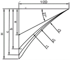
FIG. 1 is a schematic view of a female cone generatrix;
FIG. 2 is a schematic diagram of a four-pass progressive forming path of a concave tapered member with a generatrix in the shape of an arc of a circle;
FIG. 3 is a schematic view of a female taper progressive forming path having a generatrix radius R of 100, a height H of 50, and a base opening diameter D of 100;
fig. 4 is a thickness profile of a concave cone machined using the present invention.
Detailed Description
The invention will be further explained with reference to the drawings.
As shown in fig. 1-2, the concave conical sidewall generatrices may be of various types, such as hyperbolic, circular arc, etc. The circular arc is representative. The schematic diagram of the concave conical part is shown in FIG. 1, and the geometric parameters comprise a bus radius R, a height H, a bottom edge opening diameter D and an initial plate thickness t0Bottom fillet radius r. Four machining paths are arranged on a numerical control machine according to the model of the concave conical part by the numerical control machine according to the concave conical part, and are machined and formed gradually, wherein the four machining paths are shown in figure 2.
The concave conical part machining method comprises the following steps:
step 1: designing a basic path, processing a target concave conical piece, selecting a plurality of groups of concave conical pieces with the bus radius R, the height H and the bottom edge opening diameter D, and designing a four-pass progressive forming path as the basic path;
step 2: extracting key variables, wherein the key variables in the forming path of the concave conical piece are R, H, D, a, b, c, rl, R2 and R3;
in the first pass path, the inclination angle is a straight cone with an included angle of 27 degrees with the x axis. And rl is the radius of the circular arc of the second pass. r2 is the third pass arc radius, r3 is the fourth pass arc radius, which is also the final target bus radius.
The general formula of the forming path equation for each pass is as follows:
the first time: a straight cone Y1 with an included angle of 27 degrees with the x axis x tan27 degrees
And (3) a second pass: concave arc with radius r1
And a third step: concave arc with radius r2
And a fourth pass: concave arc R3 with radius R3 ═ R
Wherein H is the concave cone height and D is the concave cone bottom opening diameter. And Yl is a path equation of a straight line segment of the first forming path, the coordinates of the intersection point of the straight line segment and the y axis are (0, a), a is 1/2, D is tan alpha, and x is [0,1/2D ]. In the second-pass forming path, the coordinates of the intersection point of the concave arc having the radius r1 and the y-axis are (0, b), and b is 0.8 × H. In the second-pass forming path, the coordinates of the intersection point of the concave arc having the radius r2 and the y-axis are (0, c), and c is 0.92 × H. In the fourth-pass forming path, R represents the generatrix radius of the final target product, and the bottom of the fourth pass requires a fillet.
Wherein the R range satisfies During the machining process, the radius of the forming tool head is R/20, and the axial feeding amount is R/500.
When the method is adopted to process the concave conical part with the bus radius R of 100, the height H of 50 and the bottom edge opening diameter D of 100, the initial blank area S is selected0Is pi (D/2) ^2, and the area S of the deformed plateTheory of the invention,STheory of the inventionThe value can be obtained by calculating the area of the curved surface in a UG advanced simulation command, and the original thickness of the plate is t0Assuming that the wall thickness of the formed product is uniform and tTheory of the invention。
The method can be obtained according to the principle that the volume is not changed before and after deformation: sTheory of the invention*tTheory of the invention=S0*t0
The theoretical wall thickness t of the workpiece can be calculatedTheory of the inventionThe wall thickness of the general part is tTheory of the inventionThe wall thickness is approximately considered to be uniform within the range of (1 +/-10%) mm, and the wall thickness respectively corresponds to the upper limit and the lower limit of the theoretical wall thickness of a workpiece.
The original thickness of the selected plate is t02.0mm, processing a concave conical part with the R of 100mm, the H of 50mm and the bottom edge opening diameter D of 100mm, calling UG advanced simulation commands to calculate the curved surface area S, and calculating the curved surface area S according to the STheory of the invention*tTheory of the invention=S0*t0Formula to get tTheory of the inventionWhen the thickness of the wall is 1.405mm, the wall thickness of the product is approximately uniform within the range of 1.2645-1.5455 mm. The forming method comprises the following steps of processing a straight cone according to a straight cone path equation in a first step, forming the straight cone with an included angle of 27 degrees with an x-axis by using a straight cone Y1-x tan27 degrees,
wherein the ordinate a of the intersection with the y axis is 1/2D tan α is 25.5mm, the second pass processes the concave arc part with radius r1, the concave arc with radius r1, wherein the ordinate b of the intersection point of the Y axis is 0.8
H 40 mm;
the third secondary processing comprises the steps of processing a concave arc part with the radius of r2, processing a concave arc with the radius of r2, wherein the ordinate c of the intersection point of the Y axis is 0.92
H 46 mm; and (3) processing a concave arc part with the radius of R3 in a fourth pass, and obtaining a concave conical piece after the processing is finished, wherein the concave arc R3 with the radius of R3 is 100mm, the radius of the forming tool head is R/20, namely 5mm, and the axial feeding amount is R/500, namely 0.2mm during the processing.
The wall thickness distribution diagram of the concave conical piece obtained by processing on the numerical control machine tool by adopting the four-pass forming path is shown in fig. 4, and as can be seen from the thickness distribution curve in fig. 4, the wall thickness value of the finished piece is basically within the range of the upper limit and the lower limit of the theoretical wall thickness of 1.2645-1.5455 mm, the wall thickness is approximately considered to be uniform, and no significant thinning occurs. The forming method is used for processing the concave conical part, and the uniformity of the wall thickness of the part can be well improved.
The process of gradually forming and processing the concave-conical part on the numerical control machine tool can be roughly divided into blanking, machine tool preparation, fixture installation and adjustment, blank positioning and clamping, forming tool installation, processing code introduction, program compiling and debugging and machine tool processing. The preparation work before the experiment mainly comprises path design, three-dimensional solid modeling and machine tool machining code generation, which can be carried out in a CAM module of computer UG software, and the CAM module of the UG software automatically generates a forming path and a corresponding G code through the setting of processing parameters in the UG. During the molding pass, the UG software CAM module can be usedPassThe path equation of the numerical control machining program is rotated around a vertical shaft, and a three-dimensional modeling which can be performed at an earlier stage is generated, wherein the numerical control machining program cannot be immediately executed after being introduced into a machine tool, and the unification of the coordinate center of the machine tool and the default center in the program needs to be ensured. The specific operation steps are that firstly, the three coordinate axes are adjustedAnd when the tool is positioned at the base point, XYZ three-coordinate axis tool setting is carried out. The center of the forming tool is set in the direction X, Y so that it has a coordinate of 0 at the center of the outer contour support plate and the pressure plate. And setting the coordinate to be 0 when the lowest point of the tool head just contacts the plate material in the Z direction. After the XYZ three-coordinate axis tool setting is finished, a supporting base and a forming tool are installed, an upper pressing plate and a lower pressing plate with proper sizes are selected, plates are pressed, and the device is fixed through bolts. After the preparation of the previous stages is finished, program compiling execution can be carried out, and after the numerical control program is compiled and debugged without errors, the numerical control program can be started to carry out the gradual forming of the concave conical part.
Claims (6)
1. A method for gradually forming a concave conical part with a circular arc bus is characterized in that a four-time processing path is arranged on a numerical control machine tool according to a model of the concave conical part, and the method for gradually forming the concave conical part comprises the following steps:
(1) processing a straight cone according to a straight cone path equation in the first pass, wherein the path equation is as follows:
Y1=x*tan27°;
(2) the second pass is used for processing the concave arc part with the radius r1, and the path equation is as follows:

(3) the third time is to machine the concave arc part with the radius r2, and the path equation is as follows:

(4) and (3) processing the concave arc part with the radius of r3 in the fourth pass, and obtaining the concave conical part after the processing is finished, wherein the path equation is as follows:
r3=R;
h is the height of the concave cone, D is the opening diameter of the bottom edge of the concave cone, and R is the radius of a generatrix of the concave cone.
2. The method for progressively forming a concave tapered member having a generatrix in the shape of an arc according to claim 1, wherein in the step (1), the intersection coordinates of the path with the y-axis are (0, a), a-1/2 x D, and x is [0,1/2D ].
3. The method for progressively forming a concave tapered member having a circular arc-shaped generatrix according to claim 1, wherein the coordinates of the intersection point of the path with the y-axis in the step (2) are (0, b), and b is 0.8 × H.
4. The method for progressively forming a concave tapered member having a circular arc-shaped generatrix according to claim 1, wherein the coordinates of the intersection point of the path with the y-axis in the step (3) are (0, c), and c is 0.92 × H.
5. Method for the progressive forming of a female cone with a generatrix in the shape of a circular arc according to claim 1, characterized in that in said step (4)
6. The method for progressively forming a concave tapered part with a circular arc generatrix according to claim 1, wherein the radius of the forming tool head is R/20 and the axial feed is R/500 during the machining process.
Priority Applications (1)
| Application Number | Priority Date | Filing Date | Title |
|---|---|---|---|
| CN201711457866.5A CN108196508B (en) | 2017-12-27 | 2017-12-27 | Method for gradually forming concave conical part with arc-shaped bus |
Applications Claiming Priority (1)
| Application Number | Priority Date | Filing Date | Title |
|---|---|---|---|
| CN201711457866.5A CN108196508B (en) | 2017-12-27 | 2017-12-27 | Method for gradually forming concave conical part with arc-shaped bus |
Publications (2)
| Publication Number | Publication Date |
|---|---|
| CN108196508A CN108196508A (en) | 2018-06-22 |
| CN108196508B true CN108196508B (en) | 2020-09-11 |
Family
ID=62585603
Family Applications (1)
| Application Number | Title | Priority Date | Filing Date |
|---|---|---|---|
| CN201711457866.5A Active CN108196508B (en) | 2017-12-27 | 2017-12-27 | Method for gradually forming concave conical part with arc-shaped bus |
Country Status (1)
| Country | Link |
|---|---|
| CN (1) | CN108196508B (en) |
Families Citing this family (3)
| Publication number | Priority date | Publication date | Assignee | Title |
|---|---|---|---|---|
| CN113020421A (en) * | 2021-03-11 | 2021-06-25 | 东南大学 | Forming method of deep cylindrical part |
| CN113523059B (en) * | 2021-07-19 | 2023-10-13 | 东南大学 | Outer flange flanging forming method |
| CN114643311A (en) * | 2022-03-14 | 2022-06-21 | 东南大学 | Forming method of cylindrical part |
Citations (1)
| Publication number | Priority date | Publication date | Assignee | Title |
|---|---|---|---|---|
| CN105522020A (en) * | 2015-12-18 | 2016-04-27 | 东南大学 | Incremental forming method for hemispherical shell and auxiliary forming device for hemispherical shell |
-
2017
- 2017-12-27 CN CN201711457866.5A patent/CN108196508B/en active Active
Patent Citations (1)
| Publication number | Priority date | Publication date | Assignee | Title |
|---|---|---|---|---|
| CN105522020A (en) * | 2015-12-18 | 2016-04-27 | 东南大学 | Incremental forming method for hemispherical shell and auxiliary forming device for hemispherical shell |
Non-Patent Citations (2)
| Title |
|---|
| 75_锥形件渐进成形路径的参数化;贾耀高等;《塑性工程学报》;20150508;全文 * |
| 锥形件渐进成形路径的参数化研究;贾耀高;《中国优秀硕士学位论文全文数据库 工程科技Ⅱ辑》;20160815;第3-5章 * |
Also Published As
| Publication number | Publication date |
|---|---|
| CN108196508A (en) | 2018-06-22 |
Similar Documents
| Publication | Publication Date | Title |
|---|---|---|
| CN108196508B (en) | Method for gradually forming concave conical part with arc-shaped bus | |
| CN110802153B (en) | Deep drawing forming process for aluminum alloy deep paraboloid cylindrical part | |
| CN102172698B (en) | Composite gradual plate forming device and method | |
| CN105396944A (en) | Bridging stamping die | |
| CN104772634B (en) | Positioning clamping device for processing elastic check ring | |
| CN210413777U (en) | Tool for adjusting precision deviation of multi-axis numerical control machine tool | |
| Tisza et al. | Experimental and numerical study of a milling machine-based dieless incremental sheet forming | |
| CN103949909A (en) | CNC (computer numerical control) machined spherical piece combined clamp and clamping method | |
| CN104002166A (en) | Auxiliary tooling and process for machining thin wall annular part | |
| CN112705972A (en) | Device and method for automatic clamping and secondary positioning of production line products | |
| CN101920452B (en) | Production method for water chamber head of nuclear power equipment | |
| CN110369581B (en) | Forming method of convex curved platform piece | |
| CN110125242B (en) | Method for forming concave conical part with parabolic generatrix | |
| CN105643194B (en) | The lathe clamping producing process of electric motor end cap | |
| CN112338454B (en) | Three-dimensional simulation machining tool and method for special-shaped stainless steel thin-wall part | |
| CN201988933U (en) | Fixture for processing split-type round-inside and square-outside female die | |
| CN104607889B (en) | A kind of manufacture method of hyperboloid shaping mould frock | |
| CN210648040U (en) | Multi-station transfer die for automobile radiator water filling port | |
| CN108941318B (en) | Mirror image dieless machining method for metal sheet metal part | |
| CN114888169B (en) | Composite incremental forming method for sheet material | |
| CN205413998U (en) | Supplementary shaper that takes shape that advances gradually of hemisphere shell spare | |
| CN108907633A (en) | A kind of planetary cycloid reducer pin wheel housing internal tooth processing method | |
| CN101708584A (en) | Method for grinding workpiece slope for batch production | |
| KR100811299B1 (en) | Method and apparatus for manufacturing ball-stud | |
| CN114055229B (en) | Machining automatic production line and quick production changing method |
Legal Events
| Date | Code | Title | Description |
|---|---|---|---|
| PB01 | Publication | ||
| PB01 | Publication | ||
| SE01 | Entry into force of request for substantive examination | ||
| SE01 | Entry into force of request for substantive examination | ||
| GR01 | Patent grant | ||
| GR01 | Patent grant |