CN108140374B - Resonator, device with resonator and noise reduction system - Google Patents
Resonator, device with resonator and noise reduction system Download PDFInfo
- Publication number
- CN108140374B CN108140374B CN201680035122.1A CN201680035122A CN108140374B CN 108140374 B CN108140374 B CN 108140374B CN 201680035122 A CN201680035122 A CN 201680035122A CN 108140374 B CN108140374 B CN 108140374B
- Authority
- CN
- China
- Prior art keywords
- resonator
- resonators
- chain
- aperture
- base
- Prior art date
- Legal status (The legal status is an assumption and is not a legal conclusion. Google has not performed a legal analysis and makes no representation as to the accuracy of the status listed.)
- Active
Links
Images


Classifications
-
- G—PHYSICS
- G10—MUSICAL INSTRUMENTS; ACOUSTICS
- G10K—SOUND-PRODUCING DEVICES; METHODS OR DEVICES FOR PROTECTING AGAINST, OR FOR DAMPING, NOISE OR OTHER ACOUSTIC WAVES IN GENERAL; ACOUSTICS NOT OTHERWISE PROVIDED FOR
- G10K11/00—Methods or devices for transmitting, conducting or directing sound in general; Methods or devices for protecting against, or for damping, noise or other acoustic waves in general
- G10K11/16—Methods or devices for protecting against, or for damping, noise or other acoustic waves in general
- G10K11/172—Methods or devices for protecting against, or for damping, noise or other acoustic waves in general using resonance effects
-
- E—FIXED CONSTRUCTIONS
- E21—EARTH DRILLING; MINING
- E21B—EARTH DRILLING, e.g. DEEP DRILLING; OBTAINING OIL, GAS, WATER, SOLUBLE OR MELTABLE MATERIALS OR A SLURRY OF MINERALS FROM WELLS
- E21B41/00—Equipment or details not covered by groups E21B15/00 - E21B40/00
- E21B41/0007—Equipment or details not covered by groups E21B15/00 - E21B40/00 for underwater installations
-
- E—FIXED CONSTRUCTIONS
- E02—HYDRAULIC ENGINEERING; FOUNDATIONS; SOIL SHIFTING
- E02B—HYDRAULIC ENGINEERING
- E02B17/00—Artificial islands mounted on piles or like supports, e.g. platforms on raisable legs or offshore constructions; Construction methods therefor
- E02B17/0017—Means for protecting offshore constructions
-
- G—PHYSICS
- G10—MUSICAL INSTRUMENTS; ACOUSTICS
- G10K—SOUND-PRODUCING DEVICES; METHODS OR DEVICES FOR PROTECTING AGAINST, OR FOR DAMPING, NOISE OR OTHER ACOUSTIC WAVES IN GENERAL; ACOUSTICS NOT OTHERWISE PROVIDED FOR
- G10K2200/00—Details of methods or devices for transmitting, conducting or directing sound in general
- G10K2200/11—Underwater, e.g. transducers for generating acoustic waves underwater
Abstract
Acoustic resonators formed by injection molding or other processes that allow the shape, size, orientation and arrangement of each resonator to be customized. Tailoring the characteristics of the resonator allows its resonant frequency to be adjusted based on its intended deployment. The non-periodic or non-uniform arrangement of resonators may increase the level of noise reduction compared to a periodic or uniform arrangement of resonators. The chain slot includes a recess that receives a chain that supports a plurality of resonator rows or frames. In the stowed configuration, the chain slot pivots toward the row/frame to more compactly stow the panels of the resonators.
Description
RELATED APPLICATIONS
This application claims priority to U.S. provisional application No.62/181,374 entitled "injection molded noise abatement assembly and deployment system" filed on 18/6/2015, which is incorporated herein by reference.
Technical Field
The present disclosure relates to a reduced noise abatement device for underwater sound emissions, such as noise from marine vessels, oil and mineral drilling operations, and marine construction and demolition.
Background
Various underwater noise reduction devices have been proposed. Some are achieved by a form factor surrounding or deployed near the source of the underwater noise. U.S. patent application publication No. 2011/0031062, entitled "apparatus for suppressing and dispersing underwater sound in a liquid," describes a plurality of buoyant gas enclosures (air-containing balloons) attached to a rigid underwater frame that absorb underwater sound in a frequency range determined by the dimensions of the gas enclosures. U.S. patent application publication No. 2015/0170631, entitled "underwater noise reduction system and deployment apparatus using an open ended resonator assembly," discloses a system of submersible open ended gas resonators that can be deployed in an underwater noise environment to attenuate noise from underwater. These and related applications and documents are incorporated herein by reference.
Underwater noise reduction systems are intended to mitigate artificial noise in order to reduce its environmental impact. Pile driving for offshore construction, oil and gas drilling platforms and marine vessels are examples of noise that is undesirable and should be mitigated. However, installation, deployment, and packaging of subsea noise abatement systems can be challenging, as these devices are typically bulky and heavy to store and deploy.
Furthermore, current noise reduction systems rely on a combination of materials such as rubber, plastic, and/or metal. Constructing a system consisting of a non-homogenous system may be more expensive than a homogenous system processed in a single material.
The present application relates to underwater noise reduction devices and systems and methods of storing and deploying such devices.
Disclosure of Invention
The exemplary embodiments described herein have innovative features, none of which is essential or solely responsible for its desirable attributes. The following description and the annexed drawings set forth in detail certain illustrative implementations of the disclosure, which are indicative of several exemplary ways in which the various principles of the disclosure may be practiced. The illustrative examples, however, are not exhaustive of the many possible implementations of the disclosure. Some of the advantageous features will now be summarized without limiting the scope of the claims. Other objects, benefits and novel features of the present disclosure will be set forth in the following detailed description of the disclosure when considered in conjunction with the drawings, which are intended to illustrate and not to limit the invention.
In one aspect, the present invention is directed to a resonator for suppressing acoustic energy from a source in a liquid. The resonator includes a base having a first planar surface and a second planar surface, the first and second planar surfaces being parallel to each other. The resonator further includes a hollow body having, in a cross-section orthogonal to the second planar surface of the base, a first end, a second end, and a sidewall between the first end and the second end, the second end integrally connected to the second surface of the base, the body having an aperture defined in the first end, the aperture extending from the first end to the second end, the aperture defining a volume in the hollow body, the hollow body configured to retain a gas in the volume when the resonator is disposed in the liquid with the aperture aligned with a direction of gravitational force.
In another aspect, the present invention is directed to an apparatus for suppressing acoustic energy from a source in a liquid. The device includes a base having a first planar surface and a second planar surface, the first and second planar surfaces being parallel to each other. The apparatus also includes a plurality of hollow bodies, each hollow body having, in cross-section orthogonal to the second planar surface, a first end, a second end, and a sidewall between the first end and the second end, the second end integrally connected to the second surface of the base, the body having an aperture defined in the first end, the aperture extending from the first end to the second end, the aperture defining a volume in the hollow body, the hollow body configured to retain a gas in the volume when the resonator is disposed in the liquid with the aperture aligned with the direction of gravitational pull. The device also includes a plurality of holes defined in the base, the holes being disposed between at least some of the hollow bodies.
In another aspect, the present invention is directed to a noise abatement system. The system includes a plurality of collapsible frames. The system also includes a chain passing through an aperture defined in each collapsible frame, the chain mechanically connecting and supporting the collapsible frames. The system also includes a plurality of elongated chain slots (chain guard), each chain slot pivotably connected to the frame adjacent to the aperture, the chain slots having bodies defining recesses along a length of the chain slot to at least partially receive the chain, the chain slots configured to pivot from (a) an expanded position in which the length of the chain slot is orthogonal to the respective frame to (b) a closed position in which the length of the chain slot is parallel to the respective frame. The system also includes a plurality of resonators disposed on each of the frames, each resonator including a hollow body having an open end, a closed end, and a sidewall between the open end and the closed end, the closed end integrally connected to a first face of a base disposed on the respective frame.
Drawings
For a fuller understanding of the nature and advantages of the present invention, reference should be made to the following detailed description of the preferred embodiments taken in conjunction with the accompanying drawings in which:
fig. 1 illustrates an underwater noise reduction device according to an embodiment;
fig. 2 illustrates an example of a panel with respect to a resonator in a collapsed or stowed configuration, according to an embodiment;
FIG. 3 illustrates an embodiment of an acoustic resonator that may be disposed on the apparatus of FIG. 1;
fig. 4 illustrates a perspective view of rows of resonators in a panel according to an embodiment;
FIG. 5 illustrates an enlarged view of the chain and elongated support illustrated in FIG. 4;
FIG. 6 illustrates an enlarged view of the chain and chain groove in a partially collapsed or partially stowed state;
FIG. 7 is a perspective view of the chain and chain groove;
FIG. 8 is a top view of the chain slot illustrated in FIG. 7 with a representative resonator row arrangement;
FIG. 9 is a perspective view of a plurality of plates in a deployed configuration;
FIG. 10 is a perspective view of the panel in the stowed configuration;
FIG. 11 is a perspective view of an array of resonators in a periodic array;
FIG. 12 is a perspective view of an array of resonators in a random or aperiodic array;
fig. 13 is a top view of a resonator array according to an embodiment;
FIG. 14 is a view of the array illustrated in FIG. 13 from the opposite side of the base;
FIG. 15 illustrates a resonator having a generally balloon shape in cross-section;
FIG. 16 illustrates a resonator having a generally mushroom-shaped cross-section;
FIG. 17 illustrates a resonator having a wider cross-section at a first end thereof than the illustrated resonators illustrated in FIGS. 15 and 16;
FIG. 18 illustrates a resonator in which the cross-sectional width at a first end is greater than the cross-sectional width at a second end;
FIG. 19 illustrates a simplified characterization of a resonator;
FIG. 20 is an image illustrating a comparison of a mathematical model of resonance frequency against experimental data for the deployment depth of a resonator;
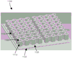
fig. 21 illustrates an example of a randomized resonator assembly and a periodic resonator assembly; and
fig. 22 is an image illustrating a comparison of the sound reduction of a random resonator assembly versus a periodic resonator assembly measured in a test.
Detailed Description
Fig. 1 illustrates a subsea noise reduction device 100 according to an embodiment. The noise reduction device 100 may be lowered into a body of water surrounding or adjacent to a noise generating event or thing, such as a drilling platform, vessel, or other machine. The plurality of resonators 125 disposed on the vertically disposed plates of the noise reduction device 100 resonate to absorb acoustic energy and thereby reduce radiated acoustic energy originating from the site of the noise-generating event or thing. In some embodiments the resonator 125 includes a chamber that retains a gas, such as air, nitrogen, argon, or a combination thereof. For example, the resonator 125 may be of the type disclosed in U.S. serial No.14/494,700 entitled "underwater noise abatement panel and resonator structure", filed on 24.9.2014, U.S. serial No.14/494,700, which is incorporated herein by reference. In some embodiments, the resonators 125 are arranged in a two-dimensional or three-dimensional array. The resonators 125 may be arranged in rows 110, and each row may be connected to an adjacent row(s) by a plurality of cords 120.
The apparatus 100 may be towed behind a noisy marine vessel. Several such devices may be assembled into a system for reducing underwater noise emissions from a vessel. Systems like this may also be assembled around one or more working faces of mining or drilling equipment.
The noise reduction apparatus 100 may be extendable and deployable, for example as described in U.S. serial No.14/590,177 entitled "underwater noise abatement apparatus and deployment system" filed 1/6/2015, which is incorporated herein by reference. One or more cords connecting each row of resonator plates may be raised or lowered, which may cause the plates to retract vertically, similar to a venetian blind. An embodiment of the panel 200 in the retracted or stowed configuration is illustrated in fig. 2.
Fig. 3 illustrates an embodiment of an acoustic resonator 325 that may be disposed on device 100. Resonator 325 is employed in a two-fluid environment, where a first fluid is represented by "a" and a second fluid is represented by "B" in the figures. For illustrative purposes only, the two-fluid environment may be a liquid-gas environment. In a more particular illustrative embodiment, the liquid 330 may be water and the gas may be air. In a more particular embodiment, the liquid may be seawater (or other natural body of water) and the gas may be atmospheric air. For example, the first fluid "a" may be seawater and the second fluid "B" may be air.
Embodiments of resonator 325 have an outer body or shell 310, the outer body or shell 310 having a main volume 315 of fluid B contained therein. The body 310 may be substantially spherical, cylindrical, or bulbous. A tapered section 312 near one end lowers the wall of the body 310 to a narrowed neck section 314. Neck section 314 has a mouth 316 that provides an opening that allows fluid a and fluid B to be in fluid communication with each other at a fluid interface 320 in or near neck section 314. In operation, pressure oscillations (acoustic noise) present in fluid a outside resonator 325 will be sensed in or near neck section 314 of the resonator. As illustrated by dashed line 322, expansion, contraction, pressure changes, and other hydrodynamic variables may cause the fluid interface to move back and forth within the region of neck 314.
The resonator of fig. 3 is thus configured to allow a reduction in acoustic energy in the vicinity of resonator 325 by helmholtz resonator oscillation, depending on several factors, such as the composition of fluid a and fluid B and the volume of the second fluid B with respect to the volume of fluid B and/or fluid a in neck section 314, the cross-sectional area of opening 216, and other factors.
Fig. 4 illustrates a perspective view of multiple rows 410 of resonators 425 in a panel 400, according to an embodiment. Each row 410 is connected to an adjacent row by a first chain 430 and a second chain 440. The chains 430, 440 are each mechanically connected to a chain trough (chain guide)450, and the chain trough 450 may be contracted and/or pivoted from a vertical or orthogonal position with respect to the plane of the row 410 to a horizontal or parallel position with respect to the row. The chain slots 450 connected to the row 410' are in a partially deployed (or retracted) configuration. The chain channel 450 may be an elongated support made of rigid plastic or metal (e.g., corrosion resistant metal).
Fig. 5 illustrates an enlarged view 500 of the chain and elongated support described above. As illustrated, the chains 530, 540 are mechanically coupled to respective slots 550. Each slot 550 has a planar surface 560, the planar surface 560 having two side walls 562, 564 extending from the planar surface 560 towards the respective chain 530, 540. Sidewalls 562, 564 also extend toward adjacent edge 515 of row 510 when slot 550 is in a vertical orientation with respect to row 510. The sidewalls define a recess 570 that receives the chains 330, 340. The recess 570 may have a depth greater than or equal to the width of the chain, such that the width of the chain is sufficiently disposed in the recess 570.
Row recesses or openings 57 are defined in row 510 to receive slots 550 when slots 550 are in the horizontal/stowed position (i.e., when the length of slots 550 is parallel to the plane defined by row 510). The row recesses/openings 575 may extend partially or fully through the depth of the (e.g., holes) row 510. In some embodiments, the recesses/openings 575 extend across the width of the rows. In some embodiments, the recess/opening 575 substantially conforms to the shape of the slot 550. The recess/opening 575 may have a depth sufficient to substantially receive the trough 550 in a horizontal or stowed position.
FIG. 6 illustrates an enlarged view 600 of the chain 630 and chain slot 650 in a partially collapsed or partially stowed state. The chain slot 650 is provided on the chain slot arrangement 660. Device 660 includes structure to which slot 650 is attached, such as at pivot point 670 that pivotally connects device 660 to the end of slot 650. The device 660 may have a height 665 that is greater than or equal to the depth of the slot 650 such that a recess 680 in the device 660 may substantially receive the slot 650 in its horizontal or stowed position. As discussed above, the device 660 may be disposed on a row of resonator plates, for example in apertures or holes defined in the row to receive the device 660.
Fig. 7 is a perspective view 700 of the chain 630 and slot 650 described above. As illustrated, the slot 650 has been pivoted downward to a horizontal or stowed position. In the horizontal position, the slot 650 is disposed in a recess 680 of the device 660. As discussed above, if the device 660 is sufficiently disposed in a recess in a row of resonator plates, the slot 650 lies in a plane defined by the row. The recess 680 receiving the slot 650 allows for a more compact configuration in the collapsed/stowed state, such as when the slot 350 is deployed in a panel having multiple rows.
In some embodiments, the chain 630 is disposed on an interior or unexposed surface of the trough 650 (e.g., on a surface of the trough 650 that faces the recess 680 when the trough 650 is in a horizontal position). In some embodiments, one strand is disposed on an exposed surface of the trough 650, while the other strand is disposed on an interior/unexposed surface of the trough 650.
Fig. 8 is a top view 800 of chain slots 650 arranged in a representative row 810 of resonators 820. Chain 630 is disposed on an exposed surface of slot 650 in a retracted or stowed configuration.
Fig. 9 is a perspective view of a plurality of plates 900 in a deployed configuration. Each plate 900 includes a row (two or more) having chains and chain slots as described above.
Fig. 10 is a perspective view of the plate 1000 in the stowed configuration. As illustrated, the plate 1000 can be stowed very compactly due to the pivotable/rotatable slots as described above.
Fig. 11 is a perspective view of an array 1100 of resonators 1110. The resonator 1110 is disposed on a flat base 1120. The resonator 1110 is generally cylindrical in shape and extends from the base 1120. A hole 1130 is defined at the distal end of the resonator 1110 from the base 1120. Array 1100 includes a plurality of rows 1115 and columns 1125 or resonators 1110. However, resonators 1110 may be arranged in other configurations, such as in irregularly-spaced and/or irregularly-aligned rows 1115 and columns 1125 as described above.
In operation, the resonator array 1100 is disposed in the ocean (or other body of water) with the apertures 1130 of the resonators 1110 facing in the direction of gravitational force (i.e., toward the bottom of the ocean). Such disposition causes air to be trapped between the hole 1130 and the base 1120 to form a resonant body.
The resonator 1110 may be produced by injection molding, for example, using a thermoplastic material. Similar production processes (e.g., liquid injection molding, reaction injection molding, etc.) are contemplated and included in the present disclosure. The resonator 1110 may be integrally connected to the base 1120 in an injection molding process. The resonator 1110 and the base 1120 can be formed from the same material, such as a thermoplastic material as discussed above. By producing the resonator 1110 using injection molding (or similar/equivalent processes), the shape, alignment, orientation, spacing, dimensions, etc. of the resonator 1110 can be varied as desired.
For example, array 1100 may include resonators 1110 having different sizes and/or shapes to enhance acoustic suppression of the resonator array. For example, some resonators may have a generally circular cross-section while others may have a generally rectangular cross-section. Additionally or alternatively, some resonators may have a first aperture size (e.g., narrow aperture) and other resonators may have a second void size (e.g., wide aperture). Additionally, or alternatively, some resonators may have a first body with a first height and/or a first wall thickness, while other resonators may have a second body with a second height and/or a second wall thickness. Such sizes and/or shapes may be distributed regularly or irregularly throughout the array. Additionally or alternatively, the spacing between adjacent resonators may be regular or irregular. Additionally or alternatively, the alignment of resonators in a given row and/or the alignment of resonators in a column 1125 may be regular or irregular, such an array 1200 being illustrated in fig. 12.
Fig. 13 is a top view of an array 1300 of resonators 1310 according to an embodiment. As illustrated, resonators 1310 are irregularly spaced or offset, and thus each resonator 1310 is not sufficiently aligned in a row 1315 or column 1325. Conversely, the spacing of at least some of resonators 1310 is positively or negatively biased such that some resonators 1310 are spaced closer together relative to one another while other resonators 1310 are spaced further apart from one another. A plurality of holes 1340 are defined in the base 1320 of the array 1300. Holes 1340 are disposed between adjacent resonators 1310 and are arranged in columns and rows parallel to columns 1325 and rows 1315 (there is no negative/positive bias discussed above). The holes 1340 may facilitate the submersion of the array 1300 into a liquid, such as a body of water (e.g., a lake or the ocean), by allowing air bubbles to pass through the holes 1625. As the liquid displaces the air bubbles, the array 1300 becomes less buoyant and more easily submerged into the ocean.
In some embodiments, the holes 1340 are disposed only between some adjacent resonators 1310. The holes 1340 between adjacent resonators 1310 may be offset, wherein the holes 1340 are closer to a first resonator 1310 than a second resonator 1310. Additionally, or alternatively, the holes 1340 may be arranged in a regular or irregular pattern. Additionally, or alternatively, the apertures 1340 may have different sizes and/or shapes. As discussed above, the array 1300 is deployed in a liquid (e.g., an ocean or other body of water) with the apertures 1330 facing in the direction of gravitational force (e.g., toward the bottom of the ocean).
Fig. 14 is a view of the array 1300 from the opposite side of the base 1320. Since resonators 1310 are on opposite sides of base 1320, only holes 1340 are visible from this figure. In operation, the exposed surface shown in fig. 14 will face the ocean surface, while the opposite side (from which the resonator 1310 extends) will face the sea floor. As discussed above, a second set of holes 1350 is defined in the base 1320 to receive respective strings that are disposed between each array to form a plate of resonators. The tether may be tied to a vessel or structure to raise or lower the plate.
Fig. 15-18 illustrate cross-sections of alternative shapes of resonators according to example embodiments. For example, fig. 15 illustrates a resonator 1500 having a generally balloon shape in cross-section, the resonator 1500 having a narrow cross-sectional width at a first end 1510 and a large cross-sectional width at a second end 1520. The first end 1510 includes an aperture 1530 that faces the seabed in the deployed orientation. As such, water may enter the aperture and fill portions of resonator 1500 to waterline 1540, which waterline 1540 may be a function of the cross-sectional width of aperture 1530, the cross-sectional width of first end 1510, the cross-sectional width of second end 1520, and the deployment depth of resonator 1500. As the resonator 1500 is deployed deeper into the ocean, the water pressure on the exterior surface of the resonator 1500 may increase. The increased water pressure may cause more water to enter the resonator 1500 and, thus, cause the waterline 1540 to be positioned higher in the resonator 1500 (i.e., toward the second end 1520 of the resonator 1500).
As the resonator 1500 fills with water, the effective mass of the resonator 1500 increases. Thus, by varying one or more of the size of the aperture 1530, the dimensions (i.e., cross-sectional width) of the resonator 1500 (e.g., the cross-sectional ratio at the first end 1510 and the second end 1520), and the deployment depth of the resonator 1500 in the ocean, the effective mass of the resonator 1500 can be tailored. By adjusting the effective mass, the resonant frequency of the resonator 1500 can be "tuned" to more effectively attenuate a given undersea noise. Furthermore, the higher effective mass of the resonator 1500 may have enhanced acoustic suppression performance due to the correspondingly higher inertia of the resonator 1500.
Fig. 16 illustrates a resonator 1600 having a generally mushroom-shaped cross-section and a representative waterline 1640. Fig. 17 illustrates a resonator 1700 having a wider cross-section at first end 1710 than in fig. 16 or 17. In addition, the cross-sectional width of first end 1710 is greater than the cross-sectional width of second end 1720, and the cross-sectional width of intermediate portion 1730 is greater than the cross-sectional widths of first end 1710 and second end 1720. A representative water line 1740 is also illustrated in fig. 17. Fig. 18 illustrates a resonator 1800 in which the cross-sectional width at the first end 1810 is greater than the cross-sectional width at the second end 1820. Generally, the resonator 1800 has a shape similar to a cone. The wider cross-sectional width at first end 1810 (and correspondingly wider aperture 1830) may cause waterline 1840 to be lower compared to resonators 1500, 1600, or 1700. Note that the cross-sectional shapes illustrated in fig. 15-18 are provided as examples, and this disclosure contemplates any and all cross-sectional arrangements and shapes of resonators. Further, on a second cross-section orthogonal to the cross-sectional plane illustrated in fig. 15-18, the resonator illustrated in fig. 15-18 may be generally circular or elliptical, rectangular, symmetrical, or asymmetrical.
Fig. 19 illustrates a simplified characterization of a resonator 1900. The resonator 1900 includes a hollow cavity 1925 and a neck portion 1950 having an aperture 1975. The hollow cavity 1925 is configured to retain a volume of air VairWhile the resonator 1900 is deployed in a liquid (e.g., water) and the neck portion 1950 is oriented toward the direction of gravitational pull (e.g., toward the bottom of the ocean). When resonator 1900 is in a deployed state, the neck portion is at least partially filled with a liquid. Thus, resonator 1900 may be used as a two-fluid helmholtz resonator.
The acoustic behavior of the resonator is determined by the volume of gas (V)air) Length (L) of liquid-filled neck portion 1950neck) And the surface area of the aperture 1975 (SA _ aper). Volume of gas (V)air) And length (L) of liquid-filled neck portion 1950neck) Depending on the pressure (e.g., water pressure) exerted by the liquid on the resonator 1900, the pressure is a function of the deployment depth of the resonator 1900. The depth dependence of these parameters may be such that the resonant frequency and acoustic suppression of the resonator 1900 are also depth dependent. As will be appreciated by those skilled in the art, the resonant frequency, deployment depth, Vair、LneckAnd SA _ aper can be mathematically modeled.
A comparison of a mathematical model of resonance frequency versus experimental data versus deployment depth is illustrated in fig. 20. As illustrated on the right hand side of the figure, the comparison is repeated for a first resonator size 2025 and a second resonator size 2050. Experimental data were obtained using resonators made of different materials (steel, aluminum and PVC) in tanks (data points with "x") and fresh water lakes (data points with circles).
Fig. 21 illustrates an example of a randomized resonator assembly 2100A and a periodic resonator assembly 2100B comprising a resonator as described herein. The assembly was manufactured on an automated router using 2 inch by 16 inch blocks of Ultra High Molecular Weight Polyethylene (UHMWPE). The internal gauge of each individual resonator is 0.875 inches in diameter and 1.75 inches in height, which corresponds to a resonant frequency near 100Hz when deployed within the first few meters of liquid. As described below, the location of the resonator in random array 2100A is generated by perturbing the periodic array location with a pseudo-random number generator.
For ease of production and assembly, the array of individual resonator cavities is designed as a single unitary component. The component may be described as a flat plate having a discrete number of hollow, cylindrical protrusions that are open to the atmosphere on the end opposite the plate. Each protrusion forms a single resonator. The placement of the resonators on the face of the panel may be determined by a pseudo-random perturbation of the lattice. The unit length in the square may be set to be twice the inner diameter of the resonator. A pseudo-random number generator may be used to determine the two-dimensional (i.e., in the x-y plane perpendicular to the bumps) perturbation of each node in the grid. The magnitude of the perturbation may be limited so that the outer diameters of adjacent resonators do not become touching. With these factors, the central axis of each resonator can be defined as a specific perturbation node.
As described above, the spatial structure of the resonator may have an effect on sound propagating through or radiated by the array. Depending on the structure, sound propagation or radiation may be enhanced or suppressed by the array. Randomization of the location of the resonators in the array may help to ensure that the phases of the dispersed and re-radiated sound waves passing through the array are incoherent such that the net spread of sound is minimized. In the experiment, the randomized resonator assembly 2100A achieved about 6dB more sound reduction around the resonant frequency of the individual resonators, which was about 85Hz at test water depths, than the periodic resonator array 2100B. A comparison of the random versus periodic resonator assembly sound reduction measured in the test is illustrated in fig. 22.
Upon reading this disclosure, those skilled in the art will appreciate that the concepts presented herein may be generalized or specialized to a given application at hand. As such, the present disclosure is not intended to be limited to the described exemplary embodiments, which are presented for purposes of illustration. Many other similar and equivalent embodiments and extensions to these concepts may be included herein.
Claims (27)
1. A resonator for suppressing acoustic energy from a source in a liquid, the resonator comprising:
a base having a first planar surface and a second planar surface, the first and second planar surfaces being parallel to each other;
a hollow body having, in a cross-section orthogonal to the second planar surface of the base, a first end, a second end, and a sidewall between the first end and the second end, the second end integrally connected to the second planar surface of the base, the hollow body extending away from the first planar surface and the second planar surface of the base, the body having an aperture defined in the first end, the aperture extending from the first end to the second end, the aperture defining a volume in the hollow body, the hollow body configured to retain a gas in the volume when the resonator is disposed in the liquid with the aperture aligned with a direction of gravitational pull; and
at least one aperture defined in the base, the at least one aperture being laterally offset from the hollow body.
2. The resonator of claim 1, wherein said hollow body has a first portion disposed adjacent to said first end and a second portion disposed adjacent to said second end, wherein said first portion is narrower than said second portion.
3. The resonator of claim 1, wherein said base and said hollow body are injection molded.
4. The resonator of claim 3, wherein said base and said hollow body are formed of the same material.
5. The resonator of claim 3, wherein said hollow body is in the shape of a balloon.
6. The resonator of claim 3, wherein said hollow body is mushroom shaped.
7. The resonator of claim 2, wherein a ratio of widths of said first portion and said second portion is selected based on a depth of deployment of said resonator in said liquid.
8. The resonator of claim 7, wherein said ratio is selected such that a desired amount of said liquid enters said volume at said depth.
9. The resonator of claim 8, wherein said resonator has a resonant frequency based at least in part on a desired amount of said liquid.
10. A device for suppressing acoustic energy from a source in a liquid, the device comprising:
a base having a first planar surface and a second planar surface, the first and second planar surfaces being parallel to each other;
a plurality of hollow bodies forming a resonator, each hollow body having, in a cross-section orthogonal to the second planar surface, a first end, a second end, and a side wall between the first end and the second end, the second end integrally connected to the second planar surface of the base, the hollow bodies having an aperture defined in the first end, the aperture extending from the first end to the second end, the aperture defining a volume in the hollow bodies, the hollow bodies configured to retain a gas in the volume when the apparatus is disposed in the liquid with the aperture aligned with a direction of gravitational pull; and
a plurality of holes defined in the base, the holes being disposed between at least some of the hollow bodies.
11. The device of claim 10, wherein the holes are configured to allow gas bubbles to pass through to reduce buoyancy of the device when the device is submerged in the liquid.
12. The apparatus of claim 10, wherein the resonators are arranged in an array having a plurality of columns and rows.
13. The apparatus of claim 12, wherein at least some of said resonators are biased in either said columns or said rows.
14. The apparatus of claim 12, wherein said resonators comprise a first resonator having a first shape and a second resonator having a second shape, said first shape being different from said second shape.
15. The apparatus of claim 14, wherein said first and second resonators are randomly distributed in said array.
16. The apparatus of claim 12, wherein said resonators comprise a first resonator having a first height and a second resonator having a second height.
17. The apparatus of claim 12, wherein a distance between adjacent resonators throughout the array is variable.
18. The apparatus of claim 17, wherein the distances across the array are randomly distributed.
19. A noise abatement system, the noise abatement system comprising:
a plurality of collapsible frames;
a chain passing through an aperture defined in each collapsible frame, the chain mechanically connecting and supporting the collapsible frames;
a plurality of elongate chain slots, each chain slot pivotably connected to a respective frame adjacent to the aperture, the chain slots having bodies defining recesses along a length of the chain slot to at least partially receive the chain, the chain slots configured to pivot from (a) an open position in which the length of the chain slot is orthogonal to the respective frame to (b) a closed position in which the length of the chain slot is parallel to the respective frame; and
a plurality of resonators disposed on each of the frames, each resonator including a hollow body having an open end, a closed end, and a sidewall between the open end and the closed end, the closed end integrally connected to a first surface of a base disposed on the respective frame.
20. The system of claim 19, wherein the body has an aperture defined in the open end and extending from the open end to the closed end, the aperture defining a volume in the hollow body configured to retain gas in the volume when the resonator is submerged in a liquid with the aperture aligned with a direction of gravitational force.
21. The system of claim 19, wherein the body has a first portion disposed adjacent the open end and a second portion disposed adjacent the closed end, wherein the first portion is narrower than the second portion.
22. The system of claim 19, wherein the resonators are irregularly spaced on at least one frame.
23. The system of claim 19, wherein said resonators have a plurality of shapes and/or sizes.
24. The system of claim 23, wherein the plurality of shapes and/or sizes are randomly distributed on at least one frame.
25. The system of claim 19, wherein the system is configured to collapse from a deployed configuration such that the frames are in an extended position such that the frames are spaced farther apart than when they are stowed to a stowed configuration such that the frames are in a collapsed position such that the resonators are spaced closer together than when they are deployed.
26. The system of claim 25, wherein the chain trough is in the deployed position when the system is in the deployed configuration and the chain trough is in the closed position when the system is in the stowed configuration.
27. The system of claim 19, wherein a plurality of holes are defined in the base, the holes being disposed between at least some of the resonators.
Applications Claiming Priority (3)
| Application Number | Priority Date | Filing Date | Title |
|---|---|---|---|
| US201562181374P | 2015-06-18 | 2015-06-18 | |
| US62/181,374 | 2015-06-18 | ||
| PCT/US2016/038096 WO2016205661A1 (en) | 2015-06-18 | 2016-06-17 | Injection molded noise abatement assembly and deployment system |
Publications (2)
| Publication Number | Publication Date |
|---|---|
| CN108140374A CN108140374A (en) | 2018-06-08 |
| CN108140374B true CN108140374B (en) | 2022-03-29 |
Family
ID=57546374
Family Applications (1)
| Application Number | Title | Priority Date | Filing Date |
|---|---|---|---|
| CN201680035122.1A Active CN108140374B (en) | 2015-06-18 | 2016-06-17 | Resonator, device with resonator and noise reduction system |
Country Status (9)
| Country | Link |
|---|---|
| US (1) | US9812112B2 (en) |
| EP (1) | EP3311378A4 (en) |
| JP (1) | JP6720223B2 (en) |
| CN (1) | CN108140374B (en) |
| AU (1) | AU2016280283B2 (en) |
| CA (1) | CA2987124C (en) |
| HK (1) | HK1252170A1 (en) |
| TW (1) | TWI625446B (en) |
| WO (1) | WO2016205661A1 (en) |
Families Citing this family (3)
| Publication number | Priority date | Publication date | Assignee | Title |
|---|---|---|---|---|
| EP4094251A4 (en) * | 2020-01-21 | 2024-02-21 | Adbm Corp | Simultaneously attenuating high-frequencies and amplifying low-frequencies of underwater sounds |
| CN111739498B (en) * | 2020-06-01 | 2023-10-24 | 南京航空航天大学 | Cross slotting low-frequency underwater sound absorption deep sub-wavelength super structure |
| US20230184047A1 (en) * | 2021-12-09 | 2023-06-15 | Chevron U.S.A. Inc. | Noise mitigation of subsea oil and gas equipment using subsea acoustic insulation |
Citations (4)
| Publication number | Priority date | Publication date | Assignee | Title |
|---|---|---|---|---|
| US5587564A (en) * | 1994-04-27 | 1996-12-24 | Firma Carl Freudenberg | Noise damper |
| JPH09228506A (en) * | 1996-02-27 | 1997-09-02 | Osaka Yakin Kogyo Kk | Sound absorbing material |
| CN1491308A (en) * | 2000-12-21 | 2004-04-21 | ����ɪ-���¹�˾ | Double layer acoustic liner and fluid pressurizing device and method utilizing same |
| CN104364840A (en) * | 2012-06-26 | 2015-02-18 | 赫克赛尔公司 | Structure with active acoustic openings |
Family Cites Families (29)
| Publication number | Priority date | Publication date | Assignee | Title |
|---|---|---|---|---|
| US3022632A (en) * | 1955-10-31 | 1962-02-27 | Jersey Prod Res Co | Breakwater |
| US3487645A (en) * | 1968-08-21 | 1970-01-06 | Litton Systems Inc | Wave damping device |
| JPS535819A (en) * | 1976-07-06 | 1978-01-19 | Shibaura Eng Works Ltd | Sound insulation screen device |
| JPH0261699A (en) * | 1988-08-27 | 1990-03-01 | Mitsui Eng & Shipbuild Co Ltd | Multi-cell sound absorption plate |
| JP3072438B2 (en) * | 1991-07-17 | 2000-07-31 | 沖電気工業株式会社 | Highly water-resistant sound-insulating material and method for producing the same |
| JPH0592441A (en) * | 1991-10-02 | 1993-04-16 | Sumitomo Rubber Ind Ltd | Sound-insulating panel |
| US5457291A (en) * | 1992-02-13 | 1995-10-10 | Richardson; Brian E. | Sound-attenuating panel |
| JPH08239949A (en) * | 1995-03-02 | 1996-09-17 | Sankyo Alum Ind Co Ltd | Screen-surface forming material |
| JP3654988B2 (en) * | 1996-01-10 | 2005-06-02 | 株式会社フジタ | Variable sound insulation wall |
| JP3421982B2 (en) * | 1997-12-16 | 2003-06-30 | 早川ゴム株式会社 | Soundproof floor material and soundproof floor structure |
| US20030006090A1 (en) * | 2001-06-27 | 2003-01-09 | Reed John Douglas | Broadband noise-suppressing barrier |
| EP1483457A1 (en) * | 2002-03-14 | 2004-12-08 | Wienerberger Bricks N.V. | Acoustic construction element |
| JP4716916B2 (en) * | 2005-04-21 | 2011-07-06 | 日産自動車株式会社 | Silencer |
| FR2885919B1 (en) * | 2005-05-20 | 2008-10-24 | Saipem S A Sa | SOFT DEVICE DAMPER FOR MOVING WATER |
| DE102008017418B4 (en) | 2008-04-03 | 2010-08-19 | Gottfried Wilhelm Leibniz Universität Hannover | Device for reducing the transmission and propagation of sound and / or wave motions in a liquid |
| US20100243369A1 (en) * | 2009-03-31 | 2010-09-30 | Nuform Building Technologies Inc. | Highway noise barrier |
| US8662249B2 (en) * | 2009-09-25 | 2014-03-04 | Schlumberger Technology Corporation | Multi-layered sound attenuation mechanism |
| WO2011077377A2 (en) * | 2009-12-21 | 2011-06-30 | Moshe Seri | Submersible swimming pool deck |
| JP5672801B2 (en) * | 2010-07-02 | 2015-02-18 | 横浜ゴム株式会社 | Underwater sound insulation |
| FR2968861B1 (en) * | 2010-12-10 | 2013-09-27 | Commissariat Energie Atomique | METHOD FOR MANUFACTURING ACOUSTIC WAVE RESONATOR COMPRISING A SUSPENDED MEMBRANE |
| JP5626995B2 (en) * | 2011-02-15 | 2014-11-19 | 株式会社神戸製鋼所 | Sound absorption panel |
| US8689935B2 (en) | 2011-04-22 | 2014-04-08 | Board Of Regents Of The University Of Texas System | Abating low-frequency noise using encapsulated gas bubbles |
| US8387746B2 (en) * | 2011-05-27 | 2013-03-05 | John Parkin | Systems and methods for the reduction of underwater acoustical noise |
| CA2868436C (en) * | 2012-03-26 | 2017-03-14 | Karl-Heinz Elmer | Method for handling a hydro sound damper and device for reducing underwater sound |
| US8651233B2 (en) * | 2012-05-08 | 2014-02-18 | Hexcel Corporation | Acoustic structure with increased bandwidth suppression |
| KR101807783B1 (en) * | 2012-06-18 | 2018-01-18 | 목포해양대학교 산학협력단 | Soundproof duct for ship propellors using resonators |
| CN106164390B (en) * | 2013-09-24 | 2018-08-24 | 普雷斯顿·威尔逊 | Underwater noise cuts down plate and resonator structure |
| WO2015095192A2 (en) * | 2013-12-17 | 2015-06-25 | Adbm Corp. | Underwater noise reduction system using open-ended resonator assembly and deployment apparatus |
| US9488026B2 (en) * | 2014-01-06 | 2016-11-08 | Board Of Regents, The University Of Texas System | Underwater noise abatement apparatus and deployment system |
-
2016
- 2016-06-16 TW TW105118895A patent/TWI625446B/en active
- 2016-06-17 CN CN201680035122.1A patent/CN108140374B/en active Active
- 2016-06-17 US US15/185,856 patent/US9812112B2/en active Active
- 2016-06-17 CA CA2987124A patent/CA2987124C/en active Active
- 2016-06-17 WO PCT/US2016/038096 patent/WO2016205661A1/en active Application Filing
- 2016-06-17 JP JP2017565769A patent/JP6720223B2/en active Active
- 2016-06-17 AU AU2016280283A patent/AU2016280283B2/en active Active
- 2016-06-17 EP EP16812531.8A patent/EP3311378A4/en active Pending
-
2018
- 2018-09-07 HK HK18111563.4A patent/HK1252170A1/en unknown
Patent Citations (4)
| Publication number | Priority date | Publication date | Assignee | Title |
|---|---|---|---|---|
| US5587564A (en) * | 1994-04-27 | 1996-12-24 | Firma Carl Freudenberg | Noise damper |
| JPH09228506A (en) * | 1996-02-27 | 1997-09-02 | Osaka Yakin Kogyo Kk | Sound absorbing material |
| CN1491308A (en) * | 2000-12-21 | 2004-04-21 | ����ɪ-���¹�˾ | Double layer acoustic liner and fluid pressurizing device and method utilizing same |
| CN104364840A (en) * | 2012-06-26 | 2015-02-18 | 赫克赛尔公司 | Structure with active acoustic openings |
Also Published As
| Publication number | Publication date |
|---|---|
| TWI625446B (en) | 2018-06-01 |
| CN108140374A (en) | 2018-06-08 |
| JP2018519544A (en) | 2018-07-19 |
| AU2016280283A1 (en) | 2017-12-07 |
| EP3311378A4 (en) | 2019-01-23 |
| NZ737558A (en) | 2021-09-24 |
| HK1252170A1 (en) | 2019-05-17 |
| US20160372101A1 (en) | 2016-12-22 |
| WO2016205661A1 (en) | 2016-12-22 |
| TW201716663A (en) | 2017-05-16 |
| JP6720223B2 (en) | 2020-07-08 |
| CA2987124A1 (en) | 2016-12-22 |
| US9812112B2 (en) | 2017-11-07 |
| EP3311378A1 (en) | 2018-04-25 |
| CA2987124C (en) | 2020-05-26 |
| AU2016280283B2 (en) | 2021-02-25 |
Similar Documents
| Publication | Publication Date | Title |
|---|---|---|
| CN108140374B (en) | Resonator, device with resonator and noise reduction system | |
| CN106164390B (en) | Underwater noise cuts down plate and resonator structure | |
| CN110029965B (en) | Underwater noise reduction system and deployment device using open-ended resonator assembly | |
| AU2009231037A1 (en) | Device for damping and scattering hydrosound in a liquid | |
| JPH0417830B2 (en) | ||
| Wilson et al. | Injection molded noise abatement assembly and deployment system | |
| NZ737558B2 (en) | Injection molded noise abatement assembly and deployment system | |
| TWI764833B (en) | Underwater noise mitigation module | |
| JP7100317B2 (en) | Overpass suppression device | |
| EP2955278B1 (en) | Noise suppression apparatus | |
| Abdellah | EVALUATION OF WAVE ATTENUATION BY FLEXIBLE CONTAINER BREAKWATER |
Legal Events
| Date | Code | Title | Description |
|---|---|---|---|
| PB01 | Publication | ||
| PB01 | Publication | ||
| SE01 | Entry into force of request for substantive examination | ||
| SE01 | Entry into force of request for substantive examination | ||
| GR01 | Patent grant | ||
| GR01 | Patent grant |