CN108098611B - Clamp flat tongs - Google Patents
Clamp flat tongs Download PDFInfo
- Publication number
- CN108098611B CN108098611B CN201711432060.0A CN201711432060A CN108098611B CN 108098611 B CN108098611 B CN 108098611B CN 201711432060 A CN201711432060 A CN 201711432060A CN 108098611 B CN108098611 B CN 108098611B
- Authority
- CN
- China
- Prior art keywords
- groove
- positioning
- screw
- pliers
- sliding
- Prior art date
- Legal status (The legal status is an assumption and is not a legal conclusion. Google has not performed a legal analysis and makes no representation as to the accuracy of the status listed.)
- Active
Links
Images


Classifications
-
- B—PERFORMING OPERATIONS; TRANSPORTING
- B25—HAND TOOLS; PORTABLE POWER-DRIVEN TOOLS; MANIPULATORS
- B25B—TOOLS OR BENCH DEVICES NOT OTHERWISE PROVIDED FOR, FOR FASTENING, CONNECTING, DISENGAGING OR HOLDING
- B25B1/00—Vices
- B25B1/06—Arrangements for positively actuating jaws
Abstract
The invention discloses a pair of flat tongs, which comprises a tong body, a positioning block and a small tong, wherein the positioning block and the small tong are both positioned at the top of the tong body, the small tong is positioned at one side of the positioning block, one side of the tong body is provided with a positioning plate, the positioning plate is movably arranged on the tong body through a third screw, and a positioning screw is movably arranged on the positioning plate; the clamp comprises a clamp body and is characterized in that sawtooth-shaped grooves are formed in the top side of the clamp body, the bottom side of a positioning block and the bottom side of a small clamp, a T-shaped groove is formed in the top of the clamp body, a first T-shaped key is movably mounted in the T-shaped groove, fine grooves with the same specification are formed in the bottom of the positioning block and the bottom of the small clamp, the top of the first T-shaped key extends into the fine grooves, a first screw is movably mounted on the positioning block, and the first screw is matched with the first T-shaped key. The invention can be used for the production of various parts, greatly improves the production efficiency, improves the product processing quality and meets the use requirements of people.
Description
Technical Field
The invention relates to the field of flat tongs, in particular to a pair of tongs flat tongs.
Background
At present, a plurality of patents refer to a plurality of mechanism schemes of a quick vice, but the function direction of the mechanism schemes is that the mechanism schemes aim at changing parts to adapt to workpieces with larger size range change, so that time wasted by frequently changing the parts is not only required to pay more labor for operators, but also production efficiency is greatly influenced.
Disclosure of Invention
The invention aims to solve one of the defects in the prior art and provides a pair of flat tongs.
In order to achieve the purpose, the invention adopts the following technical scheme:
a pair of flat tongs comprises a tong body, a positioning block and a small tong, wherein the positioning block and the small tong are both positioned at the top of the tong body, the small tong is positioned at one side of the positioning block, one side of the tong body is provided with a positioning plate, the positioning plate is movably arranged on the tong body through a third screw, and a positioning screw is movably arranged on the positioning plate;
the clamp comprises a clamp body, a positioning block, a small clamp and a pair of T-shaped keys, wherein the top side of the clamp body, the bottom side of the positioning block and the bottom side of the small clamp are respectively provided with a sawtooth-shaped groove, the top of the clamp body is provided with a T-shaped groove, the T-shaped groove is internally and movably provided with a first T-shaped key, the bottoms of the positioning block and the small clamp are respectively provided with a fine groove with the same specification, the top of the first T-shaped key extends into the fine groove, the positioning block is movably provided with a first screw, and;
the small clamp comprises a base body, a jacking jaw, a sliding wedge block, a compression screw, a second T-shaped key, a first spring, a side limiting nail, a baffle plate, an O-shaped ring tension spring, a pin shaft, a second screw and a second spring, wherein the side limiting nail is arranged on one side of the base body; the four pin shafts are respectively positioned on the front end surface and the rear end surface of the base body and the jacking jaw on two sides of the sliding wedge block, and the two pin shafts positioned on the front end surface and the two pin shafts positioned on the rear end surface of the base body and the jacking jaw are respectively connected through O-shaped ring tension springs; the lower end of the baffle is fixed at the lower end of the base body through a second screw, and the upper end of the baffle extends out of the protection arc-shaped plate towards the direction of the O-shaped ring tension spring;
the bottom of the clamp body is provided with a mounting seat, the top of the mounting seat is provided with a mounting groove, the bottom of the clamp body is fixedly welded with a mounting block, the mounting block is movably mounted in the mounting groove, a placing groove is formed on the inner wall of one side of the mounting groove, a clamping groove is formed on the inner wall of one side of the mounting block close to the placing groove, the notch of the clamping groove is arranged corresponding to the notch of the placing groove, a positioning sleeve is slidably mounted in the placing groove, one end of the positioning sleeve close to the clamping groove is movably clamped in the clamping groove, the two sides of the positioning sleeve are fixedly welded with limit blocks, the limit blocks are positioned in the placing groove, one side of the limit blocks, far away from the positioning sleeve, is slidably connected with the inner wall of the placing groove along the horizontal direction, a mounting hole is formed on the inner wall of one side of, the one end of axis of rotation extends to in the standing groove, the other end of axis of rotation extends to the outside of mount pad and fixed welding has the knob, and the knob be equipped with anti-skidding line on the surface, the hob is installed to the standing groove internal rotation, and the hob is close to the one end rotation cover of positioning sleeve and establish in the positioning sleeve, the hob is kept away from the one end of positioning sleeve and is kept away from the one end fixed connection of knob with the axis of rotation.
Preferably, one side of the jacking jaw close to the sliding wedge block is obliquely arranged, and the jacking jaw is in sliding connection with the sliding wedge block.
Preferably, the side limit pins are matched with the sliding wedge blocks.
Preferably, the first and second liquid crystal materials are,
preferably, the number of the second screws is four, and the baffle is matched with the second screws.
Preferably, the positioning plate is rotatably connected with the clamp body through a third screw.
Preferably, the positioning plate is provided with a through hole, and the positioning screw is movably arranged in the through hole.
Preferably, the screw rod is provided with an external thread, the inner wall of the positioning sleeve is provided with an internal thread, and the external thread on the screw rod is matched with the internal thread on the inner wall of the positioning sleeve.
Preferably, one side of the limiting block, which is far away from the positioning sleeve, is fixedly welded with a sliding block, the inner wall of the placing groove is provided with a sliding groove matched with the sliding block, and the sliding block is connected with the sliding groove in a sliding manner along the horizontal direction.
Preferably, the installation piece is equipped with two, and two installation piece symmetries set up, and the installation piece is the rectangle structure, and the mounting groove is the rectangular channel, and the installation piece contacts with the inner wall of mounting groove.
Compared with the prior art, the invention has the beneficial effects that:
in the invention, in the process of clamping the workpiece, the space inclined plane on the jacking jaw receives downward force, and the workpiece also receives downward pressure, so that the phenomenon of pressing and arching can not occur; because the screw is loosened and tightened only once during the model changing, the production efficiency is greatly improved, and the labor intensity is improved, so the invention has the advantages of safety, reliability, simple installation and convenient operation.
The clamp can be used for producing various parts, the production efficiency is greatly improved, the product processing quality is improved, the clamp body is convenient for people to install on the installation seat for people to use, the structure is simple, the installation and the operation are convenient, and the use requirements of people are met.
Drawings
FIG. 1 is a schematic three-dimensional structure of a pair of pliers of the present invention;
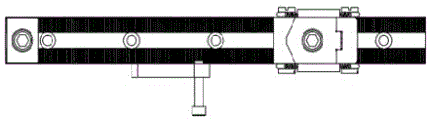
FIG. 2 is a side view of a clamp flat-nose pliers according to the present invention;
FIG. 3 is a cross-sectional view of the small clamp in section A of FIG. 2;
FIG. 4 is a schematic perspective view of a small pliers of a pliers flat-nose pliers according to the present invention;
FIG. 5 is a structural plan view of a pair of pliers of the present invention;
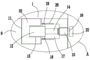
FIG. 6 is a schematic structural diagram of a clamp body and a mounting seat of the flat-nose pliers of the invention;
FIG. 7 is an enlarged view of portion A of FIG. 6 according to the present invention;
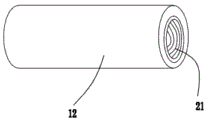
fig. 8 is a schematic perspective view of a positioning sleeve in a pair of pliers flat-nose pliers according to the present invention.
In the figure: the clamp comprises a clamp body 1, a positioning block 2, a first T-shaped key 3, a positioning plate 4, a first screw 5, a small clamp 6, a positioning screw 7, a third screw 8, a base body 6-1, a tight jaw 6-2, a sliding wedge 6-3, a compression screw 6-4, a second T-shaped key 6-5, a first spring 6-6, a side limiting nail 6-7, a baffle 6-8, an O-shaped ring tension spring 6-9, a pin shaft 6-10, a second screw 6-11, a second spring 6-12, a mounting seat 9, a mounting block 10, a mounting groove 11, a positioning sleeve 12, a clamping groove 13, a screw rod 14, a bearing 15, a rotating shaft 16, a placing groove 17, a limiting block 18, a sliding block 19, a sliding groove 20, an internal thread 21 and a knob 22.
Detailed Description
The technical solutions in the embodiments of the present invention will be clearly and completely described below with reference to the drawings in the embodiments of the present invention, and it is obvious that the described embodiments are only a part of the embodiments of the present invention, and not all of the embodiments.
Referring to fig. 1-8, a pair of flat tongs comprises a tongs body 1, a positioning block 2 and a small tongs 6, wherein the positioning block 2 and the small tongs 6 are both positioned at the top of the tongs body 1, the small tongs 6 is positioned at one side of the positioning block 2, one side of the tongs body 1 is provided with a positioning plate 4, the positioning plate 4 is movably arranged on the tongs body 1 through a third screw 8, and a positioning screw 7 is movably arranged on the positioning plate 4;
the top side of the clamp body 1, the bottom sides of the positioning block 2 and the small clamp 6 are respectively provided with a sawtooth-shaped groove, the top of the clamp body 1 is provided with a T-shaped groove, a first T-shaped key 3 is movably mounted in the T-shaped groove, the bottoms of the positioning block 2 and the small clamp 6 are respectively provided with a fine groove with the same specification, the top of the first T-shaped key 3 extends into the fine groove, a first screw 5 is movably mounted on the positioning block 2, and the first screw 5 is matched with the first T-shaped key 3;
the small clamp 6 comprises a base body 6-1, a jacking jaw 6-2, a sliding wedge 6-3, a compression screw 6-4, a second T-shaped key 6-5, a first spring 6-6, a side limiting nail 6-7, a baffle 6-8, an O-shaped ring tension spring 6-9, a pin shaft 6-10, a second screw 6-11 and a second spring 6-12, wherein the side limiting nail 6-7 is arranged on one side of the base body 6-1, the compression screw 6-4 is movably arranged on the second T-shaped key 6-5, the first spring 6-6 and the second spring 6-12 are both sleeved on the compression screw 6-4, the first spring 6-6 is positioned above the second spring 6-12, the sliding wedge 6-3 is positioned above the second T-shaped key 6-5, the jacking jaw 6-2 is positioned on one side of the sliding wedge 6-3 far away from the base body 6-1;
the bottom of the pliers body 1 is provided with a mounting seat 9, the top of the mounting seat 9 is provided with a mounting groove 11, the bottom of the pliers body 1 is fixedly welded with a mounting block 10, the mounting block 10 is movably mounted in the mounting groove 11, one side inner wall of the mounting groove 11 is provided with a placing groove 17, one side inner wall of the mounting block 10 close to the placing groove 17 is provided with a clamping groove 13, a notch of the clamping groove 13 is arranged corresponding to a notch of the placing groove 17, a positioning sleeve 12 is slidably mounted in the placing groove 17, one end of the positioning sleeve 12 close to the clamping groove 13 is movably clamped in the clamping groove 13, both sides of the positioning sleeve 12 are fixedly welded with limiting blocks 18, the limiting blocks 18 are positioned in the placing groove 17, one side of the limiting blocks 18 far away from the positioning sleeve 12 is connected with the inner wall of the placing groove 17 in a sliding manner along the horizontal direction, one side inner wall of the, a rotating shaft 16 is rotatably mounted on the bearing 15, one end of the rotating shaft 16 extends into the placing groove 17, the other end of the rotating shaft 16 extends to the outside of the mounting seat 9 and is fixedly welded with a knob 22, anti-skid lines are arranged on the surface of the knob 22, a spiral rod 14 is rotatably mounted in the placing groove 17, one end, close to the positioning sleeve 12, of the spiral rod 14 is rotatably sleeved in the positioning sleeve 12, and one end, far away from the positioning sleeve 12, of the spiral rod 14 is fixedly connected with one end, far away from the knob 22, of the rotating shaft 16;
the novel multifunctional wrench is characterized in that an external thread is arranged on the screw rod 14, an internal thread 21 is arranged on the inner wall of the positioning sleeve 12, the external thread on the screw rod 14 is matched with the internal thread 21 on the inner wall of the positioning sleeve 12, a sliding block 19 is fixedly welded on one side, far away from the positioning sleeve 12, of the limiting block 18, a sliding groove 20 matched with the sliding block 19 is formed in the inner wall of the placing groove 17, the sliding block 19 is in sliding connection with the sliding groove 20 along the horizontal direction, two mounting blocks 10 are arranged, the two mounting blocks 10 are symmetrically arranged, the mounting blocks 10 are of a rectangular structure, the mounting groove 11 is a rectangular groove, and the mounting blocks 10 are in contact with the inner wall of the mounting groove 11.
One side of the jacking jaw 6-2 close to the sliding wedge 6-3 is obliquely arranged, the jacking jaw 6-2 is in sliding connection with the sliding wedge 6-3, and the side limiting nail 6-7 is matched with the sliding wedge 6-3. Four pin shafts 6-10 are arranged, are respectively positioned on the front end surface and the rear end surface of the base body 6-1 and the jacking jaw 6-2 at two sides of the sliding wedge block 6-3, and are respectively connected between the two pin shafts 6-10 on the front end surface and the two pin shafts 6-10 on the rear end surface of the base body 6-1 and the jacking jaw 6-2 through O-shaped ring tension springs 6-9. The lower end of the baffle 6-8 is fixed at the lower end of the base body 6-1 through a second screw 6-11, and the upper end of the baffle extends out of the protection arc-shaped plate towards the direction of the O-shaped ring tension spring 6-9. Optionally, four second screws 6-11 are provided, and the baffle 6-8 is matched with the second screws 6-11. The positioning plate 4 is rotatably connected with the clamp body 1 through the third screw 8, the positioning plate 4 is provided with a through hole, and the positioning screw 7 is movably arranged in the through hole.
In the invention, when in use, the positioning block 2 completes the positioning in the width direction through the first T-shaped key 3, completes the positioning in the length direction through the tooth profile and is fixed on the clamp body 1 through the first screw 5; the rotary positioning plate 4 is fastened on the side surface of the clamp body 1 through a third screw 8 and rotates according to the structure of a workpiece, so that the workpiece can be positioned without interfering the processing of the workpiece, and then the length of the positioning screw 7 screwed into the positioning plate 4 is adjusted according to the length of the workpiece; the small clamp 6 completes width direction positioning through a second T-shaped key 6-5, completes length direction positioning through tooth shape, and is fixed on the clamp body 1 through a compression screw 6-4; the small clamp 6 is mainly divided into a base body 6-1, a jacking jaw 6-2, a sliding wedge 6-3, a compression screw 6-4 and the like. When the mold is changed, the compression screws 6-4 are loosened, the tooth shapes are meshed and separated, the small clamp 6 is integrally moved to a proper position, the small clamp 6 is put down, the clamp body 1 is meshed with the tooth shape of the base body 6-1, the compression screws 6-4 are pre-tightened, a workpiece is put down, the side face of the workpiece is tightly attached to the positioning screw 7, the compression screws 6-4 are continuously tightened, the sliding wedge blocks 6-3 are driven to slide downwards, the sliding wedge blocks 6-3 slide downwards, the jacking clamp jaws 6-2 matched with the sliding wedge blocks are driven to bear downward oblique thrust, so that the sliding wedge blocks horizontally slide outwards until the workpiece is contacted, the compression screws 6-4 are continuously tightened until the tooth shape meshing and the jacking blocks 6-2 jack the workpiece are completed in two steps, and the compression screws 6-4 are tightened in place; processing a workpiece, after the processing is finished, unscrewing a compression screw 6-4, lifting a sliding wedge block 6-3 upwards under the double actions of an O-shaped ring tension spring 6-9 (pulling a jacking jaw 6-2 inwards) and a second spring 6-12 (lifting the sliding wedge block 6-3 upwards), returning the jacking jaw 6-2, separating the jacking jaw from the workpiece, and unloading the workpiece; and repeating the operation to process the next workpiece.
Meanwhile, in the invention, the pliers body 1 is convenient for people to install on the installation seat 9 for the use of people, and the specific installation operation is as follows: earlier put into mounting groove 11 installation piece 10 of pincers body 1 bottom, then rotatory knob 22, knob 22 drives axis of rotation 16 and rotates on bearing 15, axis of rotation 16 drives hob 14 again and rotates, in hob 14 pivoted, the external screw thread that passes through on hob 14 again cooperates with internal thread 21 on the 12 inner walls of position sleeve, make position sleeve 12 horizontal migration on hob 14, position sleeve 12 removes to draw-in groove 13 from standing groove 17, after position sleeve 12 moves into draw-in groove 13 and clamps in groove 13, the installation is accomplished promptly, it is fixed like this through position sleeve 12 location installation, pincers body 1 is more firm also installed on mount pad 9, make things convenient for people to use.
The above description is only for the preferred embodiment of the present invention, but the scope of the present invention is not limited thereto, and any person skilled in the art should be considered to be within the technical scope of the present invention, and the technical solutions and the inventive concepts thereof according to the present invention should be equivalent or changed within the scope of the present invention.
Claims (9)
1. A pair of flat-nose pliers comprises a pliers body (1), a positioning block (2) and a small pliers (6), and is characterized in that the positioning block (2) and the small pliers (6) are both positioned at the top of the pliers body (1), the small pliers (6) are positioned on one side of the positioning block (2), a positioning plate (4) is arranged on one side of the pliers body (1), the positioning plate (4) is movably mounted on the pliers body (1) through a third screw (8), and a positioning screw (7) is movably mounted on the positioning plate (4);
the clamp comprises a clamp body (1), a positioning block (2) and a small clamp (6), wherein the top side of the clamp body (1), the bottom side of the positioning block (2) and the small clamp (6) are respectively provided with a sawtooth-shaped groove, the top of the clamp body (1) is provided with a T-shaped groove, a first T-shaped key (3) is movably arranged in the T-shaped groove, the bottoms of the positioning block (2) and the small clamp (6) are respectively provided with a fine groove with the same specification, the top of the first T-shaped key (3) extends into the fine groove, a first screw (5) is movably arranged on the positioning block (2), and the first screw (5) is matched with the first T-;
the small clamp (6) comprises a base body (6-1), a jacking jaw (6-2), a sliding wedge block (6-3), a compression screw (6-4), a second T-shaped key (6-5), a first spring (6-6), a side limiting nail (6-7), a baffle plate (6-8), an O-shaped ring tension spring (6-9), a pin shaft (6-10), a second screw (6-11) and a second spring (6-12), wherein the side limiting nail (6-7) is arranged on one side of the base body (6-1), the compression screw (6-4) is movably arranged on the second T-shaped key (6-5), the first spring (6-6) and the second spring (6-12) are both sleeved on the compression screw (6-4), and the first spring (6-6) is positioned above the second spring (6-12), the sliding wedge block (6-3) is positioned above the second T-shaped key (6-5), and the jacking jaw (6-2) is positioned on one side of the sliding wedge block (6-3) far away from the base body (6-1); the four pin shafts (6-10) are respectively positioned on the front end surface and the rear end surface of the base body (6-1) and the jacking jaw (6-2) at two sides of the sliding wedge block (6-3), and are respectively connected between the two pin shafts (6-10) at the front end surface and between the two pin shafts (6-10) at the rear end surface of the base body (6-1) and the jacking jaw (6-2) through O-shaped ring tension springs (6-9); the lower end of the baffle (6-8) is fixed at the lower end of the base body (6-1) through a second screw (6-11), and the upper end of the baffle extends out of the protection arc-shaped plate towards the direction of the O-shaped ring tension spring (6-9);
the bottom of the pincers body (1) is equipped with mount pad (9), mounting groove (11) have been seted up at the top of mount pad (9), the bottom fixed weld of the pincers body (1) has installation piece (10), and installation piece (10) movable mounting in mounting groove (11), standing groove (17) have been seted up on one side inner wall of mounting groove (11), draw-in groove (13) have been seted up on the one side inner wall that installation piece (10) are close to standing groove (17), and the notch of draw-in groove (13) sets up with the notch of standing groove (17) is corresponding, slidable mounting has location sleeve (12) in standing groove (17), and the one end activity that location sleeve (12) are close to draw-in groove (13) clamps in draw-in groove (13), the equal fixed weld in both sides of location sleeve (12) has stopper (18), and stopper (18) are located standing groove (17), stopper (18) keep away from one side of location sleeve (12) and the inner wall of standing groove (17) along the horizontal direction Sliding connection, the mounting hole has been seted up on one side inner wall that draw-in groove (13) was kept away from in standing groove (17), and fixed cover has connect bearing (15) in the mounting hole, and rotates on bearing (15) and install axis of rotation (16), the one end of axis of rotation (16) extends to in standing groove (17), the outside and the fixed welding that the other end of axis of rotation (16) extended to mount pad (9) have knob (22), and knob (22) be equipped with anti-skidding line on the surface, hob (14) are installed to standing groove (17) internal rotation, and hob (14) are close to the one end rotation cover of positioning sleeve (12) and are established in positioning sleeve (12), the one end fixed connection that knob (22) were kept away from with axis of rotation (16) to the one end that positioning sleeve (12) were kept away from in hob (14).
2. The flat-nose pliers according to claim 1, characterized in that the side of the top-clamping jaw (6-2) close to the sliding wedge (6-3) is inclined, and the top-clamping jaw (6-2) is connected with the sliding wedge (6-3) in a sliding way.
3. The pliers, according to claim 1, characterized in that the lateral limit pins (6-7) are adapted to the sliding wedges (6-3).
4. The pliers, according to claim 1, characterized in that the second screws (6-11) are provided in four and the stop plates (6-8) are adapted to the second screws (6-11).
5. The pliers, according to claim 1, characterized in that the positioning plate (4) is connected in rotation to the pliers body (1) by means of a third screw (8).
6. The flat-nose pliers as claimed in claim 1, wherein the positioning plate (4) is provided with a through hole, and the positioning screw (7) is movably mounted in the through hole.
7. The pliers according to claim 1, wherein the screw rod (14) is provided with an external thread, the inner wall of the positioning sleeve (12) is provided with an internal thread (21), and the external thread on the screw rod (14) is matched with the internal thread (21) on the inner wall of the positioning sleeve (12).
8. The flat-nose pliers as claimed in claim 1, wherein a sliding block (19) is fixedly welded on one side of the limiting block (18) far away from the positioning sleeve (12), a sliding groove (20) matched with the sliding block (19) is formed in the inner wall of the placing groove (17), and the sliding block (19) and the sliding groove (20) are connected in a sliding manner along the horizontal direction.
9. The flat-nose pliers according to claim 1, wherein there are two mounting blocks (10), and the two mounting blocks (10) are symmetrically arranged, the mounting blocks (10) have a rectangular structure, the mounting groove (11) is a rectangular groove, and the mounting blocks (10) are in contact with the inner wall of the mounting groove (11).
Priority Applications (1)
| Application Number | Priority Date | Filing Date | Title |
|---|---|---|---|
| CN201711432060.0A CN108098611B (en) | 2017-12-26 | 2017-12-26 | Clamp flat tongs |
Applications Claiming Priority (1)
| Application Number | Priority Date | Filing Date | Title |
|---|---|---|---|
| CN201711432060.0A CN108098611B (en) | 2017-12-26 | 2017-12-26 | Clamp flat tongs |
Publications (2)
| Publication Number | Publication Date |
|---|---|
| CN108098611A CN108098611A (en) | 2018-06-01 |
| CN108098611B true CN108098611B (en) | 2020-08-11 |
Family
ID=62213110
Family Applications (1)
| Application Number | Title | Priority Date | Filing Date |
|---|---|---|---|
| CN201711432060.0A Active CN108098611B (en) | 2017-12-26 | 2017-12-26 | Clamp flat tongs |
Country Status (1)
| Country | Link |
|---|---|
| CN (1) | CN108098611B (en) |
Families Citing this family (2)
| Publication number | Priority date | Publication date | Assignee | Title |
|---|---|---|---|---|
| CN109940426A (en) * | 2019-04-28 | 2019-06-28 | 株洲齿轮有限责任公司 | Mill symmetric double key groove clamp and slotting attachment |
| CN112692611A (en) * | 2020-12-31 | 2021-04-23 | 保定向阳航空精密机械有限公司 | Quick adjustment formula flat-nose pliers |
Citations (3)
| Publication number | Priority date | Publication date | Assignee | Title |
|---|---|---|---|---|
| US6343783B1 (en) * | 2000-03-14 | 2002-02-05 | Harrison Ke | Workbench |
| CN106181800A (en) * | 2016-08-04 | 2016-12-07 | 江门银特银数控机床有限公司 | A kind of coordinated type twoport vice |
| CN206084815U (en) * | 2016-10-13 | 2017-04-12 | 佰鑫源精密机械(厦门)有限公司 | But jack catch quick replacement vice and duplex position vice |
-
2017
- 2017-12-26 CN CN201711432060.0A patent/CN108098611B/en active Active
Patent Citations (3)
| Publication number | Priority date | Publication date | Assignee | Title |
|---|---|---|---|---|
| US6343783B1 (en) * | 2000-03-14 | 2002-02-05 | Harrison Ke | Workbench |
| CN106181800A (en) * | 2016-08-04 | 2016-12-07 | 江门银特银数控机床有限公司 | A kind of coordinated type twoport vice |
| CN206084815U (en) * | 2016-10-13 | 2017-04-12 | 佰鑫源精密机械(厦门)有限公司 | But jack catch quick replacement vice and duplex position vice |
Also Published As
| Publication number | Publication date |
|---|---|
| CN108098611A (en) | 2018-06-01 |
Similar Documents
| Publication | Publication Date | Title |
|---|---|---|
| CN105149984B (en) | A kind of grip device | |
| CN102990433B (en) | The auxiliary locator of machine vice | |
| CN106002404B (en) | A kind of clamping device of square workpiece | |
| CN108098611B (en) | Clamp flat tongs | |
| CN212887662U (en) | Robot clamping tool with adjustable width | |
| CN211163662U (en) | Casting part machining clamp easy to clamp | |
| CN209811808U (en) | Auxiliary holding clamp for cutting building pipe | |
| CN209902105U (en) | Bending machine clamping device convenient to it is rotatory | |
| CN104128733A (en) | Adjustable welding set | |
| CN107639433A (en) | Workpiece floating clamping device | |
| CN211275989U (en) | Bending mechanism of bending machine | |
| CN210010727U (en) | Pipe clamping device convenient for adjusting diameter of clamping opening | |
| CN107716718B (en) | Flexible die for stretch bending of section bar | |
| CN111070088A (en) | Turnover workbench for polishing of die | |
| CN108515103A (en) | Forge piece stamping equipment | |
| CN210731747U (en) | Flat hydraulic clamp | |
| CN211588418U (en) | Forge press jaw frame device | |
| CN112743361A (en) | Fixing device for metal processing | |
| CN203062281U (en) | Sliding clamping device | |
| CN112317631A (en) | Workpiece clamping mechanism of punching machine | |
| CN210023542U (en) | Stamping workpiece diaphragm upset anchor clamps | |
| CN216065012U (en) | Equipment based on shaping and processing of aluminum product form | |
| CN217225142U (en) | Hydraulic vice bench | |
| CN214519659U (en) | Bench clamp | |
| CN210335677U (en) | Jig for machining automobile parts |
Legal Events
| Date | Code | Title | Description |
|---|---|---|---|
| PB01 | Publication | ||
| PB01 | Publication | ||
| SE01 | Entry into force of request for substantive examination | ||
| SE01 | Entry into force of request for substantive examination | ||
| GR01 | Patent grant | ||
| GR01 | Patent grant |