CN108027112B - Lighting device - Google Patents
Lighting device Download PDFInfo
- Publication number
- CN108027112B CN108027112B CN201680056070.6A CN201680056070A CN108027112B CN 108027112 B CN108027112 B CN 108027112B CN 201680056070 A CN201680056070 A CN 201680056070A CN 108027112 B CN108027112 B CN 108027112B
- Authority
- CN
- China
- Prior art keywords
- light
- light emitting
- sheet
- heat sink
- recess
- Prior art date
- Legal status (The legal status is an assumption and is not a legal conclusion. Google has not performed a legal analysis and makes no representation as to the accuracy of the status listed.)
- Active
Links
Images


Classifications
-
- F—MECHANICAL ENGINEERING; LIGHTING; HEATING; WEAPONS; BLASTING
- F21—LIGHTING
- F21V—FUNCTIONAL FEATURES OR DETAILS OF LIGHTING DEVICES OR SYSTEMS THEREOF; STRUCTURAL COMBINATIONS OF LIGHTING DEVICES WITH OTHER ARTICLES, NOT OTHERWISE PROVIDED FOR
- F21V7/00—Reflectors for light sources
- F21V7/04—Optical design
-
- F—MECHANICAL ENGINEERING; LIGHTING; HEATING; WEAPONS; BLASTING
- F21—LIGHTING
- F21K—NON-ELECTRIC LIGHT SOURCES USING LUMINESCENCE; LIGHT SOURCES USING ELECTROCHEMILUMINESCENCE; LIGHT SOURCES USING CHARGES OF COMBUSTIBLE MATERIAL; LIGHT SOURCES USING SEMICONDUCTOR DEVICES AS LIGHT-GENERATING ELEMENTS; LIGHT SOURCES NOT OTHERWISE PROVIDED FOR
- F21K9/00—Light sources using semiconductor devices as light-generating elements, e.g. using light-emitting diodes [LED] or lasers
- F21K9/60—Optical arrangements integrated in the light source, e.g. for improving the colour rendering index or the light extraction
- F21K9/62—Optical arrangements integrated in the light source, e.g. for improving the colour rendering index or the light extraction using mixing chambers, e.g. housings with reflective walls
-
- F—MECHANICAL ENGINEERING; LIGHTING; HEATING; WEAPONS; BLASTING
- F21—LIGHTING
- F21K—NON-ELECTRIC LIGHT SOURCES USING LUMINESCENCE; LIGHT SOURCES USING ELECTROCHEMILUMINESCENCE; LIGHT SOURCES USING CHARGES OF COMBUSTIBLE MATERIAL; LIGHT SOURCES USING SEMICONDUCTOR DEVICES AS LIGHT-GENERATING ELEMENTS; LIGHT SOURCES NOT OTHERWISE PROVIDED FOR
- F21K9/00—Light sources using semiconductor devices as light-generating elements, e.g. using light-emitting diodes [LED] or lasers
- F21K9/60—Optical arrangements integrated in the light source, e.g. for improving the colour rendering index or the light extraction
- F21K9/65—Optical arrangements integrated in the light source, e.g. for improving the colour rendering index or the light extraction specially adapted for changing the characteristics or the distribution of the light, e.g. by adjustment of parts
-
- F—MECHANICAL ENGINEERING; LIGHTING; HEATING; WEAPONS; BLASTING
- F21—LIGHTING
- F21K—NON-ELECTRIC LIGHT SOURCES USING LUMINESCENCE; LIGHT SOURCES USING ELECTROCHEMILUMINESCENCE; LIGHT SOURCES USING CHARGES OF COMBUSTIBLE MATERIAL; LIGHT SOURCES USING SEMICONDUCTOR DEVICES AS LIGHT-GENERATING ELEMENTS; LIGHT SOURCES NOT OTHERWISE PROVIDED FOR
- F21K9/00—Light sources using semiconductor devices as light-generating elements, e.g. using light-emitting diodes [LED] or lasers
- F21K9/60—Optical arrangements integrated in the light source, e.g. for improving the colour rendering index or the light extraction
- F21K9/66—Details of globes or covers forming part of the light source
-
- F—MECHANICAL ENGINEERING; LIGHTING; HEATING; WEAPONS; BLASTING
- F21—LIGHTING
- F21S—NON-PORTABLE LIGHTING DEVICES; SYSTEMS THEREOF; VEHICLE LIGHTING DEVICES SPECIALLY ADAPTED FOR VEHICLE EXTERIORS
- F21S2/00—Systems of lighting devices, not provided for in main groups F21S4/00 - F21S10/00 or F21S19/00, e.g. of modular construction
-
- F—MECHANICAL ENGINEERING; LIGHTING; HEATING; WEAPONS; BLASTING
- F21—LIGHTING
- F21S—NON-PORTABLE LIGHTING DEVICES; SYSTEMS THEREOF; VEHICLE LIGHTING DEVICES SPECIALLY ADAPTED FOR VEHICLE EXTERIORS
- F21S8/00—Lighting devices intended for fixed installation
- F21S8/02—Lighting devices intended for fixed installation of recess-mounted type, e.g. downlighters
- F21S8/026—Lighting devices intended for fixed installation of recess-mounted type, e.g. downlighters intended to be recessed in a ceiling or like overhead structure, e.g. suspended ceiling
-
- F—MECHANICAL ENGINEERING; LIGHTING; HEATING; WEAPONS; BLASTING
- F21—LIGHTING
- F21V—FUNCTIONAL FEATURES OR DETAILS OF LIGHTING DEVICES OR SYSTEMS THEREOF; STRUCTURAL COMBINATIONS OF LIGHTING DEVICES WITH OTHER ARTICLES, NOT OTHERWISE PROVIDED FOR
- F21V15/00—Protecting lighting devices from damage
- F21V15/01—Housings, e.g. material or assembling of housing parts
- F21V15/013—Housings, e.g. material or assembling of housing parts the housing being an extrusion
-
- F—MECHANICAL ENGINEERING; LIGHTING; HEATING; WEAPONS; BLASTING
- F21—LIGHTING
- F21V—FUNCTIONAL FEATURES OR DETAILS OF LIGHTING DEVICES OR SYSTEMS THEREOF; STRUCTURAL COMBINATIONS OF LIGHTING DEVICES WITH OTHER ARTICLES, NOT OTHERWISE PROVIDED FOR
- F21V17/00—Fastening of component parts of lighting devices, e.g. shades, globes, refractors, reflectors, filters, screens, grids or protective cages
- F21V17/10—Fastening of component parts of lighting devices, e.g. shades, globes, refractors, reflectors, filters, screens, grids or protective cages characterised by specific fastening means or way of fastening
- F21V17/16—Fastening of component parts of lighting devices, e.g. shades, globes, refractors, reflectors, filters, screens, grids or protective cages characterised by specific fastening means or way of fastening by deformation of parts; Snap action mounting
-
- F—MECHANICAL ENGINEERING; LIGHTING; HEATING; WEAPONS; BLASTING
- F21—LIGHTING
- F21V—FUNCTIONAL FEATURES OR DETAILS OF LIGHTING DEVICES OR SYSTEMS THEREOF; STRUCTURAL COMBINATIONS OF LIGHTING DEVICES WITH OTHER ARTICLES, NOT OTHERWISE PROVIDED FOR
- F21V29/00—Protecting lighting devices from thermal damage; Cooling or heating arrangements specially adapted for lighting devices or systems
- F21V29/50—Cooling arrangements
- F21V29/70—Cooling arrangements characterised by passive heat-dissipating elements, e.g. heat-sinks
-
- F—MECHANICAL ENGINEERING; LIGHTING; HEATING; WEAPONS; BLASTING
- F21—LIGHTING
- F21V—FUNCTIONAL FEATURES OR DETAILS OF LIGHTING DEVICES OR SYSTEMS THEREOF; STRUCTURAL COMBINATIONS OF LIGHTING DEVICES WITH OTHER ARTICLES, NOT OTHERWISE PROVIDED FOR
- F21V3/00—Globes; Bowls; Cover glasses
- F21V3/04—Globes; Bowls; Cover glasses characterised by materials, surface treatments or coatings
- F21V3/06—Globes; Bowls; Cover glasses characterised by materials, surface treatments or coatings characterised by the material
- F21V3/062—Globes; Bowls; Cover glasses characterised by materials, surface treatments or coatings characterised by the material the material being plastics
-
- F—MECHANICAL ENGINEERING; LIGHTING; HEATING; WEAPONS; BLASTING
- F21—LIGHTING
- F21V—FUNCTIONAL FEATURES OR DETAILS OF LIGHTING DEVICES OR SYSTEMS THEREOF; STRUCTURAL COMBINATIONS OF LIGHTING DEVICES WITH OTHER ARTICLES, NOT OTHERWISE PROVIDED FOR
- F21V7/00—Reflectors for light sources
- F21V7/0008—Reflectors for light sources providing for indirect lighting
-
- F—MECHANICAL ENGINEERING; LIGHTING; HEATING; WEAPONS; BLASTING
- F21—LIGHTING
- F21V—FUNCTIONAL FEATURES OR DETAILS OF LIGHTING DEVICES OR SYSTEMS THEREOF; STRUCTURAL COMBINATIONS OF LIGHTING DEVICES WITH OTHER ARTICLES, NOT OTHERWISE PROVIDED FOR
- F21V7/00—Reflectors for light sources
- F21V7/0025—Combination of two or more reflectors for a single light source
- F21V7/0033—Combination of two or more reflectors for a single light source with successive reflections from one reflector to the next or following
- F21V7/0041—Combination of two or more reflectors for a single light source with successive reflections from one reflector to the next or following for avoiding direct view of the light source or to prevent dazzling
-
- F—MECHANICAL ENGINEERING; LIGHTING; HEATING; WEAPONS; BLASTING
- F21—LIGHTING
- F21V—FUNCTIONAL FEATURES OR DETAILS OF LIGHTING DEVICES OR SYSTEMS THEREOF; STRUCTURAL COMBINATIONS OF LIGHTING DEVICES WITH OTHER ARTICLES, NOT OTHERWISE PROVIDED FOR
- F21V7/00—Reflectors for light sources
- F21V7/04—Optical design
- F21V7/06—Optical design with parabolic curvature
-
- F—MECHANICAL ENGINEERING; LIGHTING; HEATING; WEAPONS; BLASTING
- F21—LIGHTING
- F21V—FUNCTIONAL FEATURES OR DETAILS OF LIGHTING DEVICES OR SYSTEMS THEREOF; STRUCTURAL COMBINATIONS OF LIGHTING DEVICES WITH OTHER ARTICLES, NOT OTHERWISE PROVIDED FOR
- F21V7/00—Reflectors for light sources
- F21V7/04—Optical design
- F21V7/09—Optical design with a combination of different curvatures
-
- F—MECHANICAL ENGINEERING; LIGHTING; HEATING; WEAPONS; BLASTING
- F21—LIGHTING
- F21V—FUNCTIONAL FEATURES OR DETAILS OF LIGHTING DEVICES OR SYSTEMS THEREOF; STRUCTURAL COMBINATIONS OF LIGHTING DEVICES WITH OTHER ARTICLES, NOT OTHERWISE PROVIDED FOR
- F21V7/00—Reflectors for light sources
- F21V7/22—Reflectors for light sources characterised by materials, surface treatments or coatings, e.g. dichroic reflectors
- F21V7/24—Reflectors for light sources characterised by materials, surface treatments or coatings, e.g. dichroic reflectors characterised by the material
-
- F—MECHANICAL ENGINEERING; LIGHTING; HEATING; WEAPONS; BLASTING
- F21—LIGHTING
- F21Y—INDEXING SCHEME ASSOCIATED WITH SUBCLASSES F21K, F21L, F21S and F21V, RELATING TO THE FORM OR THE KIND OF THE LIGHT SOURCES OR OF THE COLOUR OF THE LIGHT EMITTED
- F21Y2103/00—Elongate light sources, e.g. fluorescent tubes
- F21Y2103/10—Elongate light sources, e.g. fluorescent tubes comprising a linear array of point-like light-generating elements
-
- F—MECHANICAL ENGINEERING; LIGHTING; HEATING; WEAPONS; BLASTING
- F21—LIGHTING
- F21Y—INDEXING SCHEME ASSOCIATED WITH SUBCLASSES F21K, F21L, F21S and F21V, RELATING TO THE FORM OR THE KIND OF THE LIGHT SOURCES OR OF THE COLOUR OF THE LIGHT EMITTED
- F21Y2115/00—Light-generating elements of semiconductor light sources
- F21Y2115/10—Light-emitting diodes [LED]
Landscapes
- Engineering & Computer Science (AREA)
- General Engineering & Computer Science (AREA)
- Physics & Mathematics (AREA)
- Microelectronics & Electronic Packaging (AREA)
- Optics & Photonics (AREA)
- Non-Portable Lighting Devices Or Systems Thereof (AREA)
- Arrangement Of Elements, Cooling, Sealing, Or The Like Of Lighting Devices (AREA)
Abstract
The lighting device according to the embodiment includes: a housing including first and second rear covers having arcuate inner surfaces; a recess opening to lower portions of the first and second rear covers; a transparent sheet disposed on the concave portions of the first and second rear covers in a diagonal configuration; a light emitting module between the concave portions of the first and second rear covers; a heat sink on which the light emitting module is arranged; and a first reflection sheet reflecting light onto inner surfaces of the first and second rear covers, wherein the heat sink includes a heat dissipation part on which the first and second light emitting modules are arranged, and a reflection part arranged between the heat dissipation part and a bottom of the transparent sheet, and the first reflection sheet has a plurality of reflection surfaces.
Description
Technical Field
Embodiments relate to a lighting device.
Background
Generally, a lighting device using an LED generates high heat when the lighting device is turned on. This heat results in a reduced life of the lamp and the various components that support the lamp.
When a lighting device using an LED is used, hot spots may occur. There is a need for an illumination structure that reduces such hot spots and prevents glare.
Disclosure of Invention
Technical problem
The embodiment provides a lighting device for a flat panel.
Embodiments provide a lighting device having a Light Emitting Diode (LED).
Embodiments provide a lighting device for preventing glare.
Embodiments provide a lighting device that reflects both sides light of a plurality of LEDs and uniformly irradiates the light through a light transmissive sheet.
Embodiments provide a lighting device in which uneven light distribution is improved by side light emitted from LEDs in a specific region of a light-transmissive sheet.
Embodiments provide a lighting device having a front cover configured to cover a heat sink to which a light emitting module is coupled in a central axis direction of a housing.
Embodiments provide a lighting device having a front cover configured to support lower end portions of light transmissive sheets arranged on both sides of a center of the housing.
Embodiments provide a lighting device having a locking claw facing one side surface of a light transmissive sheet on both side walls inside a housing and arranged on an edge of the light transmissive sheet.
The embodiment provides a lighting device having a structure in which a light-transmissive sheet can be slidably coupled to a recess of a housing.
Technical scheme
According to an embodiment, a lighting device includes: a housing having a first rear cover and a second rear cover on both sides in a first axial direction; a first recess in which a lower portion of the first rear cover is opened; a second recess in which a lower portion of the second rear cover is opened; a heat sink disposed between the first and second recesses at a lower portion of the housing along a second axial direction perpendicular to the first axial direction; a first light emitting module having a plurality of Light Emitting Diodes (LEDs) in a first region of the heat sink corresponding to the first recess; a second light emitting module having a plurality of LEDs in a second region of the heat sink corresponding to the second recess; a first light-transmitting sheet arranged at the first recess so as to be inclined with respect to the first axial direction and configured to diffuse light emitted from the first light-emitting module; a second light-transmitting sheet disposed at the second recess so as to be inclined with respect to the first axial direction and configured to diffuse light emitted from the second light-emitting module; and a front cover configured to support a lower portion of the radiator and lower end portions of the first and second light transmissive sheets, wherein the front cover includes a fixing frame protruding in a direction of the radiator at the lower portion of the radiator; and a cover plate extending from the fixing frame in a direction of lower end portions of the first and second light transmitting sheets.
According to an embodiment, a lighting device includes: a housing having a first rear cover and a second rear cover; first and second concave portions that are arranged on both sides of the housing in the first axial direction and are configured to have a parabolic shape in which lower portions of the first and second rear covers are open; a heat sink disposed between the first and second recesses in a second axial direction; first and second light emitting modules arranged on opposite sides of the heat sink and configured to have a plurality of Light Emitting Diodes (LEDs); a first light-transmitting sheet disposed in a diagonal shape in the first recess of the case and configured to diffuse light emitted from the first light-emitting module; a second light-transmitting sheet disposed in a diagonal shape in the second recess of the case and configured to diffuse light emitted from the second light-emitting module; a first reflection sheet attached to a surface of an area adjacent to the LEDs among inner surfaces of the first and second concave portions, and configured to reflect first-side light emitted from the plurality of LEDs; and a second reflection sheet attached to a surface between the first reflection sheet and upper end portions of the first and second light transmission sheets among inner surfaces of the first and second recesses, wherein the heat sink includes a first reflection part and a second reflection part extending to lower end portions of the first and second light transmission sheets and including a third reflection sheet having a plurality of reflection surfaces having a radius of curvature different from that on the first and second reflection parts, wherein the third reflection sheet includes an irregular reflection sheet.
According to an embodiment, a lighting device includes: a housing having a first rear cover and a second rear cover; first and second recesses that are arranged on both sides of the housing in the first axial direction and in which lower portions of the first and second rear covers are open; a heat sink disposed between the first recess and the second recess in the second axial direction; first and second light emitting modules arranged at opposite sides of the heat sink and configured to have a plurality of Light Emitting Diodes (LEDs); a first light-transmitting sheet disposed in a diagonal shape in the first recess of the case and configured to diffuse light emitted from the first light-emitting module; a second light-transmitting sheet disposed in a diagonal shape in the second recess of the case and configured to diffuse light emitted from the second light-emitting module; and a front cover coupled under the heat sink and configured to support lower end portions of the first and second light-transmitting sheets, wherein the front cover includes: a fixed frame protruding in a direction of the radiator; and a cover plate extending in a direction of lower end portions of the first and second light transmissive sheets below the fixing frame.
According to an embodiment, a lighting device includes: a housing having a first rear cover and a second rear cover; first and second recesses that are arranged on both sides of the housing in the first axial direction and in which lower portions of the first and second rear covers are open; a heat sink disposed between the first recess and the second recess in the second axial direction; first and second light emitting modules arranged on opposite sides of the heat sink and having a plurality of Light Emitting Diodes (LEDs); a first light-transmitting sheet disposed in a diagonal shape in the first recess of the case and configured to diffuse light emitted from the first light-emitting module; a second light-transmitting sheet disposed in a diagonal shape in the second recess of the case and configured to diffuse light emitted from the second light-emitting module; and a front cover coupled under the heat sink and configured to support lower end portions of the first and second light-transmitting sheets, wherein the housing includes locking claws arranged on both sidewalls of the first and second recesses, wherein each of the locking claws includes: first support portions arranged on both sides of the first light transmitting sheet in the second axial direction; a second support portion disposed on both sides of the second light-transmitting sheet in the second axial direction; and a light leakage preventing part protruding from the first and second support parts in a direction of a lower surface of the case and facing one sides of the first and second light transmitting sheets.
According to an embodiment, a lighting device includes: a housing having a first rear cover and a second rear cover; first and second recesses that are arranged on both sides of the housing in the first axial direction and in which lower portions of the first and second rear covers are open; a heat sink disposed between the first recess and the second recess in the second axial direction; first and second light emitting modules arranged on opposite sides of the heat sink and having a plurality of Light Emitting Diodes (LEDs); a first light-transmitting sheet disposed in a diagonal shape in the first recess of the case and configured to diffuse light emitted from the first light-emitting module; a second light-transmitting sheet disposed in a diagonal shape in the second recess of the case and configured to diffuse light emitted from the second light-emitting module; and a front cover coupled below the heat sink and configured to support lower end portions of the first and second light-transmitting sheets, wherein the housing includes locking claws arranged on both side walls of the first and second recesses, and the first and second locking claws are arranged longer in the second axial direction on upper surfaces of the first and second recesses, wherein the first light-transmitting sheet is arranged below the locking claw of the first recess and on the first locking protrusion, and the second light-transmitting sheet is arranged below the locking claw of the second recess and on the second locking protrusion.
Effects of the invention
Embodiments may provide a novel lighting device for a flat panel.
The embodiment can improve uniformity and glare of light in the lighting device.
Embodiments may reflect side light of a plurality of Light Emitting Diodes (LEDs) to improve glare in a light-transmissive sheet.
The embodiment can improve light distribution in a narrow gap between the upper surface of the recess in the back cover and the inclined light-transmitting sheet.
In the embodiment, the front cover is detachably attached to the lower center of the case to cover the lower ends of the heat sink and the two side light-transmitting sheets, and thus, the design can be changed into various forms.
The embodiment can improve leakage of light leaking through a gap between an inner wall of the front cover and the front cover at a lower center of the case.
In the embodiment, by combining the light transmissive sheet in the recess of the housing in a sliding manner, a holder is not required to be provided, and the assembly process can be reduced.
In the embodiment, the reliability of the lighting device can be improved.
Drawings
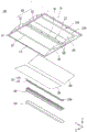
Fig. 1 is an exploded perspective view of a lighting device according to an embodiment.
Fig. 2 is an assembled perspective view of the lighting device of fig. 1.
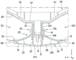
Fig. 3 is a side cross-sectional view of the lighting device of fig. 1.
Fig. 4 is a partial enlarged view of the lighting device of fig. 2.
Fig. 5 is an exploded perspective view of the heat sink and the front cover of fig. 1.
Fig. 6 is a partially enlarged view of the heat sink and the front cover of fig. 1.
Fig. 7 is an assembled perspective view of the heat sink and the front cover of fig. 5.
Fig. 8 is an enlarged view of the first rear cover of the lighting device of fig. 3, showing a comparison of the respective reflection areas in the first recess.
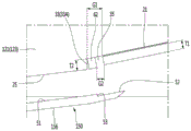
Fig. 9 is an enlarged view of a first rear cover of the lighting device of fig. 3.
Fig. 10 is a view illustrating a first reflection sheet and a third reflection sheet on the first back cover of fig. 9.
Fig. 11 is a view illustrating an optical path of the third reflection sheet in the first rear cover of the lighting device of fig. 9.
Fig. 12 is a partially enlarged view of fig. 11 for explaining a problem caused by a gap between the light-transmitting sheet and the top surface of the concave portion.
Fig. 13 is a cross-sectional view taken along line a-a of the lighting device of fig. 2.
Fig. 14 is a side sectional view showing a combination of a heat sink and a front cover in a case according to an embodiment.
Fig. 15 to 17 are views showing another example of the front cover according to the embodiment.
Fig. 18 is a view showing a locking pawl disposed on an inner side wall of the housing of fig. 1.
Fig. 19 is a perspective view of the housing of fig. 1 prior to attachment of the front cover.
Fig. 20 is a view showing locking claws and a light-transmitting piece in an inner side wall of the housing in fig. 19.
Fig. 21 is a view showing a front cover and a light-transmitting sheet on a locking claw of the housing in fig. 19.
Fig. 22 is a partially enlarged view of fig. 21.
Fig. 23 is a view showing an example in which a light-transmitting sheet and a front cover are attached to the locking claw in fig. 19.
Fig. 24 is a view showing a locking claw, a light-transmitting sheet, and a front cover of the housing in fig. 23.
Fig. 25 is a view showing an example in which both end portions of the light-transmitting sheet are combined in fig. 19.
Fig. 26 is a partially enlarged view of fig. 25.
Fig. 27 is a side sectional view illustrating a Light Emitting Diode (LED) according to an embodiment.
Detailed Description
Hereinafter, preferred embodiments of the lighting device according to the embodiments will be described with reference to the accompanying drawings. The terms described below are terms defined in consideration of functions in the present embodiment, and may be changed according to the intention or practice of a user or operator. Accordingly, such terms should be defined based on the entire disclosure herein. In addition, the following embodiments are not intended to limit the scope of the present invention, but are presented only as examples, and there may be various embodiments implemented by technical ideas.
Hereinafter, preferred embodiments of the present invention will be described in more detail with reference to the accompanying drawings. Meanwhile, the term "lighting module or lighting device" used herein refers to a lighting device used indoors or outdoors, and is definitely used in advance as a generic term for similar devices such as a flat lamp, a luminaire, a street lamp, various illumination lamps, an electronic bulletin board, a head lamp, and the like.
Fig. 1 is an exploded perspective view of a lighting device according to an embodiment, fig. 2 is an assembled perspective view of the lighting device of fig. 1, fig. 3 is a side sectional view of the lighting device of fig. 1, fig. 4 is a partially enlarged view of the lighting device of fig. 2, fig. 5 is an exploded perspective view of a heat sink and a front cover of fig. 1, fig. 6 is a partially enlarged view of the heat sink and the front cover of fig. 1, and fig. 7 is an assembled perspective view of the heat sink and the front cover of fig. 5.
Referring to fig. 1 to 7, the lighting device 100 includes: a case 110 having rear covers 111 and 112, the rear covers 111 and 112 having recesses 115 and 115A whose lower portions are opened; a heat sink 150 disposed at a lower portion of the center of the rear covers 111 and 112; light emitting modules 170 and 170A, the light emitting modules 170 and 170A being disposed on the heat sink 150; and light-transmitting sheets 180 and 182, the light-transmitting sheets 180 and 182 being disposed on the concave portions 115 and 115A of the rear covers 111 and 112.
Referring to fig. 1 to 3, the case 110 includes rear covers 111 and 112 having recesses 115 and 115A, lower portions of the recesses 115 and 115A being convexly recessed upward. The rear covers 111 and 112 may include first and second rear covers 111 and 112 that are symmetrical about a center line in the second Z-axis direction. The concave portions 115 and 115A may have shapes symmetrical to each other with respect to a center line in the second Z-axis direction at a lower portion of the center side of the case 110. The second Z-axis direction may be a central axis direction. The rear covers 111 and 112 and the concave portions 115 and 115A may be arranged in a shape symmetrical in the first X-axis direction with respect to a center line in the second axis direction. The first X-axis direction may be perpendicular to the second Z-axis direction on the same horizontal plane. The direction orthogonal to the first X-axis direction and the second Z-axis direction may be a height direction or a thickness direction and a third Y-axis direction.
The concave portions 115 and 115A may include a first concave portion 115 and a second concave portion 115A, the first concave portion 115 and the second concave portion 115A being arranged on both sides in the first axial direction with respect to the second Z-axis direction of the center side of the housing 110. A lower portion of the first rear cover 111 may be opened at the first recess 115, and a lower portion of the second rear cover 112 may be opened at the second recess 115A. The first rear cover 111 may have a first recess 115 at a lower portion of the first rear cover 111, and the second rear cover 112 may have a second recess 115A at a lower portion of the second rear cover 112. The first and second concave portions 115 and 115A are convex upward in the X-Z plane, and the first and second rear covers 111 and 112 may be disposed on the outer peripheries of the first and second concave portions 115 and 115A.
The inner surfaces of the first and second rear covers 111 and 112 may include concave portions 115 and 115A having a parabolic shape or an elliptical shape. The outer shapes of the first and second rear covers 111 and 112 may include a plurality of parabolic shapes, a plurality of elliptical shapes, a hyperbolic shape, or a pair of curved surfaces, but are not limited thereto. A heat dissipation member (e.g., a heat sink 150) may be disposed in a region between the first recess 115 and the second recess 115A. The first rear cover 111 and the second rear cover 112 may be line-symmetrical in shape with respect to the second Z-axis direction on the center side. A power supply device (not shown) may be provided on the rear covers 111 and 112, but is not limited thereto.
The housing 110 may have two sidewalls of the recesses 115 and 115A, and the two sidewalls may be disposed to face each other with respect to the second Z-axis direction. A reflective material or a reflective sheet (not shown) may be further disposed on inner surfaces of both sidewalls of the recesses 115 and 115A for reflecting light, but it is not limited thereto. The depth of the recesses 115 and 115A may be formed deeper toward the central regions of the rear covers 111 and 112. The first recess 115 and the second recess 115A may be different illumination areas.
Referring to fig. 2 and 3, when viewed in the XZ plane, in the case 110, a length X1 in the first X-axis direction and a length Z1 in the second Z-axis direction may be the same as or different from each other. The length X1 may have a relationship of X1 ≧ Z1, or may have a relationship of X1 ≦ Z1. When the length X1 is different from the length Z1, the difference may be 5 times or less.
The thickness Y1 or height of the housing 110 may be 1/10 or less of the length in the first X-axis direction and/or the second Z-axis direction, and may be, for example, in the range of 49 to 59 mm. The thickness Y1 of the case 110 may be arranged to be 1/10 or less of the length in the first X-axis direction and/or the second Z-axis direction, so that a lighting device having a thin thickness can be provided. The first X-axis direction is a lateral direction or a width direction of the housing 110, and the second Z-axis direction is an axial direction orthogonal to the first X-axis direction. The third Y-axis direction may be a height or thickness direction. Here, the size X1 × Z1 of the lighting device is 550 to 600mm × 550 to 600mm, and the thickness or height Y1 may be in the range of 50 to 52mm, but is not limited thereto.
The receiving protrusions 113 may be disposed at both edges 114 of the case 110, and the receiving protrusions 113 may be coupled to another structure such as a ceiling. The receiving protrusion 113 may have a step structure or a locking claw structure with respect to the rim 114, or may have a protruding structure protruding further in an outward direction. As shown in fig. 3, a plurality of fastening holes 105 may be disposed in the first and second rear covers 111 and 112 of the case 110 so as to be fastened to other structures.
As shown in fig. 1 and 3, the connection portion 117 may be disposed in an area between the first rear cover 111 and the second rear cover 112. The connection portion 117 may be disposed in a region between the outer curved surface of the first rear cover 111 and the outer curve of the second rear cover 112. The upper surface of the connection portion 117 may be disposed lower than the outer surfaces of the first and second rear covers 111 and 112. The connection portion 117 may be formed in the second Z-axis direction or the central axis direction of the case 110. One or more fastening protrusions 90 may protrude from the connection part 117, and the fastening protrusions 90 may be components such as pillars or fastening members such as screws or rivets. The connection portion 117 may be provided with a fastening hole into which a fastening portion such as a screw is inserted, but is not limited thereto. Since the fastening protrusion 90 is coupled through the heat sink 150, the movement of the heat sink 150 may be suppressed. The upper surface of the connecting portion 117 may be a plane, such as a horizontal plane. When the upper surface of the connection portion 117 is a plane, a contact area with other structures may be increased, or structures such as a power supply device may be easily adhered or fixed. The thickness of the connection portion 117 may be formed to be greater than the thickness of the first and second rear covers 111 and 112. The thickness of the first and second rear covers 111 and 112 is the distance between the upper surfaces of the recesses 115 and 115A and the outer curved surfaces of the rear covers 111 and 112. The connection portion 117 may support the heat sink 150 and may be coupled to a power supply device.
The case 110 (e.g., the rear covers 111 and 112) may include a plastic material, and may include at least one of Polycarbonate (PC), polyethylene terephthalate glycol (PETG), Polyethylene (PE), polystyrene paper (PSP), polypropylene (PP), and polyvinyl chloride (PVC), for example.
The rear covers 111 and 112 may have a material whose reflectance is higher than transmittance, and may be a material having reflectance of 70% or more, for example, 80% or more. Light incident on the surfaces of the rear covers 111 and 112 may be reflected by increasing the reflectivity of the rear covers 111 and 112. The back covers 111 and 112 may be a material having a light absorption rate of 20% or less, for example, 15% or less, but it is not limited thereto. The rear covers 111 and 112 may be added with metal oxide in a resin material such as silicone or epoxy. The rear covers 111 and 112 are formed of a white resin material, thereby improving the reflection efficiency of light.
The heat sink 150 may be disposed in the second Z-axis direction below the third Y-axis direction of the case 110. The heat sink 150 may be disposed on an opposite region of the connection portion 117 of the case 110. The heat sink 150 may be arranged in the Z-axis direction in a region between the first recess 115 and the second recess 115A. The heat sink 150 may be disposed in a region overlapping the connection portion 117 of the case 110 in the Y-axis direction. The heat sink 115 may be disposed above the level of the lower surface of the housing 110 or may be disposed in a non-protruding configuration. The heat sink 150 may be bar-shaped.
The heat sink 150 may be made of a metal material, and may include, for example, at least one of metals such as aluminum, copper, nickel, and silver, but is not limited thereto. The heat spreader 150 may include a carbon material, but is not limited thereto.
Referring to fig. 3 to 6, the heat sink 150 includes heat dissipation portions 151 and 151A arranged on opposite sides of each other with respect to the third Y-axis direction and reflectors 153 and 153A protruding in opposite directions to each other at lower portions of the heat dissipation portions 151 and 151A.
The heat dissipation portions 151 and 151A may have vertical surfaces in the direction of the recesses 115 and 115A, and the vertical surfaces may include flat surfaces. The vertical surface may correspond to each of the light-transmitting sheets 180 and 182. The heat sink members 151 and 151A may include a first heat sink member 151 disposed on an inner side of the first recess 115 and a second heat sink member 151A disposed on an inner side of the second recess 115A. The first and second heat sink pieces 151 and 151A may be arranged in opposite directions to each other with respect to the heat sink 150. The first heat sink member 151 may have a vertical surface in the Y-axis direction inside the first recess 115 and the second heat sink member 151A may have a vertical surface in the Y-axis direction inside the second recess 115A. The vertical surfaces of the first and second heat sink members 151 and 151A may be flat surfaces and arranged at right angles to the first X-axis direction in the third Y-axis direction or the thickness direction.
The heat sink 150 may have heat dissipation holes 159, and the heat dissipation holes 159 may be arranged in the second Z-axis direction. The heat dissipation holes 159 may be arranged in the same axial direction as that in which the Light Emitting Diodes (LEDs) 173 are arranged. The side section of the heat dissipation hole 159 may be polygonal or circular, but it is not limited thereto. The heat dissipation holes 159 may be provided at both ends with an open structure, as shown in fig. 6. Such heat dissipation holes 159 may provide a vertical or horizontal path through which heat conducted from the first and second heat dissipation parts 151 and 151A may be transferred. The heat sink 150 may include an upper frame 159A disposed above the heat dissipation holes 159 and a lower frame 159B disposed below the heat dissipation holes 159. The upper frame 159A and the lower frame 159B may be bent or coupled from the first heat sink member 151 and the second heat sink member 151A.
The heat dissipation holes 159 may be disposed in regions between the first and second heat dissipation parts 151 and 151A and the upper and lower frames 159A and 159B. In the upper frame 159A and the lower frame 159B, a plurality of insertion holes 91 penetrate in the Y-axis direction, and fastening protrusions of fig. 1 of the housing 110 may be inserted into the plurality of insertion holes 91. In the front cover 155 corresponding to the insertion hole 91, the fastening hole 92 may be arranged along the fixing frame 157 as shown in fig. 6. Accordingly, the fastening part 19 on the case 110 of fig. 1 may be used to be fastened to the fastening hole 92 of the front cover 155 via the fastening protrusion 91.
The light emitting modules 170 and 170A may be arranged on the heat sink 150 in the Z-axis direction. The light emitting modules 170 and 170A may be coupled to opposite sides of the heat sink 150 in the X-axis direction. The light emitting modules 170 and 170A may have a long length in the longitudinal direction of the heat sink 150. The light emitting modules 170 and 170A emit light in different directions of the recesses 115 and 115A.
The light emitting modules 170 and 170A may be disposed on vertical surfaces of the heat dissipation parts 151 and 151A of the heat sink 150. The light emitting modules 170 and 170A include a plurality of light emitting modules, and may include, for example, a first light emitting module 170 and a second light emitting module 170A. The first light emitting module 170 is disposed in a first region of the heat sink 150 corresponding to the first recess 115, and the second light emitting module 170A may be disposed in a second region of the heat sink 150 corresponding to the second recess 115A. The first light emitting module 170 emits light through the first recess 115, and the second light emitting module 170A emits light through the second recess 115A. The first light emitting module 170 may be disposed in the first heat sink member 151, and the second light emitting module 170A may be disposed in the second heat sink member 151A.
Some of the light emitted from the first and second light emitting modules 170 and 170A may be reflected, and some of the light may be irradiated to the light transmissive sheets 180 and 182. When light emitted in a horizontal direction from the first and second light emitting modules 170 and 170A is irradiated to the light transmitting sheets 180 and 182, this may be defined as direct illumination. When the reflected light strikes the light transmissive sheets 180 and 182, it can be defined as indirect illumination. One or more light transmissive sheets 180 and 182 may be disposed. The light-transmitting sheets 180 and 182 may include a first light-transmitting sheet 180 disposed on the first recess 115 and a second light-transmitting sheet 182 disposed on the second recess 115A.
As shown in fig. 4, the reflectors 153 and 153A may have predetermined curvatures on opposite sides from the heat dissipation parts 151 and 151A, respectively, and extend in opposite directions to each other. The reflectors 153 and 153A may be disposed at lower portions of the heat dissipation parts 151 and 151A. The reflectors 153 and 153A may integrally extend from the heat dissipation portions 151 and 151A. The reflectors 153 and 153A may include a plurality of reflective regions having surfaces with different radii of curvature and reflecting incident light. The reflectors 153 and 153A include a first reflector 153 and a second reflector 153A extending from each of the heat dissipation portions 151 and 151A.
The front cover 155 is disposed at a lower portion of the heat sink 150. The front cover 155 may be coupled to a lower portion of the heat sink 150. The front cover 155 may overlap the heat sink 150 in the Y-axis direction and may be disposed along the heat sink 150 in the Z-axis direction. The front cover 155 may prevent a lower region of the heat sink 150 from being exposed. The width of the front cover 155 in the X-axis direction may be greater than a gap between the first and second light emitting modules 170 and 170A. The width of the front cover 155 in the horizontal direction may be wider than the width of the connection portion 117 in the X-axis direction. Such a front cover 155 may cover a lower region between the concave portions 115 and 115A.
The first reflector 153 is disposed between the first heat sink piece 151 and the front cover 155, and the second reflector 153A is disposed between the second heat sink piece 151A and the front cover 155. The front cover 155 may be disposed at lower portions of the first and second reflectors 153 and 153A to prevent lower surfaces of the first and second reflectors 153 and 153A from being exposed to the outside. Each edge of the first and second reflectors 153 and 153A may be disposed on an area corresponding to both edges of the front cover 155.
The first reflector 153 and the second reflector 153A may have a curved shape. The inner surfaces of the first and second reflectors 153 and 153A may have curved surfaces. The first reflector 153 may extend from the first heat sink member 151 to the outside of the lower end portion of the first light-transmitting sheet 180. The second reflector 153A may extend from the second heat sink piece 151A to the outside of the lower end of the second light-transmitting sheet 182. The inner surface of the first reflector 153 may include reflective regions having different radii of curvature, and the inner surface of the second reflector 153A may include reflective regions having different radii of curvature. The inner surfaces of the first and second reflectors 153 and 153A may be arranged in the direction of the first and second recesses 115 and 115A.
An upper end of the first reflector 153 may be disposed at a lower portion of the first light emitting module 170, and an upper end of the second reflector 153A may be disposed at a lower portion of the second light emitting module 170. The first and second reflectors 153 and 153A are adjacent to lower portions of the first and second light emitting modules 170 and 170A, and reflect side light transmitted downward from the light emitted from the LEDs 173. The reflected light may be transmitted to the light-transmitting sheets 180 and 182 and the inner surfaces of the rear covers 111 and 112. The third reflective sheet 162 may be disposed on the inner surfaces of the reflectors 153 and 153A, or the inner surfaces may be coated with a reflective material or a metal surface of the heat sink 150 may be exposed. The upper end portions of the reflectors 153 and 153A may overlap the LEDs 173 of the light emitting modules 170 and 170A in the vertical direction, thereby effectively reflecting incident light.
Referring to fig. 4, 6 and 7, the heat sink 150 may include reflection frames 154 and 154A on an outer side of an upper portion thereof, and the reflection frames 154 and 154A may protrude more outward than the upper frame 159A. The reflective frames 154 and 154A may be bent in an outward direction, for example, in the first and second recess directions, from the upper portions of the first and second heat sink pieces 151 and 151A. The reflective frames 154 and 154A may overlap the light emitting modules 170 and 170A in a vertical direction and may reflect light emitted from the LEDs 173 in an upward direction. The reflective frames 154 and 154A may cover upper regions of the first and second light emitting modules 170 and 170A. The reflection frames 154 and 154A may closely contact the lower surface of the center-side connection part 117 of the case 110 or be coupled to the lower surface of the center-side connection part 117 of the case 110. A groove 117A may be provided on a lower surface of the center-side connection portion 117 so that the reflection frames 154 and 154A may be inserted into the groove 117A. The upper and outer surfaces of the reflection frames 154 and 154A may be in contact with the groove 117A.
Referring to fig. 4 to 7, the front cover 155 may be disposed under the heat sink 150. The front cover 155 may include a metallic material or a non-metallic material, and may be coupled to the heat sink 150. When the front cover 155 is a metal material, heat conducted from the heat sink 150 may be dispersed to the outside. When the heat sink 150 is a non-metal material, for example, a plastic material, the design of the front cover 155 may be variously changed.
The front cover 155 may include a fixing frame 157 disposed under a lower frame 159B of the heat sink 150 and a cover plate 156 disposed under the fixing frame 157.
The fixing frame 157 of the front cover 155 may have a plurality of fastening holes 92 and may be inserted into the receiving groove 153B of the lower frame 159B of the heat sink 150, and the fastening members 19 of fig. 1 fastened via the heat sink 150 may be fastened to the fastening holes 92. Accordingly, the front cover 155 may be fixed to the heat sink 150, and the heat sink 150 may be fixed to the case 110. The cover plate 156 of the front cover 155 may extend into the areas of the first and second recesses 115 and 115A. The cover plate 156 may be formed as a curved surface or an inclined surface on an upper surface or a lower surface thereof. The cover plate 156 may be formed in a symmetrical shape with respect to a center line in the second Z-axis direction.
As shown in fig. 4 and 6, the heat sink 150 may include light leakage preventing protrusions 62 protruding from the end portions 61 of the first and second reflectors 153 and 153A in the front cover direction or the downward direction. The end portions 61 of the first and second reflectors 153 and 153A and the cover plate 156 of the front cover 155 are spaced apart from each other, a region between the end portions 61 of the first and second reflectors 153 and 153A and the cover plate 156 may be provided with locking grooves 158, and lower end portions of the light-transmitting sheets 180 and 182 may be disposed in the locking grooves 158, respectively. The light leakage preventing protrusions 62 may be disposed to face one sides of the light transmitting sheets 180 and 182, respectively.
As shown in fig. 1, 4 and 7, each of the light emitting modules 170 and 170A includes a circuit board 171 and a plurality of LEDs 173 disposed on the circuit board 171. The circuit board 171 may stand upright in the third Y-axis direction and have a long length in the second Z-axis direction. The plurality of LEDs 173 may be arranged in the longitudinal direction or the second Z-axis direction of the circuit board 171. The first and second light emitting modules 170 and 170A may be arranged in opposite directions to each other in a region between the first and second recesses 115 and 115A.
The circuit board 171 may be disposed lengthwise along the longitudinal direction (Z-axis direction) of the heat sink 150 on the heat sink portions 151 and 151A. One or more circuit boards 171 may be disposed on the heat dissipation portions 151 and 151A, but are not limited thereto. The circuit board 171 may be arranged in one or more on each of the heat dissipation portions 151 and 151A. The circuit board 171 may be fastened with screws and/or adhered to the heat dissipation portions 151 and 151A with an adhesive, but is not limited thereto. The circuit board 171 may include, for example, a Printed Circuit Board (PCB). The PCB includes at least one of a resin material PCB, a metal core PCB (mcpcb), and a flexible PCB (fpcb), and may be provided as a metal core PCB for heat dissipation, for example.
The LED173 may emit at least one of blue light, red light, green light, white light, and UV light as a package in which a light emitting chip is packaged, and for example, may emit white light for illumination. The LED173 may be mounted on the circuit board 171 in the form of a chip, and in this case, the direction angle of the LED173 may be 115 degrees or more, for example, 118 degrees or more, but it is not limited thereto. Such an orientation angle of the LED173 may vary according to the structure of the package or the shape of the cavity in the package, but is not limited thereto. The LEDs 173 may be arranged on the circuit board 171 in one or two or more rows, but is not limited thereto.
The LEDs 173 according to the embodiment may include, for example, a warm white LED and a cool white LED on each circuit board 171. The warm white LED and the cool white LED are elements emitting white light. Since the warm white LED and the cold white LED can emit white light of mixed light by radiating a correlated color temperature, a Color Rendering Index (CRI) close to natural sunlight becomes high. Therefore, the color of the actual object can be prevented from being deformed, thereby reducing the fatigue of the eyes of the user.
As shown in fig. 3, the first light-transmitting sheet 180 may be disposed on the first recess 115, and the second light-transmitting sheet 182 may be disposed on the second recess 115A. The first light-transmitting sheet 180 may be inclined with respect to the X-axis direction. The second light-transmitting sheet 182 may be inclined with respect to the X-axis direction. The first and second light-transmitting sheets 180 and 182 may have the same angle in the X-axis direction with respect to the center between the first and second concave portions 115 and 115A. The first light-transmitting sheet 180 may be disposed above a horizontal X-Z plane of the bottom of the first recess 115. The second light-transmitting sheet 182 may be disposed above the horizontal X-Z plane of the bottom of the first recess 115A.
Upper end portions of the first and second light-transmitting sheets 180 and 182 may be disposed higher than lower end portions of the first and second light-transmitting sheets 180 and 182. The lower end portions of the first and second light-transmitting sheets 180 and 182 may be disposed closer to the heat sink 150 than the upper end portions. The first and second light-transmitting sheets 180 and 182 may have gradually higher heights as the first and second light-transmitting sheets 180 and 182 are distant from the heat sink 150.
The first recess 115 has a first protrusion 125 on the inner side, and the first protrusion 125 may protrude in an inward direction of the first recess 115 or in a direction of the heat sink 150. The first protrusion 125 may be formed lengthwise in the Z-axis direction. The first protrusion 125 and the second protrusion may have a first groove 118 at their upper portions. The second recess 115A has a second protrusion 125A on the inner side, and the second protrusion 125A may protrude in an inward direction of the second recess 115A or in a direction of the heat sink 150. The second protrusion 125A may be formed lengthwise in the Z-axis direction.
The first protrusion 125 and the second protrusion 125A may be disposed at predetermined positions on the inner surfaces of the first recess 115 and the second recess 115A, and may be disposed, for example, at the outer side of the centers of the first recess 115 and the second recess 115A. The first and second protrusions 125 and 125A protrude from the upper surfaces of the rear covers 111 and 112 in the direction of the first and second recesses 115 and 115A. The first protrusion 125 and the second protrusion 125A may be arranged along the second Z-axis direction along the center of the upper surface of the first recess 115 and the second recess 115A. The first and second protrusions 125 and 125A may be disposed in the outer circumferences of the upper ends of the first and second light-transmitting sheets 180 and 182. The first protrusion 125 and the second protrusion 125A may have the same material as the first rear cover 111 and the second rear cover 112 or a different material, and are not limited thereto.
The upper end of the first light-transmitting sheet 180 may be placed on the first protrusion 125 of the first recess 115. The upper end of the first light-transmitting sheet 180 may be inserted into the first groove 118. The lower end of the first light-transmitting sheet 180 may be disposed in the second groove 158 between the first reflector 153 and the front cover 155 of the heat sink 150. The second groove 158 may be formed by the first reflector 153 and the front cover 155 of the heat sink 150. The upper end portion of the second light-transmitting sheet 182 may be placed on the second protrusion 125A of the second recess 115A. An upper end portion of the second light-transmitting sheet 182 is disposed in the first groove 118, and a lower end portion of the second light-transmitting sheet 180A may be disposed in the second groove 158 between the second reflector 153A of the heat sink 150 and the front cover 155. The second groove 158 may be formed by the second reflector 153A and the front cover 155 of the heat sink 150.
The light-transmitting sheets 180 and 182 may be sheets having a diffusion agent or may include a diffusion sheet material. The light-transmitting sheets 180 and 182 may include a diffusion sheet, for example, at least one of Polymethylmethacrylate (PMMA), polypropylene (PP), Polyethylene (PE), and Polystyrene (PS).
The light-transmitting sheets 180 and 182 may include a plurality of layers, such as a diffusion film and a diffusion plate on the diffusion film. The diffusion film may include at least one of polyethylene terephthalate (PET), PS, and PC, and the diffusion plate may include at least one of PC, PS, and PMMA. The diffusion film diffuses incident light, and the diffusion plate has a thickness greater than that of the diffusion film, diffuses light passing through the diffusion film and prevents sagging.
Since the first recess 115 of the first rear cover 111 is arranged in the same structure as the second recess, the structure of the second recess will be omitted hereinafter, and only the first recess will be described. The second recess and the second light-transmitting sheet will be described with reference to the description of the first recess and the first light-transmitting sheet.
Referring to fig. 8 and 9, the first light-transmitting sheet 180 may be disposed in an oblique direction oblique to the optical axis X0. The optical axis X0 may be an axial direction perpendicular to the emitting surface of the LED 173. The optical axis X0 may be parallel to the first X-axis direction.
Here, an upper end portion of the first light transmission sheet 180 may be disposed on the first protrusion 125, and a lower end portion of the first light transmission sheet 180 may be disposed on the cover plate 156 of the front cover 155. The front cover 155 or the cover plate 156 may be disposed at a position lower than the first protrusion 125.
The first light-transmitting sheet 180 may be inclined at a predetermined angle θ 1 with respect to the X-axis direction of the housing 110. The light transmissive sheet 180 may be disposed in a shape inclined with respect to the optical axis X0 in the first concave portion 115 of the first rear cover 111. The inclination angle θ 1 of the first light transmission sheet 180 may be 45 degrees or less with respect to the X-axis direction of the housing 110. The angle θ 1 may be inclined in a range of 9 to 13 degrees, for example, in a range of 11 to 12 degrees with respect to the optical axis X0. When the inclination angle θ 1 of the first light-transmitting sheet 180 is not within the above range, the distribution of light reflected in the concave portion 115 may not be uniform, and a uniform luminance distribution may not be provided by light directly incident on the first light-transmitting sheet 180. Such a light-transmitting sheet 180 may correspond to the LED173 in the horizontal direction by being inclined at an angle θ 1. The first light-transmitting sheet 180 may receive and diffuse light reflected via the surface of the first concave portion 115 to irradiate the light.
The light emitting surface of the LED173 or the rear surface of the circuit board 171 may be arranged at a right angle or in a range of 89 to 91 degrees with respect to the first X axis. Therefore, light emitted from the LED173 may be directly irradiated onto the entire regions B1, B2, and B3 of the first light-transmitting sheet 180. The first light-transmitting sheet 180 may directly receive and diffuse light emitted from the LED173 through the inclination angle θ 1. As another example, when the LED173 is not at the angle with respect to the first X axis, light emitted from the LED173 may not be irradiated to a partial area of the first light-transmitting sheet 180, and the reflected light may be used.
Referring to fig. 8 to 10, in the first recess 115, reflection regions M1, M2, and M3 for changing a path of light emitted from the LED173 may be arranged, or reflection sheets 160 and 165 may be attached on at least one of the reflection regions M1, M2, and M3.
The inner surface of the rear cover 111 may have a plurality of reflective regions M1 and M2 disposed between the LEDs 173 and the upper end of the light-transmissive sheet 180. The reflective regions M1 and M2 may include a first reflective region M1 adjacent to the LED173 and a second reflective region M2 disposed between the first reflective region M1 and the upper end of the light-transmissive sheet 180.
The first reflection area M1 may be a section from the highest point of the first recess 115 to a point adjacent to the LED173 on the inner side surface of the first recess 115. The second reflection area M2 may be a section from the highest point of the first concave portion 115 to a point adjacent to the upper end of the light-transmitting sheet 180 on the inner side surface of the first concave portion 115. That is, the boundary between the first and second reflection regions M1 and M2 may be the highest point portion of the first concave portion 115, but is not limited thereto.
The first reflection region M1 may reflect the first side light L1 of the light emitted from the LED173 to the second reflection region M2. The second reflective region M2 may reflect light emitted from the LED173 and light reflected from the first reflective region M1 to the light transmissive sheet 180. The first reflection region M1 may include a plurality of reflection surfaces or inclined surfaces having different radii of curvature. The second reflection region M2 may include a plurality of reflection surfaces or planes having different radii of curvature.
Referring to fig. 8 and 9, the first reflection region M1 is a regular reflection region, and the second reflection region M2 is an irregular reflection region for incident lights L1, L2, and L3. The first and second reflection regions M1 and M2 may be arranged above the optical axis X0. In addition, the locking protrusion 125 may be spaced apart from the optical axis X0 by a predetermined distance d 1.
The first and second reflection regions M1 and M2 may be arranged in a direction angle region with respect to the optical axis X0 of the LED 173. Both ends of the first reflective area M1 may form an angle R3 ranging from 28 to 33 with the LED173 as a start point P. When the angle between both ends R3 of the first reflection region M1 and the start point P of the LED173 is greater than the above range, the light regularly reflected from the first reflection region M1 may be irradiated onto the light-transmissive sheet 180 to generate a bright line on the light-transmissive sheet 180. When the angle R3 is less than the above range, the light regularly reflected from the first reflection region M1 is not uniformly irradiated to the second reflection region M2, and thus the light distribution is not uniform. The first reflection region M1 may be arranged within an angular range that allows the right-side light L1 incident thereon to be regularly reflected to different regions of the second reflection region M2. Here, the starting point P may be the center of the emitting surface of the LED 173.
The angle R3 may be wider than an angle R4 formed by both ends of the second reflection region M2 with the LED173 as a start point P. Both ends of the second reflection region M2 may form an angle ranging from 21 to 26 degrees with the LED173 as a start point P, and the angle may be smaller than the angle R3 formed by the first reflection region M1. When both ends of the second reflection region M2 are arranged at the angle R4 with the center of the emission surface of the LED173 as the starting point P, light reflected via the first reflection region M1, light reflected via the third reflection region M3, and light emitted from the LED173 may be irregularly reflected to irradiate the entire region of the light-transmissive sheet 180. When the second reflection region M2 is greater than the angle R4, the light emission intensity may be reduced, and when the second reflection region M2 is less than the angle R4, the light uniformity may be reduced.
A starting point P of the LED173 is the center of the emission surface, and a straight line perpendicular to the emission surface may be defined as an optical axis X0. The light-transmissive sheet 180 may have a first point Px intersecting the optical axis X0, and the first point Px may be a point 1/2 or more, for example, a point 2/3, from the upper end of the light-transmissive sheet 180. In addition, the second point Py may be a point away from the upper end 1/3 of the light transmissive sheet 180.
A line from the LED173 as the starting point P to the upper end of the light-transmissive sheet 180 and a line from the LED173 as the starting point P to the first point Px may have an angle R1 of less than 10 degrees therebetween, but is not limited thereto. When the angle R1 is 10 degrees or more, a bright line may be generated by light directly incident on the light-transmitting sheet 180. The angle R1 may vary depending on the inclination angle of the light-transmitting sheet 180, but is not limited thereto.
With the LED173 as the starting point P, an angle R1+ R2 formed by both ends of the light-transmissive sheet 180 may be greater than an angle R3 or R4 formed by the first or second reflective region M1 or M2, for example, in the range of 34 to 39 degrees. When the angle R1+ R2 formed by both ends of the light-transmitting sheet 180 is less than the above range, the diffusion effect of light may be reduced and the uniformity of light may be reduced, and when the angle R1+ R2 formed by both ends of the light-transmitting sheet 180 is greater than the above range, the generation of bright lines may be increased by directly incident light.
The reflector 153 may be the third reflection region M3 and the third reflection region M3 may reflect incident light to the second reflection region M2 and/or the light transmissive sheet 180. With the LED173 as the starting point P, an angle R5 formed by both ends of the lower third reflective region M3 may be greater than an angle R3 or R4 formed by the first reflective region M1 or the second reflective region M1. The third reflection area M3 may be a regular reflection area or an irregular reflection area. The third reflective region M3 may reflect incident light to the second reflective region M2 and the light-transmitting sheet 180 to suppress generation of bright lines in the light-transmitting sheet 180. The region of the third reflective region M3 adjacent to the LED173 may cover the region of the LED173 not within the directional angle range, thereby reducing light leakage.
At least one of the reflective regions M1, M2, and M3 may include a reflective sheet. For example, as shown in fig. 9 and 10, the reflective sheets 160, 165, and 162 may be disposed on the inner surface of the rear cover 111 and on the reflector 153. The reflective sheets 160, 165, and 162 may include first to third reflective sheets 160, 165, and 162 arranged in different regions.
The first reflection sheet 160 may be disposed in the first reflection region M1, and the second reflection sheet 165 may be disposed in the second reflection region M2. The third reflective sheet 162 may be disposed in the third reflective region M3. The first reflective sheet 160 may be attached to the surface of the region adjacent to the LED173 from the highest point of the recess 115 in the inner surface of each recess 115. The second reflective sheet 165 may be attached to a region adjacent to the upper end of the light transmissive sheet 180 from the highest point of the concave portions 115 in the inner surface of each concave portion 115. That is, a boundary portion between the first and second reflection sheets 160 and 165 may be a highest point portion of the concave portion 115.
The third reflective sheet 162 may be disposed adjacent to the LED173 instead of the first reflective sheet 160. The first and second reflective sheets 160 and 165 may be arranged to correspond to the light-transmissive sheet 180. As shown in fig. 8, both ends of the first reflection sheet 160 may be disposed within the range of an angle R3 with the center of the emission surface of the LED173 as a start point P, both ends of the second reflection sheet 165 may be disposed within the range of an angle R4 with the center of the emission surface of the LED173 as a start point P1, and both ends of the third reflection sheet 162 may be disposed within the range of an angle R5 with the center of the emission surface of the LED173 as a start point P2.
As shown in fig. 9 and 10, the gap G1 between the light-transmitting sheet 180 and the upper surface of the first recess 115 is narrowed toward the locking protrusion 125 with respect to the center of the upper surface of the first recess 115. Such a gap G1 may be a space in which light is mixed on the light-transmissive sheet 180.
The first reflective sheet 160 may include a different material from the second reflective sheet 165. The first reflective sheet 160 may include a regular reflective sheet or a mirror sheet, and the second reflective sheet 165 may include an irregular reflective sheet or a white sheet. The first reflective sheet 160 includes Ag and Al materials. The second reflective sheet 165 may be a white plastic material, for example, Polycarbonate (PC) or polypropylene (PP), or may include a nano-coating layer, or a metal layer or a resin layer having a pattern formed thereon.
The third reflective sheet 162 may include an irregular reflective sheet or a white sheet, or may include the same material as that of the second reflective sheet 165. As another example, the third reflective sheet 162 may include a regular reflective sheet.
Here, as shown in fig. 11 and 12, when the third reflective sheet 162 is an Ag sheet, the second side light L2 of the LED173 is incident on the third reflective sheet 162 and reflected by the third reflective sheet 162, and the lights L10 and L11 reflected from the third reflective sheet 162 may be irregularly reflected by the second reflective sheet 165. For example, some of the light L10 and L11 reflected from the third reflective sheet 162 may be sufficiently diffused through the gap G1 with the light-transmitting sheet 180 and may be incident on the light-transmitting sheet 180. However, when some of the light L10 and L11 reflected from the third reflective sheet 162 is diffused by the third reflective sheet 162 adjacent to the upper end of the light-transmissive sheet 180, the light diffusion is not performed by the narrow gap G1, and the light has an uneven distribution in the upper end region B11 of the light-transmissive sheet 180.
In one embodiment, by arranging the third reflective sheet 162 as a diffusion sheet or an irregular reflective sheet, even when the gap G1 between the light-transmitting sheet 180 and the second reflective sheet 165 is narrowed, the non-uniform distribution of light reflected from the third reflective sheet 162 in the upper end region B11 of the light-transmitting sheet 180 can be improved. As another example, the third reflective sheet 162 may include a regular reflective sheet.
Referring to fig. 8 to 10, the first, second, and third reflection sheets 160, 165, and 162 according to the embodiment may include curved surfaces having a plurality of inflection points, and such curved surfaces may be capable of reflecting light onto a desired light path.
The first and second reflection sheets 160 and 165 include a material having a light reflectivity of 90% or more, and by such a light reflectivity, incident light can be reflected without loss, and thus a light extraction effect can be improved.
Here, at least one of the first and second reflection sheets 160 and 165 may be removed, but is not limited thereto.
When the light reflected from the first and third reflection sheets 160 and 162 is irregularly reflected by the second reflection sheet 165 and is incident on the different regions B1, B2, and B3, the light transmission sheets 180 and 182 diffuse and transmit the incident light. Accordingly, it is possible to prevent bright lines from occurring in the light-transmitting sheets 180 and 182 and prevent glare by directly incident light and indirectly incident light.
The minimum distance between the center of the emitting surface of the LED173 and the first reflection sheet 160 may be 8mm or more, for example, in the range of 9 to 11 mm. When the minimum distance between the center of the emitting surface of the LED173 and the first reflection sheet 160 is less than the above range, light outside the direction angle may be incident, and thus the improvement of the reflection efficiency may not be significant. When the minimum distance between the center of the emitting surface of the LED173 and the first reflection sheet 160 is greater than the above range, the path of light reflection may be difficult to control and leakage of side light may occur.
The minimum distance between the center of the emitting surface of the LED173 and the third reflective sheet 162 may be 5mm or less, for example, in the range of 4 to 4.8 mm. When such a minimum distance is smaller than the above range, the mounting of the circuit board 171 may not be easy, and when such a minimum distance is larger than the above range, leakage of the side light may occur.
The minimum distance between the center of the emitting surface of the LED173 and the light transmissive sheet 180 may be at least twice as long as the minimum distance between the LED173 and the first reflective sheet, and for example, may be in the range of 20 to 23 cm. When the minimum distance between the center of the LED173 and the light-transmissive sheet 180 is greater than the above range, the inclination angle becomes too large, and thus it is difficult to uniformly control the light distribution. When the minimum distance between the center of the LED173 and the light-transmissive sheet 180 is less than the above range, a hot spot or a bright line may occur.
The first reflective sheet 160 may include a plurality of reflective surfaces having different radii of curvature, and the plurality of reflective surfaces may include a curved surface having a positive radius of curvature. As the distance from the LED173 increases, the radius of curvature of the plurality of reflective surfaces may become larger. The plurality of reflective surfaces may be at least three, and may include, for example, three to five surfaces. When the number of the reflection surfaces is too small, it is difficult to control the dispersion of light, and when the number of the reflection surfaces is too large, the emission intensity of the reflected light may be reduced. Each of the plurality of reflective surfaces may reflect incident light to a different region of the second reflective sheet 165.
The third reflective sheet 162 may be disposed between the lower end of the light-transmissive sheet 180 and the LED 173. The third reflective sheet 162 may be disposed between the lower end of the light transmissive sheet 180 and the front cover 155. The third reflective sheet 162 may include a plurality of reflective surfaces having different radii of curvature. The reflective surface of the third reflective sheet 162 may have a larger radius of curvature as the surface becomes distant from the LED 173.
Since the third reflective sheet 162 is disposed in a parabolic shape in a region between the LEDs 173 and the light transmissive sheet 180 to reflect incident light to the second reflective sheet 165 and the light transmissive sheet 180, the third reflective sheet 162 can uniformly irradiate light to the light transmissive sheet 180 to suppress bright lines due to the directly irradiated light.
The first and third reflective sheets 160 and 162 may irradiate light to the central region B2 of the light-transmissive sheet 180, and thus, in the central region B2, bright lines formed by main light directly irradiated from the LED173 can be reduced by the indirectly incident light.
Since the second reflection sheet 165 according to the embodiment irregularly reflects the light incident from the first reflection sheet 160 and the LEDs 173 to uniformly irradiate the central area B2 of the light-transmitting sheet 180 with the light, it is possible to suppress generation of bright lines due to the light directly incident from the LEDs 173 on the light-transmitting sheet 180. In addition, the light reflected by the third reflective sheet 162 may be irregularly reflected by the second reflective sheet 165 or may be irradiated onto the upper regions B1 and B2 of the light-transmissive sheet 180, so that bright lines caused by light directly incident on the light-transmissive sheet 180 from the LEDs 173 may be removed.
The first to third reflective sheets 160, 165 and 162 improve the uniformity of the distribution of light directly irradiated to the light transmissive sheets 180 and 182 by the LEDs 173, thereby eliminating bright lines of the light incident portion.
Reviewing the unified glare value (UGR) of the lighting device of the present invention, UGR is 19 or less, indicating that the user is not subjected to any unpleasant glare. In the CIE standard, when UGR is 21 or higher, the classified user has an unpleasant feeling.
Table 1 shows UGR, light efficiency, and light uniformity of the lighting device according to the embodiment.
[ Table 1]

Here, the lighting device has a size of 550 to 600mm × 550 to 600mm, and a thickness or height range of 50 to 52 mm. The orientation angle of the LED may also be in the range of 120 degrees ± 5%.
Referring to fig. 1 and 13, a plurality of fastening protrusions 90 may be arranged at predetermined intervals in the Z-axis direction in a central region of the housing 110, and the fastening protrusions 90 may protrude in the downward direction of the Y-axis. The center side interval K1 may be narrower or wider than the side interval K2 in the intervals K1 and K2 between the plurality of fastening protrusions 90, but is not limited thereto. The front cover 155 may be fixed to the case 110 together with the heat sink 150 by the fastening protrusions 90.
Fig. 14 to 16 are other examples of the front cover according to the embodiment.
Referring to fig. 14, the front cover 155 includes a fixing frame 157 and a cover plate 156 extending in two lateral directions under the fixing frame 157.
The fixing frame 157 has a fastening hole and may be fastened to the case 110 together with the heat sink 150 of fig. 14 by a fastening part 19. The fixing frame 157 may have a space 157A in which a lower portion of the fastening part 19 is disposed.
The upper surface 70 of the cover plate 156 may have an inclined surface, and the lower surface of the cover plate 156 may be provided with a plurality of concave- convex structures 71 and 72. The inclined upper surface 70 may extend to contact below the lower ends of the light transmissive sheets 180 and 182 of fig. 12 toward an outward direction (e.g., X-axis direction) from the center of the cover plate 156. That is, the inclination angle of the upper surface 70 of the cover plate 156 may be the same as the inclination angle θ 1 of the light transmissive sheet 180 of fig. 9. As another example, an outer portion of the step structure 70A in the upper surface 70 of the cover plate 156 may be arranged at the same angle as the inclination angle θ 1 of the light transmissive sheet 180, and an inner portion of the step structure 70A may be arranged at a different angle from the inclination angle θ 1 of the light transmissive sheet 180, for example, may be arranged at an angle smaller or larger than the angle θ 1.
The lower portion of the cover plate 156 may include an inner region C1 and an outer region C2 having the concavo- convex structures 71 and 72. The inner side region C1 may be provided as a flat surface to ensure rigidity at the center side of the front cover 155. The flat inner side region C1 may be a region overlapping with a region of the fixing frame 157 in the vertical direction.
The step structure 70A may be disposed at the outer side of the upper surface 70 of the cover plate 156 of the front cover 155, and the step structure 70A corresponds to the light leakage preventing protrusions 62 of the reflectors 153 and 153A of the heat sink 150 shown in fig. 14, so that light leakage caused by the light transmitting sheets 180 and 182 can be reduced.
The outer side region C2 having the concave- convex structures 71 and 72 may be arranged at the outer side of the inner side region C1, may be a region that does not overlap with the fixing frame 157 in the vertical direction, and may be a region that overlaps with the concave portions 115 and 115A shown in fig. 12 in the vertical direction. The outside area C2 may become gradually thicker from the center of the cover plate 156 toward the outside.
In the concave- convex structures 71 and 72, the concave portions 71 and the convex portions 72 may be alternately arranged. The depth of the concave portions 71 in the concave- convex structures 71 and 72 gradually increases toward the outward direction, and the length of the convex portions 72 gradually increases toward the outward direction. When such a front cover 155 is provided at a lower portion thereof with the concave- convex structures 71 and 72 and is formed of a metal material, a heat dissipation surface area may be increased. The concave portion 71 and the convex portion 72 may be arranged to have the same length as the front cover 155 in the second Z-axis direction, and are not limited thereto.
Referring to fig. 15, the front cover 155 includes a fixing frame 157 and a cover plate 156 extending in opposite directions under the fixing frame 157.
Referring to fig. 16, the cap plate 156 may have a recess 73, the recess 73 being recessed toward the center of the inner side portion 74 in the direction of the heat sink 150 in fig. 14 or in an upward direction, and an outer angle θ 2 thereof may be arranged to be an obtuse angle. The outer portion 75 of the cover plate 156 may be bent from the inner portion 74 and may include a stepped structure 75A. The outer portion 75 may be bent in a downward direction of the lower end portions of the light-transmitting sheets 180 and 182 shown in fig. 14.
The outer portion 75 of the cover plate 156 is provided with a step structure 75A. The step structure 75A may correspond to the light leakage prevention protrusion 62 of the reflectors 153 and 153A of the heat sink 150 of fig. 12, may facilitate the insertion of the light transmissive sheets 180 and 182, and thus may prevent light leakage.
Referring to fig. 17, the front cover 155 includes a fixing frame 157 and a cover plate 156 disposed under the fixing frame 157. The two frames 78 and 79 may be arranged to be spaced apart from each other at a predetermined interval at the fixed frame 157. The fastening member may be fastened to the partitioned space 77.
As another example, the fixing frame 157 may include locking ribs 78A and 79A bent outward from the frames 78 and 79, and the locking ribs 78A and 79A may be locked and coupled to the lower frame 159B of the heat sink 150 shown in fig. 14.
As another example, the fixing frame 157 may have a hook structure and be coupled to the heat sink 150 of fig. 14. As another example, the heat sink 150 of fig. 14 may have a hook structure and be coupled to the housing 110 via the hook structure.
Fig. 18 is a view showing locking claws arranged on an inner side wall of the housing of fig. 1, fig. 19 is a perspective view of the housing of fig. 1 before a front cover is coupled, fig. 20 is a view showing the locking claws and a light-transmitting sheet in the inner side wall of the housing of fig. 19, fig. 21 is a view showing the front cover and the light-transmitting sheet on the locking claws of the housing of fig. 19, fig. 22 is a partially enlarged view of fig. 21, fig. 23 is a view showing an example in which the light-transmitting sheet and the front cover are coupled on the locking claws of fig. 19, and fig. 24 is a view showing the locking claws, the light-transmitting sheet, and the front cover of the housing of fig. 23.
Referring to fig. 18 and 19, the housing 110 may include first and second locking claws 121 and 123 protruding from both side walls of the first and second concave portions 115 and 115A in the Z-axis direction. The first and second locking claws 121 and 123 may be arranged to face each other with respect to the second Z-axis direction and may extend from both sides of the connecting portion 117 of the housing 110 to both sides of each of the first and second locking protrusions 125 and 125A.
Each of the locking claws 121 and 123 may include a first support part 21 arranged on both sides of the first light-transmitting sheet 180 in the second Z-axis direction, a second support part 23 arranged on both sides of the second light-transmitting sheet 180 in the second Z-axis direction, and a light leakage preventing part 25 configured to protrude from an area between the first and second support parts 21 and 23 and face one side of lower end portions of the first and second light-transmitting sheets 180 and 182.
The lower surface of the first support part 21 may be inclined along the inclination angle of the first light-transmitting sheet 180, and the lower surface of the second support part 23 may be inclined along the inclination angle of the second light-transmitting sheet 180. The light leakage preventing part 25 may be formed in a shape to contact with the inner side of the cover plate 156 of the front cover 155. The light leakage preventing parts 25 may be disposed below both sides of the front cover 155 in the second Z-axis direction.
The light leakage preventing part 25 protrudes further from the center of the housing 110 toward the lower surface of the housing 110 than the first and second support parts 21 and 23.
As shown in fig. 21 to 24, the lower surface of the light leakage preventive portion 25 may be spaced apart from the lower surface edge 114 of the housing 110, and the cover plate 156 of the front cover 155 may be disposed in the spaced apart portion. Accordingly, the cover plate 156 may extend to the lower surface of the light leakage preventive portion 25 of the locking claws 121 and 123 and the inner side of the light transmissive sheets 180 and 182, thereby reducing light leakage.
The lower surfaces of the light leakage preventing parts 25 of the locking claws 121 and 123 may be formed along the surface of the cover plate 156 of the front cover 155. As shown in fig. 21 and 22, the light leakage preventing part 25 includes a first step structure 33 having a step height T2 with respect to the lower surface of the first support part 21 and a second step structure 33A having a step height T2 with respect to the lower surface of the second support part 23.
Such first and second stepped structures 33 and 33A may have a height T2 greater than a thickness T1 of the light-transmitting sheets 180 and 182, and may face one sides of the light-transmitting sheets 180 and 182. In addition, both sides of the front cover 155 cover the lower surfaces of the light leakage preventing parts 25 of the locking claws 121 and 123, the gap 35 between the light leakage preventing part 25 and the first light transmitting sheet 180, and the gap 35A between the light leakage preventing part 25 and the second light transmitting sheet 182. Accordingly, light leaked to one side through the inside of the light-transmitting sheets 180 and 182 may be reflected by the first and second stepped structures 33 and 33A and may be blocked by the front cover 155. Therefore, light leakage can be prevented from occurring via the region between the front cover 155 and the case 110.
The cover plate 156 of the front cover 155 may be formed with a step structure 53 on the outer side 52 of the lower surface 51, and the step structure 53 may be disposed in an area between the light-transmitting sheets 180 and 182 and the light leakage preventive portion 25, or on the light leakage preventive protrusion 62 of the heat sink 150, thus being capable of blocking light emitted through one side surface of the light-transmitting sheets 180 and 182.
Referring to fig. 20 to 22, the light leakage preventing parts 25 of the locking claws 121 and 123 and the light leakage preventing protrusions 62 of the heat sink 150 may be disposed on one side of the lower end part of the light transmissive sheet 180. Since the light leakage preventing parts 25 of the locking claws 121 and 123 are arranged on the outer side wall of the housing 110, the light leakage preventing parts 25 of the locking claws 121 and 123 may be arranged further to the outside than the light leakage preventing protrusions 62 of the heat sink 150.
One side of the light-transmitting sheets 180 and 182 may have a gap G3 with the light leakage preventing parts 25 of the locking claws 121 and 123, compared to the predetermined gap 35 or 35A shown in fig. 20 and 24. As shown in fig. 20 and 23, one side of the light-transmitting sheets 180 and 182 may be spaced apart from the light leakage preventing protrusion 62 of the heat sink 150 by predetermined gaps G2 and G2< G3.
As shown in fig. 20 to 24, the gap G3 of the gaps 35 and 35A between the light leakage preventing parts 25 of the locking claws 121 and 123 and the light transmissive sheets 180 and 182 may be arranged to be wider than the gap G2 between the light leakage preventing protrusions 62 of the heat sink 150 and the light transmissive sheets 180 and 182. The gap difference G3-G2 between the gaps 35 and 35A can be generated by assembly tolerances and the light leakage into the gaps 35 and 35A can be suppressed by the light leakage preventing portions 25 and the front cover 155 of the locking claws 121 and 123.
The embodiment can prevent light leakage due to light leaking through one side of the lower end portions of the light-transmitting sheets 180 and 182 by the locking claws 121 and 123 and the front cover 155 as described above.
Referring to fig. 25 to 27, both end portions of the light-transmitting sheets 180 and 182 may be disposed in the locking grooves 118 of the locking protrusions 125 and 125A and the locking groove 158 of the front cover 155 in fig. 25. For example, upper end portions of the light- transmissive sheets 180 and 182 may be disposed on the locking protrusions 125 and 125A, respectively, and lower end portions of the light- transmissive sheets 180 and 182 may be disposed on the cover plate 156 of the front cover 155.
In the light-transmitting sheets 180 and 182, both edges in the first X-axis direction are slidably coupled along the locking protrusions 125 and 125A and the cover plate 156, and both edges in the second Z-axis direction of the light-transmitting sheets 180 and 182 may be placed between the first locking claw 121 and the second locking claw 123 shown in fig. 18.
As shown in fig. 27, the locking groove 118 on the locking protrusion 125 is formed to have a height E1 greater than the thickness T1 of the light-transmitting sheet 180, and thus the light-transmitting sheet 180 can be easily inserted. In addition, the locking protrusion 125 may protrude by a predetermined distance E2 in the direction of the first recess 115, and such a distance E2 may be higher than the height E1, and thus the light-transmissive sheet 180 can be prevented from being separated.
Upper and lower end portions of the light-transmitting sheets 180 and 182 are supported by and closely contacted with the locking claws 121 and 123 and the cover plate 156, thereby preventing light leakage from occurring.
< light emitting diode >
Fig. 27 is a sectional view illustrating a light emitting diode according to an embodiment.
Referring to fig. 27, the light emitting diode 200 includes a body 210; a first lead electrode 211 and a second lead electrode 212, at least a portion of the first and second lead electrodes 211 and 212 being disposed in the body 210; a light emitting device 101, the light emitting device 101 being electrically connected to a first lead electrode 211 and a second lead electrode 212 on a body 210; and a molding member 220, the molding member 220 surrounding the light emitting device 101.
The body 210 may be formed of at least one of a silicon material, a synthetic resin material, and a metal material. The body 210 may include a cavity formed in the body 210 and a reflection part 215 having an inclined surface at the periphery of the body 210.
The first and second lead electrodes 211 and 212 are electrically separated from each other and formed to pass through the body 210. That is, inner portions of the first and second lead electrodes 211 and 212 may be disposed in the cavity, and other portions of the first and second lead electrodes 211 and 212 may be disposed at the outside of the body 210.
The first and second lead electrodes 211 and 212 supply power to the light emitting device 101. In addition, the first and second lead electrodes 211 and 212 reflect light emitted from the light emitting device 101, thereby improving light emitting efficiency. In addition, the first and second lead electrodes 211 and 212 may be used to discharge heat generated from the light emitting device 101.
The light emitting device 101 may be disposed on the body 210 or may be formed on the first and/or second lead electrodes 211 and 212. The light emitting device 101 may be arranged as at least one LED (light emitting diode) chip. The LED chips may include light emitting diodes in a visible light band such as red, green, blue, or white, or UV light emitting diodes that emit Ultraviolet (UV) light. The phosphor layer may be further disposed on the surface of the light emitting device 101, but the present invention is not limited thereto.
The wire 216 of the light emitting device 101 may be electrically connected to at least one of the first and second lead electrodes 211 and 212, but the embodiment is not limited thereto.
The molding member 220 may surround the light emitting device 101 to protect the light emitting device 101. In addition, the molding member 220 may include a fluorescent material to change the wavelength of light emitted from the light emitting device 101. The upper surface of the molding member 220 may be flat, concave, or convex. The upper surface or the cavity region of the molding member 220 may be a light emitting surface according to an embodiment, but the present invention is not limited thereto.
A lens may be disposed on the molding member 220, but the present invention is not limited thereto.
The light emitting diode 200 may be a blue light emitting device or a white light emitting device having a high Color Rendering Index (CRI). The light emitting diode may be a light emitting device that emits white light by molding a synthetic resin containing a phosphor on a blue light emitting chip. The phosphor may include at least one of garnet (YAG, TAG), silicate, nitride, and oxynitride.
The features, structures, effects, and the like described in the embodiments are included in at least one embodiment of the present invention, and are not necessarily limited to only one embodiment. Further, the features, structures, effects, and the like illustrated in the embodiments can be combined and modified by those skilled in the art to which the embodiments belong. Therefore, it is to be understood that the present invention is not limited to these embodiments.
While embodiments have been described with reference to a number of illustrative embodiments thereof, it should be understood that numerous other modifications and embodiments can be devised by those skilled in the art that will fall within the spirit and scope of the principles of this disclosure. More particularly, various variations and modifications are possible in the component parts and/or arrangements of the subject combination arrangement within the scope of the disclosure, the drawings and the appended claims. In addition to variations and modifications in the component parts and/or arrangements, alternative uses will also be apparent to those skilled in the art.
[ Industrial Applicability ]
The embodiments may be applied to a lighting device for a flat panel.
The embodiments may be applied to a lighting device for a flat panel having Light Emitting Diodes (LEDs).
Claims (25)
1. An illumination device, comprising:
a housing having a first rear cover and a second rear cover on both sides in a first axial direction;
a first recess in which a lower portion of the first rear cover is opened;
a second recess in which a lower portion of the second rear cover is open;
a heat sink disposed between the first recess and the second recess at a lower portion of the housing along a second axial direction perpendicular to the first axial direction;
a first light emitting module having a plurality of light emitting diodes in a first region of the heat sink corresponding to the first recess;
a second light emitting module in a second region of the heat sink corresponding to the second recess and having a plurality of light emitting diodes;
a first light-transmitting sheet arranged at the first recess to be inclined with respect to the first axial direction and configured to diffuse light emitted from the first light-emitting module;
a second light-transmitting sheet arranged at the second recess to be inclined with respect to the first axial direction and configured to diffuse light emitted from the second light-emitting module; and
a front cover configured to support a lower portion of the heat sink and lower end portions of the first and second light-transmitting sheets,
wherein the front cover includes: a fixing frame protruding in a direction of the radiator at the lower portion of the radiator; and a cover plate extending from the fixing frame in a direction of the lower end portions of the first and second light transmissive sheets,
wherein the first and second light emitting modules are arranged in opposite regions to each other with respect to the heat sink,
wherein the first light emitting module emits light through the first recess on the first area of the heat sink,
wherein the second light emitting module emits light through the second recess on the second region of the heat sink, and
wherein the heat sink includes: a first heat dissipation part in which the first light emitting module is arranged; a second heat sink part in which the second light emitting module is disposed; a first reflector extending from the first heat sink portion to the lower end of the first light transmissive sheet; a second reflector extending from the second heat sink portion to the lower end of the second light-transmitting sheet; and a light leakage preventing protrusion protruding from the lower end portions of the first and second reflectors in a direction of the cover plate.
2. The illumination device of claim 1, wherein the light leakage prevention protrusion faces a portion of the first and second light-transmissive sheets.
3. The lighting device of claim 2, wherein an upper surface or a lower surface of the cover plate has a curved surface or an inclined surface.
4. The lighting device according to any one of claims 1 to 3, wherein the cover plate has a concavo-convex structure at an outer lower portion of the cover plate.
5. The lighting device according to claim 2 or 3, wherein the cover plate has a step structure at an outer side portion, and the step structure corresponds to the light leakage preventing protrusions of the first and second reflectors of the heat sink.
6. The lighting device according to any one of claims 1 to 3, comprising: first and second locking claws that protrude from both side walls in the second axial direction in each of the first and second recesses; a first locking protrusion disposed lengthwise in the second axial direction at an inner side of the first recess; and a second locking protrusion disposed lengthwise in the second axial direction at an inner side of the second recess,
wherein the first light-transmitting piece is disposed on the first and second locking claws of the first recess and on the first locking protrusion, and the second light-transmitting piece is disposed on the first and second locking claws of the second recess and on the second locking protrusion.
7. The lighting device of claim 6, wherein each of the first and second locking pawls comprises first and second supports configured to support both ends of the first and second light-transmissive sheets in the second axial direction; and a light leakage preventing part protruding from the first and second support parts and facing side surfaces of the lower end parts of the first and second light transmission sheets.
8. The lighting device of claim 7, wherein said first and second light transmissive sheets are tilted with respect to an optical axis of said light emitting diodes of said first and second light emitting modules.
9. The lighting device of any one of claims 1 to 3, wherein the front cover comprises a plastic material.
10. The lighting device of claim 2, comprising: a first reflection sheet in inner side surfaces of the first and second recesses and adjacent to the first and second light emitting modules; and
a second reflection sheet disposed between the upper end portions of the first and second light-transmitting sheets and the first reflection sheet in inner side surfaces of the first and second concave portions.
11. The illumination device of claim 10, wherein the first and second reflectors comprise a third reflector sheet comprising a plurality of reflective surfaces having different radii of curvature thereon.
12. The illumination device of claim 10 or 11, wherein the first reflective sheet comprises a regular reflective material and the second reflective sheet comprises an irregular reflective material.
13. The lighting device of claim 12, wherein the first reflector sheet has a plurality of reflective surfaces, and a radius of curvature of the plurality of reflective surfaces increases as a distance from centers of the light emitting diodes of the first and second light emitting modules becomes farther.
14. The lighting device according to claim 10 or 11, wherein a boundary portion between the first and second reflection sheets is a highest point portion of the first and second concave portions.
15. The lighting device of claim 11, wherein the third reflective sheet comprises a regular reflective material or an irregular reflective material, and the third reflective sheet is disposed closer to the light emitting diodes of the first and second light emitting modules than the first reflective sheet.
16. The lighting device according to claim 11, wherein the third reflection sheet overlaps the front cover in a vertical direction and is arranged below optical axes of the light emitting diodes of the first and second light emitting modules.
17. The lighting device of claim 10 or 11, wherein the first and second light-transmissive sheets comprise a diffuser sheet and are inclined within the first and second recesses.
18. The lighting device of claim 10 or 11, wherein each of the first and second recesses has a parabolic shape.
19. The lighting device according to claim 18, wherein the first and second light emitting modules include a circuit board on which the light emitting diodes are arranged on the first and second heat sink members, wherein the circuit board is arranged on vertical surfaces of the first and second heat sink members in the second axial direction, and the first and second light-transmitting sheets are inclined in a range of 9 to 13 degrees with respect to optical axes of the light emitting diodes of the first and second light emitting modules.
20. The lighting device of claim 19, wherein said first and second reflective sheets are disposed above optical axes of light emitting diodes of said first and second light emitting modules.
21. An illumination device, comprising:
a housing having a first rear cover and a second rear cover on both sides in a first axial direction;
a first recess in which a lower portion of the first rear cover is opened;
a second recess in which a lower portion of the second rear cover is open;
a heat sink disposed between the first recess and the second recess at a lower portion of the housing along a second axial direction perpendicular to the first axial direction;
a first light emitting module having a plurality of light emitting diodes in a first region of the heat sink corresponding to the first recess;
a second light emitting module in a second region of the heat sink corresponding to the second recess and having a plurality of light emitting diodes;
a first light-transmitting sheet arranged at the first recess to be inclined with respect to the first axial direction and configured to diffuse light emitted from the first light-emitting module;
a second light-transmitting sheet arranged at the second recess to be inclined with respect to the first axial direction and configured to diffuse light emitted from the second light-emitting module; and
a front cover configured to support a lower portion of the heat sink and lower end portions of the first and second light-transmitting sheets,
wherein the front cover includes: a fixing frame protruding in a direction of the radiator at the lower portion of the radiator; and a cover plate extending from the fixing frame in a direction of the lower end portions of the first and second light transmissive sheets,
wherein the first light-transmitting sheet is inclined in a range of 9 to 13 degrees with respect to an optical axis of the light-emitting diode of the first light-emitting module,
wherein the second light-transmitting sheet is inclined within a range of 9 to 13 degrees with respect to an optical axis of the light emitting diode of the second light emitting module,
wherein a portion of the first light-transmitting sheet corresponds to the plurality of light-emitting diodes of the first light-emitting module in a horizontal direction,
wherein a portion of the second light-transmitting sheet corresponds to the plurality of light emitting diodes of the second light emitting module in the horizontal direction, and
wherein the heat sink includes: a first heat dissipation part in which the first light emitting module is arranged; a second heat sink part in which the second light emitting module is disposed; a first reflector extending from the first heat sink portion to the lower end of the first light transmissive sheet; a second reflector extending from the second heat sink portion to the lower end of the second light-transmitting sheet; and a light leakage preventing protrusion protruding from the lower end portions of the first and second reflectors in a direction of the cover plate.
22. The lighting device of claim 21, comprising: a first reflection sheet in inner side surfaces of the first and second recesses and adjacent to the first and second light emitting modules; and
a second reflection sheet disposed between the upper end portions of the first and second light-transmitting sheets and the first reflection sheet in the inner side surfaces of the first and second concave portions; and is
Wherein the first reflective sheet includes a regular reflective material and the second reflective sheet includes an irregular reflective material,
wherein the first and second reflection sheets are disposed above optical axes of the light emitting diodes of the first and second light emitting modules.
23. The illumination device of claim 22, wherein the first and second reflectors comprise a third reflector sheet comprising a plurality of reflective surfaces having different radii of curvature thereon.
24. The lighting device of claim 23, wherein the third reflective sheet is disposed closer to the light emitting diodes of the first and second light emitting modules than the first reflective sheet,
wherein the third reflection sheet overlaps the front cover in a vertical direction and is disposed below optical axes of the light emitting diodes of the first and second light emitting modules.
25. The lighting device according to claim 23 or 24, wherein the light leakage preventing portion protrudes from lower end portions of the first and second reflectors toward the cover plate and faces a part of the first and second light-transmitting sheets.
Applications Claiming Priority (9)
| Application Number | Priority Date | Filing Date | Title |
|---|---|---|---|
| KR10-2015-0136323 | 2015-09-25 | ||
| KR1020150136323A KR102410453B1 (en) | 2015-09-25 | 2015-09-25 | Lighting apparatus |
| KR1020150136317A KR102418684B1 (en) | 2015-09-25 | 2015-09-25 | Lighting apparatus |
| KR10-2015-0136321 | 2015-09-25 | ||
| KR10-2015-0136324 | 2015-09-25 | ||
| KR10-2015-0136317 | 2015-09-25 | ||
| KR1020150136324A KR102388286B1 (en) | 2015-09-25 | 2015-09-25 | Lighting apparatus |
| KR1020150136321A KR102385942B1 (en) | 2015-09-25 | 2015-09-25 | Lighting apparatus |
| PCT/KR2016/010571 WO2017052220A1 (en) | 2015-09-25 | 2016-09-22 | Lighting device |
Publications (2)
| Publication Number | Publication Date |
|---|---|
| CN108027112A CN108027112A (en) | 2018-05-11 |
| CN108027112B true CN108027112B (en) | 2020-06-05 |
Family
ID=58386428
Family Applications (1)
| Application Number | Title | Priority Date | Filing Date |
|---|---|---|---|
| CN201680056070.6A Active CN108027112B (en) | 2015-09-25 | 2016-09-22 | Lighting device |
Country Status (3)
| Country | Link |
|---|---|
| US (1) | US10900637B2 (en) |
| CN (1) | CN108027112B (en) |
| WO (1) | WO2017052220A1 (en) |
Families Citing this family (1)
| Publication number | Priority date | Publication date | Assignee | Title |
|---|---|---|---|---|
| JP7462463B2 (en) * | 2020-04-14 | 2024-04-05 | 三菱電機株式会社 | lighting equipment |
Citations (4)
| Publication number | Priority date | Publication date | Assignee | Title |
|---|---|---|---|---|
| KR20010096949A (en) * | 2000-04-19 | 2001-11-08 | 구자홍 | Heating energy concentration structure for microwave oven reflector |
| CN202523348U (en) * | 2012-04-28 | 2012-11-07 | 北京金立翔艺彩科技股份有限公司 | Ventilated light-leak prevention mask and LED display screen |
| CN202868582U (en) * | 2012-11-16 | 2013-04-10 | 东莞市晶谷照明科技有限公司 | Non-light-leakage lens adjusting structure for light-emitting diode (LED) illumination lamp |
| CN202868417U (en) * | 2012-11-16 | 2013-04-10 | 东莞市晶谷照明科技有限公司 | Light emitting diode (LED) illumination lamp without light leak |
Family Cites Families (13)
| Publication number | Priority date | Publication date | Assignee | Title |
|---|---|---|---|---|
| JP4804429B2 (en) * | 2003-12-05 | 2011-11-02 | 三菱電機株式会社 | Light emitting device and lighting apparatus using the same |
| DE102006027207A1 (en) * | 2006-02-01 | 2007-08-02 | Zumtobel Lighting Gmbh | Ceiling mounted light, has housing forming light discharge opening enclosed by light discharge unit, which has different light radiating characteristic that is opposite to other light radiating characteristic in one of radiation areas |
| US8770781B2 (en) | 2009-06-10 | 2014-07-08 | Sharp Kabushiki Kaisha | Lighting apparatus |
| US10883702B2 (en) * | 2010-08-31 | 2021-01-05 | Ideal Industries Lighting Llc | Troffer-style fixture |
| KR101848801B1 (en) | 2010-11-12 | 2018-04-13 | 엘지이노텍 주식회사 | Lighting device |
| KR101231728B1 (en) * | 2011-01-14 | 2013-02-07 | 엘지이노텍 주식회사 | backlight unit and display apparatus using the same |
| JP5989305B2 (en) * | 2011-01-14 | 2016-09-07 | エルジー イノテック カンパニー リミテッド | Backlight unit and display device using the same |
| CN202361183U (en) * | 2011-11-08 | 2012-08-01 | 深圳市嘉泰宏实业有限公司 | Light-leaking-proof LED (Light-emitting Diode) backlight source structure |
| KR101948142B1 (en) | 2012-03-12 | 2019-02-14 | 엘지이노텍 주식회사 | backlight unit and illumination system using the same |
| KR101981717B1 (en) * | 2012-05-10 | 2019-05-24 | 엘지이노텍 주식회사 | Lighting device |
| KR20150027521A (en) * | 2013-09-04 | 2015-03-12 | 기민전자주식회사 | Ceiling Type LED Lighting Lamp |
| KR102140579B1 (en) * | 2013-10-08 | 2020-08-03 | 엘지이노텍 주식회사 | Lighting device |
| CN203980038U (en) * | 2014-08-15 | 2014-12-03 | 深圳市澳迪星电子有限公司 | Light leakage led backlight module |
-
2016
- 2016-09-22 CN CN201680056070.6A patent/CN108027112B/en active Active
- 2016-09-22 US US15/762,981 patent/US10900637B2/en active Active
- 2016-09-22 WO PCT/KR2016/010571 patent/WO2017052220A1/en active Application Filing
Patent Citations (4)
| Publication number | Priority date | Publication date | Assignee | Title |
|---|---|---|---|---|
| KR20010096949A (en) * | 2000-04-19 | 2001-11-08 | 구자홍 | Heating energy concentration structure for microwave oven reflector |
| CN202523348U (en) * | 2012-04-28 | 2012-11-07 | 北京金立翔艺彩科技股份有限公司 | Ventilated light-leak prevention mask and LED display screen |
| CN202868582U (en) * | 2012-11-16 | 2013-04-10 | 东莞市晶谷照明科技有限公司 | Non-light-leakage lens adjusting structure for light-emitting diode (LED) illumination lamp |
| CN202868417U (en) * | 2012-11-16 | 2013-04-10 | 东莞市晶谷照明科技有限公司 | Light emitting diode (LED) illumination lamp without light leak |
Non-Patent Citations (2)
| Title |
|---|
| Measurements of net change in heat flux as a result of leakage and steps on the contoured endwall of a gas turbine first stage nozzle;J.D. Piggush;《Applied Thermal Engineering》;20070331;第27卷(第4期);第722-730页 * |
| Nd_YAG激光器电光调Q偏振片漏光现象的实验研究;赵茗;《激光技术》;20030430;第27卷(第2期);第85-87页 * |
Also Published As
| Publication number | Publication date |
|---|---|
| US20190301719A1 (en) | 2019-10-03 |
| US10900637B2 (en) | 2021-01-26 |
| WO2017052220A1 (en) | 2017-03-30 |
| CN108027112A (en) | 2018-05-11 |
Similar Documents
| Publication | Publication Date | Title |
|---|---|---|
| US10400992B2 (en) | Lighting apparatus having different reflection sheets | |
| US20110096565A1 (en) | Light source apparatus | |
| US10539300B2 (en) | Lighting apparatus | |
| CN109557716A (en) | Planar light source device and display device | |
| JP2017208206A (en) | Luminaire | |
| US9726345B2 (en) | Lighting module and lighting apparatus having the same | |
| KR20220098713A (en) | Lighting apparatus | |
| CN108027112B (en) | Lighting device | |
| KR101651657B1 (en) | Lighting Apparatus | |
| JP6300147B2 (en) | Lighting device | |
| JP6041082B2 (en) | Lighting device | |
| KR101651656B1 (en) | Lighting apparatus | |
| KR102388286B1 (en) | Lighting apparatus | |
| KR102385942B1 (en) | Lighting apparatus | |
| KR102410453B1 (en) | Lighting apparatus | |
| KR20160126385A (en) | Anti-glare LED lighting device | |
| KR20130095051A (en) | Ligout source package and backlight unit including the same | |
| JP6241601B2 (en) | Lighting device | |
| CN221424716U (en) | LED lamp | |
| CN211875722U (en) | LED light source with light guide plate | |
| KR102432223B1 (en) | Lighting apparatus | |
| JP7001993B2 (en) | Optical members and lighting equipment | |
| JP6993139B2 (en) | lighting equipment | |
| KR20170137528A (en) | Lighting apparatus | |
| KR101272689B1 (en) | Lighting module |
Legal Events
| Date | Code | Title | Description |
|---|---|---|---|
| PB01 | Publication | ||
| PB01 | Publication | ||
| SE01 | Entry into force of request for substantive examination | ||
| SE01 | Entry into force of request for substantive examination | ||
| GR01 | Patent grant | ||
| GR01 | Patent grant | ||
| TR01 | Transfer of patent right |
Effective date of registration: 20210806 Address after: 168 Changsheng North Road, Taicang City, Suzhou City, Jiangsu Province Patentee after: Suzhou Leyu Semiconductor Co.,Ltd. Address before: Seoul, South Kerean Patentee before: LG INNOTEK Co.,Ltd. |
|
| TR01 | Transfer of patent right |