CN108025157B - Medical device adapter - Google Patents
Medical device adapter Download PDFInfo
- Publication number
- CN108025157B CN108025157B CN201680038648.5A CN201680038648A CN108025157B CN 108025157 B CN108025157 B CN 108025157B CN 201680038648 A CN201680038648 A CN 201680038648A CN 108025157 B CN108025157 B CN 108025157B
- Authority
- CN
- China
- Prior art keywords
- adapter
- coil
- lumen
- medical device
- distal portion
- Prior art date
- Legal status (The legal status is an assumption and is not a legal conclusion. Google has not performed a legal analysis and makes no representation as to the accuracy of the status listed.)
- Active
Links
Images


Classifications
-
- A—HUMAN NECESSITIES
- A61—MEDICAL OR VETERINARY SCIENCE; HYGIENE
- A61M—DEVICES FOR INTRODUCING MEDIA INTO, OR ONTO, THE BODY; DEVICES FOR TRANSDUCING BODY MEDIA OR FOR TAKING MEDIA FROM THE BODY; DEVICES FOR PRODUCING OR ENDING SLEEP OR STUPOR
- A61M39/00—Tubes, tube connectors, tube couplings, valves, access sites or the like, specially adapted for medical use
- A61M39/10—Tube connectors; Tube couplings
- A61M39/1011—Locking means for securing connection; Additional tamper safeties
-
- A—HUMAN NECESSITIES
- A61—MEDICAL OR VETERINARY SCIENCE; HYGIENE
- A61M—DEVICES FOR INTRODUCING MEDIA INTO, OR ONTO, THE BODY; DEVICES FOR TRANSDUCING BODY MEDIA OR FOR TAKING MEDIA FROM THE BODY; DEVICES FOR PRODUCING OR ENDING SLEEP OR STUPOR
- A61M39/00—Tubes, tube connectors, tube couplings, valves, access sites or the like, specially adapted for medical use
- A61M39/10—Tube connectors; Tube couplings
- A61M39/105—Multi-channel connectors or couplings, e.g. for connecting multi-lumen tubes
-
- A—HUMAN NECESSITIES
- A61—MEDICAL OR VETERINARY SCIENCE; HYGIENE
- A61M—DEVICES FOR INTRODUCING MEDIA INTO, OR ONTO, THE BODY; DEVICES FOR TRANSDUCING BODY MEDIA OR FOR TAKING MEDIA FROM THE BODY; DEVICES FOR PRODUCING OR ENDING SLEEP OR STUPOR
- A61M39/00—Tubes, tube connectors, tube couplings, valves, access sites or the like, specially adapted for medical use
- A61M39/10—Tube connectors; Tube couplings
- A61M2039/1077—Adapters, e.g. couplings adapting a connector to one or several other connectors
-
- A—HUMAN NECESSITIES
- A61—MEDICAL OR VETERINARY SCIENCE; HYGIENE
- A61M—DEVICES FOR INTRODUCING MEDIA INTO, OR ONTO, THE BODY; DEVICES FOR TRANSDUCING BODY MEDIA OR FOR TAKING MEDIA FROM THE BODY; DEVICES FOR PRODUCING OR ENDING SLEEP OR STUPOR
- A61M39/00—Tubes, tube connectors, tube couplings, valves, access sites or the like, specially adapted for medical use
- A61M39/10—Tube connectors; Tube couplings
- A61M39/12—Tube connectors; Tube couplings for joining a flexible tube to a rigid attachment
Abstract
An adapter is configured to have a proximal portion that connects to a lumen of a medical device and a distal portion that can modify, augment or augment the configuration or intended use of the medical device. The proximal portion of the adapter is connected to the lumen of the medical device in a manner that enables the adapter to be secured to the medical device during use. The distal portion of the adapter is typically outside the lumen of the catheter or device.
Description
Cross Reference to Related Applications
Priority of U.S. patent application 15/196,952 filed on day 29 of 2016, U.S. provisional patent application 62/188,363 filed on day 2 of 7 of 2015, U.S. provisional patent application 62/249,482 filed on day 2 of 11 of 2015, U.S. provisional patent application 62/279,858 filed on day 18 of 1 of 2016, and U.S. provisional patent application 62/325,700 filed on day 21 of 4 of 2016, are claimed in this application, the entire contents of which are incorporated herein by reference.
Background
Technical Field
The present invention relates generally to the design of an adapter for a medical device that is used in the body, and more particularly to an adapter intended for converting or adding medical devices, such as catheters, so that the use or configuration of the medical device is modified or expanded.
Description of the Related Art
Catheter-type devices are typically long tubular structures having a lumen adapted for a guidewire used to navigate the vasculature, inject contrast or therapeutic substances, aspirate thrombi, or provide a means to deliver other devices or therapies to a target site within the vasculature or other body cavity. Catheter type devices are typically inserted into a target location within the body through a small opening in the skin or other opening under visual guidance.
U.S. patent application publication No. 2007/0244440 discloses a medical device that includes a catheter with an expandable tip for use with at least two different sized guidewires. The catheter includes a guidewire lumen sized to receive a first guidewire of a first diameter. The catheter may further include a tip lumen extending distally from a first opening in communication with the guidewire lumen to a second opening. The first opening is sized to receive the first guidewire and the second opening is sized to receive a second guidewire having a smaller diameter than the first guidewire. The catheter also includes one or more longitudinal expansion features configured to radially expand the tip lumen to receive a guidewire of a diameter up to the first diameter through the second opening.
U.S. patent No. 8,100,884 discloses an adapter assembly for connecting a catheter assembly to a tunneler having a generally tubular body with a first end, a second end, and a longitudinal axis extending between the first and second ends. The first end of the adapter is configured to engage the proximal end of the trocar. The second end of the adapter is configured to releasably engage the at least one catheter lumen. A slider is disposed about the adapter and is slidable longitudinally along the adapter. When the slider is slid toward the second end of the adapter, the slider engages the plurality of legs on the adapter and biases the plurality of legs toward each other and the longitudinal axis of the adapter.
Us patent No. 8,523,840 discloses a connector assembly for use with a catheter to connect the proximal end of the catheter to an extracorporeal medical device. An exemplary connector assembly includes a ball and socket connector for a catheter. The connector includes a first barrel portion for connection to a structure and a second barrel portion for connection to the distal end of the catheter body. The connector also includes a spherical link having at least two link arms. Each of the two link arms is connected at one end to the first cylindrical portion and at the other end to the second cylindrical portion. Two link arms connect a portion of the structure to the distal end of the catheter and enable the structure to move relative to the distal end of the catheter in response to an external force applied to the structure.
It is desirable to provide an improved adapter designed with functionality to expand, augment or modify the configuration or intended use of a medical device. The adapter includes geometric, mechanical, and/or thermoplastic properties to quickly attach to a medical device, such as a catheter. In one embodiment, the adapter provides for the conversion of a medical device from a single guidewire device to two guidewire devices.
Disclosure of Invention
In accordance with the present invention, the adapter is configured to have a proximal portion that interfaces with the lumen of the medical device and a distal portion to modify, augment or extend the configuration or intended use of the medical device. The medical device may be a catheter. The proximal portion of the adapter is connected with the lumen of the medical device in a manner that secures the adapter to the medical device during use. The distal portion of the adapter is typically located outside of the lumen of the catheter or device and is designed to function to expand, augment or alter the configuration or intended use of the medical device.
The proximal portion of the adapter is designed to provide an interference fit with the lumen of the medical device such that the adapter remains secure during subsequent use. In addition, the proximal portion is designed to be easily inserted into a lumen of a medical device. In one embodiment, the proximal portion of the adapter includes a coil structure having a geometry and mechanical/thermoplastic properties such that the structure is slightly smaller than the lumen so as to fit within the lumen at operating room ambient temperatures and then expand to a larger size as it approaches body temperature in vivo to secure the adapter into the lumen of the medical device. For example, the coil structure may be formed from nitinol at a predetermined austenite finish temperature (Af), which is below body temperature but above temperatures typically expected in an operating room or catheter laboratory. Alternatively, the coil structure may be physically constrained to have a smaller size than the lumen in the operating room environment, and once the adapter is secured to the medical device and the physical constraining forces are removed, the coil structure expands into connection with the lumen of the medical device. Alternatively, the coil structure may be configured to be compressed for insertion into a lumen of a medical device to provide fixation.
The proximal portion may include a lumen to reserve a path for a guidewire or, for example, for contrast media injection. The proximal portion may include a geometry such as a braided structure or a slotted tube stent that may be compressed to a smaller size and then expanded to secure the adapter to the lumen of a catheter or other device.
The distal portion of the adapter can be used to modify the configuration of the medical device, such as converting the medical device from a single guidewire device to two (2) guidewire devices.
Drawings
The foregoing description, as well as further objects, features, and advantages of the present invention, will be more fully understood from the following detailed description of a preferred, but not illustrative, embodiment in accordance with the present invention, which is to be read in connection with the accompanying drawings, wherein:
figure 1A is a schematic longitudinal cross-sectional view of an adapter embodiment and a partial schematic longitudinal cross-sectional view of a distal end of a medical device according to the teachings of the present invention.
FIG. 1B is an enlarged detail view of FIG. 1A, showing a proximal portion of the adapter.
FIG. 1C is an enlarged detail view of FIG. 1A, showing a portion of the distal portion of the adapter.
FIG. 2 is a schematic longitudinal cross-sectional view of an adapter in which a coil of the adapter has been elongated to reduce the size of the coil prior to insertion of a targeted medical device. Broken line symbols are used to reduce the size of the schematic for clarity.
FIG. 3 is a schematic longitudinal cross-sectional view of an adapter in which a coil of the adapter has been rotated or twisted to reduce the size of the coil prior to insertion of a target medical device. Broken line symbols are used to reduce the size of the schematic for clarity.
Fig. 4 is a schematic longitudinal cross-sectional view of an alternative embodiment of an adapter, and a partial schematic longitudinal cross-sectional view of the distal end of a medical device. Broken line symbols are used to reduce the size of the schematic for clarity.
Fig. 5 is a schematic longitudinal cross-sectional view of an alternative embodiment of an adapter, and a partial schematic longitudinal cross-sectional view of the distal end of a medical device. Broken line symbols are used to reduce the size of the schematic for clarity.
Fig. 6 is a schematic longitudinal cross-sectional view of an alternative embodiment of an adapter, and a partial schematic longitudinal cross-sectional view of a distal end of a medical device. For clarity, broken line symbols are used to reduce the size of the graphics,
FIG. 7 is a schematic longitudinal cross-sectional view of an alternative embodiment of an adapter in which a coil of the adapter has been rotated or twisted to reduce the size of the coil prior to insertion of a medical device. For clarity, polyline symbols are used to reduce the size of the graphics.
Fig. 8A is a schematic longitudinal cross-sectional view of an adapter according to one embodiment of the present invention. For clarity, polyline symbols are used to reduce the size of the graphics.
Fig. 8B is an enlarged detail view of fig. 8A showing the distal portion of the adapter.
Fig. 8C is an enlarged detail view of fig. 8A showing the proximal end of the distal portion of the adapter.
FIG. 8D is an enlarged detail view of FIG. 8A showing the distal end of the distal portion of the adapter.
Fig. 8E is an enlarged detail view of fig. 8A showing a proximal portion of the adapter.
Fig. 8F is an enlarged detail view of fig. 8A showing the proximal end of the proximal portion of the adapter.
Fig. 9A is a schematic longitudinal cross-sectional view of an adapter according to one embodiment of the present invention. For clarity, broken line symbols are used to reduce the size of the drawing or schematic.
FIG. 9B is an enlarged detail view of FIG. 9A showing the distal portion of the adapter
Fig. 9C is an enlarged detail view of fig. 9A showing a proximal portion of the adapter.
FIG. 9D is an enlarged detail view of FIG. 9A showing the distal end of the distal portion of the adapter.
Fig. 9E is an enlarged detail view of fig. 9A showing the proximal end of the distal portion of the adapter.
Fig. 9F is an enlarged detail view of fig. 9A, showing the proximal end of the proximal portion of the adapter,
fig. 9G is an enlarged detail view of fig. 9A showing an intermediate element of the proximal portion of the adapter.
Fig. 9H is an enlarged detail view of fig. 9A showing the distal end of the proximal portion of the adapter.
Fig. 10A is a schematic longitudinal cross-sectional view of an adapter having two coil elements in a proximal portion according to one embodiment of the present invention. Broken line symbols are used to reduce the size of the schematic for clarity.
Fig. 10B is an enlarged detail view of fig. 10A showing the distal portion of the adapter.
Fig. 10C is an enlarged detail view of fig. 10A showing a proximal portion of the adapter.
FIG. 10D is an enlarged detail view of FIG. 10A showing the proximal end of the proximal portion of the adapter.
Fig. 10E is an enlarged detail view of fig. 10A showing the distal end of the distal portion of the adapter.
Fig. 10F is an enlarged detail view of fig. 10A showing the proximal coil element with the coil located closer to the proximal end of the proximal portion of the adapter.
Fig. 10G is an enlarged detail view of fig. 10A showing the distal coil element, the coil being located closer to the distal end of the proximal portion of the adapter.
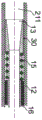
Fig. 11A is a schematic longitudinal cross-sectional view of an adapter in accordance with one embodiment of the present invention wherein the distal coil element of the adapter has been rotated or twisted to reduce the size of the coil prior to insertion into a target catheter or device. Broken line symbols are used to reduce the size of the schematic for clarity.
FIG. 11B is an enlarged detail view of FIG. 11A showing a proximal portion of the adapter.
FIG. 11C is an enlarged detail view of FIG. 11A showing the distal end of the proximal portion of the adapter
FIG. 11D is an enlarged detail view of FIG. 11A showing the distal end of the proximal portion of the adapter and the proximal end of the distal portion of the adapter.
Fig. 12A is a schematic longitudinal cross-sectional view of an adapter and a partial schematic longitudinal cross-sectional view of a distal end of a medical device where a distal coil element of the adapter has been rotated or twisted to reduce the size of the coil prior to insertion of a target medical device and a proximal coil element that has been inserted into the medical device causes the proximal coil element to elongate and reduce in diameter, according to one embodiment of the invention. Broken line symbols are used to reduce the size of the schematic for clarity.
Fig. 12B is an enlarged detail view of fig. 12A showing a proximal portion of the adapter.
Fig. 12C is an enlarged detail view of fig. 12A showing the proximal end of the proximal portion of the adapter, including the proximal coil element.
FIG. 12D is an enlarged detail view of FIG. 12A showing the distal end of the proximal portion of the adapter and the proximal end of the distal portion of the adapter.
Fig. 13A is a schematic longitudinal cross-sectional view of an adapter and a partial schematic longitudinal cross-sectional view of a distal end of a medical device where a distal coil element of the adapter has been rotated or twisted to reduce the size of the coil prior to insertion of the medical device, then released to expand into a lumen of the medical device, and a proximal coil element of the medical device has been inserted causing the proximal coil element to elongate and reduce in diameter, according to one embodiment of the invention. Broken line symbols are used to reduce the size of the schematic for clarity.
Fig. 13B is an enlarged detail view of fig. 13A showing a proximal portion of the adapter.
Fig. 13C is an enlarged detail view of fig. 13A showing the proximal end of the proximal portion of the adapter, including the proximal coil element. .
FIG. 13D is an enlarged detail view of FIG. 13A showing the distal end of the proximal portion of the adapter and the proximal end of the distal portion of the adapter.
FIG. 14A is a schematic longitudinal cross-sectional view of an adapter and a partial schematic longitudinal cross-sectional view of a distal end of a medical device in which a coil element of the adapter has been rotated or twisted to reduce the size of the coil prior to insertion of the medical device and subsequently released to expand into a lumen of the medical device, and a transverse cross-sectional view Z-Z of a distal portion of the adapter, according to one embodiment of the invention. Broken line symbols are used to reduce the size of the schematic for clarity.
FIG. 14B is an enlarged detail view of FIG. 14A showing the proximal end of the distal portion of the adapter.
FIG. 14C is an enlarged detail view of FIG. 14A showing a transverse cross-sectional view Z-Z of the distal end of the distal portion of the adapter and the distal portion of the adapter.
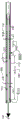
Fig. 15A is a partial schematic longitudinal cross-sectional view of an adapter and a partial schematic longitudinal cross-sectional view of a distal end of a medical device wherein a coil element of the adapter has been rotated or twisted to reduce the size of the coil prior to insertion of the medical device and subsequently released to expand into a lumen of the medical device, and a transverse cross-sectional view Z-Z of the first and second guidewire and adapter distal portions, according to one embodiment of the invention. For clarity, broken line symbols are used to reduce the size of the schematic,
fig. 15B is an enlarged detail view of fig. 15A showing the proximal end of the distal portion of the adapter.
FIG. 15C is an enlarged detail view of FIG. 15A showing a transverse cross-sectional view Z-Z of the distal end of the distal portion of the adapter and the distal portion of the adapter.
Fig. 16A is a partial schematic longitudinal cross-sectional view of an adapter and a partial schematic longitudinal cross-sectional view of a distal end of a medical device wherein a coil element of the adapter has been rotated or twisted to reduce the size of the coil prior to insertion of the medical device and subsequently released to expand into a lumen of the medical device according to one embodiment of the invention, further including transverse cross-sectional views Z-Z of the first and second guidewires and the distal portion of the adapter. For clarity, broken line symbols are used to reduce the size of the schematic,
fig. 16B is an enlarged detail view of fig. 16A showing the proximal end of the distal portion of the adapter.
FIG. 16C is an enlarged detail view of FIG. 16A showing a distal end of the distal portion of the adapter and a transverse cross-sectional view Z-Z of the distal portion of the adapter.
FIG. 17A is a partial schematic longitudinal cross-sectional view of an adapter and a partial schematic longitudinal cross-sectional view of a distal end of a medical device wherein a coil element of the adapter has been rotated or twisted to reduce the size of the coil prior to insertion of a target medical device and subsequently released to expand into a lumen of the medical device, and transverse cross-sectional views Z-Z and Y-Y, according to one embodiment of the invention.
Fig. 17B is an enlarged detail view of fig. 17A showing the proximal end of the distal portion of the adapter.
FIG. 17C is an enlarged detail view of FIG. 17 showing the distal end of the distal portion of the adapter and transverse cross-sectional views Z-Z and Y-Y.
Fig. 18A is a partial schematic longitudinal cross-sectional view of a proximal portion of an adapter according to one embodiment of the present invention. For clarity, broken line symbols are used to reduce the size of the drawing or schematic.
FIG. 18B is a partial schematic longitudinal cross-sectional view of the proximal portion of the adapter shown in FIG. 18A, with the adapter and proximal portion having been inserted into a medical device. For clarity, broken line symbols are used to reduce the size of the drawing or schematic.
FIG. 18C is a partial schematic longitudinal cross-sectional view of the proximal portion of the adapter shown in FIG. 18A, wherein the adapter and proximal portion have been inserted into the target medical device and tension has been transferred to the central tube to axially compress a portion of the coil. For clarity, broken line symbols are used to reduce the size of the drawing or schematic.
FIG. 18D is a partial schematic longitudinal cross-sectional view of the proximal portion of the adapter, where the adapter and proximal portion have been inserted into the target medical device and tension has been transferred to the central tube to axially compress a portion of the coil. For clarity, broken line symbols are used to reduce the size of the drawing or schematic.
FIG. 18E is an enlarged detail view of FIG. 18C showing the compressed portion of the coil.
FIG. 18F is an enlarged detail view of FIG. 18D showing the compressed portion of the coil.
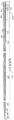
FIG. 19 is a partial schematic longitudinal cross-sectional view of a proximal portion of an adapter according to one embodiment of the invention. For clarity, broken line symbols are used to reduce the size of the drawing or schematic.
Fig. 20A is a partial schematic longitudinal cross-sectional view of a proximal portion of an adapter according to one embodiment of the present invention. For clarity, broken line symbols are used to reduce the size of the drawing or schematic.
Fig. 20B is an enlarged detail view of fig. 20A.
FIG. 21A is a partial schematic longitudinal cross-sectional view of an adapter according to one embodiment of the present invention, wherein the adapter has been inserted into a target medical device. For clarity, broken line symbols are used to reduce the size of the drawing or schematic.
Fig. 21B is an enlarged detail view of fig. 21A.
Detailed Description
Reference will now be made in detail to the preferred embodiments of the present invention, examples of which are illustrated in the accompanying drawings. Wherever possible, the same reference numbers will be used throughout the drawings and the description to refer to the same or like parts.
Fig. 1A, 1B, and 1C illustrate one embodiment of an adapter 10 connected to a distal end 201 of a medical device 200. A suitable medical device 200 is a catheter. The adapter 10 includes a distal portion 20 and a proximal portion 30. The proximal portion 30 is located primarily or entirely within the lumen 211 of the targeted medical device 200. The distal portion 20 of the adapter 10 is primarily external to the targeted medical device 200. The adapter 10 is coaxial with the medical device 200 as shown by longitudinal axis 11. The proximal portion 30 of the adapter 10 includes a coil 12, preferably the coil 12 may be made of nitinol. The coil 12 may be constructed of a wire wound in a general coil shape according to the cross-sectional size.
The coil 12 interfaces with the lumen 211 of the medical device 200 to secure the adapter 10 to the medical device 200. The adapter 10 may be secured into the medical device 200 by interference fit of the coil 12 with the lumen 211. The coil 12 may have an austenite finish temperature (Af) that is less than body temperature, such as an average 37 ℃ of normal body temperature, and greater than a temperature typically expected in an operating room or catheter laboratory, such as about 25 ℃ to 30 ℃. Coil 12 may be twisted and/or elongated to reduce the size or diameter of coil 12 such that coil 12d has a smaller size or diameter than lumen 211 to facilitate placement of adapter 10 inside medical device 200. When the adapter 10 is heated to body temperature during in vivo use, the coil 12 may expand to provide additional securement force to the medical device 200.
Alternatively, the coil 12 may be designed to have a smaller size or diameter than the lumen 211 of the medical device 200 in an operating room environment by physical restriction or restraint, and once the adapter 10 is placed in the medical device 200 and the physical restraint is removed, the coil 12 may expand to connect with the target catheter or the lumen 211 of the medical device 200. The coil 12 is shown as having a constant circular cross-section, or the coil 12 may have a rectangular cross-section of a pancake coil design. The flat coil design benefits from a smaller volume of the coil 12, yet still gives adequate retention by interference fit with the inner cavity 211. The cross-section is variable as the length of the coil 12 is expanded. The variable cross-section coil 12 design provides the advantage of biased securement toward either end of the adapter 10. The coil 12 may have a variable flexibility and bend around the longitudinal axis 11.
In one embodiment, the coil 12 may additionally reinforce the medical device 200 to improve kink resistance. The adapter 10 includes a tube 16 coupled to a distal portion 20 of the adapter 10 and is coaxially interfaced with the coil 12. Tube 16 is provided with a funnel portion 13 at the proximal end 30 of adapter 10. The funnel portion 13 may assist in threading a guidewire from the proximal end (not shown) of the medical device 200 to the distal portion 20 of the adapter 10. The tube 16 is preferably a polymeric tube and may include a braid or other reinforcement. The coil 12 includes a proximal end 15 coupled, bonded or otherwise attached to a proximal end 19 of a tube 16. The proximal end 15 of the coil 12 may remain smaller than the size of the lumen 211 to facilitate loading of the adapter 10 into the medical device 200 during use. The distal end 14 of the coil 12 may remain smaller than the size of the lumen 211. For example, proximal end 15 or distal end 14 may be heat set or formed to a size smaller than the size of lumen 211.
The distal end 14 provides a location for the coil 12 to grasp or hold in order to twist and/or stretch the coil 12 to a reduced size to facilitate positioning the adapter 10 within the medical device 200. The distal portion 20 of the adaptor 10 is preferably made of a thermoplastic elastomer. Examples of thermoplastic elastomers or soft polymers include polyether urethanes and polyether block amides, such as-40 DPEBAX manufactured by Arkema.
In this embodiment, the distal portion 20 is designed such that a medical device 200 having a single guidewire channel can be modified to have two guidewire channels. The distal portion 20 includes a first lumen 21 and a second lumen 22 for a first guidewire. The second lumen 22 is connected to the lumen 211 of the medical device 200 by the tube 16 of the adapter 10. This allows greater flexibility for the user, such as replacing a guidewire, or administering a contrast or drug through the target catheter or device lumen 211. The path of the first guidewire is shown by a first lumen centerline 23 and the path of the second guidewire is shown by a second lumen centerline 24. It can be seen from this that the path of the lumen centerline 23 is external to the medical device 200.
The distal portion 20 includes a reduced-size portion 17 at the proximal end 26 of the distal portion 20 that interfaces with the lumen 211 of the medical device 200 by selection of materials (e.g., thermoplastic elastomers or soft polymers) and geometric design. The slight interference fit between the reduced size portion 17 and the lumen 211 provides a stable structure during introduction of the adapter 10 and medical device 200 into a body cavity or vessel. The adapter 10 may include a tapered distal end 27 of the distal portion 20, the tapered distal end 27 facilitating passage of a medical device 200 coupled to the adapter 10 within a body lumen.
Fig. 2 shows the structure of the adapter 10, wherein the coil 12 is reduced to a smaller size by stretching. Fig. 3 shows the structure of the adapter 10, wherein the coil 12 is reduced to a smaller size by rotation or twisting. An alternative embodiment of the adapter 10 is that the coil 12 is reduced in size by a twist and stretch fit so that the adapter 10 can be attached into the medical device 200. The distance Ds2 between the distal end 14 of the coil 12 and the proximal end 26 of the distal portion 20 shown in FIGS. 2 and 3 is less than the distance Ds1 between the distal end 14 of the coil 12 and the proximal end 26 of the distal portion 20 shown in FIG. 1C. In an alternative embodiment of the adapter 10, if the user twists and/or stretches the coil 12 such that the distal end 14 of the coil 12 is a distance from the proximal end 26 of the distal portion 20, the user will know that the adapter 10 has been safely inserted into the medical device 200. For example, the tube 16 may be marked to indicate the proper location of the distal end 14 of the coil 12.
Fig. 4 shows an alternative embodiment of the invention, an adapter 40. The adapter 40 has a distal portion 41 and a proximal portion 42, which are similar to the distal portion 20 and the proximal portion 30 of the adapter 10 shown in fig. 1A, 1B, and 1C. The adapter 40 includes a tube 16 having a funnel portion 13 located at a proximal portion 42 of the adapter 40. Tube 16 is attached to distal portion 41. The coil 12 is also connected to the distal portion 41 and to the lumen 211 of the medical device 200 in a manner that secures the adapter 40 to the medical device 200. The connection may be accomplished in a similar manner as previously described for adapter 10.
Fig. 5 shows an alternative embodiment of the invention, an adapter 50. The adapter 50 has a distal portion 51 and a proximal portion 52 that are similar to the distal portion 20 and the proximal portion 30 of the adapter 10 shown in fig. 1A, 1B, and 1C. Adapter 50 is similar to adapter 40 except that portion 53 of coil 12 that engages lumen 211 has a greater pitch than the corresponding portion of adapter 40. For example, the pitch may be in the range of about 2 to 10 times the cross-sectional dimension of the coil 12. The adapter 50 also includes a proximal end 25 of the coil 12, the proximal end 25 of the coil 12 being similar in use and form to the distal end 14 of the adapter 10, except that the coil 12 is stretched or twisted toward the proximal portion 52 of the adapter 50 to make the coil 12 smaller in size to facilitate insertion of the adapter 50 into the medical device 200.
Fig. 6 shows an alternative embodiment of the invention, an adapter 60. The adapter 60 has a distal portion 61 and a proximal portion 62 that are similar to the distal portion 20 and the proximal portion 30 of the adapter 10 shown in fig. 1A, 1B, and 1C, and that otherwise function similarly. The proximal portion 62 includes the coil 12, the coil 12 having a reduced size portion 18 such that it can grip the tube 16. The coil 12 may be heat set or otherwise formed to interface with the lumen 211 of the medical device 200. The inner diameter dia1 of the reduced size section 18 is smaller than the outer diameter dia2 of the tube 16 to contact and grip the tube 16 during use. The reduced diameter portion 18 of the coil 12 may be glued, and reflowed thermally to the tube 16 to further couple the coil 12 to the proximal portion 62.
Fig. 7 shows the construction of the adapter 70 in which the coil 12 has been reduced to a smaller size by stretching and/or twisting, similar to that shown in fig. 2 and 3. The adapter 70 has a distal portion 71 and a proximal portion 72 that are similar to the distal portion 20 and the proximal portion 30 of the adapter 10 shown in fig. 1A, 1B, and 1C. The distal portion 71 includes a single lumen tip 73 coaxial with the longitudinal axis 11. The single lumen tip 73 has been reinforced by a reinforcing portion 74. For example, the reinforcing portion 74 may be a coil or a braid. The reinforcing portion 74 includes a proximal coil portion 75 extending past the proximal end of the single lumen tip 73. The proximal coil portion 75 provides a slight interference fit with the lumen 211 and provides a stable connection during initial insertion of the adapter 70 into the medical device 200 by the user. The reinforcing portion 74 reinforces the distal portion 71 and may facilitate passage through the medical device 200 through tight lesions.
FIG. 8A, FIG. 8B,Fig. 8C, 8D, 8E and 8F illustrate an alternative embodiment of the present invention, namely an adapter 100. The adapter 100 has a distal portion 170 and a proximal portion 110. The proximal portion 110 includes a coil 130. The coil 130 is wound with a wire 136 and has multiple diameters along its length. In one embodiment, wire 136 is flat, having a rectangular or square cross-section. For example, the coil 130 may have a diameter of The winding length a 131. The
 wire 136 is at the wound length a131 segment, its winding pitch is variable, not constant, and the pitch is varied from about twice the width 162 of the flat wire 136 at the proximal end of the wound length a131 to about the width of the flat wire 136, such that the wire 136 is tightly wound at the distal end of the wound length a 131. An advantage of a variable pitch winding length is that more widely spaced pitch coils can be more flexible, while closely wound coils are stiffer and stronger by twisting or bending. Variable pitch winding lengths also have the advantage that more widely spaced pitch coils can also provide better bonding geometry so that adhesive can flow between the windings of the coil 130. When the wire 136 is wound distally to form the coil 130, the diameter of the coil 130 at the length transition 132 is sized from Transformation into
 size Wire
Wire 136 is of diameter at length B133 And (6) winding. The winding pitch of
 wire 136 is variable, not constant, over winding length B133, and changes from a pitch approximately equal to the width 162 of wire 136, i.e., a pitch that causes wire 136 to be tightly wound, to a significantly larger pitch, i.e., a pitch that is approximately 5 times the tight winding pitch. From close winding to more than 5 times the width 162 of the flat wire 136, this sharp or rapid pitch change isAdvantageously, as the coil 130 is constrained within the lumen 211 of the medical device 200 during use, it creates a wedge shape and may improve the interference fit and binding of the adapter 100 within the medical device 200. Typically, the amount of the liquid to be used, will be smaller in size than the
 lumen 211 of the targeted medical device 200, and will be larger in size than the
 lumen 211 of the medical device 200. As the wire 136 is wound distally to form the coil 130, the diameter of the coil 130 is sized from the length transition 134 Transition to smaller size
 The winding pitch of the
 wire 136 is nearly uniform at the winding length transition section 134.
In an alternative embodiment, the wire 136 is at the winding length transition 134 with a variable winding pitch. The wire 136 is wound distally from the length transition section 134 to continue to be dimensioned to be at a winding length D135 The
The coil 130. Typically, the amount of the liquid to be used, will be smaller in size than the
 lumen 211 of the medical device 200. Diameter of Is located within the
 cavities 178 and 177 of the distal portion 170 of the adapter 100. Lumen 177 is sized to interface with the distal end of medical device 200, while lumen 178 is sized to receive a diameter The
The cavity 178 is sized to allow the winding length D135 of the coil 130 to move freely within the cavity 178 without an external mechanism to grip, pinch, or otherwise secure the proximal end of the distal portion 170 in the region of the cavity 178. When there is an external mechanism to grip, squeeze or secure the proximal end of the distal portion 170 in the region of the cavity 178, the cavity 178 is sized to prevent rotation or movement of a portion of the coil 130 over the winding length D135, securing the coil 130, the coil 130 having previously been rotated/twisted to a smaller dimension to facilitate insertion of the proximal portion 110 of the adapter 100 into the medical device 200.
The coil 130 may be made of nitinol and have an austenite finish temperature (Af) that is about equal to or less than the ambient temperature of the operating room or catheter lab environment, whereupon the coil 130 releases from the smaller-sized state and expands upon insertion of the medical device 200. Alternatively, the coil 130 may be made of nitinol and have an austenite finish temperature (Af) that is less than body temperature, but greater than a temperature typically expected in an operating room or catheter lab, such as about 25 ℃ to 30 ℃, except that in region T161, the coil 130 has been selectively heat treated to an austenite finish temperature (Af) that is about equal to or less than an ambient temperature of the operating room or catheter lab environment (e.g., about less than 18 ℃) in T161, such that the region T161 of the nitinol coil 130 is released and expanded from a smaller size state upon insertion of the medical device 200 in the catheter lab environment. The coil 130 having multi-zone or heat-variable properties has the following advantages: the adapter 100 can be easily inserted into the medical device 200 with some of the coils 130 having a higher Af temperature. The selectively heat treated portion of the coil 130 in the region T161 is biased to engage the interior lumen 211 of the medical device 200 more than the remainder of the coil 130 to facilitate forming a wedge and being confined within the interior lumen 211 of the medical device 200 after the coil 130 is released from the smaller size state as described above. The region T161 of the coil 130 provides additional fixation and structure for the adapter 100 when the adapter 100 is warmed up to body temperature during in vivo use. As shown, the region T161 includes a portion of length a131, a transition segment 132, and a portion of length B133. Alternatively, the region T161 may include only a portion of the transition segment 132 and a portion of the length B133 or other combinations.

A central tube 182 connects the proximal and distal ends 120 of the coil 130 in the region of the length a131 to the distal portion 170. The distal portion 170 of the adapter 100 has an outer body 179 that is generally cylindrical or rotationally shaped. Alternatively, the outer body may partially or fully have a non-rotating profile. The outer body 179 can be made of a polymer. The outer body may be reinforced with metal, polymer or ceramic fibers, filaments, laser cut hypotubes, and the like. The outer body 179 can be a laminate structure that can include a plurality of tube elements or materials. The outer body 179 can have a stepped, tapered shape with a first outer diameter 185 and a second outer diameter 184 connected by a tapered portion. Distal portion 170 has a first outlet lumen 186 of central lumen 183 and a second outlet lumen 187 of central lumen 183, which are opposite each other in outer body 179. The first outlet lumen 186 emanates from the central axis of the central lumen 183 at an angle a1 toward the proximal portion 110 of the adapter 100. The angle along the direction of angle a1 is advantageous as the guidewire passes from the distal tip 181 of the distal portion 170, through the central lumen 183, and out the first exit lumen 186. The second outlet lumen 187 is oriented from the central axis of the central lumen 183 at an angle a2 toward the distal end of the adapter 100. The angle along the direction of angle a2 is advantageous as the guidewire passes from the proximal end 120 of the proximal portion 110, through the central lumen 183, and out the second exit lumen 187. Central tube 182 terminates proximal to distal tip 181 such that a portion of central lumen 183 is made up of only outer body 179. Alternatively, the central tube 182 may extend to the distal tip 181 or terminate at a closer location within the outer body 179. Where necessary, the center tube 182 may form a majority of the length of the distal end portion 170 into the central lumen 183, for example, if the center tube 182 is a braided or wire reinforced structure.
In one embodiment, the coil 130 has been rotated or twisted about the longitudinal axis of the coil 130 and the center tube 182, while the center tube 182 and the center tube 182 connected thereto A portion of the winding length a131 is captively secured to reduce its size, particularly at
 transition 132, length B133, and transition 134. After the coil 130 has been rotated or twisted to reduce the size of the transition segment 132, length B133, and transition segment 134, a portion of the distal end 198 of the coil 130 has been at a smaller diameter, which may be crimped and fixed relative to the distal portion 70 and the coupled central tube 182 such that the coil 130 is crimped at the reduced diameter. When a portion of the distal end 198 of the coil 130, i.e., the constrained length D135, is released, the coil 130 will expand from the undersized state back to its unconstrained size state, and such expansion will tend to occur beginning at the length D135 of the unattached distal end 197, with the coil 130 deploying/unwinding from the distal end and gradually proximally. In one embodiment, the coil 130 is progressively unwound/unwound from the distal end 197 of the coil 130 toward the proximal end, the distal element of the coil 130 substantially not inhibiting expansion and engagement of portions of the transition segment 132 and length B133 into the lumen 211 of the medical device 200, facilitating the formation of the wedge shape.
Fig. 9A, 9B, 9C, 9D, 9E, 9G and 9H illustrate an alternative embodiment of the present invention, an adapter 101. Adapter 101 is similar to adapter 100Having a distal portion 171 and a proximal portion 111. Proximal portion 111 includes a coil 140 similar to coil 130. The coil 140 is wound from wire 136 and has multiple diameters as the length of the coil 140 is unwound. As shown, coil 140 has a diameter of The winding length a 141. The
 wire 136 is at a winding length a141 segment whose winding pitch is variable, not constant, and the pitch is varied from about twice the width 162 of the flat wire 136 at the proximal end of the winding length a141 to about the width of the flat wire 136 such that the wire 136 is tightly wound at the distal end of the winding length a 141. An advantage of a variable pitch winding length is that more widely spaced pitch coils can be more flexible, while closely wound coils are stiffer and stronger by twisting or bending. Variable pitch winding lengths also have the advantage that more widely spaced pitch coils can also provide better bonding geometry so that adhesive can flow between windings of the coil 140. When the wire 136 is wound distally to form the coil 140, the diameter of the coil 140 at the length transition 160 is sized from Transformation into
 size Wire
Wire 136 is of diameter at length B133 And (6) winding. The winding pitch of
 wire 136, at winding length B133, is variable, not constant, and varies from a pitch approximately equal to the width 162 of wire 136, i.e., a pitch that causes wire 136 to be tightly wound, to a significantly larger pitch, i.e., a pitch that is approximately 5 times the width 162 of flat wire 136. This abrupt or rapid change in pitch, from being tightly wound to more than 5 times the width 162 of the flat wire 136, is advantageous because when the coil 140 is constrained within the lumen 211 of the medical device 200 during use, it creates a wedge shape and may improve the fit of the adapter 101 within a catheter or other deviceInterference fit and binding within the medical device 200. Typically, the amount of the liquid to be used, will be smaller in size than the
 lumen 211 of the medical device 200, and will be larger in size than the
 lumen 211 of the medical device 200. As the wire 136 is wound distally to form the coil 140, the diameter of the coil 140 is sized at a length transition 142 Transition to smaller size
 The
The wire 136 has a substantially uniform winding pitch at a winding length transition 142. Alternatively, the wire 136 is at a winding length transition 142, the winding pitch of which is variable. The wire 136 continues to be wound distally from the length transition section 142 to be sized at the wound length C143 The
The coil 140. May be similar or slightly smaller in size than the
 lumen 211 of the medical device 200 such that the coil 140 is unbound from the small-sized state to secure the adapter 101 to the lumen 211 during use. Has a size of The winding length C143 of the
 coil 140 of substantially no inhibition dimension The winding length B133 of the
 coil 140 engages and secures the coil 140 to the lumen 211 of the medical device 200. When the wire 136 is wound distally to form the coil 140, the diameter of the coil 140 is sized at the length transition 146 To a smaller size
 The winding pitch of the
 wire 136 is substantially uniform at the winding length transition 146. Alternatively, the wire 136 is at a winding length transition 146, the winding pitch of which is variable. The wire 136 continues to be wound distally from the length transition section 146 to be sized to be at winding length D145 The
The coil 140. Typically, the amount of the liquid to be used, will be smaller in size than the
 lumen 211 of the medical device 200. Has a size of Is located within
 cavities 178 and 177 at proximal end 199 of distal portion 171 of adapter 101. The cavity 177 is sized to interface with a distal end (not shown) of the medical device 200, and the cavity 178 is sized to receive a lumen sized to The
The coil 140.
The cavity 178 is sized to allow the winding length D145 of the coil 140 to move freely within the cavity 178 without an external mechanism to grip, pinch, or otherwise secure the proximal end 199 of the distal portion 171 in the region of the cavity 178. When there is an external mechanism to grip, compress, or otherwise secure the proximal end 199 of the distal portion 170 in the region of the cavity 178, the cavity 178 is sized to prevent rotation or movement of a portion of the coil 140 at the winding length D145, securing the coil 140, which coil 140 was previously rotated/twisted to a smaller dimension to facilitate insertion of the proximal portion 110 of the adapter 101 into the medical device 200.
The coil 140 has a diameter of Is partially or fully coupled, bonded, or otherwise attached to the
 second tube element 190 at the winding length a141, forming a portion of the second lumen 191 of the adapter 101. The wrapping length 141 is attached to the second tube element 190 primarily near the transition segment 160, which may be advantageous in that the uncoupled portion of the wrapping length 141 may be extended proximally to add more structure and support to the adapter 101 and medical device 200. The proximal end 120 of the adapter 101 is attached to the second tube element 190 in a manner similar to the attachment of the proximal end 120 of the adapter 100 to the center tube 182.
Fig. 10A, 10B, 10C, 10D, 10E, 10F and 10G illustrate an alternative embodiment of the present invention, namely an adapter 102. The adapter 102 is similar to the adapter 100, having a distal portion 172 and a proximal portion 112. The proximal portion 112 includes an and distanceA coil 130 closer to the distal portion 172 and a coil 147 closer to the proximal end 123. Coil 130 is a left-handed helix and coil 147 is a right-handed helix. The coil 130 is depicted as part of the adapter 100. Coil 147 is similar to coil 130. The coil 147 is wound from wire 153 and has multiple diameters over the length of the coil 147. Wire 153 may be a flat wire. As shown, coil 147 has a diameter at the proximal end of
 The winding length E148.
When the wire 153 is wound distally to form the coil 147, the diameter of the coil 147 is sized from the length transition 149 Conversion to
 larger size Wire
Wire 153 by diameter Wound for a certain length F150. The winding pitch of the
 wire 153 is variable, not constant, over a winding length F150, and the pitch is changed from about equal to the width of the wire 153, i.e., the pitch at which the wire 153 is tightly wound, to a significantly larger pitch, i.e., about 5 times the width of the wire 153. This abrupt or rapid change in pitch is advantageous from a tight winding to more than 5 times the width of the wire 153 because when the coil 147 is constrained within the lumen 211 of the medical device 200 during use, it creates a wedge shape and can improve the interference fit and binding of the adapter 102 within the medical device 200. Typically, the amount of the liquid to be used, will be smaller in size than the
 lumen 211 of the medical device 200, and will be larger in size than the
 lumen 211 of the medical device 200.
The adapter 102 includes coaxial pipe elements, a center tube 192 and a reinforced tube member 194. The center tube 192 forms a portion of the central lumen 193 of the adapter 102. The proximal end 123 of the adapter 102 is attached or coupled to the center tube 192. The proximal end 123 is comprised of a funnel element 124. The center tube 192 and the funnel element 124 may be integral such that the funnel element 124 becomes a flared end of the center tube 192. An advantage of the funnel element 124 is that it facilitates backloading of the guidewire through the medical device 200 and the adapter 100 during use. Both the center tube 192 and the reinforcing tube member 194 are attached, bonded or coupled to the distal portion 172 of the adapter 102. As shown, the stiffening tube member 194 terminates adjacent the central tube 192, and the central tube 192 terminates adjacent the distal end 181 of the proximal portion 172 of the adapter 102. Alternative embodiments or configurations may have a reinforced tube member 194 connected to the distal portion 172 and a center tube 192 connected to the reinforced tube member 194 to form the adapter 102. This embodiment has the following advantages: features that optimize tip performance may be achieved if the stiffening tube member 194 terminates closer to the distal tip 181, such as a cross-bracing device, while the central tube 192 primarily provides a more optimized central lumen 193, such as for a guidewire. In this embodiment, the reinforced tube member 194 and the center tube 192 may terminate together, or the center tube 192 may terminate closer to some extent than the reinforced tube member 194.
All or a portion of the length E148 of the coil 147 will be attached, bonded or otherwise coupled to the stiffening tube member 194. This may be accomplished by attaching a portion of the length E148 segment to the reinforced tube member 194 using an adhesive. In a similar manner as previously described, a portion or all of the length A131 of coil 130 is bonded or attached to the stiffening tube member 194.
The coil 130 has a size of The inner diameter of the segments is typically greater than the outer diameter of the
 second pipe element 190 or the central pipe 182 or the reinforced pipe member 194.
11A, 11B, 11C, and 11D show an adapter 102 in which a coil 130 has been rotated or twisted, wrapped or wound in some manner to a smaller diameter The
The coil 130 has been rotated or twisted to wind the length at the combination of the transition section 132 and length B154 such that the transition section 132, the wound length B133, and the transition section 134 remain at the smaller diameter The state of (1). Diameter of
 About equal to or smaller than the
 lumen 211 of the medical device 200 to facilitate insertion of the adapter 102. A temporary restraint 195 is located on the portion of the coil 130 to secure the coil 130 at the smaller diameter To (3). The
 temporary restraint 195 facilitates keeping the coil 130 at a smaller diameter Without moving the length D135 section of the
 coil 130. The length D135 is not attached or coupled to the stiffening tube member 194.
11A, 11B, 11C and 11D show a clamping element 196 that will clamp or secure a portion of length D135 against rotation so that temporary restraint 195 may be removed and coil 130 will remain stationary, including maintaining a smaller diameter It may be advantageous to include a
 temporary restraint 195, only the temporary restraint 195 limiting the coil 130 to a smaller diameter To be placed in an adapter enclosure for convenient termination at the customer siteEnd sterilization and/or shipping, transport and storage, which will greatly reduce the reaction time required for loading of the attached portion of
 coil 130 at length a 131. When the adapter is ready for use in an operating room or catheter lab, the clamping element 196 may be used and the temporary restraint element 195 removed to allow the adapter to be inserted into the medical device 200.
Fig. 12A, 12B, 12C, and 12D illustrate the adapter 102, the adapter 102 having been initially inserted into the medical device 200 while the coil 130 has been rotated or wound to a smaller diameter And is held in this position by the clamping element. The
 coil 147 is shown after being inserted into the lumen 211 of the medical device 200. When the coil 147 is inserted, as shown in FIGS. 11A, 11B, 11C, and 11D at length F150 and transition 149, it conforms to the size of the lumen 211 of the medical device 200 and is stretched and/or rotated to a smaller diameter "159. Similar to that previously described, transitioning from a tightly wound pitch to 5 times the tightly wound pitch, i.e., about 5 times the width of the
 wire 153, this sharp or rapid increase in pitch is advantageous as shown because when the coil 147 is constrained within the lumen 211 of the medical device 200 during use, it creates a wedge shape having an angle A127 that is greater than or equal to 15 degrees and improves the interference fit and binding of the adapter 100 within the medical device 200. In the embodiment of adapter 102, coil 147 is a guide coil inserted into lumen 211 of medical device 200. When the coil 147 is inserted into the lumen 211, the loop of wire 153, which is about equal in size to the lumen 211 within the transition 149 and length F150, meets the wall 212 of the lumen 211 and is reduced in size by stretching and rotating (primarily stretching) so that the transition and length F158 are longer than the combination of the transition 149 and length F150, and the entire coil 147 can be inserted into the medical device 200. This mode of action differs from that of coil 130.
As shown in fig. 13A, 13B, 13C and 13D, after the adapter 102 is inserted into the subject device or catheter 200 and the clamping element 196 is removed, the coil 130 will rotate and expand to the lumen size to wrap a length in combination including a portion of the transition segment 132, the length B133 and the length B156 of the transition segment 134, connecting with the wall 212 of the lumen 211. The coil 130 is designed to transition from a tightly wound pitch to 5 times the tightly wound pitch, i.e., about 5 times the width of the wire 136, within the geometry of the coil 130 after expanding to conform to the dimensions of the lumen 211, this sharp or rapid increase producing a wedge shape having an angle B163 that is about 15 degrees or greater. The advantage of the mode of action of the coil 130 over the mode of action of the coil 147 is that by primarily rotating the coil 130 to conform to the size of the lumen 211, rather than primarily stretching the coil 147 to conform to the size of the lumen 211, it is less likely that axial rewinding will be required when the coil 130 is allowed to expand, and its insertion into the adapter force can be removed. When the adapter 102 is inserted into the medical device 200 through the adhesive connection of length a131 to form the reinforced tube member 194, the coil 147 may be pulled into the lumen 211 of the medical device 200. After the adapter 102 has been inserted into the medical device 200, the coil 147 will be axially rewound toward the distal end of the adapter 102, while the coil 130 can be rotated into place without external pulling force. It may be advantageous to include two modes of action in one adapter in order to provide redundancy when one mode of holding the adapter 102 in the medical device 200 is less efficient than the other mode. Alternatively, the coils 130 and 147 are wound in opposite directions so that if the adapter 102 is placed under an external torsional load, the adapter 102 can function optimally in either direction of the external torsional load.
Fig. 14A, 14B, and 14C show adapter 103 having been inserted into medical device 200 and coil 130 having been deployed in connection with lumen 211 to secure adapter 103. The adaptor 103 includes a distal portion 173 and a proximal portion 113, wherein the proximal portion 113 is very similar to the proximal portions 110 and 111 described previously. The distal portion 173 of the adaptor 103 has an outer body 179 that is generally cylindrical or rotationally shaped. Alternatively, the distal portion 173 of the adaptor 103 may have a non-rotating profile, partially or entirely. The outer body 179 has a stepped, tapered shape with a first outer profile 185, a second outer profile 184, and a third outer profile 180 connected by a tapered portion. The distal portion 173 has a first tube element 188, which constitutes a first lumen 189. The first tube member 188 terminates adjacent the distal tip 181 such that a portion of the first lumen 189 is formed solely by the outer body 179. First tube element 188 may extend to distal tip 181 or terminate at a more proximal location within outer body 179. A second tube element 190 forming part of a second lumen 191 connects the coil element 130 of the proximal portion 113 to the distal portion 173. The second lumen 191 and the first lumen 189 exit the outer body 179 in a similar manner as the second outlet lumen 187 and the first outlet lumen. As shown, the second and first tube elements 190, 188 do not extend completely to the edge 230 of the outer body 179 of the distal portion 173, with a portion of the second and first tube elements 190, 188 terminating before the edge 230 of the outer body 179, such that the outer body 179 of the distal portion 173 constitutes a portion of the second lumen 191 and the first lumen 189. A third outer profile 180 of the outer body 179 includes the first cavity 166 and the second cavity 169 as shown in longitudinal and transverse cross-sectional views Z-Z. The first cavity 166 and the second cavity 169 are shown as open cavities. Alternatively, the first and second cavities 166, 169 may be closed cavities, such as circular cavities. As shown, the first cavity 166 and the second cavity 169 are held 180 degrees opposite each other. Alternatively, the first cavity 166 and the second cavity 169 may have selectable orientations.
Fig. 15A, 15B, and 15C illustrate the adapter 103 shown in fig. 14A, 14B, and 14C with the addition of a first cord 167 and a second cord 168. Preferably, the first thread 167 begins at a first end (not shown) located outside the patient's body and extends distally through the outside of the medical device 200, then through the first lumen 166 and the first lumen 189, exiting from the distal end 181 of the distal portion 173 and extending to the second end 231 of the first thread 167. Preferably, the second wire 168 begins at a first end (not shown) located outside the patient's body and extends distally through a proximal end (not shown) of the medical device 200, then continues within the lumen 211 of the medical device 200 through the second lumen 191, then wraps proximally back into the second lumen 169, then continues proximally along the outside of the medical device and extends to a second end (not shown) of the second wire 168. A second end (not shown) of the second cord 168 may terminate outside the patient. The adapter 103 may be advantageous when the medical device 200 is used as a balloon in percutaneous transluminal balloon angioplasty. The first wire 167 can serve as a guidewire to guide the medical device 200, which is a balloon for percutaneous transluminal balloon angioplasty, to the site of an arterial lesion or occlusion and provide a mechanism to direct stress concentrations into the walls of the artery and lesion to preferentially cut or destroy the lesion, thereby improving the ability of the balloon to expand at the target lesion. The second end of the second wire 168 may extend proximally beyond the balloon of the medical device 200 such that the second wire 168 also provides a mechanism capable of inducing a stress concentration similar to the first wire 167. The second line 168 may have a curve 164. For example, the second wire 168 may be made of nitinol and heat treated to form the shape of the curve 164. Alternatively, the second wire 168 may be designed to easily form the bend 164. For example, the second wire 168 may be made of nitinol and heat treated to have an austenite finish temperature that allows the second wire 168 to easily bend into the curve 164 and retain that shape during use, e.g., the austenite finish temperature may exceed body temperature (37 ℃). The second wire 168 may be placed in the adapter 103 and medical device 200 of the balloon prior to introducing the adapter 103 and medical device 200 into the patient. After the inflation process is complete, the second wire 168 may be withdrawn from the proximal end (not shown) of the medical device 200. Alternatively, the second wire 168 is guided through the medical device 200 and positioned within the body.
Fig. 16A, 16B, and 16C show an adapter 104 similar to adapter 103. The adapter 104 comprises a distal portion 174, said distal portion 174 comprising the third outer contour 126 of the outer body 179. The second cord 125 includes a first end 232, the first end 232 being attached to the outer body 179 at a top or edge 233 of the third outer profile 126. The second wire 125 extends proximally along the exterior of the medical device 200 from the outer body 179 and the distal portion 174 and to a second end (not shown) of the second wire 125. The second end (not shown) of the second wire 125 may terminate in an artery or body vessel, terminating in a loop or fold, thereby minimizing vessel trauma or extending proximally all the way out of the patient's body. As shown in the transverse cross-sectional view Z-Z of the third outer profile 126, the third outer profile 126 has no cavity for the first thread 167. The first thread 167 may alternatively extend distally along the third outer contour 126.
The first outer contour 185, the second outer contour 184 and the third outer contour 126 generally increase in size in order from the first outer contour 185 to the third outer contour 126. However, the third outer profile 126 has a reduced dimension portion 165 that is approximately equal in size to the second outer profile 184. This may be advantageous because it allows space for the second wire 125 to fold and extend distally when the medical device 200 and adapter 104 are withdrawn from the artery and patient.
Fig. 17A, 17B, and 17C show an adapter 105 similar to adapter 101. The adapter 105 includes a distal portion 175. Distal portion 175 has an outer body 179 typically made of a soft or elastomeric polymer. The distal portion 175 incorporates a first tube element 188, the first tube element 188 forming a portion of a first lumen 189 in the outer body 179. First lumen 189 exits outer body 179 distally at distal tip 181. The first inner cavity 189 is partially defined by the first tube member 188 and the outer body 179. The first lumen 189 exits the outer body 179 proximally at an outlet 253, which outlet 253 is proximal to a distal outlet 254 from a second lumen 191 of the outer body 179. The second lumen 191 is partially formed by the second tube element 190 and the outer body 179. As shown in section Y-Y, the second lumen 191 transitions from the closed portion as it exits the outer body 179. First and second pipe elements 188, 190 are side-by-side overlapping within outer body 179 over length 251. The first lumen 189 and the second lumen 191 overlap by a length 255. An alternative embodiment of distal portion 175 includes a first lumen 189 formed entirely of outer body 179 without first tube member 188.
The distal portion 179 also includes an aperture or passage 252 proximate the distal end 234 of the cavity 178 for accessing the cavity 178. The holes 252 facilitate the venting of air out of the cavity 178 prior to use. The holes 252 may also provide additional conduits to deliver fluid or contrast through the lumen 211 of the medical device 200.
Fig. 18A, 18B, 18C, 18D, 18E and 18F illustrate an alternative embodiment of the coil 257 of the proximal portion 113 of the adapter 105 of the present invention. The coils 257 have variable diameters and pitches. Similar to other coil embodiments, coil 257 has a proximal diameter
 And has a larger diameter at the
 distal end 270 of the coil 257 Diameter of
 coil 257 Gradually transits to
 The
The coil 257 is coupled or otherwise attached to the center tube 263, forming a center lumen 271, similar to the case of the center tube 182 at length G258. The uncoupled distal portion length H1272 of coil 257 comprises a diameter of Has a diameter of
 And a section with a diameter that transitions between the two diameters. The uncoupled distal portion length H1272 segment of the
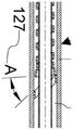
 coil 257 is shown as having a variable pitch that is not tightly wound, but may include a tightly wound pitch. The uncoupled distal portion 272 has a smaller diameterHaving a tight winding pitch followed by a gradual transition to a larger diameter may be advantageous because the central tube 263 may have less axial movement under axial load after the adapter 105 is attached to the target medical device 200. Fig. 18B shows the coil 257 of the proximal portion 113 of the adapter 105 after the adapter 105 is inserted and positioned into the medical device 200 having the lumen 211 as previously described. When the coil 257 is inserted, the uncoupled distal portion extends to a length H2259 such that a portion of the coil 257 forms an angle a127 as previously described. Proximal portion 113 also includes a proximal end 120 and is comprised of an inner member 122 forming a funnel and an outer member 256. Outer member 256, similar to outer member 121, may be radiopaque or partially radiopaque to provide a landmark for the proximal end of the adapter, but is shorter and does not completely cover inner member 122, having a shorter longitudinal length than inner member 122.
Fig. 18C shows an embodiment of the proximal portion 113 and coil 257 such that, after it is inserted and positioned into the target device 200 as previously described, and with the centertube 263 placed under the axial load F261, the uncoupled distal portion length H3260 of the coil 257 becomes shorter than the length H2259 before the axial load F261 is applied. Alternatively, a portion of the uncoupled coil windings forming uncoupled distal portion length H2 are compressed together axially under axial load F261 and contact each other, effectively forming a wedge at angle a127, as shown in enlarged detail fig. 18E.
Fig. 18D shows yet another embodiment of the proximal portion 113 and coil 257 such that, after it is inserted and positioned into the subject device 200 as previously described, and with the central tube 263 placed under the axial load F261, the uncoupled distal portion length H4262 of the coil 257 becomes shorter than the length H2259 before the axial load F261 is applied. Alternatively, a portion of the uncoupled coil windings forming uncoupled distal portion length H2259 are compressed together axially under axial load F261 and contact each other, and nest together or invaginate, effectively forming a wedge at angle a127, as shown in enlarged detail fig. 18F. Nested coil winding as shown in fig. 18D and 18F may be advantageous because it may increase the securement of the adapter.
It is contemplated that multiple coils similar to coil 257 may be coupled in series to central tube 263 to create proximal portion 113. The proximal portion 113 of this design may increase the robustness of the adapter to secure to the medical device 200. A multi-coil configuration of this nature may include left and right handed coils as previously described, which may minimize offset or potential fixation issues when the central tube 263 is under torsional load.
Fig. 19 shows one embodiment of the proximal portion 114 of the adapter, which includes a coil 264 similar to coil 257. The coil 264 includes all of the elements of the coil 257, plus an uncoupled length J265, the uncoupled length J265 extending from the larger diameter Transition to a smaller diameter that is preferably smaller than the diameter of the
 lumen 211 of the medical device 200, which is equivalent to the diameter Similarly. A coil design of this nature may be advantageous because it allows the
 proximal portion 114 to be removed from the medical device 200. The user may grasp a coil wrap of length J265 and pull and/or rotate the coil 264 distally to release the wedge secured at the inner diameter of the lumen 211 of the target device 200, thereby removing the proximal portion 114. For example, if the proximal portion 114 is coupled to a distal portion similar to 102 to form an adapter, and after the proximal portion 114 is inserted and positioned into the medical device 200, a portion of the length J265 of the coil 264 will extend into the cavity 178, similar to the length D135 shown in fig. 13D, and then effectively protrude from the distal end 213 of the medical device 200, the user may cut the distal portion 102 at some point along the cavity 178, effectively separating the distal portion 102 from the proximal portion 114, such that the user may grasp the coil wrap of length J265 and pull distally, thereby removing the proximal portion 114 from the medical device 200. It should be understood that a length of wire 153 extends out of the medical treatmentThe extension of wire 153 of device 200 will be grasped to remove proximal portion 114.
Fig. 20A and 20B show proximal portion 115 having a coil 266 similar to coil 130. The coil 266 includes a transition section 267 that varies in diameter and pitch. The coil 266 also includes a diameter of Length K268, having mainly a widely spaced pitch and a gradual transition to a diameter of
 Is used to control the pitch of the element. Such a design may facilitate fixation when inserting a
 medical device 200 for the coil 130 as previously described. It should be understood that a coil constructed similar to coil 130 and coil 266 may alternatively be inserted into medical device 200, similar to coil 257, and still provide securement after insertion.
Fig. 21A and 21B illustrate an alternative embodiment of the distal portion 176 of the adapter 106. The adapter 106 includes a distal portion 176. The adapter 106 has been inserted into the medical device 200. The distal portion 176 includes a first lumen 273, an outer body 179, a second tube element 190 forming part of a second lumen 191 of the adapter 106. The first lumen 273 exits the outer body 179 proximate to the outlet 253, which outlet 253 is adjacent to the distal outlet 254 of the second lumen 191 of the outer body 179. The outer body 179 includes a tapered portion 274 to interface and engage with the wall 212 of the distal lumen 211 of the medical device 200. The tapered portion 274 interfaces and engages the medical device 200, which may reduce the overall size or profile of the adapter 106. The distal portion 176 includes a reinforcing coil 275 that spans a transition 276 between the medical device 200 and the distal portion 176. The reinforcement coil 275 may reduce the chance of kinking of the medical device 200 or adapter 106 at or near the transition 276. The reinforcing coil 275 is smaller in size or diameter than the lumen 211 and is partially attached to the outer body 179 and the distal portion 176. Distal portion 176 also includes a distal tip 181. When attached to the medical device 200, the first lumen 273 may be used as a guide for a first guidewire, while the second lumen 191 may be used to introduce a second guidewire or other accessory into the patient. For example, it may be advantageous to have a drill bit attachment with similar functions or characteristics for penetrating the cap bone of a totally occluded lesion.
It is to be understood that the above-described embodiments are merely illustrative of but a few of the many possible specific embodiments which can represent applications of the principles of the invention. Numerous and varied other arrangements can be readily devised in accordance with these principles by those skilled in the art without departing from the spirit and scope of the invention.
For example, a nitinol coil structure may be replaced by a braided wire structure because it can be easily dimensionally altered by elongation to facilitate insertion into the medical device 200. The braided wire structure may be fabricated from nitinol and have thermo-mechanical properties similar to a nitinol coil, or may be made from a more conventional alloy (e.g., stainless steel) and designed to collapse to a smaller diameter prior to insertion into the medical device 200 or prior to insertion of the medical device 200. The braided structure may be designed to have a similar wedge-shaped geometry when inserted into the lumen of a target catheter.
In addition to the user reducing the size of the nitinol coil or the like, the adapter may also be shaped to be insertable into a target catheter or device at the time of delivery to the customer. This will remove some of the burden from the user and may make it easier to use. The coil may also be a more conventional alloy, without shape memory or superelastic thermo-mechanical properties, such as stainless steel.
Alternatively, the tube may be optional for configurations in which the nitinol coil is coupled to the distal portion of the adapter.
While the distal portion of the adapter is generally shown as being of similar size to the target catheter or device, this is not required, but may be desirable.
The tensile element to which the proximal portion of the coil structure is attached may also be solid rather than tubular in the wire or mandrel if a second or central lumen is not required. The tube, wire or mandrel may extend all the way proximally out of the proximal end of the target catheter or device. The outer body of the distal portion may have a plurality and varying profiles. The lumens of the outer body exiting the distal portion may be at different angles relative to each other than 180 degrees, including on the same side of the outer body of the distal portion.
Claims (19)
1. An adapter for a medical device, the medical device being a catheter, the adapter comprising:
a proximal portion and a distal portion;
an attachment mechanism at a proximal portion of the adapter, the attachment mechanism adapted to couple the adapter into a lumen of a catheter; the attachment mechanism includes a coil and a tube, a portion of the coil being connected to a portion of an outer wall of the tube, and
a distal portion of the adapter extends beyond the distal portion of the catheter;
the attachment mechanism is adapted to connect to the catheter by interference fit of the coil with the lumen.
2. The adapter of claim 1 wherein said attachment mechanism comprises a lumen providing a conduit from a proximal portion of said adapter to said distal portion of said medical device.
3. The adapter of claim 1 wherein said attachment mechanism comprises a lumen providing a conduit from a proximal portion of said adapter to said distal portion of said adapter.
4. The adapter of claim 2 wherein said distal portion of said adapter includes at least one lumen.
5. The adapter of claim 1 wherein the coil is located within a physical restraint having a size or diameter smaller than a size or diameter of the lumen, wherein the physical restraint is adapted to be removed when the medical device is used.
6. The adapter of claim 1 wherein the attachment mechanism further comprises a tube having a first end and a second end, the first end of the tube having a funnel shape, the second end of the tube being coupled to the distal portion of the adapter.
7. The adapter of claim 1 wherein the attachment mechanism further comprises a tube having a first end and a second end, the first end of the tube having a funnel shape, the tube being connected with the coil adjacent to the funnel shape.
8. The adapter of claim 1 wherein the attachment mechanism further comprises a tube having a first end and a second end, the coil connected adjacent the first end of the tube, the second end of the tube coupled to the distal portion of the adapter.
9. The adapter of claim 1 wherein the coil has a larger pitch in a portion of the coil adapted to connect with the lumen.
10. The adapter of claim 1 wherein the proximal end of the coil has a size or diameter that is smaller than the size or diameter of the distal end of the coil.
11. The adapter of claim 1 wherein the proximal end of the coil has a size or diameter that is smaller than the size or diameter of the portion of the coil adapted to connect with the lumen.
12. The adapter of claim 1 wherein the proximal end of the coil and the distal end of the coil are smaller in size or diameter than the lumen.
13. The adapter of claim 1 wherein the pitch of the coil is variable.
14. The adapter of claim 1 wherein the coil is formed from a wire having a pitch of five times a width of the wire, the width of the wire being the width of a portion of the coil adapted to connect with the lumen after the adapter is coupled to the medical device.
15. The adapter of claim 1 wherein the coil is formed of wire, the coil being helically wound at an acute angle equal to or greater than 15 degrees, the acute angle being the angle of the portion of the coil adapted to connect with the lumen after the adapter is coupled to the medical device as measured from a line perpendicular to the axis of the coil.
16. The adapter of claim 1 wherein said coil is formed from a wire, the pitch of said coil changing from approximately equal to the width of said wire to equal to or greater than five times the width of said wire after said adapter is coupled to said medical device.
17. The adapter of claim 1 wherein the distal portion of the coil is received in a cavity of the distal portion of the adapter.
18. The adapter of claim 1 wherein the distal portion of the adapter is formed of a thermoplastic elastomer or a soft polymer.
19. The adapter of claim 1 wherein the distal portion of the adapter comprises a first lumen and a second lumen, the second lumen being connected to the lumen of the medical device.
Priority Applications (1)
| Application Number | Priority Date | Filing Date | Title |
|---|---|---|---|
| CN202110963451.5A CN113633882B (en) | 2015-07-02 | 2016-07-01 | medical device adapter |
Applications Claiming Priority (11)
| Application Number | Priority Date | Filing Date | Title |
|---|---|---|---|
| US201562188363P | 2015-07-02 | 2015-07-02 | |
| US62/188,363 | 2015-07-02 | ||
| US201562249482P | 2015-11-02 | 2015-11-02 | |
| US62/249,482 | 2015-11-02 | ||
| US201662279858P | 2016-01-18 | 2016-01-18 | |
| US62/279,858 | 2016-01-18 | ||
| US201662325700P | 2016-04-21 | 2016-04-21 | |
| US62/325,700 | 2016-04-21 | ||
| US15/196,952 | 2016-06-29 | ||
| US15/196,952 US10328250B2 (en) | 2015-07-02 | 2016-06-29 | Medical device adapter |
| PCT/US2016/040725 WO2017004535A1 (en) | 2015-07-02 | 2016-07-01 | Medical device adapter |
Related Child Applications (1)
| Application Number | Title | Priority Date | Filing Date |
|---|---|---|---|
| CN202110963451.5A Division CN113633882B (en) | 2015-07-02 | 2016-07-01 | medical device adapter |
Publications (2)
| Publication Number | Publication Date |
|---|---|
| CN108025157A CN108025157A (en) | 2018-05-11 |
| CN108025157B true CN108025157B (en) | 2021-09-10 |
Family
ID=57609561
Family Applications (2)
| Application Number | Title | Priority Date | Filing Date |
|---|---|---|---|
| CN201680038648.5A Active CN108025157B (en) | 2015-07-02 | 2016-07-01 | Medical device adapter |
| CN202110963451.5A Active CN113633882B (en) | 2015-07-02 | 2016-07-01 | medical device adapter |
Family Applications After (1)
| Application Number | Title | Priority Date | Filing Date |
|---|---|---|---|
| CN202110963451.5A Active CN113633882B (en) | 2015-07-02 | 2016-07-01 | medical device adapter |
Country Status (6)
| Country | Link |
|---|---|
| US (3) | US10328250B2 (en) |
| EP (1) | EP3316953A4 (en) |
| JP (2) | JP7007783B2 (en) |
| CN (2) | CN108025157B (en) |
| CA (1) | CA2990676A1 (en) |
| WO (1) | WO2017004535A1 (en) |
Families Citing this family (6)
| Publication number | Priority date | Publication date | Assignee | Title |
|---|---|---|---|---|
| US10814120B2 (en) | 2015-07-02 | 2020-10-27 | Covellus Llc | Modular medical device catheter system |
| US10598391B2 (en) * | 2016-04-15 | 2020-03-24 | Alto-Shaam, Inc. | Oven with enhanced air flow system and method |
| CA3094454A1 (en) | 2017-03-22 | 2018-09-27 | University Of Maryland, Baltimore | Device and method for transseptal puncture |
| US11045224B2 (en) * | 2018-09-24 | 2021-06-29 | University Of Maryland, Baltimore | Apparatus and method for septal punch |
| WO2019090320A1 (en) * | 2017-11-06 | 2019-05-09 | Covellus Llc | Modular medical device catheter system |
| CN111432871B (en) * | 2017-11-06 | 2022-05-10 | 康维拉斯有限责任公司 | Modular medical device catheter system |
Family Cites Families (56)
| Publication number | Priority date | Publication date | Assignee | Title |
|---|---|---|---|---|
| US4068660A (en) * | 1976-07-12 | 1978-01-17 | Deseret Pharmaceutical Co., Inc. | Catheter placement assembly improvement |
| US4123091A (en) * | 1977-11-21 | 1978-10-31 | Renal Systems, Inc. | Tube connector |
| US4634432A (en) * | 1985-05-13 | 1987-01-06 | Nuri Kocak | Introducer sheath assembly |
| US4932419A (en) * | 1988-03-21 | 1990-06-12 | Boston Scientific Corporation | Multi-filar, cross-wound coil for medical devices |
| US4955862A (en) * | 1989-05-22 | 1990-09-11 | Target Therapeutics, Inc. | Catheter and catheter/guide wire device |
| US5057092A (en) * | 1990-04-04 | 1991-10-15 | Webster Wilton W Jr | Braided catheter with low modulus warp |
| US5256150A (en) | 1991-12-13 | 1993-10-26 | Endovascular Technologies, Inc. | Large-diameter expandable sheath and method |
| EP0591945A1 (en) | 1992-10-09 | 1994-04-13 | C.R. Bard, Inc. | Guidewire extension with selflatching detachable connector |
| US5571073A (en) * | 1994-01-28 | 1996-11-05 | Cordis Corporation | Catheter flexible tip assembly |
| CA2193946A1 (en) * | 1994-06-24 | 1996-01-04 | Manouchehr Miraki | Catheters having a reusable proximal body |
| ATE193834T1 (en) * | 1995-03-02 | 2000-06-15 | Schneider Europ Gmbh | METHOD FOR PRODUCING A GUIDE WIRE |
| US5830189A (en) | 1995-06-07 | 1998-11-03 | Johnson & Johnson Medical, Inc. | Catheter hub to nose engagement |
| US5788653A (en) * | 1996-04-03 | 1998-08-04 | Cordis Corporation | Guidewire extension with sliding release mechanism |
| JPH1033681A (en) | 1996-07-26 | 1998-02-10 | Aisin Seiki Co Ltd | Balloon catheter in aorta |
| US6296615B1 (en) | 1999-03-05 | 2001-10-02 | Data Sciences International, Inc. | Catheter with physiological sensor |
| US5989218A (en) | 1997-11-18 | 1999-11-23 | Advanced Cardiovascular Systems, Inc. | Perfusion catheter with coil supported inner tubular member |
| US6613062B1 (en) | 1999-10-29 | 2003-09-02 | Medtronic, Inc. | Method and apparatus for providing intra-pericardial access |
| WO2001054761A2 (en) | 2000-01-28 | 2001-08-02 | William Cook, Europe Aps | Endovascular medical device with plurality of wires |
| US20040082879A1 (en) | 2000-01-28 | 2004-04-29 | Klint Henrik S. | Endovascular medical device with plurality of wires |
| US6599254B2 (en) * | 2000-05-08 | 2003-07-29 | R. Edward Winters | Multi-feature steerable guidewire for vascular systems |
| US6547766B1 (en) | 2000-05-11 | 2003-04-15 | Advanced Cardiovascular Systems, Inc. | Catheter with variable dimension guide wire lumen |
| US20040176739A1 (en) | 2002-12-18 | 2004-09-09 | John Stephens | Catheter tunneler and adapter |
| US20040260271A1 (en) | 2003-06-18 | 2004-12-23 | Huyser Richard F. | Extended fenestration catheter with internal coil and method of making the same |
| EP1651299B1 (en) | 2003-07-17 | 2011-08-31 | Medical Components, Inc. | Catheter tunneler adapter |
| US8012144B2 (en) | 2003-09-22 | 2011-09-06 | Boston Scientific Scimed, Inc. | Elongate medical device having an interference fit packaging member |
| US20110275894A1 (en) | 2004-02-10 | 2011-11-10 | Mackin Robert A | Catheter with camera and illuminator at distal end |
| US7594911B2 (en) | 2004-03-18 | 2009-09-29 | C. R. Bard, Inc. | Connector system for a proximally trimmable catheter |
| US7578803B2 (en) | 2004-03-18 | 2009-08-25 | C. R. Bard, Inc. | Multifunction adaptor for an open-ended catheter |
| US7699056B2 (en) | 2004-06-10 | 2010-04-20 | Conceptus, Inc. | Medical devices and methods of making and using such devices |
| US7976557B2 (en) | 2004-06-23 | 2011-07-12 | Boston Scientific Scimed, Inc. | Cutting balloon and process |
| US8029470B2 (en) * | 2004-09-30 | 2011-10-04 | Pacesetter, Inc. | Transmembrane access systems and methods |
| US9775963B2 (en) | 2010-11-03 | 2017-10-03 | Biocardia, Inc. | Steerable endoluminal devices and methods |
| US10076641B2 (en) | 2005-05-11 | 2018-09-18 | The Spectranetics Corporation | Methods and systems for delivering substances into luminal walls |
| US20070244440A1 (en) | 2006-03-28 | 2007-10-18 | Cook Incorporated | Medical device with expandable tip |
| US8905998B2 (en) | 2006-10-19 | 2014-12-09 | Medical Components, Inc. | Catheter tunneler adapter and methods of assembly to a catheter and use |
| US8515521B2 (en) | 2007-05-01 | 2013-08-20 | St. Jude Medical, Atrial Fibrillation Division, Inc. | Coupler assembly for catheters |
| US8577447B2 (en) | 2007-05-01 | 2013-11-05 | St. Jude Medical, Atrial Fibrillation Division, Inc. | Optic-based contact sensing assembly and system |
| US20080275427A1 (en) * | 2007-05-01 | 2008-11-06 | Sage Shahn S | Threaded catheter connector, system, and method |
| WO2009045793A1 (en) | 2007-09-28 | 2009-04-09 | Access Closure, Inc. | Apparatus and methods for sealing a vascular puncture |
| US8226641B2 (en) | 2007-12-21 | 2012-07-24 | St. Jude Medical, Atrial Fibrillation Division, Inc. | Medical catheter with deflection pull ring and distal tip attachment apparatus |
| US20110295181A1 (en) * | 2008-03-05 | 2011-12-01 | Hemosphere, Inc. | Implantable and removable customizable body conduit |
| GB0810749D0 (en) * | 2008-06-11 | 2008-07-16 | Angiomed Ag | Catherter delivery device |
| US8394079B2 (en) | 2010-07-30 | 2013-03-12 | Medtronic, Inc. | Medical delivery systems and apparatus |
| US8348926B2 (en) | 2010-07-30 | 2013-01-08 | Medtronic, Inc. | Catheter apparatus |
| US9282991B2 (en) | 2010-10-06 | 2016-03-15 | Rex Medical, L.P. | Cutting wire assembly with coating for use with a catheter |
| WO2012170961A1 (en) | 2011-06-08 | 2012-12-13 | Nxstage Medical, Inc. | Methods, devices, and systems for coupling fluid lines |
| WO2014033776A1 (en) * | 2012-08-29 | 2014-03-06 | テルモ株式会社 | Connector, and tube connection structure using same |
| EP2719420A1 (en) | 2012-10-12 | 2014-04-16 | Becton Dickinson France | Adaptor for a drug delivery device and method for mounting said adaptor thereon |
| US9119948B2 (en) * | 2013-02-20 | 2015-09-01 | Covidien Lp | Occlusive implants for hollow anatomical structures, delivery systems, and related methods |
| US9808276B2 (en) | 2013-04-25 | 2017-11-07 | Invatec S.P.A. | Angioplasty balloon having selectively deployable cutting or scoring element and related methods |
| US9174008B1 (en) | 2013-06-19 | 2015-11-03 | Radu Kramer | System and method for facilitating percutaneous intravascular access |
| US20150007650A1 (en) | 2013-07-02 | 2015-01-08 | Delaware Capital Formation, Inc. | Sensors for measuring temperature, pressure transducers including temperature sensors and related assemblies and methods |
| EP2826519A1 (en) | 2013-07-15 | 2015-01-21 | Becton Dickinson France | Adaptor for a drug delivery device and method for mounting said adaptor thereon |
| KR101374320B1 (en) | 2013-10-15 | 2014-03-17 | 홍문기 | Steerable electrode catheter assembly |
| US9265512B2 (en) | 2013-12-23 | 2016-02-23 | Silk Road Medical, Inc. | Transcarotid neurovascular catheter |
| US9550046B1 (en) | 2016-02-16 | 2017-01-24 | Embolx, Inc. | Balloon catheter and methods of fabrication and use |
-
2016
- 2016-06-29 US US15/196,952 patent/US10328250B2/en active Active
- 2016-07-01 JP JP2017568259A patent/JP7007783B2/en active Active
- 2016-07-01 CA CA2990676A patent/CA2990676A1/en active Pending
- 2016-07-01 CN CN201680038648.5A patent/CN108025157B/en active Active
- 2016-07-01 CN CN202110963451.5A patent/CN113633882B/en active Active
- 2016-07-01 WO PCT/US2016/040725 patent/WO2017004535A1/en active Application Filing
- 2016-07-01 EP EP16818897.7A patent/EP3316953A4/en active Pending
-
2019
- 2019-03-28 US US16/368,640 patent/US11420035B2/en active Active
-
2022
- 2022-01-05 JP JP2022000401A patent/JP7367081B2/en active Active
- 2022-08-03 US US17/880,424 patent/US20220370781A1/en active Pending
Also Published As
| Publication number | Publication date |
|---|---|
| CA2990676A1 (en) | 2017-01-05 |
| WO2017004535A1 (en) | 2017-01-05 |
| EP3316953A1 (en) | 2018-05-09 |
| JP2018524095A (en) | 2018-08-30 |
| US20170001000A1 (en) | 2017-01-05 |
| CN113633882B (en) | 2023-09-12 |
| CN113633882A (en) | 2021-11-12 |
| JP7007783B2 (en) | 2022-01-25 |
| US20190217075A1 (en) | 2019-07-18 |
| US20220370781A1 (en) | 2022-11-24 |
| US11420035B2 (en) | 2022-08-23 |
| JP7367081B2 (en) | 2023-10-23 |
| CN108025157A (en) | 2018-05-11 |
| US10328250B2 (en) | 2019-06-25 |
| JP2022048170A (en) | 2022-03-25 |
| EP3316953A4 (en) | 2019-02-27 |
Similar Documents
| Publication | Publication Date | Title |
|---|---|---|
| CN108025157B (en) | Medical device adapter | |
| US7981148B2 (en) | Stent delivery catheter | |
| AU2008323762B2 (en) | Tethered coil for treatment of body lumens | |
| JP2022048170A5 (en) | ||
| US20070021648A1 (en) | Transluminal sheath hub | |
| US20210001107A1 (en) | Modular medical device catheter system | |
| CN113384384A (en) | Stent loading and delivery system | |
| EP2745871B1 (en) | Guide wire | |
| US20230355945A1 (en) | Modular medical device system | |
| US20210154432A1 (en) | Modular medical device catheter system | |
| CN110035686B (en) | Modular medical device catheter system | |
| CN111432871B (en) | Modular medical device catheter system | |
| US20220280145A1 (en) | Snare device | |
| WO2023171374A1 (en) | Medical device | |
| WO2020163678A1 (en) | Modular medical device system |
Legal Events
| Date | Code | Title | Description |
|---|---|---|---|
| PB01 | Publication | ||
| PB01 | Publication | ||
| SE01 | Entry into force of request for substantive examination | ||
| SE01 | Entry into force of request for substantive examination | ||
| GR01 | Patent grant | ||
| GR01 | Patent grant |