CN1080217C - Wedding take-up device - Google Patents
Wedding take-up device Download PDFInfo
- Publication number
- CN1080217C CN1080217C CN96198696A CN96198696A CN1080217C CN 1080217 C CN1080217 C CN 1080217C CN 96198696 A CN96198696 A CN 96198696A CN 96198696 A CN96198696 A CN 96198696A CN 1080217 C CN1080217 C CN 1080217C
- Authority
- CN
- China
- Prior art keywords
- mentioned
- safety strap
- energy absorbing
- screw thread
- rolling
- Prior art date
- Legal status (The legal status is an assumption and is not a legal conclusion. Google has not performed a legal analysis and makes no representation as to the accuracy of the status listed.)
- Expired - Fee Related
Links
- 238000004804 winding Methods 0.000 claims abstract description 18
- NJPPVKZQTLUDBO-UHFFFAOYSA-N novaluron Chemical compound C1=C(Cl)C(OC(F)(F)C(OC(F)(F)F)F)=CC=C1NC(=O)NC(=O)C1=C(F)C=CC=C1F NJPPVKZQTLUDBO-UHFFFAOYSA-N 0.000 claims description 20
- 238000000605 extraction Methods 0.000 claims description 13
- 230000003449 preventive effect Effects 0.000 claims description 8
- 229910000831 Steel Inorganic materials 0.000 description 10
- 239000010959 steel Substances 0.000 description 10
- 239000011324 bead Substances 0.000 description 8
- 230000002093 peripheral effect Effects 0.000 description 5
- 230000000694 effects Effects 0.000 description 4
- 238000005516 engineering process Methods 0.000 description 4
- 238000010521 absorption reaction Methods 0.000 description 3
- 230000001133 acceleration Effects 0.000 description 3
- 238000010586 diagram Methods 0.000 description 2
- 241001212149 Cathetus Species 0.000 description 1
- 239000006096 absorbing agent Substances 0.000 description 1
- 238000005452 bending Methods 0.000 description 1
- 230000006378 damage Effects 0.000 description 1
- 230000003292 diminished effect Effects 0.000 description 1
- 239000000284 extract Substances 0.000 description 1
- 238000009434 installation Methods 0.000 description 1
- 230000003993 interaction Effects 0.000 description 1
- 238000003754 machining Methods 0.000 description 1
- 238000012423 maintenance Methods 0.000 description 1
- 230000035939 shock Effects 0.000 description 1
- GOLXNESZZPUPJE-UHFFFAOYSA-N spiromesifen Chemical compound CC1=CC(C)=CC(C)=C1C(C(O1)=O)=C(OC(=O)CC(C)(C)C)C11CCCC1 GOLXNESZZPUPJE-UHFFFAOYSA-N 0.000 description 1
Images


Classifications
-
- B—PERFORMING OPERATIONS; TRANSPORTING
- B60—VEHICLES IN GENERAL
- B60R—VEHICLES, VEHICLE FITTINGS, OR VEHICLE PARTS, NOT OTHERWISE PROVIDED FOR
- B60R22/00—Safety belts or body harnesses in vehicles
- B60R22/28—Safety belts or body harnesses in vehicles incorporating energy-absorbing devices
-
- B—PERFORMING OPERATIONS; TRANSPORTING
- B60—VEHICLES IN GENERAL
- B60R—VEHICLES, VEHICLE FITTINGS, OR VEHICLE PARTS, NOT OTHERWISE PROVIDED FOR
- B60R22/00—Safety belts or body harnesses in vehicles
- B60R22/34—Belt retractors, e.g. reels
- B60R22/341—Belt retractors, e.g. reels comprising energy-absorbing means
- B60R22/3413—Belt retractors, e.g. reels comprising energy-absorbing means operating between belt reel and retractor frame
-
- B—PERFORMING OPERATIONS; TRANSPORTING
- B60—VEHICLES IN GENERAL
- B60R—VEHICLES, VEHICLE FITTINGS, OR VEHICLE PARTS, NOT OTHERWISE PROVIDED FOR
- B60R22/00—Safety belts or body harnesses in vehicles
- B60R22/28—Safety belts or body harnesses in vehicles incorporating energy-absorbing devices
- B60R2022/286—Safety belts or body harnesses in vehicles incorporating energy-absorbing devices using deformation of material
Abstract
A webbing take-up device which readily ensures an optimum paid out quantity of webbing at the time of emergency of a vehicle. In a webbing take-up device (10), a webbing take-up shaft (16) is adapted to be locked by an energy absorbing gear (22) at the time of emergency of the vehicle or the like. When a winding load on a webbing (14) becomes great, a force, with which a male thread (46) on the energy absorbing gear (22) is driven into a female terminal (44) of an energy absorbing ring (34), becomes great, so that a force beyond a predetermined value is exerted on a shear pin (50) in a direction of an arrow H, and when the shear pin (50) breaks, rotation of the energy absorbing gear (22) in a direction of tightening is allowed to permit the webbing (14) to be paid out.
Description
Technical field
The present invention relates to Webbing take-up device, particularly can be during the acceleration/accel effect more than safety strap is subjected to predetermined value etc. with the Webbing take-up device of safety strap locking.
Background technology
Past, vehicle run into emergency situation etc. be subjected to acceleration/accel more than the predetermined value do the time spent can be with the Webbing take-up device of safety strap locking, promptly so-called urgent locked-type security tape winding apparatus (ELR), we know the above Webbing take-up device of for example Japanese special fair 7-101310 communique.
As shown in Figure 6.For this Webbing take-up device, the steel plate that is equipped with a plurality of cylindrical shape beads 71 forms colyliform member 72 through bending machining, and wherein cylindrical shape bead 71 is subjected to the rolling-in load interaction energy of safety strap 70 to produce plastic deformation.This colyliform member 72 is inlaid on the periphery of seat belt winding axle 74, and safety strap 70 is wound on the periphery of colyliform member 72.Therefore, when seat belt winding axle 74 is lockable, and the rolling-in of safety strap 70 load increases to setting value when above, and cylindrical shape bead 71 is loaded to be out of shape and damaged by pressure owing to the rolling-in of safety strap 70, and the diameter of seat belt winding portion is diminished, and safety strap is drawn out of.Therefore, can not increase the rolling-in load of safety strap 70 and remain on optimum regime, and only press set amount extraction safety strap 70.
But for this Webbing take-up device, the extraction amount of safety strap 70 is decided by the vary in diameter amount of safety strap 70 coiling portions,, depends on the destruction amount to cylindrical shape bead 71 height H that is.Therefore, in order to increase the extraction amount of safety strap 70, must increase the height H of cylindrical shape bead 71.But the restriction that this is subjected to the whole size of Webbing take-up device is difficult to increase substantially the height H of cylindrical shape bead 71, thereby is difficult to guarantee only safety strap extraction amount on this Webbing take-up device.
In addition, as relevant technology, the above technology of Japanese kokai publication hei 3-159842 communique is arranged: on safety strap, be subjected to high load capacity and do the time spent, be used for the installation mounting that Webbing take-up device is installed on the inner core can be moved relative to inner core, absorb energy with this; And practical the above the technology of clear 64-32260 communique that disclose of Japan: when impulsive force was big, the power shock absorber is always hit in utilization was slowly pulled out safety strap.
The present invention considers the above-mentioned fact, and purpose is to obtain a kind of Webbing take-up device of in case of emergency holding the best safety band amount of pulling out at vehicle easily.
Disclosure of an invention
Webbing take-up device of the present invention is provided with: be fixed on the pedestal on the vehicle; The seat belt winding axle is contained in rotationally and is used to the safety strap of reeling on the pedestal; Safety strap ends picking device, be provided with and be contained on the seat belt winding axle jam plate ingear tooth portion and at vehicle the engagement by jam plate and tooth portion in case of emergency prevents that the seat belt winding axle from rotating; Rolling-in load holding device increases to setting value when above at the rolling-in load of safety strap, allows to end picking device by safety strap direction is rotated and the rolling-in load is kept roughly certain to extracting out.Like this, at vehicle in case of emergency, can utilize safety strap to end picking device and prevent the safety strap extraction, and increase to setting value when above when the rolling-in of safety strap load, safety strap ends picking device and can load holding device and rotate relative to pedestal by rolling-in again, safety strap can be extracted out, so, keep the best noisy son amount of pulling out easily.
In this case, rolling-in load holding device comprises lower part: will be present and safety strap ends the elongate member that picking device couples together; Be located at the 1st screw thread of base side; Be located at safety strap end on the picking device, with the 2nd screw thread of the 1st screw thread fit; And stop safety strap to end the rotation preventive mechanism that picking device rotates to the safety direction of belt extraction.Increase to setting value when above at the rolling-in of safety strap load, rotation preventive mechanism is destroyed, and the 2nd screw thread moves along the 1st screw thread, makes safety strap end picking device and rotates relative to pedestal.Like this, increase to setting value when above at the rolling-in of safety strap load, the elongate member elongation, the while safety strap ends picking device and rotates relative to pedestal, and safety strap is drawn out of, so, can under the roughly certain situation of tension force maintenance, guarantee in the vehicle safety strap amount of pulling out in case of emergency.
In this case, by adopting the 2nd screw thread is screwed into the 1st screw thread, make safety strap end the structure that the rotation of picking device after rotation preventive mechanism is destroyed stops, can slowly stop rotation (stopping to extract out) along with the increase that is screwed into moment of torsion, and safety strap rolling-in load is increased smoothly.
The simple declaration of drawing
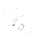
Fig. 1 is the cross sectional drawing along 1-1 line among Fig. 2.
Fig. 2 is the lateral plan of the Webbing take-up device main portion of an embodiment of the present invention.
Fig. 3 is the oblique drawing of the Webbing take-up device main portion of an embodiment of the present invention.
Fig. 4 is the lateral plan of energy absorbing ring of the Webbing take-up device of an embodiment of the present invention.
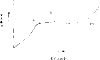
Fig. 5 is the coordinate diagram that concerns between the safety strap amount of pulling out of Webbing take-up device and the harness tension.
Fig. 6 is the cross-sectional side view of the Webbing take-up device main portion of traditional form of implementation.
The optimised form that carries out an invention
Below, according to Fig. 1~Fig. 5, a form of implementation of Webbing take-up device of the present invention is described.
As shown in Figure 2, the pedestal 12 of the Webbing take-up device 10 of this form of implementation is fixed on the vehicle, is that the center can be supported on this pedestal 12 rotationally to safety direction of belt extraction (Fig. 2 arrow A direction) and seat belt winding direction (arrow B direction among Fig. 2) by will be used for the reeling seat belt winding axle 16 of safety strap 14 of other component part of saving in the diagram with axis 18.
Webbing take-up device 10 is in case of emergency can forbid the urgent locked-type security tape winding apparatus (ELR) that safety strap is extracted out at vehicle, because vehicle runs into emergency situation etc. when making device be subjected to impact effect, the same with well-known ELR, jam plate 20 stops the rotation of seat belt winding axle 16 with the 22A of tooth portion engagement, wherein, the 22A of tooth portion is located at the interior perimembranous of ending the energy absorbing gear 22 of picking device as safety strap of ring-type.
Therefore, when energy absorbing gear 22 when the anticlockwise direction (arrow D direction among Fig. 2) of Fig. 2 rotates, energy absorbing steel rope 24 is gone up owing to the peripheral part 22B that is rolled onto energy absorbing gear 22 and is produced plastic deformation, and moves to arrow E direction and arrow F direction.
As shown in Figure 1, energy absorbing gear 22 is provided in the 12A of the pair of sidewalls portion outside of pedestal 12 respectively, and with energy absorbing ring 34 screws thread fit, and energy absorbing ring 34 member that to be 12A of pair of sidewalls portion of being installed in pedestal 12 respectively go up and be fixed on the pedestal.
As shown in Figure 3, energy absorbing ring 34 is positioned at ground, the outside with bead 34A and inserts circular hole 36, and circular hole 36 is located on the side wall portion 12A of pedestal 12; 3 spline pawls 38 that are formed at peripheral part 34 shame cooperate with 3 otch 40 that are formed at circular hole 36 edge portions respectively.Be noted that in Fig. 3 two groups of energy absorbing gears 22 in the 12A of the pair of sidewalls portion outside that is provided in pedestal 12 of only having drawn respectively and energy absorbing ring 34 wherein one group in addition.
As shown in Figure 4, the spline pawl 38 of energy absorbing ring 34 is equally spaced to form 3 in a circumferential direction.
As shown in Figure 1, on each spline pawl 38, squeeze into rivet 42, energy absorbing ring 34 can not split away off from pedestal 12 from the inboard of pedestal 12.Form negative thread 44 on the interior week of energy absorbing ring 34, this negative thread 44 is the 1st screw threads that constitute a rolling-in load holding device part; Form outside thread 46 on energy absorbing gear 22, this outside thread 46 is the 2nd screw threads that constitute a rolling-in load holding device part.The part of above-mentioned outside thread 46 cooperates with above-mentioned negative thread 44.And outside thread 46 is formed on the periphery of cylindrical portion 22C, and cylindrical portion 22C is axially outstanding to the side direction (left direction of Fig. 1) of pedestal 12 along it from energy absorbing gear 22.In addition, between energy absorbing gear 22 and energy absorbing ring 34, form gap L.
On the end face 34C of the opposite side with bead 34A of energy absorbing ring 34, fixedly safety pin 50, and safety pin 50 is the rotation preventive mechanism that constitute a rolling-in load holding device part.End face and this safety pin 50 of the protuberance 22C of energy absorbing gear 22 join, and stop 22 rotations to the safety direction of belt extraction of energy absorbing gear.Rotate to the A of Fig. 2 direction at energy absorbing gear 22, and it is mobile to the left direction (direction shown in the arrow H among Fig. 1) of Fig. 1, the power that acts on the safety pin 50 increases under the above situation of setting, safety pin 50 will be to arrow H direction folding in the past, thereby allow energy absorbing gear 22 to move to arrow H direction, i.e. energy absorption gear 22 can rotate to the arrow A direction.
Below, the operating principle of this form of implementation is described.
To Webbing take-up device 10 of the present invention, when vehicle runs into emergency situation etc. and makes device be subjected to impact effect, the 22A of the tooth portion engagement of the jam plate 20 of seat belt winding axle 16 and energy absorbing gear 22, seat belt winding axle 16 is lockable.At this moment, be that safety pin 50 and energy absorbing steel rope 24 stop the rotation of energy absorbing gear 22.
Under this state, rolling-in load increase when safety strap 14, when the outside thread 46 of energy absorbing gear 22 increases to negative thread 44 precessing forces of energy absorbing ring 34, because energy absorbing gear 22 makes safety pin 50 be subjected to the above power effect of setting value that surpasses of arrow H direction among Fig. 1, makes safety pin 50 to arrow H direction folding in the past.Thus, energy absorbing gear 22 can be moved to arrow H direction, i.e. energy absorption gear 22 can rotate to precession direction (direction of arrow A).
Therefore, the binding force of energy absorbing gear 22 resistance energy absorbing steel ropes 24 and the energy absorbing steel rope 24 that will be drawn out of owing to plastic deformation on one side on peripheral part 22B, on one side in Fig. 2 the direction of arrow D rotate.Thus, the direction of seat belt winding axle 16 arrow D in Fig. 2 is rotated, and safety strap 14 is drawn out of.
When energy absorbing gear 22 further rotates, when making energy absorbing gear 22 outside threads 46 screw in the negative thread 44 of energy absorbing ring 34 fully, gap between energy absorbing gear 22 and the energy absorbing ring 34 disappears, and the rotation of energy absorbing gear 22 stops, and safety strap 14 stops to extract out.
That is, as shown in Figure 5, before the some P1 that energy absorbing gear 22 begins to rotate, the safety strap amount of pulling out roughly rises with harness tension with being directly proportional.At this moment, because the 22A of tooth portion of energy absorbing gear 22 and jam plate 20 engagements, so the reason of the safety strap amount of pulling out increase is owing to safety strap is made safety strap pull out and extend by rolling-in and tension force.
Then, at a P1 place, safety pin 50 can move energy absorbing gear 22 to arrow H direction to arrow H direction folding in the past, i.e. energy absorption gear 22 can rotate to the direction of arrow A.Thus, the energy absorbing steel rope 24 peripheral part 22B that is rolled to energy absorbing gear 22 goes up and slowly extracts out owing to plastic deformation makes safety strap.Therefore, shown in the line part S1 behind the P1, like that, can keep harness tension not continue to rise.
Next, mobile end, the mobile end time is exactly 22 irremovable times of energy absorbing gear (when the gap among Fig. 1 disappears), because screwing of the outside thread 46 of the negative thread 44 of energy absorbing ring 34 and energy absorbing gear 22 stops the rotation of energy absorbing gear 22.So, shown in the follow-up curve part of Fig. 5 cathetus S1 of portion, like that,, can make action slowly stop (the extraction amount no longer increases), and harness tension (safety strap rolling-in load) can increase smoothly along with the increase that screws moment of torsion.
Therefore, in the Webbing take-up device 10 of this form of implementation, can absorb gap L between gear 22 and the energy absorbing ring 34 by energization, in case of emergency the safety strap extraction amount than traditional form of implementation is big at vehicle to make safety strap extraction amount.So, can guarantee the best safety strap amount of pulling out.
More than, particular implementation form of the present invention is had been described in detail, but the present invention being not limited to this form of implementation, the colleague dealer understands that other various forms of implementation can be arranged within the scope of the invention.For example, in this form of implementation, energy absorbing ring 34 respectively is a discrete item with pedestal 12, but also energy absorbing ring 34 and pedestal 12 can be designed to one.In addition, can adopt the elongate member of extending to replace energy absorbing steel rope 24 because of plastic deformation.
The possibility of utilizing on the industry
As mentioned above, Webbing take-up device of the present invention can be used as for the protection of automobile etc. Be sitting in the Webbing take-up device of the seat belt of the occupant on the chair on the vehicle, particularly suitable Be used for having being subjected to acceleration more than the predetermined value and do the time spent with the function of safety belt locking Webbing take-up device.
Claims (4)
1. a Webbing take-up device is characterized in that being provided with: be fixed on the pedestal (12) on the vehicle; Seat belt winding axle (16) is contained in rotationally and is used to the safety strap of reeling on the said base; Safety strap ends picking device (22), be provided with and be contained on the above-mentioned seat belt winding axle jam plate (20) ingear tooth portion (22A) and at vehicle the engagement by jam plate and tooth portion in case of emergency stops the seat belt winding axle to rotate; Rolling-in load holding device (24,44,46,50) increases to setting value when above at the rolling-in load of safety strap, allows that above-mentioned safety strap ends picking device and rotates and the rolling-in load is kept roughly certain to the safety direction of belt extraction.
2. Webbing take-up device as claimed in claim 1 is characterized in that: above-mentioned rolling-in load holding device comprises said base and above-mentioned safety strap is ended elongate member (24), the 1st screw thread (44) that is located at the said base side that picking device couples together, is located at above-mentioned safety strap and ends on the picking device with the 2nd screw thread the 1st screw thread fit (46) and stop safety strap to end the rotation preventive mechanism (50) of picking device to the rotation of safety direction of belt extraction; Increase to setting value when above at the rolling-in of safety strap load, above-mentioned rotation preventive mechanism is destroyed, and above-mentioned the 2nd screw thread moves along above-mentioned the 1st screw thread, can make above-mentioned safety strap end picking device and rotate relative to said base.
3. Webbing take-up device as claimed in claim 2 is characterized in that: above-mentioned the 1st screw thread (44) is a negative thread, is formed on the member that is fixed on the said base; Above-mentioned the 2nd screw thread (46) is an outside thread; Be screwed into above-mentioned the 1st screw thread (44) by above-mentioned the 2nd screw thread (46), make above-mentioned safety strap end the rotation of picking device (22) after above-mentioned rotation preventive mechanism (50) is destroyed and stop.
4. Webbing take-up device as claimed in claim 3 is characterized in that: above-mentioned rotation preventive mechanism is safety pin (50), is located on the member that is fixed on the said base.
Applications Claiming Priority (2)
| Application Number | Priority Date | Filing Date | Title |
|---|---|---|---|
| JP31243995 | 1995-11-30 | ||
| JP312439/95 | 1995-11-30 |
Publications (2)
| Publication Number | Publication Date |
|---|---|
| CN1203554A CN1203554A (en) | 1998-12-30 |
| CN1080217C true CN1080217C (en) | 2002-03-06 |
Family
ID=18029221
Family Applications (1)
| Application Number | Title | Priority Date | Filing Date |
|---|---|---|---|
| CN96198696A Expired - Fee Related CN1080217C (en) | 1995-11-30 | 1996-11-29 | Wedding take-up device |
Country Status (8)
| Country | Link |
|---|---|
| US (1) | US5975451A (en) |
| EP (1) | EP0864471B1 (en) |
| JP (1) | JP3149438B2 (en) |
| KR (1) | KR100276677B1 (en) |
| CN (1) | CN1080217C (en) |
| CA (1) | CA2237718C (en) |
| DE (1) | DE69631966T2 (en) |
| WO (1) | WO1997019837A1 (en) |
Cited By (1)
| Publication number | Priority date | Publication date | Assignee | Title |
|---|---|---|---|---|
| CN102171072A (en) * | 2008-10-02 | 2011-08-31 | 奥托立夫开发公司 | Force limiting device for a motor vehicle |
Families Citing this family (16)
| Publication number | Priority date | Publication date | Assignee | Title |
|---|---|---|---|---|
| JPH11192923A (en) * | 1998-01-06 | 1999-07-21 | Takata Kk | Seat belt retractor |
| DE29811662U1 (en) * | 1998-06-30 | 1998-11-05 | Trw Repa Gmbh | Belt retractor for a vehicle seat belt |
| DE29816280U1 (en) * | 1998-09-10 | 1999-01-21 | Trw Repa Gmbh | Force limiting device |
| DE10015048C5 (en) * | 2000-03-25 | 2008-09-25 | Autoliv Development Ab | Belt retractor with a designed as a sheet metal brake power limiting device |
| DE20110423U1 (en) * | 2000-06-29 | 2001-10-11 | Autoliv Dev | Belt retractor with double-acting force limiting device |
| JP3754283B2 (en) * | 2000-08-15 | 2006-03-08 | 株式会社東海理化電機製作所 | Webbing take-up device |
| JP4559666B2 (en) * | 2001-07-11 | 2010-10-13 | 株式会社東海理化電機製作所 | Webbing take-up device |
| GB2387575B (en) * | 2002-04-16 | 2004-04-14 | Breed Automotive Tech | Retractor |
| DE10308167A1 (en) * | 2003-02-20 | 2004-09-02 | Takata-Petri (Ulm) Gmbh | Fastening device for a seat belt |
| US20050224622A1 (en) * | 2004-03-30 | 2005-10-13 | Zolkower Jeffry N | Dual level load limiting belt retractor with improved load switching |
| JP2005289320A (en) * | 2004-04-05 | 2005-10-20 | Tokai Rika Co Ltd | Webbing take-up device |
| DE102004048455B4 (en) * | 2004-10-05 | 2009-01-08 | Fraunhofer-Gesellschaft zur Förderung der angewandten Forschung e.V. | Device and method for streamlining a safety belt for occupant protection in a vehicle |
| KR100896924B1 (en) | 2007-12-14 | 2009-05-11 | 현대자동차주식회사 | Device of seat belt |
| DE102008059386B3 (en) * | 2008-11-27 | 2010-07-01 | Autoliv Development Ab | Belt retractor with a force limiting device |
| DE102009012565A1 (en) * | 2009-03-11 | 2010-09-16 | Trw Automotive Gmbh | retractor |
| US20180222440A1 (en) * | 2015-07-13 | 2018-08-09 | Key Safety Systems, Inc. | Retractor with Crushable Spool Insert |
Citations (3)
| Publication number | Priority date | Publication date | Assignee | Title |
|---|---|---|---|---|
| JPS5299519A (en) * | 1976-02-17 | 1977-08-20 | Nsk Warner Kk | Energy absorbing retractor |
| JPS5439827A (en) * | 1977-09-06 | 1979-03-27 | Toshiba Corp | Magnetic shielding device for electric machine |
| JPH081310A (en) * | 1994-06-09 | 1996-01-09 | Akechi Ceramics Kk | Manufacture of trough for molten metal |
Family Cites Families (12)
| Publication number | Priority date | Publication date | Assignee | Title |
|---|---|---|---|---|
| JPS5439827U (en) * | 1977-08-24 | 1979-03-16 | ||
| JPS54166621U (en) * | 1978-05-15 | 1979-11-22 | ||
| JPS6111085Y2 (en) * | 1979-10-16 | 1986-04-08 | ||
| JPH07122741B2 (en) | 1987-07-28 | 1995-12-25 | 富士写真フイルム株式会社 | Silver halide color photographic coupler, silver halide color photographic light-sensitive material and color image forming method |
| JPH0355618A (en) * | 1989-07-25 | 1991-03-11 | Fujitsu Ltd | Control system for item input keyboard |
| JPH07115626B2 (en) | 1989-11-17 | 1995-12-13 | 日産自動車株式会社 | Mounting structure for vehicle seat belt retractor |
| JP3247896B2 (en) * | 1991-09-19 | 2002-01-21 | 三井化学株式会社 | Method for producing hydroxyapatite |
| JPH05299519A (en) * | 1992-04-20 | 1993-11-12 | Hitachi Ltd | Manufacture of semiconductor integrated circuit device |
| JP3370397B2 (en) | 1993-10-06 | 2003-01-27 | タカタ株式会社 | Seat belt retractor |
| US5547143A (en) * | 1994-08-24 | 1996-08-20 | Alliedsignal Inc. | Seat belt retractor with integrated load limiter |
| JP3980078B2 (en) * | 1994-09-07 | 2007-09-19 | タカタ株式会社 | Seat belt retractor |
| US5687925A (en) * | 1996-06-27 | 1997-11-18 | Trw Vehicle Safety Systems Inc. | Seat belt retractor with energy management |
-
1996
- 1996-11-29 DE DE69631966T patent/DE69631966T2/en not_active Expired - Lifetime
- 1996-11-29 EP EP96939327A patent/EP0864471B1/en not_active Expired - Lifetime
- 1996-11-29 WO PCT/JP1996/003508 patent/WO1997019837A1/en active IP Right Grant
- 1996-11-29 US US09/077,449 patent/US5975451A/en not_active Expired - Fee Related
- 1996-11-29 KR KR1019980704047A patent/KR100276677B1/en not_active IP Right Cessation
- 1996-11-29 CA CA002237718A patent/CA2237718C/en not_active Expired - Fee Related
- 1996-11-29 JP JP52036997A patent/JP3149438B2/en not_active Expired - Fee Related
- 1996-11-29 CN CN96198696A patent/CN1080217C/en not_active Expired - Fee Related
Patent Citations (3)
| Publication number | Priority date | Publication date | Assignee | Title |
|---|---|---|---|---|
| JPS5299519A (en) * | 1976-02-17 | 1977-08-20 | Nsk Warner Kk | Energy absorbing retractor |
| JPS5439827A (en) * | 1977-09-06 | 1979-03-27 | Toshiba Corp | Magnetic shielding device for electric machine |
| JPH081310A (en) * | 1994-06-09 | 1996-01-09 | Akechi Ceramics Kk | Manufacture of trough for molten metal |
Cited By (2)
| Publication number | Priority date | Publication date | Assignee | Title |
|---|---|---|---|---|
| CN102171072A (en) * | 2008-10-02 | 2011-08-31 | 奥托立夫开发公司 | Force limiting device for a motor vehicle |
| CN102171072B (en) * | 2008-10-02 | 2013-08-07 | 奥托立夫开发公司 | Load limiting device for a motor vehicle |
Also Published As
| Publication number | Publication date |
|---|---|
| CN1203554A (en) | 1998-12-30 |
| KR19990071769A (en) | 1999-09-27 |
| DE69631966T2 (en) | 2005-01-05 |
| CA2237718A1 (en) | 1997-06-05 |
| US5975451A (en) | 1999-11-02 |
| WO1997019837A1 (en) | 1997-06-05 |
| EP0864471B1 (en) | 2004-03-24 |
| EP0864471A1 (en) | 1998-09-16 |
| EP0864471A4 (en) | 2002-04-10 |
| JP3149438B2 (en) | 2001-03-26 |
| CA2237718C (en) | 2002-01-29 |
| DE69631966D1 (en) | 2004-04-29 |
| KR100276677B1 (en) | 2001-04-02 |
Similar Documents
| Publication | Publication Date | Title |
|---|---|---|
| CN1080217C (en) | Wedding take-up device | |
| JPS6111085Y2 (en) | ||
| EP0627345B1 (en) | Safety belt retractor | |
| DE19814604B4 (en) | pretensioners | |
| DE4331027C2 (en) | Belt retractor-belt tensioner combination with force limiter | |
| EP1507688B1 (en) | Safety belt retractor comprising a pre-tensioning device | |
| DE3040667C2 (en) | ||
| CN101077705A (en) | Seatbelt webbing lock preventing apparatus | |
| CN1139505C (en) | Slding mechanism for safety belt extending device of chair | |
| CN1118392C (en) | Retractor for vehicles | |
| US5098030A (en) | Pretensioner in seat belt apparatus | |
| US6497379B2 (en) | Seat belt retractor | |
| US20120049500A1 (en) | Dual Stage Pretensioning and High Pay-In Capacity Pretensioning Retractor | |
| CN1305716C (en) | Seat belt retractor | |
| DE10010379A1 (en) | Safety belt system for motor vehicles has belt winder with winder shaft, gas generator, shaft drive, and simple coupling mechanism | |
| DE3907888A1 (en) | VEHICLE SAFETY BELT TENSIONER | |
| DE4202151C2 (en) | Seat belt retractor | |
| DE102016112425A1 (en) | Acceleration sensor and belt retractor | |
| US20100213302A1 (en) | Retractor assembly | |
| WO2001085495A2 (en) | Safety belt winder with a reversible belt tensioner | |
| DE4423958A1 (en) | Belt retractor | |
| US20030235466A1 (en) | Method and apparatus for a minimally aggressive vehicle stopping system | |
| DE102004022401B4 (en) | Belt retractor with pre-tensioner drive | |
| DE3600004A1 (en) | Rotary belt tightening device for safety belts | |
| US11059451B2 (en) | Seat belt retractor with auxiliary spool locking system |
Legal Events
| Date | Code | Title | Description |
|---|---|---|---|
| C06 | Publication | ||
| PB01 | Publication | ||
| C10 | Entry into substantive examination | ||
| SE01 | Entry into force of request for substantive examination | ||
| C14 | Grant of patent or utility model | ||
| GR01 | Patent grant | ||
| C17 | Cessation of patent right | ||
| CF01 | Termination of patent right due to non-payment of annual fee |
Granted publication date: 20020306 Termination date: 20101129 |