CN1080004C - Electric member having leads - Google Patents
Electric member having leads Download PDFInfo
- Publication number
- CN1080004C CN1080004C CN95108511A CN95108511A CN1080004C CN 1080004 C CN1080004 C CN 1080004C CN 95108511 A CN95108511 A CN 95108511A CN 95108511 A CN95108511 A CN 95108511A CN 1080004 C CN1080004 C CN 1080004C
- Authority
- CN
- China
- Prior art keywords
- lead
- loosening
- wire
- prevents
- fixing knot
- Prior art date
- Legal status (The legal status is an assumption and is not a legal conclusion. Google has not performed a legal analysis and makes no representation as to the accuracy of the status listed.)
- Expired - Fee Related
Links
- 238000000034 method Methods 0.000 claims description 25
- 238000004519 manufacturing process Methods 0.000 claims description 22
- 238000003780 insertion Methods 0.000 claims description 6
- 230000037431 insertion Effects 0.000 claims description 6
- 238000003825 pressing Methods 0.000 abstract description 2
- 230000002265 prevention Effects 0.000 abstract 4
- 239000013307 optical fiber Substances 0.000 description 75
- 230000014509 gene expression Effects 0.000 description 17
- 230000003287 optical effect Effects 0.000 description 14
- 230000015572 biosynthetic process Effects 0.000 description 8
- 230000000694 effects Effects 0.000 description 8
- 239000000463 material Substances 0.000 description 6
- 238000003466 welding Methods 0.000 description 5
- 238000011017 operating method Methods 0.000 description 4
- 229910000679 solder Inorganic materials 0.000 description 4
- 238000005452 bending Methods 0.000 description 3
- 238000010586 diagram Methods 0.000 description 3
- 238000005516 engineering process Methods 0.000 description 3
- 238000005520 cutting process Methods 0.000 description 2
- 238000009434 installation Methods 0.000 description 2
- NJPPVKZQTLUDBO-UHFFFAOYSA-N novaluron Chemical compound C1=C(Cl)C(OC(F)(F)C(OC(F)(F)F)F)=CC=C1NC(=O)NC(=O)C1=C(F)C=CC=C1F NJPPVKZQTLUDBO-UHFFFAOYSA-N 0.000 description 2
- 238000007639 printing Methods 0.000 description 2
- 230000005540 biological transmission Effects 0.000 description 1
- 230000015556 catabolic process Effects 0.000 description 1
- 230000008602 contraction Effects 0.000 description 1
- 238000005260 corrosion Methods 0.000 description 1
- 230000007797 corrosion Effects 0.000 description 1
- 238000006731 degradation reaction Methods 0.000 description 1
- 230000000881 depressing effect Effects 0.000 description 1
- 238000013461 design Methods 0.000 description 1
- 238000005538 encapsulation Methods 0.000 description 1
- 238000012856 packing Methods 0.000 description 1
- 238000002360 preparation method Methods 0.000 description 1
- 239000011347 resin Substances 0.000 description 1
- 229920005989 resin Polymers 0.000 description 1
- 238000005476 soldering Methods 0.000 description 1
- 239000000758 substrate Substances 0.000 description 1
Images


Classifications
-
- H—ELECTRICITY
- H04—ELECTRIC COMMUNICATION TECHNIQUE
- H04B—TRANSMISSION
- H04B10/00—Transmission systems employing electromagnetic waves other than radio-waves, e.g. infrared, visible or ultraviolet light, or employing corpuscular radiation, e.g. quantum communication
-
- H—ELECTRICITY
- H01—ELECTRIC ELEMENTS
- H01J—ELECTRIC DISCHARGE TUBES OR DISCHARGE LAMPS
- H01J5/00—Details relating to vessels or to leading-in conductors common to two or more basic types of discharge tubes or lamps
- H01J5/02—Vessels; Containers; Shields associated therewith; Vacuum locks
-
- H—ELECTRICITY
- H01—ELECTRIC ELEMENTS
- H01R—ELECTRICALLY-CONDUCTIVE CONNECTIONS; STRUCTURAL ASSOCIATIONS OF A PLURALITY OF MUTUALLY-INSULATED ELECTRICAL CONNECTING ELEMENTS; COUPLING DEVICES; CURRENT COLLECTORS
- H01R43/00—Apparatus or processes specially adapted for manufacturing, assembling, maintaining, or repairing of line connectors or current collectors or for joining electric conductors
- H01R43/04—Apparatus or processes specially adapted for manufacturing, assembling, maintaining, or repairing of line connectors or current collectors or for joining electric conductors for forming connections by deformation, e.g. crimping tool
- H01R43/042—Hand tools for crimping
- H01R43/0424—Hand tools for crimping with more than two radially actuated mandrels
-
- H—ELECTRICITY
- H05—ELECTRIC TECHNIQUES NOT OTHERWISE PROVIDED FOR
- H05K—PRINTED CIRCUITS; CASINGS OR CONSTRUCTIONAL DETAILS OF ELECTRIC APPARATUS; MANUFACTURE OF ASSEMBLAGES OF ELECTRICAL COMPONENTS
- H05K3/00—Apparatus or processes for manufacturing printed circuits
- H05K3/30—Assembling printed circuits with electric components, e.g. with resistor
- H05K3/306—Lead-in-hole components, e.g. affixing or retention before soldering, spacing means
- H05K3/308—Adaptations of leads
-
- Y—GENERAL TAGGING OF NEW TECHNOLOGICAL DEVELOPMENTS; GENERAL TAGGING OF CROSS-SECTIONAL TECHNOLOGIES SPANNING OVER SEVERAL SECTIONS OF THE IPC; TECHNICAL SUBJECTS COVERED BY FORMER USPC CROSS-REFERENCE ART COLLECTIONS [XRACs] AND DIGESTS
- Y10—TECHNICAL SUBJECTS COVERED BY FORMER USPC
- Y10S—TECHNICAL SUBJECTS COVERED BY FORMER USPC CROSS-REFERENCE ART COLLECTIONS [XRACs] AND DIGESTS
- Y10S72/00—Metal deforming
- Y10S72/712—Electrical terminal crimper
-
- Y—GENERAL TAGGING OF NEW TECHNOLOGICAL DEVELOPMENTS; GENERAL TAGGING OF CROSS-SECTIONAL TECHNOLOGIES SPANNING OVER SEVERAL SECTIONS OF THE IPC; TECHNICAL SUBJECTS COVERED BY FORMER USPC CROSS-REFERENCE ART COLLECTIONS [XRACs] AND DIGESTS
- Y10—TECHNICAL SUBJECTS COVERED BY FORMER USPC
- Y10T—TECHNICAL SUBJECTS COVERED BY FORMER US CLASSIFICATION
- Y10T29/00—Metal working
- Y10T29/49—Method of mechanical manufacture
- Y10T29/49002—Electrical device making
- Y10T29/49117—Conductor or circuit manufacturing
- Y10T29/49124—On flat or curved insulated base, e.g., printed circuit, etc.
- Y10T29/4913—Assembling to base an electrical component, e.g., capacitor, etc.
- Y10T29/49139—Assembling to base an electrical component, e.g., capacitor, etc. by inserting component lead or terminal into base aperture
- Y10T29/4914—Assembling to base an electrical component, e.g., capacitor, etc. by inserting component lead or terminal into base aperture with deforming of lead or terminal
- Y10T29/49142—Assembling to base an electrical component, e.g., capacitor, etc. by inserting component lead or terminal into base aperture with deforming of lead or terminal including metal fusion
-
- Y—GENERAL TAGGING OF NEW TECHNOLOGICAL DEVELOPMENTS; GENERAL TAGGING OF CROSS-SECTIONAL TECHNOLOGIES SPANNING OVER SEVERAL SECTIONS OF THE IPC; TECHNICAL SUBJECTS COVERED BY FORMER USPC CROSS-REFERENCE ART COLLECTIONS [XRACs] AND DIGESTS
- Y10—TECHNICAL SUBJECTS COVERED BY FORMER USPC
- Y10T—TECHNICAL SUBJECTS COVERED BY FORMER US CLASSIFICATION
- Y10T29/00—Metal working
- Y10T29/49—Method of mechanical manufacture
- Y10T29/49002—Electrical device making
- Y10T29/49117—Conductor or circuit manufacturing
- Y10T29/49124—On flat or curved insulated base, e.g., printed circuit, etc.
- Y10T29/49147—Assembling terminal to base
- Y10T29/49151—Assembling terminal to base by deforming or shaping
- Y10T29/49153—Assembling terminal to base by deforming or shaping with shaping or forcing terminal into base aperture
-
- Y—GENERAL TAGGING OF NEW TECHNOLOGICAL DEVELOPMENTS; GENERAL TAGGING OF CROSS-SECTIONAL TECHNOLOGIES SPANNING OVER SEVERAL SECTIONS OF THE IPC; TECHNICAL SUBJECTS COVERED BY FORMER USPC CROSS-REFERENCE ART COLLECTIONS [XRACs] AND DIGESTS
- Y10—TECHNICAL SUBJECTS COVERED BY FORMER USPC
- Y10T—TECHNICAL SUBJECTS COVERED BY FORMER US CLASSIFICATION
- Y10T29/00—Metal working
- Y10T29/49—Method of mechanical manufacture
- Y10T29/49002—Electrical device making
- Y10T29/49117—Conductor or circuit manufacturing
- Y10T29/49174—Assembling terminal to elongated conductor
- Y10T29/49181—Assembling terminal to elongated conductor by deforming
- Y10T29/49183—Assembling terminal to elongated conductor by deforming of ferrule about conductor and terminal
-
- Y—GENERAL TAGGING OF NEW TECHNOLOGICAL DEVELOPMENTS; GENERAL TAGGING OF CROSS-SECTIONAL TECHNOLOGIES SPANNING OVER SEVERAL SECTIONS OF THE IPC; TECHNICAL SUBJECTS COVERED BY FORMER USPC CROSS-REFERENCE ART COLLECTIONS [XRACs] AND DIGESTS
- Y10—TECHNICAL SUBJECTS COVERED BY FORMER USPC
- Y10T—TECHNICAL SUBJECTS COVERED BY FORMER US CLASSIFICATION
- Y10T29/00—Metal working
- Y10T29/49—Method of mechanical manufacture
- Y10T29/49002—Electrical device making
- Y10T29/49117—Conductor or circuit manufacturing
- Y10T29/49204—Contact or terminal manufacturing
- Y10T29/49208—Contact or terminal manufacturing by assembling plural parts
- Y10T29/49218—Contact or terminal manufacturing by assembling plural parts with deforming
Abstract
In an electric member having a number of leads such as in a remote-controlled light receiving module, loosening prevention kinks created on at least one of the leads are shaped such that the shorter the distance from the loosening prevention kink to the tip of the lead the thinner the loosening prevention kink. When the electric member is mounted on a printed circuit board, the leads are inserted into wiring through-holes on the printed circuit board by pressing the electric member against the board, allowing the position and orientation of the electric member to be firmly fixed automatically by virtue of the loosening prevention kinks.
Description
The present invention relates to a kind of manufacture method with electronic unit and this electronic unit of a plurality of leads.
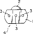
What Figure 1A and 1B represented is a kind of typical remote control optical fiber receive module 4, and it is used to receive the infrared light from the transmission remote signal of remote-operated controller.
Reference number 1 expression is that shape is a cubical shell substantially among the figure.Shell 1 is made by the resin that infrared light can see through.The receiver of remote-control sytem IC that is sealed in shell 1 the inside does not show in the drawings.Lens of reference number 2 expression, it has a protruding ball surface, and this surface is that an integral part as shell 1 front surface constitutes.Lens 2 are positioned on the position on the optical receiving surface of receiver of remote-control sytem IC, and this position is for being best being focused on the infrared light of remote signal modulation by remote controller place.
Each reference number 3 represents that all one is stretched and the vertical lead-in wire of this lower surface from shell 1 lower surface.In general remote control optical fiber receive module 4, the cross sectional shape of these lead-in wires 3 is identical at the lower surface place of lead-in wire 3 shells of therefrom stretching 1 with size at least.Lead-in wire 3 be the lower surface from shell 1 straight stretch formation.
A kind of like this remote control optical fiber receive module 4 is contained in the remote control, as television receiver, magnetic tape recorder and air conditioner.Specifically, need exactly to weld together plug wire hole predetermined on the outer end insertion printed wiring board of remote control optical fiber receive module 4 lead-in wires 3 and the line on lead-in wire and the wiring board.
Fig. 2 represents is how general remote control optical fiber receive module 4 to be installed to a kind of typical case on the printed wiring board.Reference number 5 expressions is printed wiring board among the figure, and each reference number 6 all represents to be used on the printed wiring board 5 inserting the lead-in wire patchhole of lead-in wire 3.Scolder of reference number 7 expressions, it is used for the line on lead-in wire 3 that inserts lead-in wire patchhole 6 and the printed wiring board 5 is coupled together.
Socket of reference number 8 expressions is equipped with remote control optical fiber receive module 4 in this socket.Socket 8 plays a fixedly effect of the position of remote control optical fiber receive module 4, specifically, makes the height of remote control optical fiber receive module 4 be positioned at the position, surface of printed wiring board 5 exactly.In addition, socket 8 also plays the fixedly effect of the orientation of remote control optical fiber receive module 4, specifically, fixes its optical axis direction exactly.That is to say that because remote control optical fiber receive module 4 has a kind of directionality, so its position and optical axis all are important factors, these factors can influence from the receive mode of remote-operated controller by the infrared light of the remote signal modulation of Optical devices.Therefore, just need remote control optical fiber receive module 4 be installed on the printed wiring board 5 in predetermined in advance mode.
As previously described, in general remote control optical fiber receive module 4 shown in Figure 1, the shape in a plurality of leads 3 cross sections is identical at the lower surface place of lead-in wire 3 shells of therefrom stretching 1 with size at least.Lead-in wire 3 is straight to stretch from the lower surface of shell 1.Therefore, even lead-in wire 3 is inserted in the wire jacks 6, owing between general remote control optical fiber receive module 4 and printed wiring 5, have the gap, so general remote control optical fiber receive module 4 still has rocking to a certain degree.Consequently, the position of general remote control optical fiber receive module 4 relative printed wiring boards 5 and orientation are not that real fixed is constant.Therefore, in general remote control optical fiber receive module 4, inevitably can take place loosening and move the position.Become flexible and just mean the direction run-off the straight that optical axis is set relatively.This being tilted in will be avoided in the optical system taking place.Much less the position is moved and is not also wished to take place.For fear of this loosening generation of moving, adopt socket 8 to be used for the firmly fixedly position and the orientation of remote control optical fiber receive module 4 with the position.
Socket 8 has one pin 9 insertion wire jacks 6 are installed.Hook-type nail 10 of reference number 10 expression, nail 10 is formed on the end that pin 9 is installed, and the back surfaces (or not the side of socket object pedestal) that is used at printed wiring board 5 is hooked pin 9 is installed.What reference number 11 was represented is a stopper thing of installing on the pin 9, and stopper thing 11 is positioned at the hook-type that leaves installation pin 9 ends to be followed closely on the position of 10 certain distances, and this distance approximates the thickness of lead-in wire patchhole 6.Stopper thing 11 is used for waling installation pin 9 at the front surface of printed wiring board 5 (the perhaps surface of socket object pedestal side).By pin 9 being installed with stopper thing 11 and hook-type nail 10 waling on printed wiring board 5, just can fixed socket 8 orientation and positions own, this position specifically is exactly the height above printed wiring board 5.Socket 8 can firmly keep the position and the orientation of remote control optical fiber receive module 4 again like this.That is to say, according to predetermined fixing of socket 8, just fixedly remote control optical fiber receive module 4 with respect to the position and the orientation of printed wiring board 5.On this position and this orientation, the lead-in wire 3 of anti-remote control optical fiber receive module 4 welds together with the line of printed wiring board 5.
By the way, because the position of the general remote control optical fiber receive module 4 shown in Figure 1A and the 1B and orientation fix by using socket 8, so, the problem of being said below also will considering.
At first, use socket 8 problem of cost can occur increasing.
More particularly, for the remote control equipment that being starved of resemble the television equipment reduces cost, just need to make great efforts to reduce the step of number of components and assembly operation.In general remote control optical fiber receive module 4, adopt socket 8 only to play the effect of fixing its position, and no matter whether can satisfy above-mentioned such a kind of needs.So it is unallowed using socket 8 like this.
Second problem is, because the position of remote control optical fiber receive module 4 fixes by immersed solder socket 8, lead-in wire 3 can be subjected to the stretching of scolder 7 tensile stresses during immersed solder, so, just a problem appears, promptly stress can be applied to and go between 3 the welding the IC chips on.It should be noted that the IC chip itself is inserted the inside of shell 1, does not show in the drawings.This problem below will be described in more detail.
The position of general remote control optical fiber receive module 4 is fixing by socket 8, and lead-in wire 3 adopts the immersed solder technology to weld.When turning cold, can shrink in scolder 7.The power of this contraction will stretch along direction shown in the arrow a among Fig. 2 and go between 3.
But, because the position of shell 1 is fixing by socket 8, so lead-in wire 3 can not move along direction shown in the arrow a.Consequently, lead-in wire 3 is extracted downwards from shell 1 towards downside shown in Figure 2 inevitably.Like this, can be subjected to the effect of the stress that the shell 1 by encapsulation IC chip passed over again with the IC chip of the welding of lead-in wire in 3.Stress is applied on the IC chip, and can to produce nature be not wish the IC characteristic degradation that occurs, the problem that reliability decrease and disqualification rate rise.
First purpose of the present invention is that cancellation is as a socket that Optical devices are installed.
Second purpose of the present invention provides a kind of new structure, and makes the method for this structure, and this structure has many can fix the position of an optics and the lead-in wire of orientation.
The invention provides a kind of electronic unit, these parts have a plurality of leads, these lead-in wires are inserted into a lead-in wire on the mounting panel that is used to install electronic unit and insert in the hole, this electronic unit is characterised in that, the loosening fixing knot (kink) that prevents is all arranged on every lead-in wire, be used for when lead-in wire being pressed into the lead-in wire patchhole, anchor leg self is with respect to the orientation of mounting panel, the wherein loosening place that prevents fixing knot the closer to the lead-in wire end looseningly prevents that fixing knot is thin more.
The present invention also provides a kind of method of making this electronic unit, the method is characterized in that packs every lead-in wire into is used for constituting the loosening sleeve pipe that prevents fixing knot, by being packed into, lead-in wire is used for constituting the loosening sleeve pipe that prevents fixing knot, by compressing calking and come to prevent that loosening fixing knot is fixed on lead-in wire to being used to constitute the loosening sleeve pipe that prevents fixing knot.
The present invention also provides a kind of method of making this electronic unit, the method is characterized in that every lead-in wire and each are loosening to prevent that fixing knot from being made of simultaneously the planer leads material.
In electronic unit provided by the invention, the loosening fixing knot that prevents is all arranged on its every lead-in wire, the loosening place that prevents fixing knot the closer to the lead-in wire end, become flexible and prevent that fixing knot is thin more, when with box lunch lead-in wire being pressed into the lead-in wire patchhole of mounting panel, the orientation of self the relative mounting panel of going between is fixed.Utilize this electronic unit, earlier the lead-in wire that mounting panel is inserted in the end of lead-in wire inserts in the hole, and then prevents that loosening fixing knot is pressed into the lead-in wire patchhole, with anchor leg firmly with respect to the orientation of mounting panel.Adopt this method just can prevent that lead-in wire is loosening.
In addition, the loosening position of fixing knot on every lead-in wire that prevent just determined this height above mounting panel of electronic unit.The result is that therefore the position of electronic unit also has been fixed naturally.
Therefore, need not use the socket just fixedly position of electronic unit and orientation.
So, in this method, can solve for example because of using socket to fix the position of general remote control optical fiber receive module and the problem that orientation is produced.
As mentioned above, the present invention also provides a kind of method of making this electronic unit, wherein every of electronic unit lead-in wire is all packed into, and being used to form of preparation in advance is loosening to prevent in the fixing sleeve pipe of tying, utilization is packed into and is used to form the loosening lead-in wire that prevents in the fixing sleeve pipe of tying, as long as being compressed calking, sleeve pipe just can form the loosening fixing knot that prevents, and simultaneously it is fixed on the lead-in wire, prevent that fixing knot from forming at an easy rate so that become flexible on lead-in wire.
Consequently, can bootlessly not increase under the situation of production cost, just can make a kind of electronic unit that has many lead-in wires, and on each root of these lead-in wires, all there is one loosening to prevent fixing knot, wherein prevent fixedly the knot fixing position of electronic unit at an easy rate, and prevent becoming flexible of the lead-in wire that when being installed on the printed wiring board, produced to electronic unit with loosening.
As mentioned above, the present invention further provides a kind of method of making this electronic unit, wherein each root lead-in wire of electronic unit becomes flexible with each and prevents that fixing knot from being to form with flat lead material simultaneously, and does not need list to adopt special method to becoming flexible the formation that prevents fixing knot.Consequently, every lead-in wire and loosening prevent that fixing knot all is very easy to formation, and need not to increase manufacturing step.
Figure 1A and 1B are the schematic diagrames of general remote control optical fiber receive module, and expression is front view and ground plan respectively;
Fig. 2 is a schematic diagram, is used to illustrate a kind of typical case how general remote control optical fiber receive module shown in Figure 1A and the 1B is installed;
Fig. 3 A, 3B and 3C are the forward sights of a kind of remote control optical fiber receive module first embodiment, and top view and side view, Fig. 3 D are the loosening front views that prevents fixing knot;
Fig. 4 is a sectional view, expression be a kind ofly how Fig. 3 A to be installed to typical case on the bar printing wiring board to the remote control optical fiber receive module shown in the 3D;
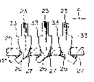
Fig. 5 A is the perspective view of implementing second embodiment of a kind of manufacture method of the present invention to 5C, expression be to make as Fig. 3 A to primary element of the remote control optical fiber receive module shown in the 3D, and on its lead-in wire, form the loosening operating procedure order that prevents the method for fixing knot;
Fig. 6 is a perspective view, expression be the 3rd embodiment of remote control optical fiber receive module of the present invention;
Fig. 7 A is a perspective view of implementing the 4th embodiment of manufacture method of the present invention to 7B, expression be to make as a primary element of remote control optical fiber receive module shown in Figure 6 and on its lead-in wire, form the loosening operating procedure order that prevents the method for fixing knot;
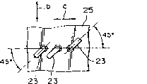
That Fig. 8 A represents to 8C is the 5th embodiment of remote control optical fiber receive module of the present invention.Fig. 8 A is the loosening perspective view that prevents fixing knot.Fig. 8 B is the sectional view after the remote control optical fiber receive module is installed on the printing reception line.Fig. 8 C is the ground plan after the remote control optical fiber receive module is installed on the printed substrate.
Below by the detailed description of the above accompanying drawing of reference to most preferred embodiment, it is clearer that the present invention can become.
Fig. 3 A is the schematic diagram of first embodiment of remote control optical fiber receive module to 3D.Fig. 3 A is that it is faced to 3C, top view and side view.Fig. 3 D is the loosening front elevation that prevents fixing knot.
The obvious difference of the general remote control optical fiber receive module shown in remote control optical fiber receive module of the present invention and Figure 1A and the 1B is all to have on the former the every lead-in wire the loosening fixing knot that prevents.Both are basic identical in others.Because both's components identical had been done explanation, just not repeat specification here.Below only both difference is described.In addition, in institute's drawings attached, adopt identical reference number to carry out mark for both's components identical.
Loosening preventing fixed the position that knot 33 is formed on setting on the lead-in wire 23, so that the shell 21 of remote control optical fiber receive module 32 is positioned on the required height and position in printed wiring board 25 tops.
Fig. 4 is a sectional view, expression be a kind ofly how the remote control optical fiber receive module 32 of Fig. 3 to be installed to typical case on the printed wiring board 25.
For remote control optical fiber receive module 32 is installed on the printed wiring board 25, each root of lead-in wire 23 is all inserted in the lead-in wire patchhole 26 corresponding on the printed wiring board 25.Loosening prevent that fixing knot 33 from running into lead-in wire patchhole 26 in, lead-in wire 23 is firmly pressed to printed wiring board 25, so that looseningly prevent that fixing knot 33 from inserting the patchhole 26 that goes between under pressure.Adopt this mode, be pressed into the loosening of lead-in wire patchhole 26 and prevent that fixing knot 33 can be on the direction perpendicular to printed wiring board 25, firmly anchor leg 23 is with respect to the position of lead-in wire patchhole 26.
Consequently, the orientation and the position of 23 shells that therefrom stretch out 21 that go between have also been fixed.Specifically, be exactly in any direction, direction shown in arrow 6 in Fig. 3 D and 4, promptly direction shown in optical axis direction and the arrow C is promptly perpendicular to the direction of optical axis direction, not loosening.
After the orientation and fixed-site of shell 21, as shown in Figure 4, lead-in wire 23 parts that reach printed wiring board 25 belows are cut out suitable length and in the bending of the back side of printed wiring board 25.The insertion of lead-in wire 23, cutting and crooked work typically can automatically be carried out by an insertion machine.
Then, adopting the immersed solder technology to go between 23 is soldered on the line at printed wiring board 25 back sides.Scolder of reference number 27 expressions.
It should be noted, in welding process, be heated the scolder that melted 27 and shunk, as the front was said, can be on downward direction shown in Figure 4 23 produce the convergent force of a stretching going between along with decrease of temperature.But, owing to loosening prevent that fixing knot 33 from taking root dearly and be fixed on the effect of playing the stopper thing in the lead-in wire patchhole 26, so the convergent force that pulls down the line 23 that extends can not be applied to lead-in wire 23 in the loosening part that prevents on the fixing knot 33.Consequently, can never appear at the problem that IC chip in the shell 21 is subjected to the convergent force effect that is encapsulated in that is occurred in the general remote control optical fiber receive module.It should be noted that the IC chip itself does not show in the accompanying drawings.
As mentioned above, by preventing that fixing knot 33 from pressing to printed wiring board 25 and prevent in the lead-in wire patchholes 26 that fixing knot 33 inserts on the printed wiring boards 25 loosening loosening, thereby remote control optical fiber receive module 32 is installed on the printed wiring board 25, wherein, on lead-in wire each root of 23, all there is one looseningly to prevent fixing knot 33, make to become flexible and prevent the end more near places of fixing knot 33 from lead-in wire 23, become flexible and prevent that fixing knot 33 is just thin more, so that when lead-in wire 23 inserts lead-in wire patchholes 26, firmly anchor leg 23 self is with respect to the orientation of printed wiring board 25.Like this, prevent that by lead-in wire patchhole 26 being inserted in a lead-in wire end of 23 and further will becoming flexible fixing knot 33 is pressed into the patchhole 26 that goes between, just can be not the orientation of anchor leg 23 firmly loosely.
Loosening 32 height above printed wiring board 25 of remote control optical fiber receive module that prevented the determining positions of fixing knot 33 on lead-in wire 23.Consequently, therefore remote control optical fiber receive module 32 positions own just have been fixed naturally.Therefore, without the socket just fixedly position of remote control optical fiber receive module 32 and orientation.
The following describes the second embodiment of the present invention.
As mentioned above, Fig. 3 A is characterised in that have one looseningly to prevent fixing knot 33 on lead-in wire each root of 23 to the remote control optical fiber receive module 32 shown in the 3D.So just need on each root of the lead-in wire 23 of the electronic unit of remote control optical fiber receive module 32, all be formed with the loosening fixing knot that prevents.Fig. 5 A is a perspective view to 5C, expression be on lead-in wire 23, to form the loosening fixing knot that prevents, promptly as the operating procedure order of the formation method of the vitals of the electronic unit of a remote control optical fiber receive module 32.
At first, prepare a lead frame, this lead frame comprises the many lead-in wires 23 that are used for remote control optical fiber receive module 32, and these lead-in wires 23 form a branch of.Shown in Fig. 5 A, to be formed with the loosening lead-in wire 23 of fixing knot 33 that prevents above one of lead frame and be enclosed in the sleeve pipe 34, this sleeve pipe 34 is used for preventing to form on fixing knot 33 positions that will locate the loosening fixing knot 33 that prevents loosening.In other words, exactly lead-in wire 23 is inserted in the sleeve pipe 34 to form the loosening fixing knot 33 that prevents.It should be noted, will form the loosening number of the lead-in wire 23 in the fixing lead frame of tying that prevents thereon and change according to applicable cases.In some cases, only on some lead-in wires 23 of lead frame, to form and looseningly prevent fixing knot 33, and under the other situation, on each root of institute leaded 23, all need to be formed with loosening preventing and fixingly tie 33.
In Fig. 5 A, be used to form the loosening sleeve pipe 34 that prevents fixing knot 33 before representing to be enclosed within on the lead-in wire 23 with solid line, and dot the loosening sleeve pipe 34 that prevents fixing knot 33 that is used to form after being enclosed within on the lead-in wire 23.
This lead frame typically all has two caulked stopper things of representing with the circle of imaginary point line 35 in Fig. 5 A.By being packed into lead-in wire 23 along moving on to position that its stopper thing 35 adheres on the lead-in wire 23, sleeve pipe 34 is used to form on the loosening sleeve pipe 34 that prevents fixing knot 33.Adopt this mode, sleeve pipe 34 can be positioned on the correct position.
Next shown in Fig. 5 B, make compress caulking implement 36 be positioned at be enclosed within on the lead-in wire 23 being used to form the loosening sleeve pipe 34 that prevents fixing knot 33 around.Compress caulking implement 36 and comprise that four compress town unit, crack 36a, 36b, 36c and 36d, these four calking unit are separated from each other and are seen as the angle of 90 degree from the center of caulking implement 36. Compress calking unit 36a, 36b, 36c and 36d can leave the center synchronously with one another simultaneously or shift to the centrifugal of center or entad move.Compress calking unit 36a, 36b, each edge of 36c and 36d is of similar shape it and adjacent looseningly prevents that the fixing shape of tying the gap between 33 is identical with two that will form in compressing the calking operation.
Next, shown in Fig. 5 c, drive and compress caulking implement 36 to compress the calking operation, more particularly, drive and compress calking unit 36a, 36b, 36c and 36d entad move, and sleeve pipe 34 is compressed calking to form the loosening fixing knot 33 that prevents.Adopt this mode, also be fixed on the lead-in wire 23 in the fixing knot 33 loosening the preventing of formation.
Then, operation compresses caulking implement 36 and makes the centrifugal mobile lead-in wire 23 that unclamps.
According to forming the loosening method that prevents fixing knot 33, only the loosening sleeve pipe of in advance preparing 34 of fixing knot 33 that prevents that is used to form is enclosed within on the lead-in wire 23, and uses and compress 36 pairs of caulking implements and be used to form the loosening sleeve pipe 34 that prevents fixing knot 33 and compress calking and fixingly tie 33 to form loosening preventing.Adopt this mode, loosening prevent that fixing knot 33 from can form simultaneously and be fixed on the lead-in wire 23.Consequently, can on lead-in wire, form the loosening fixing knot 33 that prevents at an easy rate.
Therefore, can under the situation that does not bootlessly increase production cost, make a kind of remote control optical fiber receive module 32, this remote control optical fiber receive module 32 has many lead-in wires 23, the loosening fixing knot 33 that prevents is all arranged on the every lead-in wire 23, this becoming flexible prevents fixing knot 33 to remote control optical fiber receive module 32 when installing on the printed wiring board 25, can make remote control optical fiber receive module 32 location at an easy rate and can not produce loosening.It should be noted that remote control optical fiber receive module 32 ensuing manufacture processes are identical with the manufacture process of general remote control optical fiber receive module.That is to say, make according to following order: the chips welding of IC chip, line welding, resin-sealed and each remote control optical fiber receive module 32 is separated from each other by cutting lead frame unnecessary portions.
Fig. 6 is a perspective view, expression be the 3rd of remote control optical fiber receive module of the present invention
Embodiment.
As shown in the figure, a remote control optical fiber receive module 32a has some lead-in wires 23, all has a taper to become flexible on each root of these lead-in wires 23 and prevents fixing knot 33a.The present invention also can provide a kind of like this design.
By using-be used to form a loosening sleeve pipe 34a who prevents fixing knot can form also that a kind of like this taper is loosening to prevent fixing knot 33a.Fig. 7 A and 7B are perspective views, expression be the 4th embodiment of the operating procedure order of the loosening method that prevents fixing knot 33a of a kind of taper of manufacturing of the present invention.
At first, prepare a lead frame, this lead frame comprises the many lead-in wires 23 that are used for remote control optical fiber receive module 32a, and these lead-in wires 23 constitute a branch of.Shown in Fig. 7 A, pack into and be used to form among the loosening sleeve pipe 34a that prevents fixing knot 33a being formed with a loosening lead-in wire 23 that prevents the lead frame of fixing knot 33a on it, sleeve pipe 34a is positioned at loosening preventing on the position that fixing knot 33a will locate.In other words, lead-in wire 23 insertions being used to form loosening preventing fixes among the sleeve pipe 34a of knot 33a.It should be noted that the quantity of the lead-in wire 23 that will form the loosening lead frame that prevents fixing knot on it changes according to practical application.In some cases, only on some lead-in wire 33a of lead frame, be formed with and looseningly prevent fixing knot 33a, and under the other situation, all need to form one on each root of institute leaded 23 and looseningly prevent the fixing 33a of knot.
It should be noted, in this electronic unit, lead frame on its each root lead-in wire 23 also caulked two stopper things of being represented by the dotted line circle in Fig. 7 A 35 are arranged.Lead-in wire 23 packed into to be used to form among the loosening sleeve pipe 34a that prevents fixing knot 33a, much less, along moving on to the position that stopper thing 35 adheres on the lead-in wire 23 sleeve pipe 34a is correctly located.
Next, become flexible on the sleeve pipe 34a that prevents fixing knot 33a near being used to form compressing caulking implement 36 location, this sleeve pipe 34a has been enclosed within on the lead-in wire 23.Compress caulking implement 36 comprise a pair of sleeve pipe 34a both sides compress calking unit 36a and 36b, they are separated from each other and are seen as the angles of 180 degree from the center that compresses town's crack instrument 36.34a is clipped in the middle with sleeve pipe, compresses that calking unit 36a and 36b can leave sleeve pipe 34a synchronously with one another simultaneously or centrifugal or entad move towards sleeve pipe 34a.All there is a concave surface at each the edge that compresses calking unit 36a and 36b, and the loosening only about half of outer surface of fixing knot 33a that prevents of this concave surface and taper mates well.
Next, drive and to compress caulking implement 36 to carry out compressing the calking operation shown in Fig. 7 B.More particularly, driving compresses calking unit 36a and 36b presses sleeve pipe 34a from both sides, and clamp sleeve 34a is to form the loosening fixing 33a of knot that prevents on lead-in wire 23.Adopt this mode, form loosening prevent fixing knot 33a in, even it is fixed on the lead-in wire 23.
Then, make and compress centrifugal outer the moving of caulking implement 36 and unclamp lead-in wire 23.
According to the loosening method that prevents knot 33a of this formation, pre-prepd be used to form the loosening sleeve pipe 34a that prevents fixing knot 33a be positioning sleeve on lead-in wire 23, and compress and be used to form the loosening sleeve pipe 34a of fixing knot 33a that prevents to form the loosening fixing 33a of knot that prevents with compressing caulking implement 36.Adopt this mode, loosening prevent that fixing knot 33a from can form and be fixed on simultaneously on the lead-in wire 23.Consequently, can on lead-in wire, form the loosening fixing knot 33a that prevents easily.Therefore, can bootlessly not increase under the situation of production cost, make a kind of remote control optical fiber receive module 32, this remote control optical fiber receive module 32 has many lead-in wires 23, every lead-in wire all has on 23 one looseningly to prevent fixing knot 33a, so that when installing to remote control optical fiber receive module 32 on the printed wiring board 25, make remote control optical fiber receive module 32 locate at an easy rate and do not produce loosening.
What Fig. 8 A represented to 8C is the main element of fifth embodiment of the invention.Fig. 8 A is the perspective view of fixing knot and Fig. 8 B is the sectional view after installing.Fig. 8 C is the ground plan after installing.
In this embodiment, each of lead-in wire 23 has two loosening to prevent fixing knot 33, these two fixing knots 33 180 degree that are separated from each other.That is to say, from the loosening top that prevents fixing knot 33 it, it is rendered as a minus sign symbol shape.
Lead frame is very similar with making, and has adopted the manufacturing technology of corrosion method by suppressing flat lead material or use, can make at an easy rate to have so loosening lead-in wire 23 that prevents fixing knot 33 on it.That is to say, in the process of making lead-in wire, looseningly prevent that the operation of fixing knot from not having special requirement forming each.
In such an embodiment, each becomes flexible and prevent that fixing knot 33 from extending on the surface direction of above-mentioned flat lead material.Therefore by lead-in wire 23 being inserted lead-in wire patchholes 26 and loosening on the lead-in wire 23 is prevented that fixing knot 33 is bonding or be crimped onto lead-in wire patchhole 26, the position of anchor leg 23 naturally on the direction shown in the arrow C.
Then, lead-in wire 23 reaches that parts below the printed wiring board 25 are cut a suitable length and in the crooked suitable angle in the back side of printed wiring board 25.Adopt this mode, can also be fixed on perpendicular to by the direction shown in the arrow C by the direction shown in the arrow b, i.e. position on the optical axis direction.
Specifically, lead-in wire 23 is bent, and forms the typical angle of 15 degree on the vertical section surface with the back side of printed wiring board 25.The sweep of lead-in wire 23 forms the 45 typical angles of spending in the back surfaces and the direction shown in the arrow C of printed wiring board 25.Lead-in wire 23 is crooked on the direction accurately opposite with other lead-in wire 23.
In this manner, in any direction, the direction of representing by arrow b as shown in Figure 8, promptly on the optical axis direction and by the direction shown in the arrow C, promptly loosening perpendicular to all having on the direction of optical axis direction.
It should be noted that lead-in wire 23 can also be in the back surfaces bending of printed wiring board 25, and forms 90 angles of spending by direction shown in the arrow C to replace above-mentioned angle of bend.For the relative bending direction of other lead-in wire 23, in this case much less, the part of lead-in wire 23 can also with other 23 opposite directions that go between on crooked.
In a kind of like this remote control optical fiber receive module, can be easy to form the loosening fixing knot 33 that prevents by the compacting lead material.A kind of like this advantage of remote control optical fiber receive module is that the loosening fixing knot of preventing can be than Fig. 3 A to 3D and the loosening fixing more easily formation of tying that prevents shown in Figure 6.
In the above-described embodiments, the number of lead-in wire 23 is 3, all is formed with loosening fixing knot 33 or the 33a of preventing on the every lead-in wire.But, it should be noted, can only on two lead-in wires 23 of remote control optical fiber receive module end, be formed with loosening fixing knot 33 or the 33a of preventing.
In addition, can be used for number of leads be not 3 remote control optical fiber receive module yet in the present invention.In this case, need in institute leaded 23, all not be formed with loosening fixing knot 33 or the 33a of preventing.Much less, can only on two lead-in wires 23 that remote control optical fiber receive module end typical case installs, be formed with loosening fixing knot 33 or the 33a of preventing.
Having can also be at a kind of such light receiving element of remote control optical fiber receive module that resembles as an optics by the electronic unit of many lead-in wires provided by the invention, or adopts in the Optical devices of a kind of light emitting devices as an optics and use.That is to say, not only can in resembling the such optical pickup apparatus of remote control optical fiber receive module, use the present invention, and can for example adopt a surface light emitting diode light of its generation to be transmitted in the light emitting devices that goes the outside and to use to see through lens as an optics.
In addition, the present invention can also use in any electronic unit except that a kind of optics, as long as this electronic unit has many lead-in wires.
In having the electronic unit of many lead-in wires provided by the invention, on each root of lead-in wire, all be formed with the loosening fixing knot that prevents, become flexible and prevent from fixedly to tie from lead-in wire near more place, end, loosening prevent that fixedly knot is just thin more, anchor leg self is with respect to the orientation of mounting panel when with box lunch lead-in wire being pressed into the lead-in wire patchhole of mounting panel.Adopt loosening that this mode can prevent to go between.
In addition, this height more than mounting panel of electronic unit that on every lead-in wire, has been formed with the loosening determining positions that has prevented fixing knot.Consequently, without the socket just fixedly position of electronic unit and orientation.
Therefore, adopt in this mode, for example can solve owing to use socket to fix the position of general remote control optical fiber receive module and the problem that orientation is produced.Owing to do not need socket, much less can reduce the quantity of parts, thereby just reduce the number of number of assembling steps yet.In soldering, the scolder crossed of heat fused shrinks along with decrease of temperature, produces convergent force lead-in wire that stretches in a downward direction.But, since loosening prevent to tie to take root dearly insert lead-in wire and insert in the hole and play the effect of a stopper thing, so the convergent force that pulls down the line that extends can not be applied to lead-in wire and prevent to tie above part loosening.Consequently, will not appear at the problem that IC chip in the shell is compressed the power effect that is encapsulated in that is occurred in the general remote control optical fiber receive module.It should be noted and do not express the IC chip in the drawings.
The present invention also provides a kind of method of making this electronic unit, wherein the lead-in wire of this electronic unit is packed into one to prepare in advance and be used to form loosening preventing in the fixed structure sleeve pipe, be used to form the loosening lead-in wire that prevents in the fixing sleeve pipe of tying with packing into, fix knot and be fixed on simultaneously on the lead-in wire as long as just can form loosening preventing, prevent fixing knot on lead-in wire, to form easily to become flexible by clamp sleeve.
Consequently, bootlessly do not increasing under the situation of production cost, just can make a kind of electronic unit with many lead-in wires, the loosening fixing knot that prevents is all arranged on every lead-in wire, wherein with loosening prevent fixing knot can be at an easy rate when being installed to electronic unit on the printed wiring board the fixing position of electronic unit, and it is loosening to prevent that lead-in wire from producing.
The present invention also provides a kind of method of making this electronic unit, wherein each root of the lead-in wire of electronic unit is made by flat lead material with becoming flexible to prevent to fix to tie simultaneously, and formation is become flexible and prevented that fixedly knot does not need the specifically created specific process that prevents that becomes flexible.Consequently, need not the quantity of additional operations step, just can prevent that together with loosening fixing knot from forming to every lead-in wire at an easy rate.
Claims (3)
1. a manufacturing has the loosening method that prevents fixing knot of the electronic unit of many lead-in wires, each lead-in wire has corresponding main shaft, at least one lead-in wire in the wherein said many lead-in wires comprises the described loosening fixing knot that prevents, described loosening fixing the knot when being used for being installed to described electronic unit on the described mounting panel that prevent inserting in the hole by the lead-in wire on mounting panel of insertion that described many are gone between, the orientation of described electronic unit with respect to described mounting panel is set regularly, it is characterized in that the loosening method of fixing knot that prevents of described manufacturing comprises the following steps:
Pack into and be in the sleeve pipe in the precalculated position on this root lead-in wire for described one described many lead-in wires, wherein said sleeve pipe has frustoconical, make that along with from along a bit the reducing to the distance on described one top of described many lead-in wires of described main shaft, the described loosening cross-sectional area of fixing knot that prevents also reduces; And
By utilizing one to comprise that four compress the compressing that caulking implement compresses described sleeve pipe of calking unit and fixing securely and form the described loosening fixing knot that prevents, locate symmetrically each described calking unit that compresses, to form an angle of 90 degrees with the adjacent calking unit that compresses, each compresses the calking unit two surfaces, described two surfaces are parallel to the described adjacent corresponding surface that compresses the calking unit separately, and the intersection on described two surfaces is parallel to described main shaft.
2. according to the loosening method that prevents fixing knot of the manufacturing electronic unit of claim 1, it is characterized in that further comprising the steps of:
Described described four of compressing caulking implement compress the calking unit to described main axle moving, to compress the point charge sleeve pipe and to form the described loosening fixing knot that prevents.
3. according to the loosening method that prevents fixing knot of the manufacturing electronic unit of claim 2, it is characterized in that simultaneously compressing the calking unit and forming the described loosening fixing knot that prevents to described four of described main axle moving.
Applications Claiming Priority (2)
| Application Number | Priority Date | Filing Date | Title |
|---|---|---|---|
| JP15258494 | 1994-06-10 | ||
| JP152584/94 | 1994-06-10 |
Publications (2)
| Publication Number | Publication Date |
|---|---|
| CN1121280A CN1121280A (en) | 1996-04-24 |
| CN1080004C true CN1080004C (en) | 2002-02-27 |
Family
ID=15543662
Family Applications (1)
| Application Number | Title | Priority Date | Filing Date |
|---|---|---|---|
| CN95108511A Expired - Fee Related CN1080004C (en) | 1994-06-10 | 1995-06-09 | Electric member having leads |
Country Status (4)
| Country | Link |
|---|---|
| US (2) | US5901442A (en) |
| KR (1) | KR960003162A (en) |
| CN (1) | CN1080004C (en) |
| TW (1) | TW303427B (en) |
Families Citing this family (2)
| Publication number | Priority date | Publication date | Assignee | Title |
|---|---|---|---|---|
| JP4486591B2 (en) * | 2005-12-19 | 2010-06-23 | シャープ株式会社 | Lead terminal lead-out type electronic components |
| JP5870303B2 (en) * | 2010-08-06 | 2016-02-24 | パナソニックIpマネジメント株式会社 | Circuit board and manufacturing method thereof |
Citations (1)
| Publication number | Priority date | Publication date | Assignee | Title |
|---|---|---|---|---|
| US4246627A (en) * | 1978-03-23 | 1981-01-20 | Stettner & Co. | Electrical circuit element with multiple conection pins for solder plug-in connection |
Family Cites Families (13)
| Publication number | Priority date | Publication date | Assignee | Title |
|---|---|---|---|---|
| US3230612A (en) * | 1955-07-07 | 1966-01-25 | Amp Inc | Method of applying components to circuitry boards |
| US2994057A (en) * | 1957-08-14 | 1961-07-25 | Sprague Electric Co | Arrowhead lead for wiring board |
| GB966149A (en) * | 1962-11-02 | 1964-08-06 | Gen Precision Inc | Combination of printed circuit board and weldable wire attachment device |
| US3203078A (en) * | 1963-01-04 | 1965-08-31 | Buchanan Electrical Prod Corp | Method of making an electrical connection |
| US3686625A (en) * | 1969-12-10 | 1972-08-22 | Molex Products Co | Solder resist |
| US3638305A (en) * | 1970-05-07 | 1972-02-01 | Philips Corp | Method for forming the vacuumtight closure of a through-connection |
| DE2812767B2 (en) * | 1978-03-23 | 1980-10-23 | Stettner & Co, 8560 Lauf | Electrical component with connecting wires for insertion into holes in the board of a printed circuit |
| US4214120A (en) * | 1978-10-27 | 1980-07-22 | Western Electric Company, Inc. | Electronic device package having solder leads and methods of assembling the package |
| IT1181254B (en) * | 1984-11-20 | 1987-09-23 | Arcotronics Italia Spa | EQUIPMENT FOR THE AUTOMATIC INSERTION OF THE WIRES OF ELECTRICAL AND / OR ELECTRICAL COMPONENTS IN CORRESPONDING HOLES OF A PRINTED CIRCUIT |
| US4704790A (en) * | 1985-12-06 | 1987-11-10 | Universal Instruments Corp. | Method and apparatus for attaching components to substrates |
| US4691971A (en) * | 1986-09-17 | 1987-09-08 | E. I. Du Pont De Nemours And Company | Connector with compliant retainer |
| JPS63129652A (en) * | 1986-11-20 | 1988-06-02 | Toshiba Corp | Semiconductor device |
| US5038467A (en) * | 1989-11-09 | 1991-08-13 | Advanced Interconnections Corporation | Apparatus and method for installation of multi-pin components on circuit boards |
-
1995
- 1995-05-22 TW TW084105106A patent/TW303427B/zh active
- 1995-06-09 KR KR1019950015152A patent/KR960003162A/en not_active Application Discontinuation
- 1995-06-09 CN CN95108511A patent/CN1080004C/en not_active Expired - Fee Related
-
1997
- 1997-05-09 US US08/853,801 patent/US5901442A/en not_active Expired - Fee Related
-
2000
- 2000-05-11 US US09/618,746 patent/US6444977B1/en not_active Expired - Fee Related
Patent Citations (1)
| Publication number | Priority date | Publication date | Assignee | Title |
|---|---|---|---|---|
| US4246627A (en) * | 1978-03-23 | 1981-01-20 | Stettner & Co. | Electrical circuit element with multiple conection pins for solder plug-in connection |
Also Published As
| Publication number | Publication date |
|---|---|
| US6444977B1 (en) | 2002-09-03 |
| CN1121280A (en) | 1996-04-24 |
| US5901442A (en) | 1999-05-11 |
| KR960003162A (en) | 1996-01-26 |
| TW303427B (en) | 1997-04-21 |
Similar Documents
| Publication | Publication Date | Title |
|---|---|---|
| CN1219320C (en) | Reflective sensor | |
| US6550982B2 (en) | Optoelectronic surface-mountable module and optoelectronic coupling unit | |
| US7239767B2 (en) | Packaging apparatus for optical interconnection on optical printed circuit board | |
| US7675145B2 (en) | Apparatus, system and method for use in mounting electronic elements | |
| US5703406A (en) | Interconnection structure for attaching a semiconductor device to a substrate | |
| EP0265927B1 (en) | Wire stacked bonding method | |
| CN1764015A (en) | Mounting structure of connector | |
| CN1320965A (en) | Semiconductor package and mfg. method thereof | |
| CN1510788A (en) | High-density electric connector assembly and producing method thereof | |
| CN1287700A (en) | Optical module and method of manufacture thereof | |
| CN1787728A (en) | Printed circuit board | |
| US9589873B2 (en) | Leadless chip carrier | |
| KR20080096434A (en) | Substrate with pin, wiring substrate and semiconductor device | |
| CN1080004C (en) | Electric member having leads | |
| KR100699874B1 (en) | BGA package having embedded solder ball and method ofthe same and board mounted the same | |
| CN101951725A (en) | Printed board unit and electronic installation | |
| CN1387240A (en) | Method for mfg. stacked semiconductor device | |
| US20040164127A1 (en) | Wire bonding method | |
| CN1256515A (en) | Semiconductor device with grid ball bonded array structure and its manufacturing method | |
| CN1534831A (en) | Electric connector for circuit substrate and connector assembly for connecting said connector and trasfer substrate | |
| JP2007017809A (en) | Optical module | |
| CN100345268C (en) | Semiconductor device | |
| CN1783468A (en) | Electronic component | |
| JP4989929B2 (en) | Optical semiconductor device | |
| KR20190040095A (en) | Printed circuit board, method for producing printed circuit board, and method for bonding conductive member |
Legal Events
| Date | Code | Title | Description |
|---|---|---|---|
| C06 | Publication | ||
| PB01 | Publication | ||
| C10 | Entry into substantive examination | ||
| SE01 | Entry into force of request for substantive examination | ||
| C14 | Grant of patent or utility model | ||
| GR01 | Patent grant | ||
| C19 | Lapse of patent right due to non-payment of the annual fee | ||
| CF01 | Termination of patent right due to non-payment of annual fee |