CN107953545B - Systems and methods for additive manufacturing of chemical delivery devices using halftone screens - Google Patents
Systems and methods for additive manufacturing of chemical delivery devices using halftone screens Download PDFInfo
- Publication number
- CN107953545B CN107953545B CN201710898863.9A CN201710898863A CN107953545B CN 107953545 B CN107953545 B CN 107953545B CN 201710898863 A CN201710898863 A CN 201710898863A CN 107953545 B CN107953545 B CN 107953545B
- Authority
- CN
- China
- Prior art keywords
- chemical
- delivery device
- active
- chemical delivery
- printer
- Prior art date
- Legal status (The legal status is an assumption and is not a legal conclusion. Google has not performed a legal analysis and makes no representation as to the accuracy of the status listed.)
- Active
Links
Images


Classifications
-
- B—PERFORMING OPERATIONS; TRANSPORTING
- B29—WORKING OF PLASTICS; WORKING OF SUBSTANCES IN A PLASTIC STATE IN GENERAL
- B29C—SHAPING OR JOINING OF PLASTICS; SHAPING OF MATERIAL IN A PLASTIC STATE, NOT OTHERWISE PROVIDED FOR; AFTER-TREATMENT OF THE SHAPED PRODUCTS, e.g. REPAIRING
- B29C64/00—Additive manufacturing, i.e. manufacturing of three-dimensional [3D] objects by additive deposition, additive agglomeration or additive layering, e.g. by 3D printing, stereolithography or selective laser sintering
- B29C64/30—Auxiliary operations or equipment
- B29C64/386—Data acquisition or data processing for additive manufacturing
- B29C64/393—Data acquisition or data processing for additive manufacturing for controlling or regulating additive manufacturing processes
-
- B—PERFORMING OPERATIONS; TRANSPORTING
- B29—WORKING OF PLASTICS; WORKING OF SUBSTANCES IN A PLASTIC STATE IN GENERAL
- B29C—SHAPING OR JOINING OF PLASTICS; SHAPING OF MATERIAL IN A PLASTIC STATE, NOT OTHERWISE PROVIDED FOR; AFTER-TREATMENT OF THE SHAPED PRODUCTS, e.g. REPAIRING
- B29C64/00—Additive manufacturing, i.e. manufacturing of three-dimensional [3D] objects by additive deposition, additive agglomeration or additive layering, e.g. by 3D printing, stereolithography or selective laser sintering
- B29C64/30—Auxiliary operations or equipment
- B29C64/386—Data acquisition or data processing for additive manufacturing
-
- A—HUMAN NECESSITIES
- A61—MEDICAL OR VETERINARY SCIENCE; HYGIENE
- A61J—CONTAINERS SPECIALLY ADAPTED FOR MEDICAL OR PHARMACEUTICAL PURPOSES; DEVICES OR METHODS SPECIALLY ADAPTED FOR BRINGING PHARMACEUTICAL PRODUCTS INTO PARTICULAR PHYSICAL OR ADMINISTERING FORMS; DEVICES FOR ADMINISTERING FOOD OR MEDICINES ORALLY; BABY COMFORTERS; DEVICES FOR RECEIVING SPITTLE
- A61J3/00—Devices or methods specially adapted for bringing pharmaceutical products into particular physical or administering forms
- A61J3/007—Marking tablets or the like
-
- A—HUMAN NECESSITIES
- A61—MEDICAL OR VETERINARY SCIENCE; HYGIENE
- A61J—CONTAINERS SPECIALLY ADAPTED FOR MEDICAL OR PHARMACEUTICAL PURPOSES; DEVICES OR METHODS SPECIALLY ADAPTED FOR BRINGING PHARMACEUTICAL PRODUCTS INTO PARTICULAR PHYSICAL OR ADMINISTERING FORMS; DEVICES FOR ADMINISTERING FOOD OR MEDICINES ORALLY; BABY COMFORTERS; DEVICES FOR RECEIVING SPITTLE
- A61J3/00—Devices or methods specially adapted for bringing pharmaceutical products into particular physical or administering forms
- A61J3/07—Devices or methods specially adapted for bringing pharmaceutical products into particular physical or administering forms into the form of capsules or similar small containers for oral use
-
- A—HUMAN NECESSITIES
- A61—MEDICAL OR VETERINARY SCIENCE; HYGIENE
- A61J—CONTAINERS SPECIALLY ADAPTED FOR MEDICAL OR PHARMACEUTICAL PURPOSES; DEVICES OR METHODS SPECIALLY ADAPTED FOR BRINGING PHARMACEUTICAL PRODUCTS INTO PARTICULAR PHYSICAL OR ADMINISTERING FORMS; DEVICES FOR ADMINISTERING FOOD OR MEDICINES ORALLY; BABY COMFORTERS; DEVICES FOR RECEIVING SPITTLE
- A61J3/00—Devices or methods specially adapted for bringing pharmaceutical products into particular physical or administering forms
- A61J3/10—Devices or methods specially adapted for bringing pharmaceutical products into particular physical or administering forms into the form of compressed tablets
-
- A—HUMAN NECESSITIES
- A61—MEDICAL OR VETERINARY SCIENCE; HYGIENE
- A61K—PREPARATIONS FOR MEDICAL, DENTAL OR TOILETRY PURPOSES
- A61K9/00—Medicinal preparations characterised by special physical form
- A61K9/20—Pills, tablets, discs, rods
- A61K9/2095—Tabletting processes; Dosage units made by direct compression of powders or specially processed granules, by eliminating solvents, by melt-extrusion, by injection molding, by 3D printing
-
- B—PERFORMING OPERATIONS; TRANSPORTING
- B29—WORKING OF PLASTICS; WORKING OF SUBSTANCES IN A PLASTIC STATE IN GENERAL
- B29C—SHAPING OR JOINING OF PLASTICS; SHAPING OF MATERIAL IN A PLASTIC STATE, NOT OTHERWISE PROVIDED FOR; AFTER-TREATMENT OF THE SHAPED PRODUCTS, e.g. REPAIRING
- B29C64/00—Additive manufacturing, i.e. manufacturing of three-dimensional [3D] objects by additive deposition, additive agglomeration or additive layering, e.g. by 3D printing, stereolithography or selective laser sintering
- B29C64/10—Processes of additive manufacturing
- B29C64/106—Processes of additive manufacturing using only liquids or viscous materials, e.g. depositing a continuous bead of viscous material
- B29C64/112—Processes of additive manufacturing using only liquids or viscous materials, e.g. depositing a continuous bead of viscous material using individual droplets, e.g. from jetting heads
-
- B—PERFORMING OPERATIONS; TRANSPORTING
- B29—WORKING OF PLASTICS; WORKING OF SUBSTANCES IN A PLASTIC STATE IN GENERAL
- B29C—SHAPING OR JOINING OF PLASTICS; SHAPING OF MATERIAL IN A PLASTIC STATE, NOT OTHERWISE PROVIDED FOR; AFTER-TREATMENT OF THE SHAPED PRODUCTS, e.g. REPAIRING
- B29C64/00—Additive manufacturing, i.e. manufacturing of three-dimensional [3D] objects by additive deposition, additive agglomeration or additive layering, e.g. by 3D printing, stereolithography or selective laser sintering
- B29C64/10—Processes of additive manufacturing
- B29C64/165—Processes of additive manufacturing using a combination of solid and fluid materials, e.g. a powder selectively bound by a liquid binder, catalyst, inhibitor or energy absorber
-
- B—PERFORMING OPERATIONS; TRANSPORTING
- B29—WORKING OF PLASTICS; WORKING OF SUBSTANCES IN A PLASTIC STATE IN GENERAL
- B29C—SHAPING OR JOINING OF PLASTICS; SHAPING OF MATERIAL IN A PLASTIC STATE, NOT OTHERWISE PROVIDED FOR; AFTER-TREATMENT OF THE SHAPED PRODUCTS, e.g. REPAIRING
- B29C64/00—Additive manufacturing, i.e. manufacturing of three-dimensional [3D] objects by additive deposition, additive agglomeration or additive layering, e.g. by 3D printing, stereolithography or selective laser sintering
- B29C64/40—Structures for supporting 3D objects during manufacture and intended to be sacrificed after completion thereof
-
- B—PERFORMING OPERATIONS; TRANSPORTING
- B33—ADDITIVE MANUFACTURING TECHNOLOGY
- B33Y—ADDITIVE MANUFACTURING, i.e. MANUFACTURING OF THREE-DIMENSIONAL [3-D] OBJECTS BY ADDITIVE DEPOSITION, ADDITIVE AGGLOMERATION OR ADDITIVE LAYERING, e.g. BY 3-D PRINTING, STEREOLITHOGRAPHY OR SELECTIVE LASER SINTERING
- B33Y10/00—Processes of additive manufacturing
-
- B—PERFORMING OPERATIONS; TRANSPORTING
- B33—ADDITIVE MANUFACTURING TECHNOLOGY
- B33Y—ADDITIVE MANUFACTURING, i.e. MANUFACTURING OF THREE-DIMENSIONAL [3-D] OBJECTS BY ADDITIVE DEPOSITION, ADDITIVE AGGLOMERATION OR ADDITIVE LAYERING, e.g. BY 3-D PRINTING, STEREOLITHOGRAPHY OR SELECTIVE LASER SINTERING
- B33Y30/00—Apparatus for additive manufacturing; Details thereof or accessories therefor
-
- B—PERFORMING OPERATIONS; TRANSPORTING
- B33—ADDITIVE MANUFACTURING TECHNOLOGY
- B33Y—ADDITIVE MANUFACTURING, i.e. MANUFACTURING OF THREE-DIMENSIONAL [3-D] OBJECTS BY ADDITIVE DEPOSITION, ADDITIVE AGGLOMERATION OR ADDITIVE LAYERING, e.g. BY 3-D PRINTING, STEREOLITHOGRAPHY OR SELECTIVE LASER SINTERING
- B33Y50/00—Data acquisition or data processing for additive manufacturing
- B33Y50/02—Data acquisition or data processing for additive manufacturing for controlling or regulating additive manufacturing processes
-
- B—PERFORMING OPERATIONS; TRANSPORTING
- B33—ADDITIVE MANUFACTURING TECHNOLOGY
- B33Y—ADDITIVE MANUFACTURING, i.e. MANUFACTURING OF THREE-DIMENSIONAL [3-D] OBJECTS BY ADDITIVE DEPOSITION, ADDITIVE AGGLOMERATION OR ADDITIVE LAYERING, e.g. BY 3-D PRINTING, STEREOLITHOGRAPHY OR SELECTIVE LASER SINTERING
- B33Y80/00—Products made by additive manufacturing
-
- H—ELECTRICITY
- H04—ELECTRIC COMMUNICATION TECHNIQUE
- H04N—PICTORIAL COMMUNICATION, e.g. TELEVISION
- H04N1/00—Scanning, transmission or reproduction of documents or the like, e.g. facsimile transmission; Details thereof
- H04N1/40—Picture signal circuits
- H04N1/405—Halftoning, i.e. converting the picture signal of a continuous-tone original into a corresponding signal showing only two levels
Abstract
A method of forming a chemical delivery device with an active chemical includes generating halftone image data using a stochastic halftone screen and referencing a concentration parameter of the active chemical. The method also includes ejecting a chemical carrier including an active chemical into a portion of a plurality of cavities formed in the chemical delivery device based on the halftone image data to produce a chemical delivery device having an active chemical concentration corresponding to the concentration parameter.
Description
Technical Field
The present disclosure relates to systems and methods of additive manufacturing, and more particularly, to systems and methods of manufacturing tablets or other articles with a matrix that provides controlled release of a chemical using a three-dimensional object printer.
Background
Three-dimensional printing, also known as additive manufacturing, is the process of making three-dimensional solid objects from digital models of virtually any shape. Many three-dimensional printing techniques use an additive process in which an additive manufacturing apparatus forms successive layers of a component on top of a previously deposited layer. Some of these techniques use inkjet printing, in which one or more printheads eject successive layers of material. Three-dimensional printing is distinguishable from conventional object forming techniques (e.g., cutting or drilling) that rely primarily on the removal of material from a workpiece by a subtractive process.
Additive manufacturing systems can produce a wide variety of articles with some intended uses, including encapsulation of chemicals in a soluble matrix for delivery of agents or more generally for chemical delivery devices. Additive manufacturing systems deposit "active chemicals" in chemical delivery devices suspended in a vehicle of a matrix dissolved in a solvent. As used herein, the term "active chemical" refers to any chemical embedded within a chemical delivery device so as to be controllably released over time as the chemical delivery device dissolves in a solvent. As used herein, the term "excipient" refers to one or more types of materials that form the structure of the chemical delivery device, encapsulate one or more active chemicals, and control the release of active chemicals within the chemical delivery device when the chemical delivery device is dissolved in a solvent or melted during temperature controlled chemical release. In many embodiments, the adjuvant is substantially non-reactive with the active chemical, but the adjuvant is soluble in some form of solvent that dissolves the chemical delivery device to expel the active chemical during use of the chemical delivery device. Adjuvant matrix materials are known in the art and are dissolved in a variety of solvents, including water, acids, bases, polar and non-polar solvents, or any other suitable solvent for different applications. Corn starch and microcrystalline cellulose are two examples of materials commonly used as adjuvants for active chemical ingredients, but other materials include gelatin, polymers (including UV curable polymers), and the like, used in various chemical delivery devices. Some forms of excipients dissolve to deliver the active chemical by melting or otherwise decomposing at operating temperatures (e.g., high melting temperatures above the typical ambient storage temperature of the chemical delivery device).
When the matrix dissolves, the active chemical is released into the medium surrounding the chemical delivery device and a chemical reaction occurs. Applications for such devices include, but are not limited to, drug delivery in human and veterinary medicine, fertilizer and pesticide delivery for agriculture and horticulture, dye release for tracking the flow of water or other fluids, and delivery of active chemicals in industrial processes.
While prior art additive manufacturing systems can produce chemical delivery devices, certain forms of chemical delivery devices require additional structural elements for proper operation. For example, some time-release chemical delivery devices require a specific concentration gradient of the active chemical to deliver a dose of the active chemical that varies over time. In some cases, if the active chemical is distributed in a non-uniform manner within the volume of the tablet, the tablet does not deliver the active chemical at a desired rate. For example, the rate of release from the tablet at some point during dissolution of the tablet may be too high when the tablet delivers a greater concentration of active chemical than desired. Moreover, the rate of release when a tablet delivers too low a concentration of active chemical at a particular point in time after it is digested can be too low. Additionally, some tablets include two or more types of active chemicals that should not be mixed while in the tablet, but should be mixed once the tablet is dissolved. Therefore, improvements in additive manufacturing processes and systems that can produce tablets with precise distribution of active chemicals would be beneficial.
Disclosure of Invention
In one embodiment, a method of producing a chemical delivery device with a three-dimensional object printer has been developed. The method includes receiving, with a controller, a first concentration parameter of a first active chemical in a first region of a substrate in the chemical delivery device, generating, with the controller, halftone image data using a stochastic halftone screen and with reference to the first concentration parameter, the halftone image data including a plurality of activated pixels corresponding only to locations of a first portion of a plurality of cavities formed in the substrate that receive the first active chemical, and injecting, with at least a first injector, a predetermined amount of a first chemical carrier including the first active chemical into each of the first portion of the cavities in the substrate with reference to the halftone image data to produce a chemical delivery device having a concentration of the first active chemical corresponding to the first concentration parameter.
In another embodiment, a three-dimensional object printer configured to produce a chemical delivery device has been developed. The three-dimensional object printer includes a support member, at least a first sprayer configured to spray a first chemical carrier including a first active chemical toward the support member, and a controller operatively connected to the at least first sprayer and a memory. The controller is configured to receive a first concentration parameter of a first active chemical in a first region of a substrate in a chemical delivery device positioned on the support member, generate halftone image data using a stochastic halftone screen stored in the memory and referencing the first concentration parameter, the halftone image data including a plurality of activated pixels corresponding only to locations of a first portion of a plurality of cavities formed in a substrate that receive the first active chemical, and operating the at least first sprayer with reference to the halftone image data to spray a predetermined amount of a first chemical carrier comprising the first active chemical into each of the first portion of the cavities in the substrate to produce a chemical delivery device having a concentration of the first active chemical corresponding to the first concentration parameter.
Drawings
The foregoing aspects and other features of an additive manufacturing device or printer that produces a chemical delivery device comprising at least one active chemical are explained in the following description in conjunction with the accompanying drawings.
Fig. 1 is a diagram of a three-dimensional object printer configured to form a chemical delivery device.
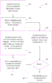
Fig. 2 is a block diagram of a process for forming a chemical delivery device.
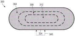
Fig. 3A is a plan view of chambers formed in one layer of a chemical delivery device, where each chamber can receive an active chemical.
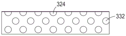
Fig. 3B is a first cross-sectional view of the chemical delivery device of fig. 3A.
Fig. 3C is a second cross-sectional view of the chemical delivery device of fig. 3A.
Fig. 4 is an illustration of a density profile of halftone image data corresponding to a distribution of active chemical within a chemical delivery device.
Fig. 5 is a graph depicting the respective arrangement of image data for two different active chemicals in a sample of a halftone screen and a region of a matrix of a chemical delivery device.
Detailed Description
For a general understanding of the environment of the devices disclosed herein and the details of the devices, reference is made to the accompanying drawings. In the drawings, like numbering represents like elements.
As used herein, the term "halftone screen" refers to a two-dimensional or three-dimensional arrangement of digital thresholds used to control the distribution of material to form a three-dimensional printed object, such as a chemical delivery device. Each entry in the halftone screen is referred to herein as a "dot". The dots are arranged in two-dimensional space for a two-dimensional halftone screen or in three-dimensional space for a three-dimensional halftone screen. The term "dot center" refers to a single dot that serves as the center location of a group of multiple dots, each dot being assigned a threshold based on the value of the dot center. For example, in some embodiments, the controller generates a particular threshold at the center of the point and "grows" the set of points around the center of the point by the same threshold. In other configurations, the center of the spot corresponding to the cavity that is a candidate for receiving the active chemical is surrounded by a "guard" spot having a fixed value corresponding to the adjuvant that encapsulates the cavity. The dot centers correspond to locations in the halftone screen and final image data that optionally receive active chemical based on the concentration parameter of the active chemical and a threshold value for the dot centers. The surrounding points each correspond to a location that receives the adjuvant and does not receive the active material to ensure that the active material is encapsulated within the chemical delivery device.
As described in more detail below, printers use a halftone screen in conjunction with concentration parameter data for one or more active chemicals to generate "halftone image data" or, more simply, "image data. The image data includes a two-dimensional or three-dimensional arrangement of locations specifying the type of material in the chemical delivery device, where each location in the image data is referred to herein as a "pixel. Each pixel in the image data corresponds to the position of one dot in the halftone screen. However, the pixels in the image data each include values that specify one type of adjuvant or active material that the printer discharges to form a chemical delivery device having a concentration level of active chemical corresponding to the concentration parameter, without including threshold values for dots in the halftone screen. The term pixel as used herein also includes the general meaning of the term "voxel" (volumetric pixel), which refers to the three-dimensional volumetric unit of shape and structure that forms a model of a three-dimensional printed object. The three-dimensional object printer uses image data to control the operation of the jet or other material dispenser to form a structure and distribute the active chemical in the chemical delivery device.
As used herein, the term "random halftone screen" refers to a halftone screen in which dot centers are uniformly sized and pseudo-randomly distributed throughout a two-dimensional or three-dimensional space. Conventional fixed frequency halftone screens typically establish a collection of dot centers at a fixed point based on a crystal lattice. Common halftone screens may place dot centers at the vertices of a square or hexagonal grid in two dimensions (or at the vertices of cubes or at the centers of closely packed spheres in three dimensions). Fixed frequency halftone screens increase the number of "on" dots by adding additional dots near the center of the existing dots. The random screen increases the number of points corresponding to a particular threshold or range of thresholds by increasing additional point centers that are not generally adjacent to previous point centers.
As used herein, the term "vector halftone screen" refers to a type of halftone screen in which a single halftone screen positions multiple types of active chemicals at different locations to prevent mixing of different active chemicals during the manufacturing process of a chemical delivery device. Vector halftone screening differs from many prior art halftone screens associated with printed images in that each color (e.g., cyan, magenta, yellow, black) in a multicolor printer has a separate halftone screen, and the printer generates separate image data sets for each color, which are commonly referred to as "separations. In conventional printing, many printed images include halftone image data that prints two color inks in a plurality of color separations at the same physical location on a sheet of paper that is part of the printed image, which is sometimes desirable when printing color images. However, in many chemical delivery device embodiments, different active chemicals like different colored inks should not be printed at a single physical location, as the active chemicals should only mix when released from the chemical delivery device. In contrast, vector halftone screens enable the formation of chemical delivery devices that use multiple active chemicals using a single halftone screen that prevents multiple active chemicals from printing to a single location.
Using a vector halftone screen, the controller assigns different threshold ranges to different active chemicals based on the concentration parameter value for each active chemical. The threshold ranges do not overlap so that each dot center within the vector halftone can be assigned to at most one type of active chemical or to an adjunct for a dot that does not correspond to any active chemical. At each point location in the halftone screen, the controller identifies a threshold in the halftone screen and generates pixels of image data corresponding to at most one active chemical based on a "stacked" threshold level of the one or more active chemicals. For halftone dots having a threshold value that does not correspond to a range of any active chemical, the controller generates image data pixels corresponding to the supplemental material filling the pixels.
As described in more detail below in connection with FIG. 5, a practical embodiment of a halftone screen includes dots having thresholds (0-255) in an 8-bit value range. The controller receives the concentration parameters, optionally as percentage values, and assigns a non-overlapping or "stacked" portion of the 8-digit numerical range to each concentration parameter based on the size of the concentration parameter (e.g., 25% for chemical A → 0-63; 16% for chemical B → 64-104; and the adjunct usage remaining value 105 → 255). By assigning each dot to one chemical (e.g., dot value of 24 → image data pixel of chemical a; dot value of 134 → image data pixel of the auxiliary material) based on the dot value and the numerical range of each chemical, the controller uses the dot values of the vector halftone screen at the different locations to determine which compound to print for each respective pixel in the image data. The statistical distribution of the thresholds within the vector halftone screen ensures that the multiple chemicals are evenly distributed within each region of the chemical delivery device. Thus, the vector halftone screen and corresponding halftone processing enable the generation of image data corresponding to the distribution of one or more active chemicals that prevents mixing of the active chemicals during the process of producing the chemical delivery device.
As used herein, the terms "random halftone screen" and "vector halftone screen" do not refer to the mutually exclusive properties of halftone screens. Rather, a single halftone screen may have both the random and vector properties described above that form a random vector halftone screen. For example, in chemical delivery devices that use only a single active chemical, a stochastic halftone screen enables the production of chemical delivery devices by dispensing the single active chemical in different regions of the chemical delivery device based on the concentration parameters of the single active chemical in each region. Although the halftone screen is optionally a vector halftone screen in a single chemical configuration, the vector nature is not required as there is only a single active chemical. In the production of chemical delivery devices that include two or more active chemicals, printers use random vector halftone screens for halftone processing to control the distribution of the two or more active chemicals within the chemical delivery device.
As used herein, the term "process direction" refers to the direction of movement of the support member past the one or more print heads during the three-dimensional object forming process. The support member holds the three-dimensional object during the printing process. In some embodiments, the support member is a planar member, such as a metal plate, while in other embodiments, the support member is a rotating cylindrical member or a member having another shape that supports the formation of the object during the three-dimensional object printing process. In some embodiments, the print head remains stationary while the support member and the object move past the print head. In other embodiments, the printhead moves while the support member remains stationary. In still other embodiments, both the printhead and the support member move.
As used herein, the term "cross process direction" refers to a direction perpendicular to the process direction and in the plane of the support member. The ejectors in two or more print heads are aligned in a cross process direction to enable an array of print heads to form a printed pattern of the secondary material or active chemical material on a two-dimensional planar area. During the three-dimensional object printing process, the print head ejects drops of the auxiliary material to form successive layers of structures and cavities within the chemical delivery device.
As used herein, the term "z-axis" refers to an axis perpendicular to the process direction, the cross-process direction, and the plane of the support member in the three-dimensional object printer. At the beginning of the three-dimensional object printing process, separation along the z-axis refers to the separation distance between the support member and the print head that forms the layer of the auxiliary material in the three-dimensional printing chemical delivery device. As the ejectors in the print head form each layer of the secondary material, the printer adjusts the z-axis separation between the print head and the uppermost layer to maintain a substantially constant distance between the print head and the uppermost layer of the object during the printing operation. In some embodiments, the support member moves away from the print head during a printing operation to maintain z-axis separation, while in other embodiments, the print head moves away from the portion of the print object and the support member to maintain z-axis separation.
Fig. 1 depicts an additive manufacturing device embodied as a three-dimensional object printer 100 or a simpler printer 100. Printer 100 is configured to operate a printhead to form a three-dimensional printing chemical delivery device 300 that includes one or more active chemicals encapsulated within a structure formed from at least one type of adjuvant. Printer 100 includes a support member 102, printhead arrays 104A-104C, 108A-108C, and 112A-112C, an Ultraviolet (UV) curing device 116, a controller 128, a memory 132, and a planarizer 118. In the exemplary embodiment of fig. 1, the three-dimensional object printer 100 is depicted during formation of a three-dimensional chemical delivery device 300 formed from multiple layers of a secondary material. Chemical device 300 includes multiple layers of chambers that receive active chemicals in the form of chemical carrier drops that are ejected into portions of the chambers by one or more ejectors in printhead arrays 104A-104C and 108A-108C with reference to concentration parameters in different regions of chemical delivery device 300.
In the embodiment of fig. 1, the support member 102 is a planar member, such as a metal plate, that moves in the process direction P. Printhead arrays 104A-104C, 108A-108C, and 112A-112C, UV curing device 116, and flattener 118 form print zone 110. The member 102 carries any previously formed layers of supplemental material and cavities that have been filled with active chemical material in the process direction P through the print area 110. During a printing operation, the support member 102 moves in a predetermined process direction path that passes the print head multiple times to form successive layers of the auxiliary material and the active chemical in the chemical delivery device 300. In some embodiments, a plurality of members similar to member 102 pass through print zone 110 in a carousel or similar configuration. One or more actuators move the member 102 in the process direction P through the print zone 110. In the embodiment of fig. 1, after each layer of the minor material is applied to the support member 102 to form the chemical delivery device 300, the actuator also moves the support member 102 in the direction Z away from the components in the print zone 110. The actuator moves the support member 102 in the direction Z to maintain uniform separation between the uppermost layer of the chemical delivery device 300 and the components in the print zone 110.
Each printhead in the printhead arrays 104A-104C, 108A-108C, and 112A-112C includes at least one ejector. In the exemplary printhead embodiment of FIG. 1, each printhead includes a two-dimensional array of ejectors that eject drops using, for example, piezoelectric or thermal transducers. In many practical embodiments, each printhead includes an ejector array having a density that enables printing of hundreds or thousands of material drops per linear inch (DPI). The printer 100 shown in fig. 1 ejects drops of two different types of active chemicals with printhead arrays 104A-104C configured to eject drops of a first active chemical and printhead arrays 108A-108C configured to eject drops of a second active chemical. Printhead arrays 112A-112C eject drops of an adjuvant (e.g., a polymeric material) that form the structure of chemical delivery device 300, including a chamber within chemical delivery device 300 that receives an active chemical.
In many embodiments, the active chemical is dissolved or suspended in a chemical carrier for ejection as droplets through inkjets in the printheads 104A-104C and 108A-108C. In some configurations, the chemical carrier evaporates within the cavities of the chemical delivery device 300 prior to sealing each cavity to leave the active chemical in the cavity, while in other embodiments, the chemical carrier remains in a liquid state within the cavity. Although the precise formulation of the chemical carrier may vary for different types of chemical delivery devices, the chemical carrier is typically a liquid form of the adjuvant. That is, the chemical carrier does not interact with the active chemical or significantly alter the nature of the chemical reaction when the chemical delivery device dissolves and discharges the active chemical. Of course, some active chemicals are already available in liquid form compatible with the printheads and ejectors in printer 100. In these configurations, the chemical carrier and the active chemical are the same material.
Although each of the printhead arrays 104A-104C, 108A-108C, and 112A-112C are depicted as including three printheads, alternative configurations may include fewer printheads or a greater number of printheads to accommodate print zones having different sizes in the cross-process direction. Alternative embodiments of printer 100 include a greater or lesser number of printhead arrays to handle different combinations of active chemicals. While printhead arrays 104A-104C, 108A-108C, and 112A-112C remain stationary during operation in printer 100, alternative printer embodiments include one or more printheads that move in a cross process direction CP, a process direction P, or both a cross process direction and a process direction. The moving print head forms the structure of the three-dimensional chemical delivery device and deposits the active chemical within the chemical delivery device. Additionally, although fig. 1 depicts a single chemical delivery device 300 for exemplary purposes, in many practical embodiments, using the printhead array shown in fig. 1, printer 100 simultaneously forms multiple chemical delivery devices, e.g., a sheet of supplemental material containing multiple tablets that can be swallowed by an average person. After operation of the printer 100 is complete, the larger sheet of the auxiliary material is then mechanically separated into individual chemical delivery devices.
In the embodiment of printer 100 shown in FIG. 1, printheads 112A-112C serve as dispensers for auxiliary materials. In an alternative configuration of the print zone 110, the supplemental material powder dispenser includes a spreader (not shown) that discharges supplemental material as a thin layer of powder covering the upper surface of the chemical delivery device 300. The powder dispenser is positioned across print zone 110 in a similar configuration as UV curing device 116. Ejectors in the print heads 112A-112C eject drops of liquid binder material onto selected locations of each powder layer to bind and harden the powder into a durable portion of the chemical delivery device. The UV curing device 116 in some embodiments optionally cures the adhesive. Excess powder that does not receive a binder is removed from chemical delivery device 300 to expose cavities that receive chemical carriers including active chemicals from printhead arrays 104A-104C and 108A-108C.
In printer 100, UV curing device 116 is an ultraviolet light source that generates UV light across print area 110 in cross process direction CP. The UV light from the UV curing device 116 hardens the auxiliary material on the uppermost layer of the chemical delivery device 300 to form a durable portion of the chemical delivery device 300. The UV curing process solidifies the additive to accept additional layers of additive and form an array of cavities, which may contain a liquid chemical carrier with active chemicals ejected from ejectors in one or more printhead arrays (e.g., arrays 104A-104C and 108A-108C).
As used herein, the term "flattener" refers to a member configured to engage the uppermost surface of each layer of the adjuvant in the chemical delivery device prior to the UV curing device 116 curing the adjuvant. In the printer 100, a screed 118 (also referred to as a planarizer) applies pressure and optionally heat to smooth the uppermost layer of the minor material in the chemical delivery device 300 and form a uniform surface that receives additional layers of minor material during subsequent passes through the print area 110. In some embodiments, the screed 118 is a roller coated with a low surface energy material to prevent the auxiliary material in the chemical delivery device 300 from adhering to the surface of the screed 118. While other components in the print zone 110 remain a predetermined distance from the chemical delivery device 300 in the Z-direction, the screed 118 engages the chemical delivery device 300 during at least some passage through the print zone 110 to smooth the uppermost layer of the minor material.
Fig. 2 depicts a process 200 for forming a chemical delivery device having a range of concentration levels of one or more active chemicals in a matrix formed with one or more forms of an adjuvant. In the following discussion, reference to process 200 performing an action or function refers to operating a controller in an additive manufacturing device (e.g., a three-dimensional object printer) to execute stored program instructions to perform the function or action associated with a component in the additive manufacturing device. Process 200 is described in conjunction with the three-dimensional object printer of fig. 1 for exemplary purposes.
During process 200, printer 100 optionally forms a substrate layer in a chemical delivery device from a substrate material having a plurality of exposed cavities that may be used to receive active chemicals from printer 100 during process 200 (block 204). In one embodiment, the printer 100 forms the substrate from the powdered additive using a dispenser that supplements the printheads 112A-112C. The controller 128 operates the ejectors in a group of printheads (e.g., printheads 112A-112C) to eject the binder material in a predetermined pattern to form a hardened layer of the auxiliary material. The controller 128 operates the ejectors in the printheads 112A-112C based on the chemical delivery device structure data 138 to form each layer of the chemical delivery device 300 having a predetermined structure and chamber arrangement. The controller 128 also forms a cavity in the substrate at a location that does not receive binder material, wherein excess powder that does not receive binder is removed after the printer 100 forms a layer of the cavity. The printer 100 typically forms each set of cavities from multiple layers of the secondary material forming the floor and sidewalls of each cavity.
In another embodiment, one or more print head arrays in printer 100 eject drops of the auxiliary material that harden to form the matrix and cavities from multiple layers of the auxiliary material using, for example, a UV curable polymer or other suitable auxiliary material. Controller 128 uses chemical delivery device configuration data 138 to control ejection of drops of auxiliary material from printheads 112A-112C to form layers of chemical delivery devices having a predetermined shape and arrangement of cavities. In yet another embodiment, devices other than printer 100 form the substrate and the chamber. The printer 100 receives a substrate having an exposed cavity on a support member 102.
Fig. 3A-3C depict an example of a chemical delivery device 300 having multiple layers of a cavity. Fig. 3A depicts a plan view of a substrate in chemical delivery device 300 having an array of cavities (e.g., cavities 324) formed in one layer of chemical delivery device 300. In the example of fig. 3, printer 100 is configured to generate halftone image data of the active chemical injected into a portion of the chamber shown in fig. 3A. In the exemplary embodiment of fig. 3A, the printer 100 receives different density parameters for three different regions 304, 308, and 312 in the exposure layer. While fig. 3A depicts region 304-312 in one layer of chemical delivery device 300, in many embodiments the region extends through a cavity formed in multiple layers of chemical delivery device 300 to form a three-dimensional region. Furthermore, although fig. 3A depicts three regions 304-312 for exemplary purposes, alternative configurations may include a different number of regions and also include gradients of varying concentration parameters across the chemical delivery device 300.
Fig. 3B and 3C depict cross-sectional views of a portion of chemical delivery device 300 taken along line 340. Fig. 3B depicts one layer of an exposed chamber including chamber 324, wherein the exposed chamber is approximately hemispherical in shape to receive a drop of liquid chemical carrier and active chemical. The chemical delivery device includes multiple layers of cavities including a three-dimensional arrangement of cavities 332. Fig. 3C depicts another configuration in which the auxiliary material forms an upper layer including cavities 324 such that it is almost completely formed with openings at the top of each exposed cavity that are large enough to enable the chemical carrier and active chemical to enter and substantially fill the cavity. The auxiliary material in chemical delivery device 300 seals the lower layer of the cavity. In some embodiments, printer 100 moves support member 102 and chemical delivery device 300 multiple times through print area 110 to form the structure of chemical delivery device 300 from a complementary material that provides a structure having multiple layers of cavities. The printer 100 ejects drops of active chemical to fill selected portions of the exposed cavities in each layer of the chemical delivery device 300. Operating the printer 100 to generate halftone image data for different areas of the chemical delivery device 300 and ejecting a chemical carrier comprising one or more active chemicals into different sets of chambers using a stochastic halftone screen or a vector halftone screen is presented in further detail below.
The excipients forming the structure of chemical delivery device 300 isolate each lumen from each other to prevent fluid communication between the lumens. In particular, the adjunct prevents the formation of fluid channels between the lumens, which may enable greater than expected release of the active chemical when the adjunct dissolves to expose the fluidly coupled lumens. Additionally, in chemical delivery devices that include two or more active chemicals, the isolated cavities prevent the active chemicals from combining before the adjuvant is dissolved in the chemical delivery device 300. Although fig. 3B and 3C depict spherical cavities, chemical delivery device 300 may include cavities having different sizes and shapes, including oblate spherical and cylindrical cavities for different types of chemical delivery devices.
As shown in fig. 3A, the chemical delivery device 300 includes a plurality of regions 304 and 312, and the printer 100 processes the concentration parameter data in the plurality of regions of the substrate to generate halftone image data capable of delivering different densities of active chemical to the cavities within each region. For example, in one chemical delivery device configuration, the concentration parameter increases from the outermost region 304 through the middle region 308 to the innermost region 312. As the volume of each zone decreases from the outer zone 304 to the central zone 312, appropriate selection of concentration levels enables the chemical delivery device 300 to discharge active chemical at a substantially constant rate as the chemical delivery device 300 dissolves. Of course, in alternative configurations, the concentration parameter may affect the discharge rate of the active chemical in a variety of ways, including a gradient that enables chemical delivery device 300 to discharge one or more active chemicals at varying rates over time as chemical delivery device 300 dissolves.
Although the chemical delivery device 300 is formed with a cylindrical center, typically two hemispheres at each end of a cylinder of a shape associated with drug tablets and other chemical tablets, the printer 100 is configured to form a wide variety of shapes and sizes of substrates having a chemical delivery device and individual cavities. Chemical delivery device 300 is merely an exemplary embodiment of a three-dimensional device having multiple layers with cavities to receive various concentrations of active chemicals.
Referring again to fig. 2, process 200 continues with printer 100 receiving concentration parameter data specifying concentration levels of one or more active chemicals in one or more regions of a chemical delivery device (block 208). The concentration parameter includes a value specifying a proportion of the cavities in a given region of the chemical delivery device that receive the corresponding active chemical. In the printer 100, the controller 128 receives the stored density parameter data 140 from the memory 132. The concentration parameters correspond to one or more active chemicals within at least one region of chemical delivery device 300. In one embodiment, the concentration parameter for each active chemical is specified as a percentage in the range of 0% to 100%, where 0% indicates that no active chemical is present in a particular region of the chemical delivery device, 100% indicates that all available cavities in that region are to receive active chemical, and the middle percentage corresponds to the specific number of cavities in that region that receive chemical in that region. Some chemical delivery devices include a region having concentration parameters for two or more active chemicals. The sum of the concentration parameters does not exceed 100% or some other predetermined maximum parameter value to ensure that the matrix has sufficient lumen locations for all active chemicals in the region of the chemical delivery device.
Fig. 4 depicts a graph 400 of concentration parameters for two different active chemicals (chemical a and chemical B) in different regions of a chemical delivery device. In fig. 4, a total of forty regions in a three-dimensional cylindrical volume approximates the shape of a chemical delivery device, such as device 300 of fig. 3. Each region corresponds to a three-dimensional concentric shell starting from a region (x-index 1) around the center of the cylinder and extending to the outside of the cylinder (x-index 40). The example of fig. 4 depicts a concentration gradient for two different reactive chemicals. As used herein, the term "concentration gradient" refers to a variation in the concentration level of the active chemical dispensed in different regions of the chemical delivery device produced by the printer 100 based on multiple concentration parameters of multiple regions in the chemical delivery device. The different concentration gradients enable differently configured chemical delivery devices to discharge active chemical at a substantially constant rate, at an increasing or decreasing rate, or even an oscillating rate as the chemical device dissolves.
In the example of fig. 4, the concentration gradient of first active chemical a specifies a decreasing concentration from the center of the chemical delivery device outward toward the exterior of the device, while the concentration gradient of second active chemical B specifies an increasing concentration from the center of the chemical delivery device outward toward the exterior of the device. The alternative concentration gradient includes a plurality of concentration parameters that form a non-linear and non-monotonic change in concentration through different regions of the chemical delivery device. Although fig. 4 depicts a concentration gradient over a three-dimensional region in a chemical delivery device having an approximately cylindrical shape, similar concentrationsThe gradient may also be applied to chemical delivery devices having a wide range of shapes. Another approximation of the chemical delivery device 300 of fig. 3A models the volume of the chemical delivery device as a cylinder with two spheres: v ═ 4 π r2+2 π r |) r. Similar approximations of the three-dimensional geometries of various chemical delivery devices are known to those of ordinary skill in the art.
Referring again to fig. 2, the process 200 continues with the controller 128 in the printer 100 generating halftone image data using a random halftone screen (which may also be a vector halftone screen if multiple compounds are being printed) with reference to one or more density parameters in each region of the image data corresponding to the substrate (block 212). The controller 128 generates pixels of the image data using threshold values for corresponding points in the halftone screen and threshold ranges for the active chemicals and the adjunct based on the concentration parameters of the one or more active chemicals. As used herein, the term "activated pixel" refers to a pixel location in the halftone image data that receives the active chemical, while the remaining pixels that form the structure of the chemical delivery device receive the inactive material or adjuvant. In an embodiment of the process 200 of forming a chemical delivery device with two or more active chemicals, the controller 128 generates image data with only one active chemical at any given pixel location of the image data using a vector halftone screen. As described in more detail below, the printer 100 also ejects drops of the auxiliary material for the remaining pixels that are inactive pixels. The halftone image data includes a plurality of activated pixels corresponding to locations of only a portion of a plurality of cavities formed in the substrate that receive the active chemical. In some configurations, a region receives one active chemical, while in other configurations, a single region receives two or more active chemicals. As described above, the random vector halftone screen includes an arrangement of dots having a threshold that produces halftone image data having a pixel distribution corresponding to the physical arrangement of the cavities in the chemical delivery device.
The halftone processing generates halftone image data having a predetermined arrangement of pixels corresponding to locations of cavities exposed in a substrate of the chemical delivery device. If the chemical being dispensed does not have the same dissolution rate as the adjuvant in the target solvent, or if multiple chemicals are included that cannot be contacted, the halftone screen also includes "guard" dots having a predetermined threshold or range of values that surround the dots corresponding to the different chambers in the chemical delivery device. The protection points have a fixed value that never corresponds to the active chemical. The printer 100 generates halftone image data based on the guard dots, which include respective "guard" pixels surrounding the locations of the cavities and corresponding to the locations of walls and other structures in the matrix that do not receive a drop of the active chemical. In fig. 5, the halftone screen includes an arrangement of guard dots corresponding to the arrangement of cavities in one layer of the chemical delivery device 300. Guard points are assigned a predetermined value or range of values (e.g., 255 in the example of fig. 5) that ensure that they are only used for printing aids and not any active chemicals.
To generate the halftone screen, the controller 128 uses predetermined halftone screen data stored in the halftone screen data 142 of the memory 132, or the controller 128 generates a pseudo-random number value threshold for each dot corresponding to a cavity and being a candidate for receiving an active chemical. Only a portion of the chambers in each zone receive active chemical except where the zones of the chemical delivery device are saturated to 100% concentration. The remaining cavities remain empty or the printer 100 fills the cavities with an adjuvant or inactive material (such as water, glycerin, triglycerides, or another liquid) that forms the chemical delivery device 300. The filler material depends on the chemistry of the environment in which the chemical device is dissolved. In some embodiments, when the sprayer in the printer sprays the chemical carrier without any dissolved active chemical, the chemical carrier that holds the active chemical in solution is also used as the inactive liquid. The controller 128 uses the thresholding process described below to identify the portions of the pixels that receive different active chemicals based on the halftone screen values and threshold ranges.
Fig. 5 depicts a single layer two-dimensional halftone screen 500 corresponding to one area of a chemical delivery device used by printer 100 during process 200. Halftone screen 500 is an illustrative example of a random vector halftone screen suitable for use in producing a chemical delivery device containing one or more active chemicals. In the printer 100, the memory 132 stores the halftone screen 500 and optionally stores additional two-dimensional or three-dimensional halftone screens having halftone screen data 142. Fig. 5 also depicts a table 550 showing concentration parameters for two different reactive chemicals distributed in halftone image data. The halftone screen data 500 is encoded in an 8-bit value range with each dot taking on a value of 0 to 255, but in alternative configurations, other embodiments use a different range and the guard points may be assigned a different value, e.g., 0. In fig. 5, the dots having a value of 255 are each guard dots corresponding to the location of a wall or feature in the matrix of the chemical delivery device other than the cavity, and the printer 100 does not eject drops of the active chemical to the location corresponding to the guard dots. Fig. 5 depicts a single set of guard points around each potential location of the active chemical, but alternative embodiments use different numbers of guard points based on the size and arrangement of the cavities in the matrix. Some embodiments omit the point of protection if the particular chemical delivery device does not require a separate active chemical location. Additionally, although halftone screen 500 depicts a single dot for each cavity, different halftone screen embodiments include dot arrangements for cavities of different sizes and shapes.
Although fig. 5 depicts a two-dimensional halftone screen 500 corresponding to a single layer area of a larger three-dimensional chemical delivery device, in printer 100 halftone screen data 142 typically includes a three-dimensional halftone screen that includes multiple layers to define a three-dimensional area of chemical delivery devices on multiple layers. Some layers of the halftone screen may include only protective dots corresponding to the minor ingredients to enable the printer 100 to form a protective layer of minor ingredients over previously filled cavities in the chemical delivery device. In the three-dimensional halftone screen embodiment, halftone screen 500 represents one layer of a multi-layer halftone screen. During operation, the printer 100 forms each layer of the chemical delivery device using a selected one of the two-dimensional halftone screen portions of the larger three-dimensional halftone screen for each layer.
In one embodiment, the halftone screens are stored in the memory 132 prior to the printing process. As described below, the printer lays down a single halftone screen in an iterative process to cover the three-dimensional area occupied by the chemical delivery devices for a wide range of chemical device shapes and sizes to enable a smaller halftone screen to be used to form image data in one or more areas of a larger chemical delivery device. The controller 128 adjusts the threshold range for receiving active chemicals based on the concentration parameter data to enable the printer 100 to use a single halftone screen to generate image data and printing chemical delivery devices having different chemical concentration gradients for one or more active chemicals in different regions of the chemical delivery device. In another embodiment, the controller 128 generates the halftone screen threshold during the printing process. The controller 128 generates the values at the center of the point on the screen in a pseudo-random manner to produce a more uniform distribution than would be obtained using a completely random number. For example, using a pseudo-random process, the controller 128 generates a threshold value for the dot where the probability of adjacent cavities having similar halftone levels (which increases the likelihood that adjacent cavities receive the same active chemical) is less than would be expected from a purely random process. In embodiments using a guard point, the controller 128 uses only a pseudo-random process to generate a threshold value for the center of the point aligned with the cavity in the chemical delivery device and the guard point (e.g., the point value of 255 in fig. 5) remains at a fixed value.
During process 200, the controller 128 generates activated pixels of one or more active chemicals in the portion of the halftone image data based on the concentration parameters of each active chemical within the region and based on the threshold values in the halftone screen assigned to the dot locations of each cavity within the region. As shown in table 550, the concentration parameter for the first active chemical (chemical a) is 32%, and the controller 128 generates a threshold range of 0 to 81 (e.g., about 32% of the 256 available values) using the predetermined scale of 0-255 of fig. 5. Thus, the controller generates an activated pixel in the halftone image data assigned to the first active chemical that corresponds to the location of a point in halftone screen 500 having a value of 0-81. The table 550 includes another concentration parameter of 23% of the second active chemical (chemical B) and the controller 128 generates a second range of values for 82-140 of the second active chemical (e.g., about 23% of 256 values with a shift of +82 to avoid overlapping the threshold range of the first chemical). The numerical ranges of the first and second active chemicals are "stacked," meaning that the numerical ranges do not overlap to ensure that the controller 128 selects at most one active chemical for any candidate point in the halftone screen in the image data 500 (e.g., a point without a guard value of 255). The remaining dots corresponding to the cavities in the matrix having a numerical dot threshold of 141 to 255 do not receive either of the first or second active chemicals, and the controller 128 classifies these pixels as "inactive" in fig. 5, indicating that the adjuvant or another inactive material will fill the cavities that do not receive the active chemical.
For example, halftone screen data 500 includes dots 504 having a numerical threshold of 22. The controller 128 generates activated pixels of the first active chemical in the halftone image data based on the concentration parameter based on a threshold value and a threshold range of the first active chemical. Similarly, the controller 128 generates an activated pixel of the second active chemical corresponding to the point 508 having the numerical threshold 101. The controller 128 does not generate an activated pixel corresponding to point 512 having a value of 175 because point 512 does not belong to the threshold of any active chemical. Rather, the controller 128 generates pixels that are assigned to the adjunct or another inactive material to fill cavities that do not receive active chemicals. Similarly, the controller generates image data pixels corresponding to the auxiliary material for all guard points having a value of 255.
In a multi-layer chemical delivery device, the printer 100 optionally generates or uses a predefined three-dimensional halftone screen corresponding to the three-dimensional arrangement of cavities in multiple layers of the chemical delivery device. The three-dimensional halftone screen includes dot positions and guard dots that are candidates to receive the active material in a configuration similar to the two-dimensional arrangement of dots shown in fig. 5. The three-dimensional halftone screen includes a plurality of planes of dots similar to the planar screen 500 of fig. 5, which correspond to different layers of a chamber in a chemical delivery device. If the three-dimensional halftone screen is smaller than the object to be printed, the controller 128 tiles multiple copies of the halftone screen using a blank fill tiling process to create a larger screen that completely encloses the three-dimensional volume of the chemical delivery device. During operation, printer 100 ejects drops of one or more active chemicals against individual layers of a two-dimensional arrangement having cavities with openings that are exposed to printheads (e.g., printheads 104A-104C and 108A-108C in printer 100). Thus, while the printer 100 in some embodiments generates three-dimensional halftone image data, the printer 100 ejects active material into separate layers of chambers in a chemical delivery device that are each arranged in a two-dimensional layer.
In an alternative embodiment, the controller 128 also divides the area in the three-dimensional chemical delivery device into a series of two-dimensional areas corresponding to each layer of the cavity formed in the chemical delivery device. Based on the concentration parameters and gradients through the two-dimensional layers, the controller 128 generates or loads the halftone screen from the memory 132 as a two-dimensional arrangement of dots for each layer of the chamber in the chemical delivery device. Any embodiment of process 200 enables printer 100 to form a chemical delivery device with a varying distribution of one or more active chemicals.
Referring again to fig. 2, the process 200 continues with the printer operating at least one sprayer to spray a predetermined amount of active chemical into each of the portions of cavities in the substrate corresponding to one of the activated pixels with reference to the halftone image data (block 216). Using printer 100 as an example, controller 128 operates the ejectors in printhead arrays 104A-104C to fill each of the first portion of the cavities corresponding to the location of an activated pixel of the first active chemical in the halftone image data. Ejectors in the print heads 104A-104C eject predetermined amounts of chemical carrier and first active chemical into each chamber corresponding to an activated pixel in the image data to ensure that each region of the chemical delivery device has a concentration of active chemical corresponding to the concentration parameter. In printer 100, controller 128 operates ejectors in printheads 108A-108C to eject a predetermined amount of chemical carrier including a second active chemical into a second portion of the chamber corresponding to an activated pixel of the second active chemical, similar to the operation of printheads 104A-104C. Using fig. 3A and 5 as an example, each activation pixel in the image data generated by controller 128 using halftone screen 500 is aligned with one of the exposed layers of cavities in one region (e.g., region 304) of chemical delivery device 300. Ejectors in print heads 104A-104C and 108A-108C eject predetermined amounts of chemical carrier and active chemical into the cavities corresponding to the first and second active chemicals, respectively, to form each region of the layer in chemical delivery device 300 with the appropriate concentration of active chemical.
The process 200 continues as described above for any additional layers in the chemical delivery device (block 220). The printer 100 applies an additional layer of the adjuvant to seal the exposed cavity in the chemical delivery device and encapsulate the active chemical in any cavity that receives the active chemical, and forms another layer of the cavity from the adjuvant to form another layer of the cavity in the chemical delivery device based on the chemical delivery device structure data 138 (block 224). In the exemplary embodiment of fig. 2, controller 128 repeats the process described in connection with block 208 and 216 for an embodiment of process 200 that generates activated pixels in halftone image data separately for each layer of the chemical delivery device. In another configuration, the process 200 repeats block 216 using previously generated halftone data (e.g., another two-dimensional arrangement of halftone data in a larger set of three-dimensional halftone data) to control the ejection of active chemical into the cavities of the next layer of the chemical delivery device. The process 200 ends when no additional layers of the chamber remain in the chemical delivery device (block 220) and the printer 100 seals the last layer of the chamber with the auxiliary material (block 228).
Printer 100 and process 200 enable additive manufacturing production of chemical delivery devices that release one or more active chemicals at varying rates and contain multiple types of active chemical materials with chemical isolation between active chemicals (until the chemical delivery device dissolves). The systems and methods described herein enable the production of chemical delivery devices having different shapes and sizes with minimal reconfiguration of the three-dimensional object printer 100. In addition, the printer 100 may adjust the distribution of active chemicals throughout the structure of the chemical delivery device simply by using different sets of concentration parameters or by using alternate halftone screens to produce chemical delivery devices with different operating characteristics.
It will be appreciated that variations of the above-disclosed and other features and functions, or alternatives thereof, may be desirably combined into many other different systems, applications, or methods. Also that various presently unforeseen or unanticipated alternatives, modifications, variations or improvements therein may be subsequently made by those skilled in the art which are also intended to be encompassed by the following claims.
Claims (5)
1. A three-dimensional object printer, comprising:
a support member;
at least a first sprayer configured to spray a first chemical carrier including a first active chemical toward the support member; and
a controller operatively connected to the at least first injector and a memory, the controller configured to:
receiving a first concentration parameter of a first active chemical in a first region of a substrate in a chemical delivery device positioned on the support member;
generating halftone image data using a random halftone screen stored in the memory and with reference to the first concentration parameter, the halftone image data including a plurality of activated pixels corresponding only to locations of a first portion of a plurality of cavities formed in a substrate that receive the first active chemical; and
operating the at least first sprayer with reference to the halftone image data to spray a predetermined amount of a first chemical carrier comprising the first active chemical into each of the first portion of the cavities in the substrate to produce a chemical delivery device having a concentration of the first active chemical corresponding to the first concentration parameter.
2. The printer of claim 1, further comprising:
a dispenser configured to discharge an adjuvant to form the matrix of the chemical delivery device; and
a controller operably connected to the dispenser and further configured to:
operating the dispenser to form the matrix from a plurality of layers of the adjunct on the support member prior to spraying a predetermined volume of the first chemical carrier comprising the first active chemical.
3. The printer of claim 2, the dispenser further comprising:
a dispenser configured to discharge a powdered auxiliary material toward the support member; and
at least a second sprayer configured to spray a liquid binder in a predetermined pattern to bond portions of the adjunct to form the matrix.
4. The printer of claim 2, the dispenser further comprising:
at least a second sprayer configured to spray droplets of the auxiliary material toward the support member in a predetermined pattern to form the substrate.
5. The printer of claim 1, the controller further configured to:
receiving a plurality of concentration parameters of a first active chemical for a plurality of regions of the chemical delivery device;
generating halftone image data for the plurality of regions of the chemical delivery device with reference to the plurality of concentration parameters using a stochastic halftone screen stored in the memory; and
operating the at least first injector to inject a predetermined amount of the first chemical carrier including the first active chemical into the first portion of the cavity in the matrix at a concentration gradient through the plurality of regions of the chemical delivery device corresponding to the plurality of concentration parameters.
Applications Claiming Priority (2)
| Application Number | Priority Date | Filing Date | Title |
|---|---|---|---|
| US15/294676 | 2016-10-14 | ||
| US15/294,676 US10150282B2 (en) | 2016-10-14 | 2016-10-14 | System and method for additive manufacture of chemical delivery devices using halftone screening |
Publications (2)
| Publication Number | Publication Date |
|---|---|
| CN107953545A CN107953545A (en) | 2018-04-24 |
| CN107953545B true CN107953545B (en) | 2020-12-22 |
Family
ID=60042987
Family Applications (1)
| Application Number | Title | Priority Date | Filing Date |
|---|---|---|---|
| CN201710898863.9A Active CN107953545B (en) | 2016-10-14 | 2017-09-28 | Systems and methods for additive manufacturing of chemical delivery devices using halftone screens |
Country Status (5)
| Country | Link |
|---|---|
| US (3) | US10150282B2 (en) |
| EP (1) | EP3308764B1 (en) |
| JP (1) | JP6842801B2 (en) |
| KR (1) | KR102271105B1 (en) |
| CN (1) | CN107953545B (en) |
Families Citing this family (1)
| Publication number | Priority date | Publication date | Assignee | Title |
|---|---|---|---|---|
| CN109664508B (en) * | 2019-01-29 | 2024-01-02 | 姚光纯 | 3D printing forming device and method for matrix arrangement of spray heads |
Citations (6)
| Publication number | Priority date | Publication date | Assignee | Title |
|---|---|---|---|---|
| US6280771B1 (en) * | 1997-02-20 | 2001-08-28 | Therics, Inc. | Dosage forms exhibiting multi-phasic release kinetics and methods of manufacture thereof |
| CN104640686A (en) * | 2012-09-05 | 2015-05-20 | 阿普雷奇亚制药公司 | Three-dimensional printing system and equipment assembly |
| WO2016057029A1 (en) * | 2014-10-08 | 2016-04-14 | Hewlett-Packard Development Company, L.P. | Generating halftone data for a three-dimensional object |
| CN105500701A (en) * | 2014-10-08 | 2016-04-20 | 施乐公司 | System and method for test pattern formation during three-dimensional object printing |
| CN105793051A (en) * | 2013-12-12 | 2016-07-20 | 科迪华公司 | Ink-based layer fabrication using halftoning to control thickness |
| CN105916666A (en) * | 2014-01-16 | 2016-08-31 | 惠普发展公司,有限责任合伙企业 | Processing three-dimensional object data of an object to be generated by an additive manufacturing process |
Family Cites Families (25)
| Publication number | Priority date | Publication date | Assignee | Title |
|---|---|---|---|---|
| US6989115B2 (en) | 1996-12-20 | 2006-01-24 | Z Corporation | Method and apparatus for prototyping a three-dimensional object |
| US6007318A (en) | 1996-12-20 | 1999-12-28 | Z Corporation | Method and apparatus for prototyping a three-dimensional object |
| JP2001515472A (en) * | 1997-02-20 | 2001-09-18 | サーリックス インコーポレイテッド | Dosage forms exhibiting multiphasic release kinetics and methods for their production |
| CA2345982A1 (en) | 1998-10-12 | 2000-04-20 | Jill K. Sherwood | Composites for tissue regeneration and methods of manufacture thereof |
| CA2463481A1 (en) | 2001-10-29 | 2003-05-22 | Therics, Inc. | Three-dimensional suspension printing of dosage forms |
| US20040106904A1 (en) * | 2002-10-07 | 2004-06-03 | Gonnelli Robert R. | Microneedle array patch |
| US7727576B2 (en) | 2004-04-16 | 2010-06-01 | Hewlett-Packard Development Company, L.P. | System and a method for producing layered oral dosage forms |
| WO2008077850A2 (en) | 2006-12-21 | 2008-07-03 | Agfa Graphics Nv | 3d-inkjet printing methods |
| US7972898B2 (en) * | 2007-09-26 | 2011-07-05 | Eastman Kodak Company | Process for making doped zinc oxide |
| US7991498B2 (en) | 2009-02-03 | 2011-08-02 | Objet Geometries Ltd. | Method and system for building painted three-dimensional objects |
| US9381154B2 (en) * | 2011-06-09 | 2016-07-05 | Xerox Corporation | Direct inkjet fabrication of drug delivery devices |
| US20130193621A1 (en) | 2012-01-26 | 2013-08-01 | Justin Daya | Systems and methods of on-demand customized medicament doses by 3d printing |
| US10702453B2 (en) | 2012-11-14 | 2020-07-07 | Xerox Corporation | Method and system for printing personalized medication |
| US9156194B2 (en) * | 2013-03-14 | 2015-10-13 | Palo Alto Research Center Incorporated | Digital 3D fabrication using multi-layered mold |
| US9643362B2 (en) | 2013-03-15 | 2017-05-09 | Microsoft Technology Licensing, Llc | Full color three-dimensional object fabrication |
| EP3082852B1 (en) | 2013-12-16 | 2020-06-17 | Massachusetts Institute of Technology | Micromolded or 3-d printed pulsatile release vaccine formulations |
| US20150201500A1 (en) | 2014-01-12 | 2015-07-16 | Zohar SHINAR | System, device, and method of three-dimensional printing |
| US20150320158A1 (en) | 2014-03-14 | 2015-11-12 | Chamber Works, Llc | Articles of jewelry containing a personalizing additive such as dna and methods of making |
| CN105023296B (en) * | 2014-08-22 | 2017-12-05 | 山东大学 | A kind of halftoning projection and model generating method towards 3D printing |
| US10306106B2 (en) * | 2014-10-29 | 2019-05-28 | Hewlett-Packard Development Company, L.P. | Three-dimensional halftoning by selecting submatrix of halftone matrix to halftone each slice or layer of object |
| US10363731B2 (en) * | 2014-12-18 | 2019-07-30 | Palo Alto Research Center Incorporated | Ejector device |
| US9787871B2 (en) * | 2015-01-29 | 2017-10-10 | Xerox Corporation | Hidden Markov model generation of multi-plane random screens |
| US9286554B1 (en) | 2015-04-01 | 2016-03-15 | Xerox Corporation | System and method for halftone printing in a three-dimensional object printer |
| US10326910B2 (en) * | 2015-04-28 | 2019-06-18 | Hewlett-Packard Development Company L.P. | Using three-dimensional threshold matrices in the production of three-dimensional objects |
| US9955041B2 (en) * | 2015-06-12 | 2018-04-24 | Xerox Corporation | System and method for tone reproduction curve color resolution enhancement in a three-dimensional object printer |
-
2016
- 2016-10-14 US US15/294,676 patent/US10150282B2/en active Active
-
2017
- 2017-09-21 JP JP2017181029A patent/JP6842801B2/en active Active
- 2017-09-22 EP EP17192745.2A patent/EP3308764B1/en active Active
- 2017-09-26 KR KR1020170123831A patent/KR102271105B1/en active IP Right Grant
- 2017-09-28 CN CN201710898863.9A patent/CN107953545B/en active Active
-
2018
- 2018-10-17 US US16/162,929 patent/US11571859B2/en active Active
-
2023
- 2023-01-31 US US18/162,578 patent/US20230173760A1/en active Pending
Patent Citations (6)
| Publication number | Priority date | Publication date | Assignee | Title |
|---|---|---|---|---|
| US6280771B1 (en) * | 1997-02-20 | 2001-08-28 | Therics, Inc. | Dosage forms exhibiting multi-phasic release kinetics and methods of manufacture thereof |
| CN104640686A (en) * | 2012-09-05 | 2015-05-20 | 阿普雷奇亚制药公司 | Three-dimensional printing system and equipment assembly |
| CN105793051A (en) * | 2013-12-12 | 2016-07-20 | 科迪华公司 | Ink-based layer fabrication using halftoning to control thickness |
| CN105916666A (en) * | 2014-01-16 | 2016-08-31 | 惠普发展公司,有限责任合伙企业 | Processing three-dimensional object data of an object to be generated by an additive manufacturing process |
| WO2016057029A1 (en) * | 2014-10-08 | 2016-04-14 | Hewlett-Packard Development Company, L.P. | Generating halftone data for a three-dimensional object |
| CN105500701A (en) * | 2014-10-08 | 2016-04-20 | 施乐公司 | System and method for test pattern formation during three-dimensional object printing |
Also Published As
| Publication number | Publication date |
|---|---|
| US10150282B2 (en) | 2018-12-11 |
| US20180104911A1 (en) | 2018-04-19 |
| KR20180041566A (en) | 2018-04-24 |
| EP3308764A1 (en) | 2018-04-18 |
| US20190047278A1 (en) | 2019-02-14 |
| EP3308764B1 (en) | 2021-12-22 |
| CN107953545A (en) | 2018-04-24 |
| KR102271105B1 (en) | 2021-06-29 |
| JP6842801B2 (en) | 2021-03-17 |
| US11571859B2 (en) | 2023-02-07 |
| US20230173760A1 (en) | 2023-06-08 |
| JP2018062171A (en) | 2018-04-19 |
Similar Documents
| Publication | Publication Date | Title |
|---|---|---|
| JP4041810B2 (en) | Method for manufacturing an object by solid freeform assembly and solid freeform assembly apparatus | |
| KR100450358B1 (en) | Method and apparatus for data manipulation and system control in a selective deposition modeling system | |
| JP4908679B2 (en) | Three-dimensional printing apparatus and method | |
| US7225045B2 (en) | System and method for three dimensional model printing | |
| IL271675A (en) | System and method for depositing liquids | |
| JPH06179243A (en) | Device, method, and process for producing three-dimensionally shaped object from computer data under computer control | |
| US20230173760A1 (en) | Chemical delivery devices produced using halftone screening in an additive manufacturing process | |
| JP6454497B2 (en) | Three-dimensional object forming apparatus and three-dimensional object forming method | |
| JP2016159536A (en) | Apparatus for three-dimensional molding, manufacturing method and computer program | |
| CN113286693B (en) | Method for producing three-dimensional molded objects by applying material layer by layer | |
| US20180043676A1 (en) | System and method for protection of printed images formed on surfaces of three-dimensional printed objects | |
| CN105965882B (en) | Three-dimensional modeling apparatus and three-dimensional object manufacturing method | |
| CN107530966A (en) | Three-dimensional body of the generation with target surface roughness | |
| US11884020B2 (en) | Print head and method of calibrating the same | |
| CN107848196B (en) | Dispensing of printing agent | |
| KR20170077795A (en) | Apparatus for applying ink and method therefor | |
| JP2016168751A (en) | Three-dimensional molding apparatus, production method, and computer program | |
| JP6952243B2 (en) | Printing method and printing equipment | |
| JP5281989B2 (en) | Pattern transfer apparatus and pattern forming method | |
| CN108656522A (en) | Stereoscopic article styling apparatus and stereoscopic article formative method | |
| KR20150080663A (en) | 3 dimentional printing and printer attached multi directional moving nozzle and baseplate | |
| RU2783433C1 (en) | Method for manufacturing a three-dimensional shaped article by additive manufacturing | |
| JP7428724B2 (en) | Method of manufacturing at least one solid layer on a base rotatable about an axis of rotation | |
| US20220234289A1 (en) | 3d printed objects and enclosed container structures | |
| JP2016165845A (en) | Three-dimensional molding apparatus, production method, and computer program |
Legal Events
| Date | Code | Title | Description |
|---|---|---|---|
| PB01 | Publication | ||
| PB01 | Publication | ||
| SE01 | Entry into force of request for substantive examination | ||
| SE01 | Entry into force of request for substantive examination | ||
| GR01 | Patent grant | ||
| GR01 | Patent grant |