CN107925010B - Barrier film construction - Google Patents
Barrier film construction Download PDFInfo
- Publication number
- CN107925010B CN107925010B CN201680048145.6A CN201680048145A CN107925010B CN 107925010 B CN107925010 B CN 107925010B CN 201680048145 A CN201680048145 A CN 201680048145A CN 107925010 B CN107925010 B CN 107925010B
- Authority
- CN
- China
- Prior art keywords
- electronic device
- organic electronic
- barrier
- barrier film
- adhesive
- Prior art date
- Legal status (The legal status is an assumption and is not a legal conclusion. Google has not performed a legal analysis and makes no representation as to the accuracy of the status listed.)
- Active
Links
- 230000004888 barrier function Effects 0.000 title claims abstract description 147
- 238000010276 construction Methods 0.000 title claims abstract description 27
- 239000000853 adhesive Substances 0.000 claims abstract description 119
- 230000001070 adhesive effect Effects 0.000 claims abstract description 119
- 229920005989 resin Polymers 0.000 claims abstract description 91
- 239000011347 resin Substances 0.000 claims abstract description 91
- 229920002367 Polyisobutene Polymers 0.000 claims abstract description 65
- 239000000203 mixture Substances 0.000 claims abstract description 58
- 239000012802 nanoclay Substances 0.000 claims abstract description 32
- 239000012790 adhesive layer Substances 0.000 claims abstract description 13
- 239000010410 layer Substances 0.000 claims description 81
- 229920000642 polymer Polymers 0.000 claims description 42
- -1 polyethylene terephthalate Polymers 0.000 claims description 40
- 239000000758 substrate Substances 0.000 claims description 29
- 230000005540 biological transmission Effects 0.000 claims description 19
- 239000004927 clay Substances 0.000 claims description 18
- 229910052760 oxygen Inorganic materials 0.000 claims description 13
- 239000001301 oxygen Substances 0.000 claims description 13
- QVGXLLKOCUKJST-UHFFFAOYSA-N atomic oxygen Chemical compound [O] QVGXLLKOCUKJST-UHFFFAOYSA-N 0.000 claims description 12
- XLYOFNOQVPJJNP-UHFFFAOYSA-N water Chemical compound O XLYOFNOQVPJJNP-UHFFFAOYSA-N 0.000 claims description 9
- 239000003208 petroleum Substances 0.000 claims description 7
- 229920000139 polyethylene terephthalate Polymers 0.000 claims description 7
- 239000005020 polyethylene terephthalate Substances 0.000 claims description 7
- GUJOJGAPFQRJSV-UHFFFAOYSA-N dialuminum;dioxosilane;oxygen(2-);hydrate Chemical compound O.[O-2].[O-2].[O-2].[Al+3].[Al+3].O=[Si]=O.O=[Si]=O.O=[Si]=O.O=[Si]=O GUJOJGAPFQRJSV-UHFFFAOYSA-N 0.000 claims description 6
- 229910000278 bentonite Inorganic materials 0.000 claims description 5
- 239000000440 bentonite Substances 0.000 claims description 5
- SVPXDRXYRYOSEX-UHFFFAOYSA-N bentoquatam Chemical compound O.O=[Si]=O.O=[Al]O[Al]=O SVPXDRXYRYOSEX-UHFFFAOYSA-N 0.000 claims description 5
- 239000011888 foil Substances 0.000 claims description 3
- 229910052901 montmorillonite Inorganic materials 0.000 claims description 3
- 125000001453 quaternary ammonium group Chemical group 0.000 claims description 3
- 239000010408 film Substances 0.000 description 122
- 238000012360 testing method Methods 0.000 description 29
- OYPRJOBELJOOCE-UHFFFAOYSA-N Calcium Chemical compound [Ca] OYPRJOBELJOOCE-UHFFFAOYSA-N 0.000 description 25
- 229910052791 calcium Inorganic materials 0.000 description 25
- 239000011575 calcium Substances 0.000 description 25
- 229920006270 hydrocarbon resin Polymers 0.000 description 21
- 230000003287 optical effect Effects 0.000 description 21
- 239000013032 Hydrocarbon resin Substances 0.000 description 20
- YXFVVABEGXRONW-UHFFFAOYSA-N Toluene Chemical compound CC1=CC=CC=C1 YXFVVABEGXRONW-UHFFFAOYSA-N 0.000 description 18
- 239000000126 substance Substances 0.000 description 18
- 239000000523 sample Substances 0.000 description 16
- 238000000576 coating method Methods 0.000 description 15
- 239000000463 material Substances 0.000 description 15
- 239000002904 solvent Substances 0.000 description 15
- IMNFDUFMRHMDMM-UHFFFAOYSA-N N-Heptane Chemical compound CCCCCCC IMNFDUFMRHMDMM-UHFFFAOYSA-N 0.000 description 14
- 239000004743 Polypropylene Substances 0.000 description 12
- 229910052751 metal Inorganic materials 0.000 description 12
- 239000002184 metal Substances 0.000 description 12
- 229920001155 polypropylene Polymers 0.000 description 12
- 239000011248 coating agent Substances 0.000 description 10
- 239000007789 gas Substances 0.000 description 10
- 238000000034 method Methods 0.000 description 9
- VQTUBCCKSQIDNK-UHFFFAOYSA-N Isobutene Chemical group CC(C)=C VQTUBCCKSQIDNK-UHFFFAOYSA-N 0.000 description 8
- 101000795655 Canis lupus familiaris Thymic stromal cotransporter homolog Proteins 0.000 description 7
- 229920005549 butyl rubber Polymers 0.000 description 7
- 238000009472 formulation Methods 0.000 description 7
- 239000011521 glass Substances 0.000 description 7
- PPBRXRYQALVLMV-UHFFFAOYSA-N Styrene Chemical compound C=CC1=CC=CC=C1 PPBRXRYQALVLMV-UHFFFAOYSA-N 0.000 description 6
- 239000000178 monomer Substances 0.000 description 6
- 230000035699 permeability Effects 0.000 description 6
- 229920005987 OPPANOL® Polymers 0.000 description 5
- 239000004698 Polyethylene Substances 0.000 description 5
- VYPSYNLAJGMNEJ-UHFFFAOYSA-N Silicium dioxide Chemical compound O=[Si]=O VYPSYNLAJGMNEJ-UHFFFAOYSA-N 0.000 description 5
- 238000001704 evaporation Methods 0.000 description 5
- 230000008020 evaporation Effects 0.000 description 5
- 239000000945 filler Substances 0.000 description 5
- 229920000573 polyethylene Polymers 0.000 description 5
- 239000007787 solid Substances 0.000 description 5
- 239000003760 tallow Substances 0.000 description 5
- 238000001771 vacuum deposition Methods 0.000 description 5
- NIXOWILDQLNWCW-UHFFFAOYSA-M Acrylate Chemical compound [O-]C(=O)C=C NIXOWILDQLNWCW-UHFFFAOYSA-M 0.000 description 4
- 229920000219 Ethylene vinyl alcohol Polymers 0.000 description 4
- RRHGJUQNOFWUDK-UHFFFAOYSA-N Isoprene Chemical compound CC(=C)C=C RRHGJUQNOFWUDK-UHFFFAOYSA-N 0.000 description 4
- 125000002723 alicyclic group Chemical group 0.000 description 4
- 239000011230 binding agent Substances 0.000 description 4
- 238000004132 cross linking Methods 0.000 description 4
- 230000009477 glass transition Effects 0.000 description 4
- 229920001519 homopolymer Polymers 0.000 description 4
- NLYAJNPCOHFWQQ-UHFFFAOYSA-N kaolin Chemical compound O.O.O=[Al]O[Si](=O)O[Si](=O)O[Al]=O NLYAJNPCOHFWQQ-UHFFFAOYSA-N 0.000 description 4
- 238000002156 mixing Methods 0.000 description 4
- 229910052814 silicon oxide Inorganic materials 0.000 description 4
- 229910021647 smectite Inorganic materials 0.000 description 4
- 238000004544 sputter deposition Methods 0.000 description 4
- UHOVQNZJYSORNB-UHFFFAOYSA-N Benzene Chemical compound C1=CC=CC=C1 UHOVQNZJYSORNB-UHFFFAOYSA-N 0.000 description 3
- 239000004952 Polyamide Substances 0.000 description 3
- 239000004642 Polyimide Substances 0.000 description 3
- DAKWPKUUDNSNPN-UHFFFAOYSA-N Trimethylolpropane triacrylate Chemical compound C=CC(=O)OCC(CC)(COC(=O)C=C)COC(=O)C=C DAKWPKUUDNSNPN-UHFFFAOYSA-N 0.000 description 3
- 229910052782 aluminium Inorganic materials 0.000 description 3
- XAGFODPZIPBFFR-UHFFFAOYSA-N aluminium Chemical compound [Al] XAGFODPZIPBFFR-UHFFFAOYSA-N 0.000 description 3
- 239000003795 chemical substances by application Substances 0.000 description 3
- 229910001919 chlorite Inorganic materials 0.000 description 3
- 229910052619 chlorite group Inorganic materials 0.000 description 3
- QBWCMBCROVPCKQ-UHFFFAOYSA-N chlorous acid Chemical compound OCl=O QBWCMBCROVPCKQ-UHFFFAOYSA-N 0.000 description 3
- 150000001875 compounds Chemical class 0.000 description 3
- 229920001577 copolymer Polymers 0.000 description 3
- 239000006185 dispersion Substances 0.000 description 3
- 150000002148 esters Chemical class 0.000 description 3
- 239000004715 ethylene vinyl alcohol Substances 0.000 description 3
- 238000011156 evaluation Methods 0.000 description 3
- 238000011065 in-situ storage Methods 0.000 description 3
- 238000005259 measurement Methods 0.000 description 3
- 239000003607 modifier Substances 0.000 description 3
- VLKZOEOYAKHREP-UHFFFAOYSA-N n-Hexane Chemical compound CCCCCC VLKZOEOYAKHREP-UHFFFAOYSA-N 0.000 description 3
- 229920003229 poly(methyl methacrylate) Polymers 0.000 description 3
- 229920002647 polyamide Polymers 0.000 description 3
- 229920000728 polyester Polymers 0.000 description 3
- 229920001721 polyimide Polymers 0.000 description 3
- 239000004926 polymethyl methacrylate Substances 0.000 description 3
- 230000001737 promoting effect Effects 0.000 description 3
- 238000000527 sonication Methods 0.000 description 3
- 229920003051 synthetic elastomer Polymers 0.000 description 3
- 239000005061 synthetic rubber Substances 0.000 description 3
- 238000012876 topography Methods 0.000 description 3
- 238000007740 vapor deposition Methods 0.000 description 3
- 229910052902 vermiculite Inorganic materials 0.000 description 3
- 239000010455 vermiculite Substances 0.000 description 3
- 235000019354 vermiculite Nutrition 0.000 description 3
- VXNZUUAINFGPBY-UHFFFAOYSA-N 1-Butene Chemical compound CCC=C VXNZUUAINFGPBY-UHFFFAOYSA-N 0.000 description 2
- HECLRDQVFMWTQS-RGOKHQFPSA-N 1755-01-7 Chemical class C1[C@H]2[C@@H]3CC=C[C@@H]3[C@@H]1C=C2 HECLRDQVFMWTQS-RGOKHQFPSA-N 0.000 description 2
- YBYIRNPNPLQARY-UHFFFAOYSA-N 1H-indene Chemical compound C1=CC=C2CC=CC2=C1 YBYIRNPNPLQARY-UHFFFAOYSA-N 0.000 description 2
- PNEYBMLMFCGWSK-UHFFFAOYSA-N Alumina Chemical class [O-2].[O-2].[O-2].[Al+3].[Al+3] PNEYBMLMFCGWSK-UHFFFAOYSA-N 0.000 description 2
- 239000005995 Aluminium silicate Substances 0.000 description 2
- KAKZBPTYRLMSJV-UHFFFAOYSA-N Butadiene Chemical compound C=CC=C KAKZBPTYRLMSJV-UHFFFAOYSA-N 0.000 description 2
- 229920000089 Cyclic olefin copolymer Polymers 0.000 description 2
- 239000004713 Cyclic olefin copolymer Substances 0.000 description 2
- 239000004593 Epoxy Substances 0.000 description 2
- YNQLUTRBYVCPMQ-UHFFFAOYSA-N Ethylbenzene Chemical compound CCC1=CC=CC=C1 YNQLUTRBYVCPMQ-UHFFFAOYSA-N 0.000 description 2
- CTQNGGLPUBDAKN-UHFFFAOYSA-N O-Xylene Chemical compound CC1=CC=CC=C1C CTQNGGLPUBDAKN-UHFFFAOYSA-N 0.000 description 2
- 229910052581 Si3N4 Inorganic materials 0.000 description 2
- GWEVSGVZZGPLCZ-UHFFFAOYSA-N Titan oxide Chemical compound O=[Ti]=O GWEVSGVZZGPLCZ-UHFFFAOYSA-N 0.000 description 2
- IAXXETNIOYFMLW-GYSYKLTISA-N [(1r,3r,4r)-4,7,7-trimethyl-3-bicyclo[2.2.1]heptanyl] 2-methylprop-2-enoate Chemical compound C1C[C@@]2(C)[C@H](OC(=O)C(=C)C)C[C@@H]1C2(C)C IAXXETNIOYFMLW-GYSYKLTISA-N 0.000 description 2
- 150000001252 acrylic acid derivatives Chemical class 0.000 description 2
- XYLMUPLGERFSHI-UHFFFAOYSA-N alpha-Methylstyrene Chemical compound CC(=C)C1=CC=CC=C1 XYLMUPLGERFSHI-UHFFFAOYSA-N 0.000 description 2
- 235000012211 aluminium silicate Nutrition 0.000 description 2
- 230000015572 biosynthetic process Effects 0.000 description 2
- 238000005229 chemical vapour deposition Methods 0.000 description 2
- 238000000151 deposition Methods 0.000 description 2
- 238000010586 diagram Methods 0.000 description 2
- 125000000118 dimethyl group Chemical group [H]C([H])([H])* 0.000 description 2
- 238000001035 drying Methods 0.000 description 2
- 230000000694 effects Effects 0.000 description 2
- 238000005538 encapsulation Methods 0.000 description 2
- 238000005516 engineering process Methods 0.000 description 2
- 230000007613 environmental effect Effects 0.000 description 2
- 125000003700 epoxy group Chemical group 0.000 description 2
- 238000005984 hydrogenation reaction Methods 0.000 description 2
- 230000006872 improvement Effects 0.000 description 2
- AMGQUBHHOARCQH-UHFFFAOYSA-N indium;oxotin Chemical compound [In].[Sn]=O AMGQUBHHOARCQH-UHFFFAOYSA-N 0.000 description 2
- 239000011229 interlayer Substances 0.000 description 2
- 229910052622 kaolinite Inorganic materials 0.000 description 2
- 150000002734 metacrylic acid derivatives Chemical class 0.000 description 2
- 229910044991 metal oxide Inorganic materials 0.000 description 2
- 150000004706 metal oxides Chemical class 0.000 description 2
- 238000012986 modification Methods 0.000 description 2
- 230000004048 modification Effects 0.000 description 2
- 150000004767 nitrides Chemical class 0.000 description 2
- TWNQGVIAIRXVLR-UHFFFAOYSA-N oxo(oxoalumanyloxy)alumane Chemical compound O=[Al]O[Al]=O TWNQGVIAIRXVLR-UHFFFAOYSA-N 0.000 description 2
- 229910052625 palygorskite Inorganic materials 0.000 description 2
- 229920000647 polyepoxide Polymers 0.000 description 2
- 239000013047 polymeric layer Substances 0.000 description 2
- 239000002952 polymeric resin Substances 0.000 description 2
- 150000003097 polyterpenes Chemical class 0.000 description 2
- 238000002360 preparation method Methods 0.000 description 2
- 238000002203 pretreatment Methods 0.000 description 2
- 230000008569 process Effects 0.000 description 2
- 229910000275 saponite Inorganic materials 0.000 description 2
- HQVNEWCFYHHQES-UHFFFAOYSA-N silicon nitride Chemical compound N12[Si]34N5[Si]62N3[Si]51N64 HQVNEWCFYHHQES-UHFFFAOYSA-N 0.000 description 2
- MSFGZHUJTJBYFA-UHFFFAOYSA-M sodium dichloroisocyanurate Chemical compound [Na+].ClN1C(=O)[N-]C(=O)N(Cl)C1=O MSFGZHUJTJBYFA-UHFFFAOYSA-M 0.000 description 2
- 239000000243 solution Substances 0.000 description 2
- 238000005507 spraying Methods 0.000 description 2
- 229920003002 synthetic resin Polymers 0.000 description 2
- 238000005979 thermal decomposition reaction Methods 0.000 description 2
- 230000008719 thickening Effects 0.000 description 2
- 239000010409 thin film Substances 0.000 description 2
- 238000002834 transmittance Methods 0.000 description 2
- 239000008096 xylene Substances 0.000 description 2
- MXFQRSUWYYSPOC-UHFFFAOYSA-N (2,2-dimethyl-3-prop-2-enoyloxypropyl) prop-2-enoate Chemical compound C=CC(=O)OCC(C)(C)COC(=O)C=C MXFQRSUWYYSPOC-UHFFFAOYSA-N 0.000 description 1
- PSGCQDPCAWOCSH-UHFFFAOYSA-N (4,7,7-trimethyl-3-bicyclo[2.2.1]heptanyl) prop-2-enoate Chemical compound C1CC2(C)C(OC(=O)C=C)CC1C2(C)C PSGCQDPCAWOCSH-UHFFFAOYSA-N 0.000 description 1
- PCLLJCFJFOBGDE-UHFFFAOYSA-N (5-bromo-2-chlorophenyl)methanamine Chemical compound NCC1=CC(Br)=CC=C1Cl PCLLJCFJFOBGDE-UHFFFAOYSA-N 0.000 description 1
- PMJHHCWVYXUKFD-SNAWJCMRSA-N (E)-1,3-pentadiene Chemical compound C\C=C\C=C PMJHHCWVYXUKFD-SNAWJCMRSA-N 0.000 description 1
- MYWOJODOMFBVCB-UHFFFAOYSA-N 1,2,6-trimethylphenanthrene Chemical compound CC1=CC=C2C3=CC(C)=CC=C3C=CC2=C1C MYWOJODOMFBVCB-UHFFFAOYSA-N 0.000 description 1
- BPXVHIRIPLPOPT-UHFFFAOYSA-N 1,3,5-tris(2-hydroxyethyl)-1,3,5-triazinane-2,4,6-trione Chemical compound OCCN1C(=O)N(CCO)C(=O)N(CCO)C1=O BPXVHIRIPLPOPT-UHFFFAOYSA-N 0.000 description 1
- FDSUVTROAWLVJA-UHFFFAOYSA-N 2-[[3-hydroxy-2,2-bis(hydroxymethyl)propoxy]methyl]-2-(hydroxymethyl)propane-1,3-diol;prop-2-enoic acid Chemical compound OC(=O)C=C.OC(=O)C=C.OC(=O)C=C.OC(=O)C=C.OC(=O)C=C.OCC(CO)(CO)COCC(CO)(CO)CO FDSUVTROAWLVJA-UHFFFAOYSA-N 0.000 description 1
- FQMIAEWUVYWVNB-UHFFFAOYSA-N 3-prop-2-enoyloxybutyl prop-2-enoate Chemical compound C=CC(=O)OC(C)CCOC(=O)C=C FQMIAEWUVYWVNB-UHFFFAOYSA-N 0.000 description 1
- IZSHZLKNFQAAKX-UHFFFAOYSA-N 5-cyclopenta-2,4-dien-1-ylcyclopenta-1,3-diene Chemical group C1=CC=CC1C1C=CC=C1 IZSHZLKNFQAAKX-UHFFFAOYSA-N 0.000 description 1
- RSWGJHLUYNHPMX-UHFFFAOYSA-N Abietic-Saeure Natural products C12CCC(C(C)C)=CC2=CCC2C1(C)CCCC2(C)C(O)=O RSWGJHLUYNHPMX-UHFFFAOYSA-N 0.000 description 1
- NLHHRLWOUZZQLW-UHFFFAOYSA-N Acrylonitrile Chemical compound C=CC#N NLHHRLWOUZZQLW-UHFFFAOYSA-N 0.000 description 1
- 229910052580 B4C Inorganic materials 0.000 description 1
- 229910052582 BN Inorganic materials 0.000 description 1
- 229920002799 BoPET Polymers 0.000 description 1
- ZOXJGFHDIHLPTG-UHFFFAOYSA-N Boron Chemical compound [B] ZOXJGFHDIHLPTG-UHFFFAOYSA-N 0.000 description 1
- PZNSFCLAULLKQX-UHFFFAOYSA-N Boron nitride Chemical compound N#B PZNSFCLAULLKQX-UHFFFAOYSA-N 0.000 description 1
- 239000004821 Contact adhesive Substances 0.000 description 1
- 241001101077 Crex Species 0.000 description 1
- VGGSQFUCUMXWEO-UHFFFAOYSA-N Ethene Chemical compound C=C VGGSQFUCUMXWEO-UHFFFAOYSA-N 0.000 description 1
- 239000005977 Ethylene Substances 0.000 description 1
- 239000004831 Hot glue Substances 0.000 description 1
- 239000005041 Mylar™ Substances 0.000 description 1
- 229920002402 Oppanol® B 100 Polymers 0.000 description 1
- 229920002461 Oppanol® B 50 SF Polymers 0.000 description 1
- 229930040373 Paraformaldehyde Natural products 0.000 description 1
- 239000004696 Poly ether ether ketone Substances 0.000 description 1
- 229920012266 Poly(ether sulfone) PES Polymers 0.000 description 1
- 239000004962 Polyamide-imide Substances 0.000 description 1
- 239000004697 Polyetherimide Substances 0.000 description 1
- 239000004954 Polyphthalamide Substances 0.000 description 1
- 239000004820 Pressure-sensitive adhesive Substances 0.000 description 1
- KHPCPRHQVVSZAH-HUOMCSJISA-N Rosin Natural products O(C/C=C/c1ccccc1)[C@H]1[C@H](O)[C@@H](O)[C@@H](O)[C@@H](CO)O1 KHPCPRHQVVSZAH-HUOMCSJISA-N 0.000 description 1
- 239000004113 Sepiolite Substances 0.000 description 1
- XUIMIQQOPSSXEZ-UHFFFAOYSA-N Silicon Chemical compound [Si] XUIMIQQOPSSXEZ-UHFFFAOYSA-N 0.000 description 1
- RTAQQCXQSZGOHL-UHFFFAOYSA-N Titanium Chemical compound [Ti] RTAQQCXQSZGOHL-UHFFFAOYSA-N 0.000 description 1
- QCWXUUIWCKQGHC-UHFFFAOYSA-N Zirconium Chemical compound [Zr] QCWXUUIWCKQGHC-UHFFFAOYSA-N 0.000 description 1
- PSGCQDPCAWOCSH-BREBYQMCSA-N [(1r,3r,4r)-4,7,7-trimethyl-3-bicyclo[2.2.1]heptanyl] prop-2-enoate Chemical compound C1C[C@@]2(C)[C@H](OC(=O)C=C)C[C@@H]1C2(C)C PSGCQDPCAWOCSH-BREBYQMCSA-N 0.000 description 1
- QROGIFZRVHSFLM-QHHAFSJGSA-N [(e)-prop-1-enyl]benzene Chemical compound C\C=C\C1=CC=CC=C1 QROGIFZRVHSFLM-QHHAFSJGSA-N 0.000 description 1
- HVVWZTWDBSEWIH-UHFFFAOYSA-N [2-(hydroxymethyl)-3-prop-2-enoyloxy-2-(prop-2-enoyloxymethyl)propyl] prop-2-enoate Chemical compound C=CC(=O)OCC(CO)(COC(=O)C=C)COC(=O)C=C HVVWZTWDBSEWIH-UHFFFAOYSA-N 0.000 description 1
- XRMBQHTWUBGQDN-UHFFFAOYSA-N [2-[2,2-bis(prop-2-enoyloxymethyl)butoxymethyl]-2-(prop-2-enoyloxymethyl)butyl] prop-2-enoate Chemical compound C=CC(=O)OCC(COC(=O)C=C)(CC)COCC(CC)(COC(=O)C=C)COC(=O)C=C XRMBQHTWUBGQDN-UHFFFAOYSA-N 0.000 description 1
- NIXOWILDQLNWCW-UHFFFAOYSA-N acrylic acid group Chemical group C(C=C)(=O)O NIXOWILDQLNWCW-UHFFFAOYSA-N 0.000 description 1
- 230000032683 aging Effects 0.000 description 1
- WYTGDNHDOZPMIW-RCBQFDQVSA-N alstonine Natural products C1=CC2=C3C=CC=CC3=NC2=C2N1C[C@H]1[C@H](C)OC=C(C(=O)OC)[C@H]1C2 WYTGDNHDOZPMIW-RCBQFDQVSA-N 0.000 description 1
- 230000004075 alteration Effects 0.000 description 1
- HPTYUNKZVDYXLP-UHFFFAOYSA-N aluminum;trihydroxy(trihydroxysilyloxy)silane;hydrate Chemical compound O.[Al].[Al].O[Si](O)(O)O[Si](O)(O)O HPTYUNKZVDYXLP-UHFFFAOYSA-N 0.000 description 1
- 229910052898 antigorite Inorganic materials 0.000 description 1
- 238000003491 array Methods 0.000 description 1
- 125000003118 aryl group Chemical group 0.000 description 1
- 239000012298 atmosphere Substances 0.000 description 1
- 238000000231 atomic layer deposition Methods 0.000 description 1
- 229960000892 attapulgite Drugs 0.000 description 1
- 239000011324 bead Substances 0.000 description 1
- 230000008901 benefit Effects 0.000 description 1
- 229910052626 biotite Inorganic materials 0.000 description 1
- QUZSUMLPWDHKCJ-UHFFFAOYSA-N bisphenol A dimethacrylate Chemical compound C1=CC(OC(=O)C(=C)C)=CC=C1C(C)(C)C1=CC=C(OC(=O)C(C)=C)C=C1 QUZSUMLPWDHKCJ-UHFFFAOYSA-N 0.000 description 1
- 238000009835 boiling Methods 0.000 description 1
- 229910052796 boron Inorganic materials 0.000 description 1
- INAHAJYZKVIDIZ-UHFFFAOYSA-N boron carbide Chemical compound B12B3B4C32B41 INAHAJYZKVIDIZ-UHFFFAOYSA-N 0.000 description 1
- DQXBYHZEEUGOBF-UHFFFAOYSA-N but-3-enoic acid;ethene Chemical compound C=C.OC(=O)CC=C DQXBYHZEEUGOBF-UHFFFAOYSA-N 0.000 description 1
- IAQRGUVFOMOMEM-UHFFFAOYSA-N butene Natural products CC=CC IAQRGUVFOMOMEM-UHFFFAOYSA-N 0.000 description 1
- VNSBYDPZHCQWNB-UHFFFAOYSA-N calcium;aluminum;dioxido(oxo)silane;sodium;hydrate Chemical compound O.[Na].[Al].[Ca+2].[O-][Si]([O-])=O VNSBYDPZHCQWNB-UHFFFAOYSA-N 0.000 description 1
- 229910010293 ceramic material Inorganic materials 0.000 description 1
- 239000003153 chemical reaction reagent Substances 0.000 description 1
- 229910052620 chrysotile Inorganic materials 0.000 description 1
- 239000002734 clay mineral Substances 0.000 description 1
- 239000000470 constituent Substances 0.000 description 1
- 239000013068 control sample Substances 0.000 description 1
- 238000001816 cooling Methods 0.000 description 1
- PMHQVHHXPFUNSP-UHFFFAOYSA-M copper(1+);methylsulfanylmethane;bromide Chemical compound Br[Cu].CSC PMHQVHHXPFUNSP-UHFFFAOYSA-M 0.000 description 1
- 230000007423 decrease Effects 0.000 description 1
- 230000007547 defect Effects 0.000 description 1
- 230000006866 deterioration Effects 0.000 description 1
- 230000002542 deteriorative effect Effects 0.000 description 1
- 125000004386 diacrylate group Chemical group 0.000 description 1
- 229910001649 dickite Inorganic materials 0.000 description 1
- 125000006182 dimethyl benzyl group Chemical group 0.000 description 1
- YGANSGVIUGARFR-UHFFFAOYSA-N dipotassium dioxosilane oxo(oxoalumanyloxy)alumane oxygen(2-) Chemical compound [O--].[K+].[K+].O=[Si]=O.O=[Al]O[Al]=O YGANSGVIUGARFR-UHFFFAOYSA-N 0.000 description 1
- 239000003814 drug Substances 0.000 description 1
- 229920001971 elastomer Polymers 0.000 description 1
- 238000010894 electron beam technology Methods 0.000 description 1
- 238000009713 electroplating Methods 0.000 description 1
- UHESRSKEBRADOO-UHFFFAOYSA-N ethyl carbamate;prop-2-enoic acid Chemical class OC(=O)C=C.CCOC(N)=O UHESRSKEBRADOO-UHFFFAOYSA-N 0.000 description 1
- 239000005038 ethylene vinyl acetate Substances 0.000 description 1
- 238000002474 experimental method Methods 0.000 description 1
- 229920006379 extruded polypropylene Polymers 0.000 description 1
- 239000004811 fluoropolymer Substances 0.000 description 1
- 229920002313 fluoropolymer Polymers 0.000 description 1
- WOLATMHLPFJRGC-UHFFFAOYSA-N furan-2,5-dione;styrene Chemical compound O=C1OC(=O)C=C1.C=CC1=CC=CC=C1 WOLATMHLPFJRGC-UHFFFAOYSA-N 0.000 description 1
- 229910052631 glauconite Inorganic materials 0.000 description 1
- 235000010985 glycerol esters of wood rosin Nutrition 0.000 description 1
- 229910052621 halloysite Inorganic materials 0.000 description 1
- 229910000271 hectorite Inorganic materials 0.000 description 1
- KWLMIXQRALPRBC-UHFFFAOYSA-L hectorite Chemical compound [Li+].[OH-].[OH-].[Na+].[Mg+2].O1[Si]2([O-])O[Si]1([O-])O[Si]([O-])(O1)O[Si]1([O-])O2 KWLMIXQRALPRBC-UHFFFAOYSA-L 0.000 description 1
- HCDGVLDPFQMKDK-UHFFFAOYSA-N hexafluoropropylene Chemical group FC(F)=C(F)C(F)(F)F HCDGVLDPFQMKDK-UHFFFAOYSA-N 0.000 description 1
- 229920006262 high density polyethylene film Polymers 0.000 description 1
- 229910052900 illite Inorganic materials 0.000 description 1
- 229910003437 indium oxide Inorganic materials 0.000 description 1
- PJXISJQVUVHSOJ-UHFFFAOYSA-N indium(iii) oxide Chemical compound [O-2].[O-2].[O-2].[In+3].[In+3] PJXISJQVUVHSOJ-UHFFFAOYSA-N 0.000 description 1
- 239000003999 initiator Substances 0.000 description 1
- 229910001872 inorganic gas Inorganic materials 0.000 description 1
- 229910052500 inorganic mineral Inorganic materials 0.000 description 1
- 229940119545 isobornyl methacrylate Drugs 0.000 description 1
- ZFSLODLOARCGLH-UHFFFAOYSA-N isocyanuric acid Chemical compound OC1=NC(O)=NC(O)=N1 ZFSLODLOARCGLH-UHFFFAOYSA-N 0.000 description 1
- 238000010030 laminating Methods 0.000 description 1
- 239000012939 laminating adhesive Substances 0.000 description 1
- 229920001684 low density polyethylene Polymers 0.000 description 1
- 239000004702 low-density polyethylene Substances 0.000 description 1
- 238000001755 magnetron sputter deposition Methods 0.000 description 1
- 238000004519 manufacturing process Methods 0.000 description 1
- 239000011159 matrix material Substances 0.000 description 1
- 229920001179 medium density polyethylene Polymers 0.000 description 1
- 239000004701 medium-density polyethylene Substances 0.000 description 1
- 239000012528 membrane Substances 0.000 description 1
- 150000001247 metal acetylides Chemical class 0.000 description 1
- 239000011104 metalized film Substances 0.000 description 1
- 238000001465 metallisation Methods 0.000 description 1
- YDKNBNOOCSNPNS-UHFFFAOYSA-N methyl 1,3-benzoxazole-2-carboxylate Chemical compound C1=CC=C2OC(C(=O)OC)=NC2=C1 YDKNBNOOCSNPNS-UHFFFAOYSA-N 0.000 description 1
- 125000002496 methyl group Chemical group [H]C([H])([H])* 0.000 description 1
- 239000011707 mineral Substances 0.000 description 1
- 229910052627 muscovite Inorganic materials 0.000 description 1
- 229910000484 niobium oxide Inorganic materials 0.000 description 1
- URLJKFSTXLNXLG-UHFFFAOYSA-N niobium(5+);oxygen(2-) Chemical compound [O-2].[O-2].[O-2].[O-2].[O-2].[Nb+5].[Nb+5] URLJKFSTXLNXLG-UHFFFAOYSA-N 0.000 description 1
- VGIBGUSAECPPNB-UHFFFAOYSA-L nonaaluminum;magnesium;tripotassium;1,3-dioxido-2,4,5-trioxa-1,3-disilabicyclo[1.1.1]pentane;iron(2+);oxygen(2-);fluoride;hydroxide Chemical compound [OH-].[O-2].[O-2].[O-2].[O-2].[O-2].[F-].[Mg+2].[Al+3].[Al+3].[Al+3].[Al+3].[Al+3].[Al+3].[Al+3].[Al+3].[Al+3].[K+].[K+].[K+].[Fe+2].O1[Si]2([O-])O[Si]1([O-])O2.O1[Si]2([O-])O[Si]1([O-])O2.O1[Si]2([O-])O[Si]1([O-])O2.O1[Si]2([O-])O[Si]1([O-])O2.O1[Si]2([O-])O[Si]1([O-])O2.O1[Si]2([O-])O[Si]1([O-])O2.O1[Si]2([O-])O[Si]1([O-])O2 VGIBGUSAECPPNB-UHFFFAOYSA-L 0.000 description 1
- 229910000273 nontronite Inorganic materials 0.000 description 1
- 239000012044 organic layer Substances 0.000 description 1
- 239000003960 organic solvent Substances 0.000 description 1
- BPUBBGLMJRNUCC-UHFFFAOYSA-N oxygen(2-);tantalum(5+) Chemical compound [O-2].[O-2].[O-2].[O-2].[O-2].[Ta+5].[Ta+5] BPUBBGLMJRNUCC-UHFFFAOYSA-N 0.000 description 1
- SOQBVABWOPYFQZ-UHFFFAOYSA-N oxygen(2-);titanium(4+) Chemical class [O-2].[O-2].[Ti+4] SOQBVABWOPYFQZ-UHFFFAOYSA-N 0.000 description 1
- RVTZCBVAJQQJTK-UHFFFAOYSA-N oxygen(2-);zirconium(4+) Chemical compound [O-2].[O-2].[Zr+4] RVTZCBVAJQQJTK-UHFFFAOYSA-N 0.000 description 1
- 229910001737 paragonite Inorganic materials 0.000 description 1
- YWAKXRMUMFPDSH-UHFFFAOYSA-N pentene Chemical compound CCCC=C YWAKXRMUMFPDSH-UHFFFAOYSA-N 0.000 description 1
- 239000003209 petroleum derivative Substances 0.000 description 1
- 229910052628 phlogopite Inorganic materials 0.000 description 1
- FSDNTQSJGHSJBG-UHFFFAOYSA-N piperidine-4-carbonitrile Chemical compound N#CC1CCNCC1 FSDNTQSJGHSJBG-UHFFFAOYSA-N 0.000 description 1
- MXXWOMGUGJBKIW-YPCIICBESA-N piperine Chemical compound C=1C=C2OCOC2=CC=1/C=C/C=C/C(=O)N1CCCCC1 MXXWOMGUGJBKIW-YPCIICBESA-N 0.000 description 1
- 229940075559 piperine Drugs 0.000 description 1
- WVWHRXVVAYXKDE-UHFFFAOYSA-N piperine Natural products O=C(C=CC=Cc1ccc2OCOc2c1)C3CCCCN3 WVWHRXVVAYXKDE-UHFFFAOYSA-N 0.000 description 1
- 235000019100 piperine Nutrition 0.000 description 1
- PMJHHCWVYXUKFD-UHFFFAOYSA-N piperylene Natural products CC=CC=C PMJHHCWVYXUKFD-UHFFFAOYSA-N 0.000 description 1
- 229920001200 poly(ethylene-vinyl acetate) Polymers 0.000 description 1
- 229920002492 poly(sulfone) Polymers 0.000 description 1
- 229920000058 polyacrylate Polymers 0.000 description 1
- 229920002312 polyamide-imide Polymers 0.000 description 1
- 229920001230 polyarylate Polymers 0.000 description 1
- 229920006260 polyaryletherketone Polymers 0.000 description 1
- 239000004417 polycarbonate Substances 0.000 description 1
- 229920000515 polycarbonate Polymers 0.000 description 1
- 229920002530 polyetherether ketone Polymers 0.000 description 1
- 229920001601 polyetherimide Polymers 0.000 description 1
- 238000006116 polymerization reaction Methods 0.000 description 1
- 229920006324 polyoxymethylene Polymers 0.000 description 1
- 229920001955 polyphenylene ether Polymers 0.000 description 1
- 229920006375 polyphtalamide Polymers 0.000 description 1
- 229920001296 polysiloxane Polymers 0.000 description 1
- 239000000843 powder Substances 0.000 description 1
- 238000012545 processing Methods 0.000 description 1
- KCTAWXVAICEBSD-UHFFFAOYSA-N prop-2-enoyloxy prop-2-eneperoxoate Chemical compound C=CC(=O)OOOC(=O)C=C KCTAWXVAICEBSD-UHFFFAOYSA-N 0.000 description 1
- HJWLCRVIBGQPNF-UHFFFAOYSA-N prop-2-enylbenzene Chemical compound C=CCC1=CC=CC=C1 HJWLCRVIBGQPNF-UHFFFAOYSA-N 0.000 description 1
- 229910052903 pyrophyllite Inorganic materials 0.000 description 1
- 239000002096 quantum dot Substances 0.000 description 1
- 230000005855 radiation Effects 0.000 description 1
- 238000005546 reactive sputtering Methods 0.000 description 1
- 230000009467 reduction Effects 0.000 description 1
- 238000011160 research Methods 0.000 description 1
- 239000005060 rubber Substances 0.000 description 1
- 229920003031 santoprene Polymers 0.000 description 1
- 229910000276 sauconite Inorganic materials 0.000 description 1
- 229910052624 sepiolite Inorganic materials 0.000 description 1
- 235000019355 sepiolite Nutrition 0.000 description 1
- 229910052710 silicon Inorganic materials 0.000 description 1
- 239000010703 silicon Substances 0.000 description 1
- HBMJWWWQQXIZIP-UHFFFAOYSA-N silicon carbide Chemical compound [Si+]#[C-] HBMJWWWQQXIZIP-UHFFFAOYSA-N 0.000 description 1
- 229910010271 silicon carbide Inorganic materials 0.000 description 1
- 239000000377 silicon dioxide Substances 0.000 description 1
- 235000012239 silicon dioxide Nutrition 0.000 description 1
- LIVNPJMFVYWSIS-UHFFFAOYSA-N silicon monoxide Chemical class [Si-]#[O+] LIVNPJMFVYWSIS-UHFFFAOYSA-N 0.000 description 1
- 229920002050 silicone resin Polymers 0.000 description 1
- 239000002356 single layer Substances 0.000 description 1
- 241000894007 species Species 0.000 description 1
- 238000001228 spectrum Methods 0.000 description 1
- 239000007921 spray Substances 0.000 description 1
- 229910001220 stainless steel Inorganic materials 0.000 description 1
- 239000010935 stainless steel Substances 0.000 description 1
- 238000003860 storage Methods 0.000 description 1
- 239000010435 syenite Substances 0.000 description 1
- 229910001936 tantalum oxide Inorganic materials 0.000 description 1
- 150000003505 terpenes Chemical class 0.000 description 1
- 235000007586 terpenes Nutrition 0.000 description 1
- 229920001897 terpolymer Polymers 0.000 description 1
- BFKJFAAPBSQJPD-UHFFFAOYSA-N tetrafluoroethene Chemical group FC(F)=C(F)F BFKJFAAPBSQJPD-UHFFFAOYSA-N 0.000 description 1
- XOLBLPGZBRYERU-UHFFFAOYSA-N tin dioxide Chemical compound O=[Sn]=O XOLBLPGZBRYERU-UHFFFAOYSA-N 0.000 description 1
- 229910001887 tin oxide Inorganic materials 0.000 description 1
- 239000010936 titanium Substances 0.000 description 1
- 229910052719 titanium Inorganic materials 0.000 description 1
- 239000004408 titanium dioxide Substances 0.000 description 1
- OGIDPMRJRNCKJF-UHFFFAOYSA-N titanium oxide Inorganic materials [Ti]=O OGIDPMRJRNCKJF-UHFFFAOYSA-N 0.000 description 1
- KHPCPRHQVVSZAH-UHFFFAOYSA-N trans-cinnamyl beta-D-glucopyranoside Natural products OC1C(O)C(O)C(CO)OC1OCC=CC1=CC=CC=C1 KHPCPRHQVVSZAH-UHFFFAOYSA-N 0.000 description 1
- CWBIFDGMOSWLRQ-UHFFFAOYSA-N trimagnesium;hydroxy(trioxido)silane;hydrate Chemical compound O.[Mg+2].[Mg+2].[Mg+2].O[Si]([O-])([O-])[O-].O[Si]([O-])([O-])[O-] CWBIFDGMOSWLRQ-UHFFFAOYSA-N 0.000 description 1
- UONOETXJSWQNOL-UHFFFAOYSA-N tungsten carbide Chemical compound [W+]#[C-] UONOETXJSWQNOL-UHFFFAOYSA-N 0.000 description 1
- 238000005019 vapor deposition process Methods 0.000 description 1
- 239000011800 void material Substances 0.000 description 1
- 229910052726 zirconium Inorganic materials 0.000 description 1
- 229910001928 zirconium oxide Inorganic materials 0.000 description 1
Images


Classifications
-
- H—ELECTRICITY
- H10—SEMICONDUCTOR DEVICES; ELECTRIC SOLID-STATE DEVICES NOT OTHERWISE PROVIDED FOR
- H10K—ORGANIC ELECTRIC SOLID-STATE DEVICES
- H10K50/00—Organic light-emitting devices
- H10K50/80—Constructional details
- H10K50/84—Passivation; Containers; Encapsulations
- H10K50/844—Encapsulations
-
- C—CHEMISTRY; METALLURGY
- C08—ORGANIC MACROMOLECULAR COMPOUNDS; THEIR PREPARATION OR CHEMICAL WORKING-UP; COMPOSITIONS BASED THEREON
- C08L—COMPOSITIONS OF MACROMOLECULAR COMPOUNDS
- C08L23/00—Compositions of homopolymers or copolymers of unsaturated aliphatic hydrocarbons having only one carbon-to-carbon double bond; Compositions of derivatives of such polymers
- C08L23/02—Compositions of homopolymers or copolymers of unsaturated aliphatic hydrocarbons having only one carbon-to-carbon double bond; Compositions of derivatives of such polymers not modified by chemical after-treatment
- C08L23/18—Homopolymers or copolymers of hydrocarbons having four or more carbon atoms
- C08L23/20—Homopolymers or copolymers of hydrocarbons having four or more carbon atoms having four to nine carbon atoms
-
- C—CHEMISTRY; METALLURGY
- C08—ORGANIC MACROMOLECULAR COMPOUNDS; THEIR PREPARATION OR CHEMICAL WORKING-UP; COMPOSITIONS BASED THEREON
- C08K—Use of inorganic or non-macromolecular organic substances as compounding ingredients
- C08K3/00—Use of inorganic substances as compounding ingredients
- C08K3/34—Silicon-containing compounds
- C08K3/346—Clay
-
- C—CHEMISTRY; METALLURGY
- C08—ORGANIC MACROMOLECULAR COMPOUNDS; THEIR PREPARATION OR CHEMICAL WORKING-UP; COMPOSITIONS BASED THEREON
- C08K—Use of inorganic or non-macromolecular organic substances as compounding ingredients
- C08K9/00—Use of pretreated ingredients
- C08K9/04—Ingredients treated with organic substances
-
- C—CHEMISTRY; METALLURGY
- C08—ORGANIC MACROMOLECULAR COMPOUNDS; THEIR PREPARATION OR CHEMICAL WORKING-UP; COMPOSITIONS BASED THEREON
- C08L—COMPOSITIONS OF MACROMOLECULAR COMPOUNDS
- C08L23/00—Compositions of homopolymers or copolymers of unsaturated aliphatic hydrocarbons having only one carbon-to-carbon double bond; Compositions of derivatives of such polymers
- C08L23/02—Compositions of homopolymers or copolymers of unsaturated aliphatic hydrocarbons having only one carbon-to-carbon double bond; Compositions of derivatives of such polymers not modified by chemical after-treatment
- C08L23/18—Homopolymers or copolymers of hydrocarbons having four or more carbon atoms
- C08L23/20—Homopolymers or copolymers of hydrocarbons having four or more carbon atoms having four to nine carbon atoms
- C08L23/22—Copolymers of isobutene; Butyl rubber ; Homo- or copolymers of other iso-olefins
-
- C—CHEMISTRY; METALLURGY
- C08—ORGANIC MACROMOLECULAR COMPOUNDS; THEIR PREPARATION OR CHEMICAL WORKING-UP; COMPOSITIONS BASED THEREON
- C08L—COMPOSITIONS OF MACROMOLECULAR COMPOUNDS
- C08L93/00—Compositions of natural resins; Compositions of derivatives thereof
- C08L93/04—Rosin
-
- C—CHEMISTRY; METALLURGY
- C09—DYES; PAINTS; POLISHES; NATURAL RESINS; ADHESIVES; COMPOSITIONS NOT OTHERWISE PROVIDED FOR; APPLICATIONS OF MATERIALS NOT OTHERWISE PROVIDED FOR
- C09J—ADHESIVES; NON-MECHANICAL ASPECTS OF ADHESIVE PROCESSES IN GENERAL; ADHESIVE PROCESSES NOT PROVIDED FOR ELSEWHERE; USE OF MATERIALS AS ADHESIVES
- C09J11/00—Features of adhesives not provided for in group C09J9/00, e.g. additives
- C09J11/02—Non-macromolecular additives
- C09J11/04—Non-macromolecular additives inorganic
-
- C—CHEMISTRY; METALLURGY
- C09—DYES; PAINTS; POLISHES; NATURAL RESINS; ADHESIVES; COMPOSITIONS NOT OTHERWISE PROVIDED FOR; APPLICATIONS OF MATERIALS NOT OTHERWISE PROVIDED FOR
- C09J—ADHESIVES; NON-MECHANICAL ASPECTS OF ADHESIVE PROCESSES IN GENERAL; ADHESIVE PROCESSES NOT PROVIDED FOR ELSEWHERE; USE OF MATERIALS AS ADHESIVES
- C09J11/00—Features of adhesives not provided for in group C09J9/00, e.g. additives
- C09J11/02—Non-macromolecular additives
- C09J11/06—Non-macromolecular additives organic
-
- C—CHEMISTRY; METALLURGY
- C09—DYES; PAINTS; POLISHES; NATURAL RESINS; ADHESIVES; COMPOSITIONS NOT OTHERWISE PROVIDED FOR; APPLICATIONS OF MATERIALS NOT OTHERWISE PROVIDED FOR
- C09J—ADHESIVES; NON-MECHANICAL ASPECTS OF ADHESIVE PROCESSES IN GENERAL; ADHESIVE PROCESSES NOT PROVIDED FOR ELSEWHERE; USE OF MATERIALS AS ADHESIVES
- C09J123/00—Adhesives based on homopolymers or copolymers of unsaturated aliphatic hydrocarbons having only one carbon-to-carbon double bond; Adhesives based on derivatives of such polymers
- C09J123/02—Adhesives based on homopolymers or copolymers of unsaturated aliphatic hydrocarbons having only one carbon-to-carbon double bond; Adhesives based on derivatives of such polymers not modified by chemical after-treatment
- C09J123/18—Homopolymers or copolymers of hydrocarbons having four or more carbon atoms
- C09J123/20—Homopolymers or copolymers of hydrocarbons having four or more carbon atoms having four to nine carbon atoms
- C09J123/22—Copolymers of isobutene; Butyl rubber ; Homo- or copolymers of other iso-olefines
-
- C—CHEMISTRY; METALLURGY
- C09—DYES; PAINTS; POLISHES; NATURAL RESINS; ADHESIVES; COMPOSITIONS NOT OTHERWISE PROVIDED FOR; APPLICATIONS OF MATERIALS NOT OTHERWISE PROVIDED FOR
- C09J—ADHESIVES; NON-MECHANICAL ASPECTS OF ADHESIVE PROCESSES IN GENERAL; ADHESIVE PROCESSES NOT PROVIDED FOR ELSEWHERE; USE OF MATERIALS AS ADHESIVES
- C09J7/00—Adhesives in the form of films or foils
- C09J7/30—Adhesives in the form of films or foils characterised by the adhesive composition
-
- H—ELECTRICITY
- H01—ELECTRIC ELEMENTS
- H01L—SEMICONDUCTOR DEVICES NOT COVERED BY CLASS H10
- H01L21/00—Processes or apparatus adapted for the manufacture or treatment of semiconductor or solid state devices or of parts thereof
- H01L21/02—Manufacture or treatment of semiconductor devices or of parts thereof
- H01L21/02104—Forming layers
- H01L21/02107—Forming insulating materials on a substrate
- H01L21/02109—Forming insulating materials on a substrate characterised by the type of layer, e.g. type of material, porous/non-porous, pre-cursors, mixtures or laminates
- H01L21/02112—Forming insulating materials on a substrate characterised by the type of layer, e.g. type of material, porous/non-porous, pre-cursors, mixtures or laminates characterised by the material of the layer
- H01L21/02118—Forming insulating materials on a substrate characterised by the type of layer, e.g. type of material, porous/non-porous, pre-cursors, mixtures or laminates characterised by the material of the layer carbon based polymeric organic or inorganic material, e.g. polyimides, poly cyclobutene or PVC
-
- H—ELECTRICITY
- H01—ELECTRIC ELEMENTS
- H01L—SEMICONDUCTOR DEVICES NOT COVERED BY CLASS H10
- H01L23/00—Details of semiconductor or other solid state devices
- H01L23/28—Encapsulations, e.g. encapsulating layers, coatings, e.g. for protection
- H01L23/29—Encapsulations, e.g. encapsulating layers, coatings, e.g. for protection characterised by the material, e.g. carbon
- H01L23/293—Organic, e.g. plastic
-
- H—ELECTRICITY
- H10—SEMICONDUCTOR DEVICES; ELECTRIC SOLID-STATE DEVICES NOT OTHERWISE PROVIDED FOR
- H10K—ORGANIC ELECTRIC SOLID-STATE DEVICES
- H10K59/00—Integrated devices, or assemblies of multiple devices, comprising at least one organic light-emitting element covered by group H10K50/00
- H10K59/80—Constructional details
- H10K59/87—Passivation; Containers; Encapsulations
- H10K59/871—Self-supporting sealing arrangements
- H10K59/8722—Peripheral sealing arrangements, e.g. adhesives, sealants
-
- H—ELECTRICITY
- H10—SEMICONDUCTOR DEVICES; ELECTRIC SOLID-STATE DEVICES NOT OTHERWISE PROVIDED FOR
- H10K—ORGANIC ELECTRIC SOLID-STATE DEVICES
- H10K59/00—Integrated devices, or assemblies of multiple devices, comprising at least one organic light-emitting element covered by group H10K50/00
- H10K59/80—Constructional details
- H10K59/87—Passivation; Containers; Encapsulations
- H10K59/873—Encapsulations
-
- H—ELECTRICITY
- H10—SEMICONDUCTOR DEVICES; ELECTRIC SOLID-STATE DEVICES NOT OTHERWISE PROVIDED FOR
- H10K—ORGANIC ELECTRIC SOLID-STATE DEVICES
- H10K85/00—Organic materials used in the body or electrodes of devices covered by this subclass
- H10K85/10—Organic polymers or oligomers
- H10K85/141—Organic polymers or oligomers comprising aliphatic or olefinic chains, e.g. poly N-vinylcarbazol, PVC or PTFE
-
- H—ELECTRICITY
- H10—SEMICONDUCTOR DEVICES; ELECTRIC SOLID-STATE DEVICES NOT OTHERWISE PROVIDED FOR
- H10K—ORGANIC ELECTRIC SOLID-STATE DEVICES
- H10K85/00—Organic materials used in the body or electrodes of devices covered by this subclass
- H10K85/10—Organic polymers or oligomers
- H10K85/151—Copolymers
-
- C—CHEMISTRY; METALLURGY
- C09—DYES; PAINTS; POLISHES; NATURAL RESINS; ADHESIVES; COMPOSITIONS NOT OTHERWISE PROVIDED FOR; APPLICATIONS OF MATERIALS NOT OTHERWISE PROVIDED FOR
- C09J—ADHESIVES; NON-MECHANICAL ASPECTS OF ADHESIVE PROCESSES IN GENERAL; ADHESIVE PROCESSES NOT PROVIDED FOR ELSEWHERE; USE OF MATERIALS AS ADHESIVES
- C09J2203/00—Applications of adhesives in processes or use of adhesives in the form of films or foils
- C09J2203/326—Applications of adhesives in processes or use of adhesives in the form of films or foils for bonding electronic components such as wafers, chips or semiconductors
-
- C—CHEMISTRY; METALLURGY
- C09—DYES; PAINTS; POLISHES; NATURAL RESINS; ADHESIVES; COMPOSITIONS NOT OTHERWISE PROVIDED FOR; APPLICATIONS OF MATERIALS NOT OTHERWISE PROVIDED FOR
- C09J—ADHESIVES; NON-MECHANICAL ASPECTS OF ADHESIVE PROCESSES IN GENERAL; ADHESIVE PROCESSES NOT PROVIDED FOR ELSEWHERE; USE OF MATERIALS AS ADHESIVES
- C09J2400/00—Presence of inorganic and organic materials
- C09J2400/10—Presence of inorganic materials
-
- C—CHEMISTRY; METALLURGY
- C09—DYES; PAINTS; POLISHES; NATURAL RESINS; ADHESIVES; COMPOSITIONS NOT OTHERWISE PROVIDED FOR; APPLICATIONS OF MATERIALS NOT OTHERWISE PROVIDED FOR
- C09J—ADHESIVES; NON-MECHANICAL ASPECTS OF ADHESIVE PROCESSES IN GENERAL; ADHESIVE PROCESSES NOT PROVIDED FOR ELSEWHERE; USE OF MATERIALS AS ADHESIVES
- C09J2423/00—Presence of polyolefin
-
- H—ELECTRICITY
- H10—SEMICONDUCTOR DEVICES; ELECTRIC SOLID-STATE DEVICES NOT OTHERWISE PROVIDED FOR
- H10K—ORGANIC ELECTRIC SOLID-STATE DEVICES
- H10K2102/00—Constructional details relating to the organic devices covered by this subclass
Abstract
A barrier film construction including an ultra-barrier film and a barrier adhesive is disclosed. The adhesive layer comprises a barrier adhesive composition comprising a resin system and an organically modified nanoclay; wherein the resin system comprises a tackifier and a first polyisobutylene resin having a viscosity average molecular weight of about 100,000 to about 1,200,000 g/mol.
Description
Technical Field
The invention relates to barrier film constructions and organic electronic devices encapsulated with barrier film constructions.
Background
Organic electronic devices need to be protected from moisture and oxygen in order to provide a sufficiently long service life for commercial applications. The encapsulation material is thus used to protect the device from moisture and oxygen. Glass is a commonly used encapsulation material, but glass significantly impairs the flexibility of the device. It may therefore be desirable to replace glass with a flexible barrier film. Flexible barrier films may enable flexible devices as well as lighter, thinner, more robust rigid devices.
Flexible barrier films have been commercialized for general use in organic electronic devices. Flexible barrier films are typically laminated to the device to be protected using an adhesive. Therefore, it is important that the adhesive also have good barrier properties to minimize moisture and oxygen bond line edge ingress. Some barrier adhesives, such as those described in U.S. patent application publication US2014/0377554 (Cho et al), include nanoclays as "moisture barriers".
Disclosure of Invention
In view of the foregoing, we recognize that there is a need for improved barrier adhesives for certain demanding organic electronic device applications, such as, for example, long-life Organic Light Emitting Diode (OLED) displays.
Briefly, in one aspect, the inventive barrier film construction comprises (i) an ultra-barrier film having less than about 0.005cc/m at 23 ℃ and 90% RH2Oxygen transmission rate per day and less than about 0.005g/m at 23 ℃ and 90% RH2Water vapor transmission rate per day, and (ii) a barrier adhesive layer disposed on the ultra-barrier film. The adhesive layer comprises a barrier adhesive composition comprising a resin system and an organically modified nanoclay. The resin system comprises a tackifier and a first polyisobutylene resin having a viscosity average molecular weight of about 100,000 to about 1,200,000 g/mol.
In another aspect, the present invention provides an encapsulated organic electronic device constructed using the barrier film of the present invention.
The coated ultra-barrier film construction has substantially improved barrier properties when the barrier adhesive composition of the invention is applied to an ultra-barrier film. As used herein, the term "ultra-barrier film" means having less than about 0.005cc/m at 23 ℃ and 90% RH2A film having an oxygen transmission rate per day and a water vapor transmission rate of less than about 0.005g/m2 per day at 23 ℃ and 90% RH.
Surprisingly, however, the nanoclay-filled barrier adhesive by itself did not exhibit significantly better than the unfilled control adhesive. Similarly, when coated with the nanoclay-filled barrier adhesive of the present invention, the barrier properties of the lower grade barrier film (e.g., food grade barrier film) are not significantly improved compared to when coated with the unfilled control adhesive.
Drawings
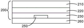
Fig. 1 is a schematic diagram of a barrier film construction.
Fig. 2 is a schematic illustration of an encapsulated organic device.
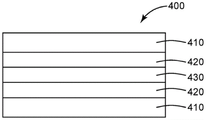
Fig. 3 is a schematic view of an ultra-barrier film coated with a clay-filled barrier adhesive.
Fig. 4 is a schematic diagram of a configuration for peeling off a test sample.
Fig. 5 is a schematic of a laminate construction for calcium testing.
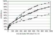
Fig. 6 is a graph of percent optical density loss versus time.
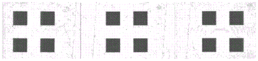
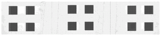
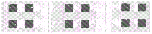
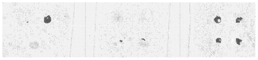
Fig. 7 presents photographs of calcium test specimens onto which food grade barrier film constructions were laminated.
FIG. 8 is a graph of percent optical density loss versus time.
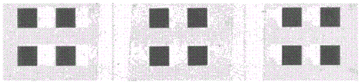
Fig. 9 presents photographs of calcium test specimens to which an ultra-barrier film construction was laminated.
Detailed Description
The barrier adhesive composition of the present invention comprises a resin system comprising a polyisobutylene resin. The polyisobutylene resin has a viscosity average molecular weight of about 100,000 to about 1,200,000g/mol, about 200,000 to about 1,100,000g/mol, or about 300,000 to about 900,000 g/mol.
In some embodiments, the resin system comprises a blend of a first polyisobutylene resin having a viscosity average molecular weight of about 300,000 to about 500,000g/mol, about 350,000 to about 450,000g/mol, or about 400,000g/mol, and (b) a second polyisobutylene resin having a molecular weight of about 700,000 to about 900,000g/mol, about 650,000g/mol to about 850,000g/mol, or about 800,000 g/mol.
In some embodiments, the resin system comprises about 65% to about 85% by weight of the polyisobutylene resin relative to the total weight of the resin system. In some embodiments, the resin system comprises about 15% to about 35%, about 20% to about 30%, or about 25% by weight of the first polyisobutylene resin relative to the total weight of the resin system. In some embodiments, the resin system comprises about 40% to about 60%, about 45% to about 55%, or about 50% by weight of the second polyisobutylene resin relative to the total weight of the resin system.
The polyisobutylene resin is generally a resin having a polyisobutylene resin skeleton in a main chain or a side chain. In some embodiments, the polyisobutylene resin is substantially a homopolymer of isobutylene, such as, for example, polyisobutylene resins available under the trade names OPPANOL (BASF AG) and GLISSO-PAL (BASF AG). Examples of suitable commercially available polyisobutylene resins include OPPANOL 30(Mv ═ 200,000), OPPANOL B50(Mv ═ 400,000), OPPANOL B80(Mv ═ 800,000), and OPPANOL B100(Mv ═ 1,110,000).
In some embodiments, the polyisobutylene resin comprises a copolymer of isobutylene, such as, for example, a synthetic rubber in which isobutylene is copolymerized with another monomer. Synthetic rubbers include BUTYL rubbers which are copolymers of mostly isobutylene with a small amount of isoprene, such as, for example, BUTYL rubbers available under the tradenames VISTANEX (Exxon chemical co.) and JSR BUTYL (Japan BUTYL polymer co., Ltd.)). Synthetic rubbers also include copolymers of mostly isobutylene with styrene, n-butene or butadiene. In some embodiments, a mixture of isobutylene homopolymer and butene rubber may be used. For example, the first polyisobutylene resin may comprise a homopolymer of isobutylene and the second polyisobutylene may comprise a butyl rubber, or the first polyisobutylene may comprise a butyl rubber and the second polyisobutylene may comprise a homopolymer of isobutylene. The first and second polyisobutylene resins may each comprise more than one resin.
The polyisobutylene resin generally has a solubility parameter (SP value, which is an index for characterizing the polarity of a compound) similar to that of the hydrogenated alicyclic hydrocarbon resin, and exhibits good compatibility (i.e., miscibility) with the hydrogenated alicyclic hydrocarbon resin, if used, so that a transparent film can be formed. In addition, the polyisobutylene resin has a low surface energy, and therefore can allow the adhesive to spread onto an adherend and minimize void generation at the interface. In addition, polyisobutylene resins have low glass transition temperatures and moisture permeability and are therefore suitable for use as matrix resins in adhesive encapsulating compositions.
The polyisobutylene resin may have desirable viscoelastic properties that are generally useful for imparting a desired degree of flow to the adhesive encapsulating composition. Strain rheometers can be used to determine the elastic (storage) modulus G' and the viscous (loss) modulus G "at various temperatures. The ratio tan (), G "/G ', can then be determined using G' and G". Generally, the higher the tan () value, the more viscous the material will resemble; the lower the tan () value, the more elastic the material resembles. In some embodiments, the polyisobutylene resin may be selected such that the adhesive encapsulating composition has a tan () value of at least about 0.5 at relatively low frequencies when the composition is at a temperature of about 70 ℃ to about 110 ℃. In this way, the composition is able to flow well over uneven surfaces and contains only a very small amount of internal bubbles or no internal bubbles at all.
The resin system of the present invention also comprises a tackifier. Generally, the tackifier may be any compound or mixture of compounds that enhances the tack of the adhesive encapsulating composition. It is desirable that the tackifier does not enhance moisture permeability. The tackifier may comprise a hydrogenated hydrocarbon resin, a partially hydrogenated hydrocarbon resin, a non-hydrogenated hydrocarbon resin, or a combination thereof. Preferably, the tackifier comprises a hydrogenated petroleum resin. In some embodiments, the resin system comprises from about 15% to about 35%, from about 20% to about 30%, or about 25% by weight tackifier, relative to the total weight of the resin system.
Examples of tackifiers include, but are not limited to, hydrogenated terpene-based resins (e.g., resins commercially available under the trade names CLEARON P, M, and K (Yasuhara Chemical)); hydrogenated resins or hydrogenated ESTER-based resins (for example, resins commercially available under the trade names FORAL AX (Hercules Inc.), FORAL 105(Hercules Inc.), PENCEL A (Arakawa Chemical Industries, Ltd.); ESTERGUM H (Takawa Chemical Industries, Ltd.) and SUPER ESTER A (Takawa Chemical Industries, Ltd.)); disproportionate resins or disproportionate ester-based resins (e.g., commercially available under the trade name PINECRYSTAL (seikagawa chemical industries, ltd.)); hydrogenated dicyclopentadienyl resin, which is a hydrogenated resin of a petroleum resin type C5, wherein the petroleum resin type C5 is obtained by copolymerizing C5 fractions (e.g., pentene, isoprene, piperine, and 1, 3-pentadiene) produced by thermal decomposition of naphtha (e.g., resins commercially available under the trade names ESCOREZ 5300 and 5400 series (Exxon Chemical Co.)), easotac H (Eastman Chemical Co.)))); partially hydrogenated aromatic modified dicyclopentadienyl resin (for example, a resin commercially available under the trade name ESCOREZ 5600 (exxonmobil chemical corporation)); a resin resulting from hydrogenation of a C9-type petroleum resin, wherein the C9-type petroleum resin is obtained by copolymerizing a C9 fraction resulting from thermal decomposition of naphtha, such as indene, vinyltoluene, and α -or β -methylstyrene (for example, a resin commercially available under the trade name ARCON P or ARCON M (seikagawa chemical industries, ltd.)); resins resulting from hydrogenation of the copolymerized petroleum resins of the above-mentioned C5 fraction and C9 fraction (for example, resins commercially available under the trade name IMARV (idemitsu petrochemical Co)).
Non-hydrogenated hydrocarbon resins include C5, C9, C5/C9 hydrocarbon resins, polyterpene resins, aromatic modified polyterpene resins or rosin derivatives. If a non-hydrogenated hydrocarbon resin is used, it is typically used in combination with another hydrogenated or partially hydrogenated tackifier.
In some embodiments, the tackifier comprises a hydrogenated hydrocarbon resin, particularly a hydrogenated cycloaliphatic hydrocarbon resin. Specific examples of hydrogenated alicyclic hydrocarbon resins include ESCOREZ5340 (exxonmobil chemical). In some embodiments, the hydrogenated cycloaliphatic hydrocarbon resin is a hydrogenated dicyclopentadiene-based resin because of the lower moisture permeability and transmittance of the resin. Hydrogenated cycloaliphatic hydrocarbon resins useful in the adhesive encapsulating composition typically have a weight average molecular weight of about 200 to 5,000 g/mol. In another embodiment, the hydrogenated cycloaliphatic hydrocarbon resin has a weight average molecular weight of from about 500 to 3,000 g/mol. If the weight average molecular weight exceeds 5,000g/mol, the thickening effect may be deteriorated or the compatibility with the polyisobutylene resin may be lowered.
The tackifier may have a softening temperature or softening point (ring and ball softening temperature) that may vary depending, at least in part, on the adhesion of the composition, the temperature of use, ease of production, and the like. The ring and ball softening temperature may typically be between about 50 ℃ and 200 ℃. In some embodiments, the ring and ball softening temperature is from about 80 ℃ to 150 ℃. If the ring and ball softening temperature is less than 80 deg.c, the tackifier may be separated and liquefied by heat generated when the electronic device emits light. When the organic electroluminescent device is directly encapsulated with the adhesive encapsulating composition, this may cause deterioration of organic layers (e.g., light emitting layer). On the other hand, if the ring and ball softening temperature exceeds 150 ℃, the amount of tackifier added is so low that satisfactory improvement of the relevant properties is not obtained.
In some embodiments, the tackifier comprises a hydrogenated hydrocarbon resin, particularly a hydrogenated cycloaliphatic hydrocarbon resin. Specific examples of hydrogenated alicyclic hydrocarbon resins include ESCOREZ5340 (exxonmobil chemical). In some embodiments, the hydrogenated cycloaliphatic hydrocarbon resin is a hydrogenated dicyclopentadiene-based resin because of the lower moisture permeability and transmittance of the resin. Hydrogenated cycloaliphatic hydrocarbon resins useful in the adhesive encapsulating composition typically have a weight average molecular weight of about 200 to 5,000 g/mol. In another embodiment, the hydrogenated cycloaliphatic hydrocarbon resin has a weight average molecular weight of from about 500 to 3,000 g/mol. If the weight average molecular weight exceeds 5,000g/mol, the thickening effect may be deteriorated or the compatibility with the polyisobutylene resin may be lowered.
The barrier adhesive composition of the present invention also comprises organically modified nanoclay. Nanoclays are typically cationically-substitutable minerals that have been treated with organic modifiers to be compatible with the resin system. In some embodiments, the longest dimension of the nanoclay is about 100 to about 1000 nm.
Suitable nanoclay materials include, for example, those in the geological categories of smectite (smectite), kaolin, illite, chlorite, serpentine, attapulgite, palygorskite, vermiculite, glauconite, sepiolite, and mixed layer clays. Smectites can include, for example, montmorillonite, bentonite, pyrophyllite, hectorite, saponite, sauconite, nontronite, saponite, beidellite, and volkonskoite. Kaolin can include, for example, kaolinite, dickite, nacrite, antigorite, anauxite, halloysite, indellite, and chrysotile. Illites include, for example, muscovite, paragonite, phlogopite, and biotite. The chlorite may include, for example, chlorite interlaminar vermiculite, phyllite, metagonite, syenite, phyllite, and clinochlorlite. Mixed layer clays may include, for example, kaolinite and vermiculite (vermiculitebiotite). These modifications and isomorphous substitutes for the layered clay minerals provide unique applications. Preferably, montmorillonite, bentonite or a combination thereof is used.
Suitable organic modifiers include, for example, organic modifiers having dimethylbenzyl hydrogenated tallow quaternary ammonium ion, bis (hydrogenated tallow) dimethyl quaternary ammonium ion, methyl tallow bis-2-hydroxyethyl quaternary ammonium ion, dimethyl hydrogenated tallow 2-ethylhexyl quaternary ammonium ion, or dimethyl dehydrogenated tallow quaternary ammonium ion.
In some embodiments, the barrier adhesive compositions of the present invention are solvent-based adhesives. Any useful solvent that dissolves the resin may be utilized. Examples of suitable solvents include heptane, toluene, xylene, benzene, ethylbenzene, and hexane (preferably heptane, toluene, or combinations thereof; more preferably heptane). In some embodiments, it may be preferred that the solvent have a boiling point of less than about 200 ℃.
In some embodiments, the solvent comprises from about 65% to about 95%, from about 70% to about 90%, from about 75% to about 85%, or about 80% by weight of the total barrier adhesive composition.
The barrier adhesive composition of the present invention can be prepared by various methods known to those skilled in the art. For example, the barrier adhesive composition may be prepared by thoroughly mixing the above components. For mixing the composition, any mixer may be used, such as a kneader or an extruder. In some embodiments, the composition may be prepared, for example, by: preparing a mixture of the resin system and a solvent, dispersing the organically modified nanoclay into the solvent, and then mixing the resin mixture with the nanoclay dispersion.
The barrier adhesive compositions of the present invention exhibit good visible light transmission and low haze. In some embodiments, the barrier adhesive composition has a visible light transmission of 90% or greater. In some embodiments, the barrier adhesive composition has a haze of about 3% or less, or about 2% or less.
The barrier adhesive compositions of the present invention are typically non-curable or non-reactive compositions. Non-curable compositions are advantageous because they do not require the use of migrating species such as initiators. They also eliminate the need for high temperature curing, which can damage the underlying devices. The composition may be, for example, a solvent-borne dry adhesive, a pressure sensitive adhesive, a contact adhesive, or a hot melt adhesive. Preferably, the composition is a solvent-based dry adhesive that hardens upon drying. As the solvent evaporates, the viscosity increases and the adhesive composition hardens.
The barrier adhesive composition of the present invention can be applied to a substrate, a device, or any device component by any useful coating process. Solvent-based dry adhesives are typically applied by brush, roller, bead or ribbon or spray. The barrier adhesive composition may be coated onto a suitable substrate to form a barrier adhesive article.
For example, the barrier adhesive composition may be coated onto a gas barrier film and allowed to dry to form an adhesive barrier film. The gas barrier film has low permeability to oxygen and can be used to help prevent items such as food, electronics, and pharmaceuticals from deteriorating by contact with oxygen. Typically, the food grade gas barrier film has less than about 1cm at 20 ℃ and 65% relative humidity3/m2Oxygen transmission rate per day. Preferably, the gas barrier film also has barrier properties against moisture.
Examples of the polymer gas barrier film include ethylene vinyl alcohol copolymer (EVOH) films such as polyethylene EVOH films and polypropylene EVOH films; polyamide films such as co-extruded polyamide/polyethylene films, co-extruded polypropylene/polyamide/polypropylene films; and polyethylene films such as low, medium or high density polyethylene films and coextruded polyethylene/ethylene vinyl acetate films. The polymeric gas barrier film may also be metallized, for example by coating the polymeric film with a thin layer of metal, such as aluminum.
Examples of the inorganic gas barrier film include films containing silicon oxide, silicon nitride, silicon oxynitride, aluminum oxide, diamond-like films, diamond-like glass, and foils such as aluminum foil.
Preferably, the gas barrier film is flexible. For some applications, it is also preferred that the gas barrier film is visible light transmissive. As used herein, the term "visible light transmissive" means having an average transmission of at least about 80%, preferably at least about 88% or 90%, in the visible portion of the spectrum (e.g., between 400nm and 700 nm).
For some applications, protection from moisture and oxygen is desirable. For particularly sensitive applications, an "ultra-barrier film" may be necessary. The ultra-barrier film typically has less than about 0.005cc/m at 23 ℃ and 90% RH2An oxygen transmission rate per day and a water vapor transmission rate of less than about 0.005g/m2 per day at 23 ℃ and 90% RH. Surprisingly, it has been found that the barrier properties of ultra-barrier films are substantially improved when these ultra-barrier films are coated with the barrier adhesive composition of the present invention.
Some superbarrier films are multilayer films that include an inorganic visible light transmissive layer disposed between polymer layers. One example of a suitable ultra-barrier film includes a visible light-transmissive inorganic barrier layer disposed between polymers having a glass transition temperature (Tg) that is greater than or equal to the glass transition temperature of thermally stable polyethylene terephthalate (HSPET).
A variety of polymers having a Tg greater than or equal to the Tg of HSPET may be employed. Particularly preferred are volatile monomers that form reasonably high Tg polymers. Preferably, the first polymer layer has a Tg greater than that of PMMA, more preferably a Tg of at least about 110 ℃, even more preferably at least about 150 ℃, and most preferably at least about 200 ℃. Particularly preferred monomers that may be used to form the first layer include urethane acrylates (e.g., CN-968, Tg ═ about 84 ℃ and CN-983, both commercially available from Sartomer Co.), isobornyl acrylate (e.g., SR-506, Tg ═ about 88 ℃), dipentaerythritol pentaacrylate (e.g., SR-399, Tg ═ about 90 ℃; commercially available from Sartomer), blends of epoxy acrylate and styrene (e.g., CN-120S80, Tg ═ about 95 ℃), ditrimethylolpropane tetraacrylate (e.g., SR-355, Tg ═ about 98 ℃; commercially available from Sartomer), diacrylate (e.g., SR-230, tg of about 100 ℃), 1, 3-butanediol diacrylate (e.g., SR-212 commercially available from sartomer, Tg of about 101 ℃), pentaacrylate (e.g., SR-9041 commercially available from sartomer, Tg of about 102 ℃), pentaerythritol tetraacrylate (e.g., SR-295 commercially available from sartomer, Tg of about 103 ℃), pentaerythritol triacrylate (e.g., R-444 commercially available from sartomer, Tg of about 103 ℃), ethoxylated (3) trimethylolpropane triacrylate (e.g., SR-454 commercially available from sartomer, Tg of about 103 ℃), ethoxylated (3) trimethylolpropane triacrylate (e.g., SR-HP commercially available from sartomer, Tg of about 454 ℃), ethoxylated (3) trimethylolpropane triacrylate (e.g., 454, Tg of about 103 ℃), alkoxylated trifunctional acrylate (e.g., SR-9008, Tg ═ about 103 ℃, commercially available from sartomer, dipropylene glycol diacrylate (e.g., SR-508, Tg ═ about 104 ℃, commercially available from sartomer), neopentyl glycol diacrylate (e.g., SR-247, Tg ═ about 107 ℃, commercially available from sartomer), ethoxylated (4) bisphenol a dimethacrylate (e.g., CD-450, Tg ═ about 108 ℃, commercially available from sartomer), cyclohexane dimethanol diacrylate (e.g., CD-406, Tg ℃., (e.g., SR-423, Tg ℃) commercially available from sartomer), isobornyl methacrylate (e.g., SR-833, Tg ═ about 110 ℃), cyclic diacrylate (e.g., SR-833, Tg ═ about 186 ℃, commercially available from sartomer, Tg ℃) and tris (2-hydroxyethyl) isocyanurate (e.g., isocyanurate, SR-368, Tg ═ about 272 c) commercially available from sartomer company, acrylates of the aforementioned methacrylates, and methacrylates of the aforementioned acrylates.
The first polymer layer may be formed by: the polymer is formed in situ by applying a layer of the monomer or oligomer to a substrate and crosslinking the layer, for example, by flash evaporation and vapor deposition of a radiation crosslinkable monomer, followed by crosslinking using, for example, an electron beam device, a UV light source, a discharge device, or other suitable means. The coating efficiency can be improved by cooling the carrier. The monomers or oligomers may also be applied to the substrate using conventional coating methods such as roll coating (e.g., gravure roll coating) or spray coating (e.g., electrostatic spray coating), and then crosslinked as described above. The first polymer layer may also be formed by applying a layer comprising an oligomer or polymer in a solvent and drying the thus applied layer to remove the solvent. Plasma polymerization may also be employed if a polymer layer is provided having a glassy state at high temperatures, with a glass transition temperature greater than or equal to that of HSPET. Most preferably, the first polymer layer is formed by flash evaporation and vapor deposition followed by in situ crosslinking, for example, as described in the following documents: U.S. Pat. Nos. 4,696,719(Bischoff), 4,722,515(Ham), 4,842,893(Yializis et al), 4,954,371(Yializis), 5,018,048(Shaw et al), 5,032,461(Shaw et al), 5,097,800(Shaw et al), 5,125,138(Shaw et al), 5,440,446(Shaw et al), 5,547,908(Furuzawa et al), 6,045,864(Lyons et al), 6,231,939(Shaw et al), and 6,214,422 (Yializis); published PCT patent application WO 00/26973(Delta V technologies, Inc.); shaw and m.g.langlois, "a New Vacuum processing for Coating Paper and Polymer Webs (a novel vapor deposition Process for Coating Paper and Polymer Webs)," 6th International Vacuum Coating Conference (6 th International Vacuum Coating Conference) (1992); shaw and M.G.Langlois, "A New High Speed Process for vapor Depositing Acrylate Thin Films: An Update," Society of Vacuum Coaters 36th annular technical conference Proceedings (Vacuum coating Association 36th Annual technical conference of technology) (1993); shaw and M.G.Langlois, "Use of vaporized acrylic Coatings to Improve the barrier properties of Metallized films," vacuum coating Association, 37 th annual technical conference (1994); d.g. shaw, m.roehrig, m.g. langlois and c.sheehan, "Use of Evaporated Acrylate Coatings to Smooth the surface of Polyester and Polypropylene Film Substrates" (using Evaporated Acrylate Coatings to Smooth the surface of Polyester and Polypropylene Film Substrates), RadTech (1996); J.Affinito, P.Martin, M.Gross, C.Coronado and E.Greenwell, "Vacuum deposited Polymer/Metal multilayer Films for optical applications Vacuum deposited Polymer/Metal Multi-layer Films" for optical applications, Thin Solid Films 270,43-48(1995), and J.D.Affinito, M.E.Gross, C.A.Coronado, G.L.Graff, E.N.Greenwell and P.M.Martin, "Polymer-Oxide Transmission barriers (Polymer-Oxide Transparent Barrier)", Vacuum coating Association 39 th annual technical conference (1996).
The smoothness and continuity of each polymer layer and its adhesion to the underlying layer are preferably enhanced by suitable pre-treatment. Preferred pretreatment protocols employ electrical discharge in the presence of a suitable reactive or non-reactive atmosphere (e.g., plasma, glow discharge, corona discharge, dielectric barrier discharge, or atmospheric pressure discharge); chemical pretreatment or flame pretreatment. These pretreatments help make the surface of the underlying layer more receptive to the formation of a subsequently applied polymer layer. Plasma pretreatment is particularly preferred. A separate adhesion promoting layer, which may have a different composition than the high Tg polymer layer, may also be used on top of the underlying layer to improve interlayer adhesion. The adhesion promoting layer can be, for example, a separate polymer layer or a metal-containing layer, such as a metal layer, a metal oxide layer, a metal nitride layer, or a metal oxynitride layer. The adhesion promoting layer may have a thickness of a few nanometers (e.g., 1nm or 2nm) to about 50nm, and may be thicker if desired.
The desired chemical composition and thickness of the first polymer layer depends in part on the nature and surface topography of the support. The thickness is preferably sufficient to provide a smooth, defect free surface to which the first inorganic barrier layer may subsequently be applied. For example, the first polymer layer may have a thickness of several nm (e.g., 2nm or 3nm) to about 5 μm, and may be thicker if desired.
One or more visible light-transmitting inorganic barrier layers separated by a polymer layer having a Tg greater than or equal to the Tg of HSPET are located atop the first polymer layer. These layers may be referred to as a "first inorganic barrier layer," a "second inorganic barrier layer," and a "second polymer layer," respectively. Additional inorganic barrier layers and polymeric layers may also be present, if desired, including polymeric layers that do not have a Tg greater than or equal to the Tg of the HSPET. However, each adjacent pair of inorganic barrier layers is preferably separated only by one or more polymer layers having a Tg greater than or equal to the Tg of the HSPET, and more preferably separated only by one or more polymer layers having a Tg greater than the Tg of the PMMA.
These inorganic barrier layers need not be identical. A variety of inorganic barrier materials may be employed. Preferred inorganic barrier materials include metal oxides, metal nitrides, metal carbides, metal oxynitrides, metal oxyborides, and combinations thereof, for example, silicon oxides such as silicon dioxide, aluminum oxides such as alumina, titanium oxides such as titanium dioxide, indium oxide, tin oxide, indium tin oxide ("ITO"), tantalum oxide, zirconium oxide, niobium oxide, boron carbide, tungsten carbide, silicon carbide, aluminum nitride, silicon nitride, boron nitride, aluminum oxynitride, silicon oxide, boron oxynitride, zirconium oxyboride, titanium oxyboride, and combinations thereof. Indium tin oxide, silicon oxide, aluminum oxide, and combinations thereof are particularly preferred inorganic barrier materials. ITO is an example of a particular class of ceramic materials that can become conductive if the relative proportions of the elemental constituents are properly selected. The inorganic barrier layer is preferably formed using techniques employed in the art of film metallization such as sputtering (e.g., cathode or planar magnetron sputtering), evaporation (e.g., resistive or e-beam evaporation), chemical vapor deposition, atomic layer deposition, electroplating, and the like. Most preferably, sputtering, e.g., reactive sputtering, is used to form the inorganic barrier layer. Enhanced barrier properties have been observed when the inorganic layer is formed by high energy deposition techniques such as sputtering compared to lower energy techniques such as conventional chemical vapor deposition processes. The smoothness and continuity of each inorganic barrier layer and its adhesion to the underlying layer may be improved by a pretreatment (e.g., plasma pretreatment) such as the methods described above with reference to the first polymer layer.
These inorganic barrier layers need not have the same thickness. The desired chemical composition and thickness of each inorganic barrier layer will depend in part on the nature and surface topography of the underlying layer and the desired optical characteristics of the barrier assembly. The inorganic barrier layer is preferably thick enough to be continuous and thin enough to ensure that the barrier component and the article containing the component have the desired degree of visible light transmission and flexibility. Each inorganic barrier layer preferably has a physical thickness (relative to the optical thickness) of from about 3nm to about 150nm, more preferably from about 4nm to about 75 nm.
The second polymer layers separating the first, second and any additional inorganic barrier layers need not be the same, nor need they have the same thickness. A variety of second polymer layer materials may be employed. Preferred second polymeric layer materials include those mentioned above with respect to the first polymeric layer. The preferred second polymer layer or layers are applied by flash evaporation and vapor deposition as described above with respect to the first polymer layer, followed by in situ crosslinking. A pretreatment such as that described above (e.g., a plasma pretreatment) is also preferably employed prior to formation of the second polymer layer. The desired chemical composition and thickness of the one or more second polymer layers depends in part on the nature and surface topography of the one or more underlying layers. The second polymer layer thickness is preferably sufficient to provide a smooth, defect-free surface to which the inorganic barrier layer can subsequently be applied. Typically, one or more of the second polymer layers may have a smaller thickness than the first polymer layer. For example, each second polymer layer may have a thickness of about 5nm to about 10 μm, and may be thicker if desired.
Flexible visible light-transmissive ultra-barrier films and methods of making the same are described, for example, in U.S. patent 7,940,004(Padiyath et al), which is incorporated herein by reference.
Commercially available ultra-barrier films include, for example, FTB3-50 and FTB 3-125, which are available from 3M company.
A gas barrier film coated with a layer of the adhesive barrier composition of the present invention may be disposed on a substrate. The substrate is preferably flexible and visible light transmissive. Suitable substrate materials include organic polymeric materials such as polyethylene terephthalate (PET), polyacrylates, polycarbonates, silicones, epoxies, silicone-functionalized epoxies, polyesters such as Mylar (e.i.du Pont de Nemours)&Co)), a polyimide such as Kapton H or Kapton E (manufactured by DuPont corporation), Apical AV (manufactured by Kanegafugi Chemical industry company), Uplix (manufactured by UBE industries, Inc.), polyethersulfone (PES manufactured by Sumitomo corporation), polyetherimide, polyethylene naphthalene (PEN), polymethylmethacrylate, styrene/acrylonitrile, styrene/maleic anhydride, polyoxymethylene, polyvinylnaphthalene, polyetheretherketone, polyaryletherketone, high Tg fluoropolymer (e.g., hexafluoropropylene, DYNEON of tetrafluoroethylene and ethylene)TMHTE terpolymers), poly-alpha-methylstyrene, polyarylates, polysulfones, polyphenylene ethers, polyamideimides, polyimides, polyphthalamides, polyethylenes, and polypropylenes. Colorless polyimides, cyclic olefin copolymers and cyclic olefin copolymers may also be utilized. Preferably, the substrate comprises PET.
Fig. 1 illustrates a cross-sectional structure of an exemplary barrier film construction 100, which includes a substrate 110, a gas barrier film 120 (preferably, an ultra-barrier film), and a barrier adhesive layer 130. In some embodiments, the barrier adhesive layer has a thickness of about 5 to about 50 μm. In some embodiments, the barrier film construction has a thickness of about 20 to about 250 μm.
In some embodiments, a device such as a release liner (140) may be used to protect the outer surface of the barrier adhesive layer. Any useful release liner may be used, such as, for example, a film or sheet treated with a release agent (e.g., a silicone resin). The end user may remove the release liner to attach the barrier construction to the device it will protect.
Alternatively, the end user may be provided with the barrier adhesive of the present invention disposed between two release liners.
The barrier film constructions of the present invention are useful for protecting OLED displays and solid state lighting, solar cells, electrophoretic and electrochromic displays, thin film batteries, quantum dot devices, sensors, and other organic electronic devices from oxygen and moisture. They are particularly suitable for applications requiring oxygen and moisture protection as well as flexibility and good optical transmission.
Figure 2 illustrates the barrier film construction of the present invention for encapsulating organic electronic devices such as, for example, OLEDs. The organic electronic device 250 is disposed on a device substrate 260. The organic electronic device 250 is encapsulated with a barrier film construction 200 comprising an ultra-barrier film 220 and a barrier adhesive layer 230, and a device substrate 260.
Examples:
Objects and advantages of this invention are further illustrated by the following examples, but the particular materials and amounts thereof recited in these examples, as well as other conditions and details, should not be construed to unduly limit this invention.
These examples are for illustrative purposes only and are not intended to limit the scope of the appended claims. All parts, percentages, ratios, and the like in the examples, as well as in the remainder of the specification, are by weight unless otherwise specified. Solvents and other reagents used were purchased from Sigma Aldrich Chemical Company of st louis, MO, st, unless otherwise specified.
Material
Escorez 5300 hydrogenated petroleum hydrocarbon resins were purchased from ExxonMobil, Houston, Kxas, ExxonMobil Chemical Company (Houston, TX)). Clearon P105 was obtained from Yasuhara Chemical (Fuchu-city, Japan)) in Japan. Polyisobutylene having the formula weight: (i)400,000g/mol (Oppanol B50 SF); (ii)800,000g/mol (Oppanol B80); (iii)1,110,000g/mol (OppanolB100) were all obtained from BASF (Florham Park, NJ) by Barsfu, Fremoledpak, N.J.. ExxonButyl 268 butyl rubber was obtained from Exxon Mobil, Houston, Kxas. Heptane and toluene were purchased from VWR International, inc (Radnor, PA), Radnor, PA. Xylene was obtained from EMD corporation (embd (Gibbstown, NJ)) in gibbs, NJ. SKC-12N and SKC-02N release liner webs were purchased from SKC Haas, Seoul, Korea. The M74F release liner web was obtained from the civic group of santoprene, gorgda, Italy (silicature, Godega di Sant' Urbano, Italy). Aldrich 682640 surface modified nanoclay was purchased from sigma Aldrich chemical of st louis, missouri. Claytone APA organophilic bentonite, Claytone AF organophilic bentonite, and Cloisite-20 micronized nanoclay were obtained from BYK (Wesel, Germany)) of Wezel, Germany.
Preparation of adhesive mixtures based on polyisobutene
The polyisobutylene and butyl rubber polymer resin were first cut into approximately 1 inch cubes. These resin cubes are then added to heptane or toluene together with a tackifier and the resulting formulation is mixed on a roller for 1-2 weeks. The polyisobutylene-based adhesive solution used in this work is described in table 1, and the "parts" listed in the "polymer resin" column of table 1 are parts by weight.
TABLE 1 polyisobutylene-based adhesive formulations。

Preparation of polyisobutene/clay mixtures
The smectite clay was dispersed in the organic solvent by adding the clay powder directly to heptane or toluene at the weight% solids specified in table 2. The clay was then mixed into the toluene or heptane solvent using the following method:
(i) t25 digital Ultra-Turrax high shear mixer (Wilmington, N.C.)Is/are as follows
 Works corporation (
 Works, inc., Wilmington, NC)) at a specified rotational speed for a specified time, or
(ii) Sonic Vibra Cell VCX750 ultrasonic instruments (sonic & Materials inc., Newtown, CT) are used at specified amplitudes for specified times.
TABLE 2 montmorillonite Clay Dispersion。


To prepare PE13-PE22, the smectite clay dispersions of table 2 were mixed with the polyisobutylene-based polymer solution of table 1 and mixed on a roller for 1 week. The resulting nanoclay-filled polyisobutylene-based adhesive formulations are summarized in table 3.
TABLE 3 nanoclay-filled polyisobutylene-based adhesive formulations for coating substrates。

Coating adhesive formulations onto film substrates
Three different film substrates were used: a porous polypropylene support membrane (F1); a 3M food grade oxide barrier film (F2); and 3M FTB3-50 (3M Company, Maplewood, MN) ultra-barrier film (F3). The properties of these film substrates are summarized in table 4.
TABLE 4 evaluation of film samples。
| Film identifier | Base film | Barrier layer | Film suppliers | Description of the film |
| F1 | Polypropylene | - | 3M | Polypropylene carrier film |
| F2 | PET | Sputtering oxides | 3M | 3M food grade barrier film |
| F3 | PET | Alternating polymer/inorganic layers | 3M | 3M FTB3-50 ultra-barrier film |
To prepare hand-spread samples, the adhesive mixture was coated onto SKC-12N release liner using a bench top notch bar coater. The coated sample was placed in an oven at 80 ℃ for 20 minutes to remove the solvent. The dry thickness of these samples was 25 μm. The M74F release liner was then laminated to the adhesive such that the adhesive was sandwiched between the two release liners. For CE2 and EX8, the adhesive was coated directly onto a 3M food grade barrier film (F2) and dried at 80 ℃ for 20 minutes. The M74F release liner was then laminated to the adhesive.
To prepare samples EX3 and EX9, the adhesive mixture was coated onto SKC-12N release liner using a Hirano experimental coater equipped with a notch bar. The adhesive was dried in an oven at 80 ℃ for 1 minute and in another oven at 130 ℃ for 1 minute. The dry thickness of these samples was 25 μm. The M74F release liner was then laminated to the adhesive such that the adhesive was sandwiched between the two release liners.
The adhesive was transferred from the release liner to a porous polypropylene film (F1) for bulk Water Vapor Transmission Rate (WVTR) testing, to a 3M food grade barrier film (F2) for calcium testing, and to a 3M ultra barrier film (F3) for peel testing, shear testing, and calcium testing. A schematic illustration of an adhesive coated barrier film construction is provided in fig. 3. A summary of all coated samples tested in this work is provided in table 5. The ratio in the column of "description information of adhesive" of table 5 is a weight ratio.
TABLE 5 evaluation of adhesive coated film samples。


Peel and shear test
Peel testing was performed according to ASTM D1876 using the T-peel test. The 25 μm adhesive was transferred from the release liner and laminated between two sheets of barrier film F3 such that the barrier coating on these barrier film sheets faced the adhesive as schematically shown in fig. 4. After transferring the adhesive to the barrier film, the standing time was 2 hours according to ASTM D1876. Samples 0.5 "wide were evaluated at room temperature. Peel tests were performed using an IMASS SP-2000 peel tester (IMASS, inc., accerd, MA) equipped with a SPA 2-02T-peel clamp. Three replicates of measurements were made and the average reported.
Shear testing was performed according to ASTM D3654/D3654M procedure A. The 25 μm adhesive was transferred to the barrier film with the barrier coating facing the adhesive. The adhesive backed barrier film was then adhered to a stainless steel plate. Shear adhesion performance was evaluated using the shear test bench of CREX Research Systems (Saint Paul, MN) of st Paul, minnesota at 23 ℃ and 50% RH. A 1kg weight was hung from each sample and the time taken for adhesive tack failure was recorded. Three replicates of measurements were made and the average reported.
Bulk WVTR testing
The moisture permeability of the adhesive formulation was tested using Mocon Permatran-W model 1/50G (Mocon, inc., Minneapolis, MN). These experiments were carried out at 40 ℃ and 100% RH using 50cm2The area of the sample is complete. The samples were prepared by transferring 25 μm thick patches of adhesive onto a porous polypropylene film (F1). The sample was then folded in half so that there was 50um of adhesive between the two porous polypropylene films. These samples were then placed into a Permatran instrument for testing.
Calcium test
The adhesive coated test substrates were first baked in a vacuum at 80 ℃ until the moisture was removed. A reflective calcium metal is thermally deposited on a designated area (e.g., a square array) of a glass substrate. An adhesive-backed film was disposed on the calcium-coated glass substrate, and this interlayer was laminated. A schematic of the laminate along with some approximate layer thicknesses is provided in fig. 5 (where 570 is a glass substrate and 580 is calcium). The adhesive was 25 μm thick in each example. The optical density at the initial time was measured using an optical densitometer. The samples were then kept in an ambient chamber at 60 ℃/90% relative humidity to accelerate aging. Optical density was measured twice daily over the first three days. The optical density was then measured once a day until the optical density became 50% of the initial density. The Water Vapor Transmission Rate (WVTR) is proportional to the time required for the optical density to reach 50% of its initial value. The barrier films used in the calcium test were either 3M FTB3-50 ultra barrier film (F3) or 3M food grade barrier film (F2).
Peel and shear data for filled and unfilled adhesive samples
The peel and shear data for clay-filled examples EX13-EX22 and unfilled adhesive control samples CE5-CE7 are provided in table 6. In table 6, the ratio in the column of "descriptive information of adhesive" is a weight ratio. Generally, the peel adhesion strength decreases when nanoclay is added to the adhesive, while the shear adhesion strength increases when clay filler is added. The adhesive properties of these samples are generally within an acceptable range for laminating the film to the substrate. The peel force of EX19 was not tested.
TABLE 6 evaluation of peel and shear test data for adhesive coated film samples。

Bulk WVTR data for filled and unfilled samples
The WVTR data for the two clay-filled adhesives and the two unfilled adhesive controls are provided in table 7. WVTR values were measured using a MOCON Permatran-W model 1/50G operating at 40 ℃ and 100% RH. The test sample comprised a 50 μm thick adhesive layer sandwiched between porous polypropylene films (F1). The addition of the nanoclay filler to the PIB adhesive CE1 did not result in a reduction in WVTR, and both EX24 and EX25 were characterized by higher WVTR values than CE 8.
TABLE 7 Water Vapor Transmission Rate (WVTR) through filled and unfilled adhesive samples。
| Examples | Adhesive agent | Description information of adhesive | WVTR(g/m2Sky) | |
| CE8 | CE1 | PIB | 4.073 | |
| | EX3 | 90/10 PIB/Clay | 4.452 | |
| EX25 | EX9 | 92/8 PIB/Clay | 6.158 | |
| CE9 | CE3 | Butyl rubber | 4.496 |
Calcium test Barrier Performance data for adhesive backed food grade Barrier films
Calcium test barrier performance data for adhesive backed food grade barrier film samples were prepared as described above and are summarized in table 8 and figures 6 and 7. Table 8 presents the time to 50% optical loss for the adhesive backed food grade barrier film samples CE10 and EX 26. Data were acquired using the calcium test in an environmental chamber at a temperature of 60 ℃ and a relative humidity of 90%. Figure 6 is a plot of percent optical density loss versus time for the samples described in table 8. The bold line with unfilled square marks is unfilled polyisobutylene adhesive (CE10) on a 3M food grade barrier film. The line with the star-shaped fill mark is a filled polyisobutylene adhesive (EX26) on a 3M food grade barrier film. The line with the solid filled square mark is the control PIB barrier adhesive on the 3M ultra-barrier film. Figure 7 presents photographs of calcium to which the food grade barrier film construction described in table 8 has been laminated. (a) One set of photographs in (a) was taken at time zero from a sample prepared using the unfilled polyisobutylene binder CE 10; (b) one set of photographs in (a) were taken at time zero from a sample prepared using nanoclay-filled polyisobutylene adhesive EX 26; (c) one set of photographs in (a) was taken at 9 hours from a sample prepared using the unfilled polyisobutylene binder CE 10; one set of photographs in (a) and (d) were taken at 9 hours from a sample prepared using the nanoclay-filled polyisobutylene adhesive EX 26.
Replacing the standard PIB adhesive with 10 wt% clay-filled adhesive did not improve the performance of the laminated food grade barrier film. The curves representing the percentage of optical density of the samples as a function of time in fig. 6 are nearly superimposed and the time to 50% optical loss measured for both samples is seven hours. In addition, the photographs of the calcium square arrays provided in fig. 7 are comparable. All these data indicate that the barrier properties of CE2 and EX8 are indistinguishable. According to JP2012193335 and US2014/0377554, this conclusion is surprising and these patents teach that adding a montmorillonite clay filler to a laminating adhesive will improve the performance of barrier film constructions having a wide range of barrier properties.
TABLE 8 time to 50% light loss for adhesive backed food grade barrier film samples CE10 and EX26。

Calcium test Barrier Performance data for adhesive backed ultraBarrier films
The calcium test barrier performance data for the adhesive backed ultrabarrier films are summarized in table 9 and fig. 6 and 7. All samples in table 9 contained a nanoclay-filled adhesive applied to a single layer ultra-barrier film as shown in fig. 5. Data were acquired using the calcium test in an environmental chamber at a temperature of 60 ℃ and a relative humidity of 90%. Figure 8 is a plot of percent optical density loss versus time for the samples described in table 9. The line with unfilled square marks is a polyisobutylene adhesive (EX27) with nanoclay dispersed on a 3M ultra-barrier film by high shear mixing. The line with the star-filled square markers was a polyisobutylene adhesive (EX28) with nanoclay dispersed on a 3M ultrabarrier film by sonication. The blue line with the solid filled square indicia is the control barrier adhesive (CE11 plus UV blocker) on the 3M ultra-barrier film. Fig. 9 presents a photograph of calcium to which an ultra-barrier film construction has been laminated. (a) One set of photographs in (a) was taken at time zero from a sample prepared using unfilled polyisobutylene adhesive CE11 plus a UV blocker; (b) the photograph in (a) was taken at time zero from a sample prepared using nanoclay-filled polyisobutylene adhesive EX 28; (c) the photographs in (a) were taken at 360 hours from samples prepared using unfilled polyisobutylene binder CE11 plus a UV blocker; (d) the photograph in (a) was taken at 360 hours from a sample prepared using nanoclay-filled polyisobutylene adhesive EX 28; (e) the photograph in (1) was taken at 959 hours from a sample prepared using unfilled polyisobutylene binder CE11 plus a UV blocker; the photographs in (a) and (f) were taken at 959 hours from a sample prepared using the nanoclay-filled polyisobutylene adhesive EX 28.
Unlike the WVTR measurement by the adhesive itself and the calcium test data for the food grade laminates, these samples show significant barrier property improvement when montmorillonite clay is added to the adhesive formulation. Each of the super-blocked samples with 25 μm thick clay-filled adhesive backing had a longer time to 50% optical loss compared to the comparable super-blocked samples laminated with 25 μm thick unfilled control adhesives (CE11 and CE 12). The time increase to 50% optical loss for the PIB sample ranged from 27% increase in EX30 with 2 wt% nanoclay filler to 183% increase in EX28 with 10 wt% nanoclay filler.
TABLE 9 Water vapor Transmission Performance data for adhesive backed ultrabarrier film samples。

Optical density data for control samples (identical to CE11 except that the adhesive contains some UV blocker), EX27, and EX28 are provided in fig. 8. Starting at about 150 hours, the curves for both EX27 and EX28 were significantly lower than the curve for the unfilled adhesive control sample. These lower curves indicate longer calcium lifetime and improved barrier performance. The clay in EX28 samples was dispersed using sonication, while the clay in EX27 was dispersed using a high shear mixer. The improved performance of EX28 compared to EX27 indicates that sonication is the preferred option for preparing clay-filled barrier adhesives.
Photographs of the calcium square array of unfilled control samples (CE11 plus UV blocker) and EX28 are provided in fig. 9. The calcium squares of the unfilled control almost completely disappeared after 959 hours of 60 ℃/90% RH ambient exposure as a result of water vapor permeating the barrier construction and reacting with calcium. In contrast, the calcium square of EX28 was mostly intact even after 959 hours of 60 ℃/90% RH ambient exposure. These images show the superior barrier properties of an ultra-barrier film laminated to a substrate with a clay-filled PIB adhesive compared to an ultra-barrier film laminated with a standard PIB adhesive. This property is not seen with the food grade oxide barrier film construction.
Various modifications and alterations to this invention will become apparent to those skilled in the art without departing from the scope and spirit of this invention. It should be understood that this invention is not intended to be unduly limited by the illustrative embodiments and examples set forth herein and that such examples and embodiments are presented by way of example only with the scope of the invention intended to be limited only by the claims set forth herein as follows.
Claims (18)
1. An encapsulated organic electronic device, comprising:
(a) a device substrate;
(b) an organic electronic device disposed on the device substrate;
(c) a barrier film construction disposed on at least a portion of the device substrate and the organic electronic device;
wherein the barrier film construction comprises (i) an ultra-barrier film having less than 0.005cc/m at 23 ℃ and 90% RH2Oxygen transmission rate per day and less than 0.005g/m at 23 ℃ and 90% RH2A water vapor transmission rate per day, and (ii) a barrier adhesive layer disposed on the ultra-barrier film, the adhesive layer comprising a barrier adhesive composition comprising a resin system and an organically modified nanoclay; wherein the resin system comprises a tackifier, a first polyisobutylene resin having a viscosity average molecular weight of 300,000 to 500,000g/mol, and a second polyisobutylene resin having a viscosity average molecular weight of 700,000 to 900,000 g/mol;
wherein the barrier adhesive layer and the device substrate encapsulate the organic electronic device.
2. The encapsulated organic electronic device of claim 1 wherein the first polyisobutylene resin has a viscosity average molecular weight of 350,000 to 450,000 g/mol.
3. The encapsulated organic electronic device of claim 1 or 2 wherein the second polyisobutylene resin has a viscosity average molecular weight of 650,000 to 850,000 g/mol.
4. The encapsulated organic electronic device of claim 1 wherein the resin system comprises 15 to 35 weight percent of the first polyisobutylene resin relative to the total weight of the resin system.
5. The encapsulated organic electronic device of claim 3 wherein the resin system comprises 40 to 60 weight percent of the second polyisobutylene resin relative to the total weight of the resin system.
6. The encapsulated organic electronic device of claim 1 wherein the resin system comprises 15 to 35 wt% of the tackifier, relative to the total weight of the resin system.
7. The encapsulated organic electronic device of claim 1 wherein the barrier adhesive composition comprises from 2 to 15 weight percent of the nanoclay relative to the total weight of the resin system and the nanoclay.
8. The encapsulated organic electronic device of claim 1 wherein the tackifier is a hydrogenated petroleum resin.
9. The encapsulated organic electronic device of claim 1 wherein the nanoclay is a bentonite clay or a montmorillonite nanoclay.
10. An encapsulated organic electronic device according to claim 1 wherein the nanoclay is modified with a quaternary ammonium ion.
11. An encapsulated organic electronic device according to claim 1 wherein the longest dimension of the nanoclay is 100nm to 1000 nm.
12. The encapsulated organic electronic device of claim 1 wherein the ultra-barrier film is a multilayer film comprising an inorganic visible light transmissive layer disposed between two polymer layers.
13. The encapsulated organic electronic device of claim 1 wherein the ultra-barrier film is a foil.
14. The encapsulated organic electronic device of claim 1 wherein the barrier film construction further comprises a substrate disposed on the ultra-barrier film opposite the barrier adhesive layer.
15. The encapsulated organic electronic device of claim 14 wherein the substrate comprises polyethylene terephthalate.
16. The encapsulated organic electronic device of claim 1 wherein the barrier film construction has a thickness of 20 to 250 μ ι η.
17. The encapsulated organic electronic device of claim 1 wherein the barrier adhesive layer has a thickness of 50 μ ι η or less.
18. The encapsulated organic electronic device of claim 1 wherein the organic electronic device is an organic light emitting diode.
Applications Claiming Priority (3)
| Application Number | Priority Date | Filing Date | Title |
|---|---|---|---|
| US201562206070P | 2015-08-17 | 2015-08-17 | |
| US62/206,070 | 2015-08-17 | ||
| PCT/US2016/046974 WO2017031031A1 (en) | 2015-08-17 | 2016-08-15 | Barrier film constructions |
Publications (2)
| Publication Number | Publication Date |
|---|---|
| CN107925010A CN107925010A (en) | 2018-04-17 |
| CN107925010B true CN107925010B (en) | 2020-11-06 |
Family
ID=58052255
Family Applications (1)
| Application Number | Title | Priority Date | Filing Date |
|---|---|---|---|
| CN201680048145.6A Active CN107925010B (en) | 2015-08-17 | 2016-08-15 | Barrier film construction |
Country Status (6)
| Country | Link |
|---|---|
| US (1) | US10581015B2 (en) |
| JP (2) | JP6956068B2 (en) |
| KR (1) | KR20180031793A (en) |
| CN (1) | CN107925010B (en) |
| TW (1) | TW201726851A (en) |
| WO (1) | WO2017031031A1 (en) |
Families Citing this family (8)
| Publication number | Priority date | Publication date | Assignee | Title |
|---|---|---|---|---|
| JP2018529803A (en) | 2015-08-17 | 2018-10-11 | スリーエム イノベイティブ プロパティズ カンパニー | Nano clay filled barrier adhesive composition |
| CN109415607B (en) * | 2016-06-16 | 2022-08-09 | 3M创新有限公司 | Nanoparticle filled barrier adhesive compositions |
| JP6903992B2 (en) * | 2017-03-27 | 2021-07-14 | 味の素株式会社 | Encapsulating resin composition and encapsulating sheet |
| US20180309089A1 (en) | 2017-04-21 | 2018-10-25 | Kateeva, Inc. | Compositions and Techniques for Forming Organic Thin Films |
| US20200123419A1 (en) | 2017-04-21 | 2020-04-23 | 3M Innovative Properties Company | Barrier adhesive compositions and articles |
| WO2019111182A1 (en) | 2017-12-06 | 2019-06-13 | 3M Innovative Properties Company | Barrier adhesive compositions and articles |
| US11784282B2 (en) | 2018-10-26 | 2023-10-10 | Samsung Electronics Co., Ltd. | Quantum dot display device |
| KR102496596B1 (en) * | 2020-11-25 | 2023-02-06 | 엘지디스플레이 주식회사 | Aluminized sealing adhesive film with excellent barrier properties and organic light emitting diode including thereof |
Family Cites Families (34)
| Publication number | Priority date | Publication date | Assignee | Title |
|---|---|---|---|---|
| US5018048A (en) | 1983-12-19 | 1991-05-21 | Spectrum Control, Inc. | Miniaturized monolithic multi-layer capacitor and apparatus and method for making |
| US5032461A (en) | 1983-12-19 | 1991-07-16 | Spectrum Control, Inc. | Method of making a multi-layered article |
| US4842893A (en) | 1983-12-19 | 1989-06-27 | Spectrum Control, Inc. | High speed process for coating substrates |
| US5097800A (en) | 1983-12-19 | 1992-03-24 | Spectrum Control, Inc. | High speed apparatus for forming capacitors |
| US5125138A (en) | 1983-12-19 | 1992-06-30 | Spectrum Control, Inc. | Miniaturized monolithic multi-layer capacitor and apparatus and method for making same |
| US4722515A (en) | 1984-11-06 | 1988-02-02 | Spectrum Control, Inc. | Atomizing device for vaporization |
| EP0242460A1 (en) | 1985-01-18 | 1987-10-28 | SPECTRUM CONTROL, INC. (a Pennsylvania corporation) | Monomer atomizer for vaporization |
| US4954371A (en) | 1986-06-23 | 1990-09-04 | Spectrum Control, Inc. | Flash evaporation of monomer fluids |
| JP2825736B2 (en) | 1993-07-30 | 1998-11-18 | 京セラ株式会社 | Dielectric ceramic composition and package for housing semiconductor element |
| US5440446A (en) | 1993-10-04 | 1995-08-08 | Catalina Coatings, Inc. | Acrylate coating material |
| JP3101682B2 (en) | 1993-10-04 | 2000-10-23 | プレステック,インコーポレイティド | Crosslinked acrylate coating materials useful for forming dielectric and oxygen barriers in capacitors |
| US6083628A (en) | 1994-11-04 | 2000-07-04 | Sigma Laboratories Of Arizona, Inc. | Hybrid polymer film |
| US5916685A (en) | 1996-07-09 | 1999-06-29 | Tetra Laval Holdings & Finance, Sa | Transparent high barrier multilayer structure |
| US6045864A (en) | 1997-12-01 | 2000-04-04 | 3M Innovative Properties Company | Vapor coating method |
| AU1339700A (en) | 1998-11-02 | 2000-05-22 | Presstek, Inc. | Transparent conductive oxides for plastic flat panel displays |
| CN1714460A (en) * | 2000-11-02 | 2005-12-28 | 3M创新有限公司 | Brightness enhancement of emissive displays |
| JP2002260847A (en) * | 2001-02-27 | 2002-09-13 | Bando Chem Ind Ltd | Electroluminescence element sealing film and sealed organic electroluminescence element |
| US7018713B2 (en) | 2003-04-02 | 2006-03-28 | 3M Innovative Properties Company | Flexible high-temperature ultrabarrier |
| US9493348B2 (en) | 2006-11-06 | 2016-11-15 | Agency For Science, Technology And Research | Nanoparticulate encapsulation barrier stack |
| US8241713B2 (en) * | 2007-02-21 | 2012-08-14 | 3M Innovative Properties Company | Moisture barrier coatings for organic light emitting diode devices |
| KR101563025B1 (en) * | 2007-12-28 | 2015-10-23 | 쓰리엠 이노베이티브 프로퍼티즈 컴파니 | Flexible encapsulating films and a method of making the same |
| JP5890177B2 (en) * | 2008-06-02 | 2016-03-22 | スリーエム イノベイティブ プロパティズ カンパニー | Adhesive encapsulating composition and electronic device produced using the same |
| EP2502962B1 (en) * | 2009-11-18 | 2015-03-04 | Ajinomoto Co., Inc. | Resin composition |
| KR101213499B1 (en) | 2009-12-31 | 2012-12-20 | 삼성디스플레이 주식회사 | Barrier film composites, display apparatus comprising the same |
| JP2012193335A (en) | 2010-09-27 | 2012-10-11 | Dainippon Printing Co Ltd | Tacky composition, laminate and image display device |
| US8663407B2 (en) * | 2010-11-17 | 2014-03-04 | 3M Innovative Properties Company | Isobutylene (Co)polymeric adhesive composition |
| KR101308480B1 (en) * | 2011-06-14 | 2013-09-16 | 엘지디스플레이 주식회사 | Plastic organic light emitting display panel and method of fabricating the same |
| KR20140060265A (en) * | 2011-06-28 | 2014-05-19 | 린텍 가부시키가이샤 | Adhesive composition and adhesive sheet |
| TWI488930B (en) * | 2012-03-12 | 2015-06-21 | Lg Chemical Ltd | Pressure- sensitive adhesive composition |
| US8796376B2 (en) * | 2012-03-26 | 2014-08-05 | Exxonmobil Chemical Patents Inc. | Functionalized polymers and oligomers |
| JP6534932B2 (en) * | 2012-10-18 | 2019-06-26 | テラ‐バリア フィルムズ プライベート リミテッド | Encapsulated barrier stack |
| KR101426741B1 (en) | 2013-01-08 | 2014-08-05 | 김한기 | Electronic inhaler with battery in a single body |
| JP2014231586A (en) * | 2013-05-30 | 2014-12-11 | 大日本印刷株式会社 | Adhesive composition and adhesive sheet using the same |
| JP2018529803A (en) | 2015-08-17 | 2018-10-11 | スリーエム イノベイティブ プロパティズ カンパニー | Nano clay filled barrier adhesive composition |
-
2016
- 2016-08-15 US US15/752,859 patent/US10581015B2/en active Active
- 2016-08-15 CN CN201680048145.6A patent/CN107925010B/en active Active
- 2016-08-15 WO PCT/US2016/046974 patent/WO2017031031A1/en active Application Filing
- 2016-08-15 JP JP2018508199A patent/JP6956068B2/en active Active
- 2016-08-15 KR KR1020187007184A patent/KR20180031793A/en not_active Application Discontinuation
- 2016-08-16 TW TW105126163A patent/TW201726851A/en unknown
-
2021
- 2021-07-29 JP JP2021123808A patent/JP7186267B2/en active Active
Also Published As
| Publication number | Publication date |
|---|---|
| US10581015B2 (en) | 2020-03-03 |
| KR20180031793A (en) | 2018-03-28 |
| US20180248149A1 (en) | 2018-08-30 |
| JP2021176709A (en) | 2021-11-11 |
| TW201726851A (en) | 2017-08-01 |
| JP7186267B2 (en) | 2022-12-08 |
| WO2017031031A1 (en) | 2017-02-23 |
| JP6956068B2 (en) | 2021-10-27 |
| CN107925010A (en) | 2018-04-17 |
| JP2018529550A (en) | 2018-10-11 |
Similar Documents
| Publication | Publication Date | Title |
|---|---|---|
| CN107925010B (en) | Barrier film construction | |
| CN107922805B (en) | Nanoclay-filled barrier adhesive composition | |
| CN109415607B (en) | Nanoparticle filled barrier adhesive compositions | |
| US10894903B2 (en) | Nanoparticle filled barrier adhesive compositions | |
| US8460969B2 (en) | Method for encapsulating an electronic arrangement | |
| WO2015068805A1 (en) | Sealing resin composition | |
| CN110536945B (en) | Barrier adhesive compositions and articles | |
| US11591501B2 (en) | Barrier adhesive compositions and articles | |
| TW202204159A (en) | Sealing sheet and polymer composition layer to provide a sealing sheet in which pre-drying of the polymer composition layer can be omitted and of which a moisture content is sufficiently reduced |
Legal Events
| Date | Code | Title | Description |
|---|---|---|---|
| PB01 | Publication | ||
| PB01 | Publication | ||
| SE01 | Entry into force of request for substantive examination | ||
| SE01 | Entry into force of request for substantive examination | ||
| GR01 | Patent grant | ||
| GR01 | Patent grant |