CN107889466B - Lighting system and method for improving alertness of a person - Google Patents
Lighting system and method for improving alertness of a person Download PDFInfo
- Publication number
- CN107889466B CN107889466B CN201680020900.XA CN201680020900A CN107889466B CN 107889466 B CN107889466 B CN 107889466B CN 201680020900 A CN201680020900 A CN 201680020900A CN 107889466 B CN107889466 B CN 107889466B
- Authority
- CN
- China
- Prior art keywords
- light
- controller
- environment
- lighting system
- pulse
- Prior art date
- Legal status (The legal status is an assumption and is not a legal conclusion. Google has not performed a legal analysis and makes no representation as to the accuracy of the status listed.)
- Active
Links
- 230000036626 alertness Effects 0.000 title claims abstract description 44
- 238000000034 method Methods 0.000 title claims description 11
- 238000005286 illumination Methods 0.000 claims abstract description 16
- 230000002045 lasting effect Effects 0.000 claims abstract description 6
- 230000000694 effects Effects 0.000 claims description 25
- 230000004044 response Effects 0.000 claims description 10
- 230000008859 change Effects 0.000 claims description 5
- 238000004590 computer program Methods 0.000 claims description 4
- 230000000007 visual effect Effects 0.000 claims description 4
- 238000012545 processing Methods 0.000 claims description 3
- 230000003247 decreasing effect Effects 0.000 claims 2
- 230000009286 beneficial effect Effects 0.000 description 6
- 206010041349 Somnolence Diseases 0.000 description 5
- 230000001960 triggered effect Effects 0.000 description 5
- 238000004891 communication Methods 0.000 description 4
- 239000011521 glass Substances 0.000 description 3
- 238000000227 grinding Methods 0.000 description 3
- YJPIGAIKUZMOQA-UHFFFAOYSA-N Melatonin Natural products COC1=CC=C2N(C(C)=O)C=C(CCN)C2=C1 YJPIGAIKUZMOQA-UHFFFAOYSA-N 0.000 description 2
- 206010048232 Yawning Diseases 0.000 description 2
- 230000004913 activation Effects 0.000 description 2
- 230000003190 augmentative effect Effects 0.000 description 2
- 210000004556 brain Anatomy 0.000 description 2
- 238000001514 detection method Methods 0.000 description 2
- 238000005265 energy consumption Methods 0.000 description 2
- 230000010354 integration Effects 0.000 description 2
- 230000001795 light effect Effects 0.000 description 2
- DRLFMBDRBRZALE-UHFFFAOYSA-N melatonin Chemical compound COC1=CC=C2NC=C(CCNC(C)=O)C2=C1 DRLFMBDRBRZALE-UHFFFAOYSA-N 0.000 description 2
- 229960003987 melatonin Drugs 0.000 description 2
- OYPRJOBELJOOCE-UHFFFAOYSA-N Calcium Chemical compound [Ca] OYPRJOBELJOOCE-UHFFFAOYSA-N 0.000 description 1
- 241001124569 Lycaenidae Species 0.000 description 1
- 241001282135 Poromitra oscitans Species 0.000 description 1
- 229930003316 Vitamin D Natural products 0.000 description 1
- QYSXJUFSXHHAJI-XFEUOLMDSA-N Vitamin D3 Natural products C1(/[C@@H]2CC[C@@H]([C@]2(CCC1)C)[C@H](C)CCCC(C)C)=C/C=C1\C[C@@H](O)CCC1=C QYSXJUFSXHHAJI-XFEUOLMDSA-N 0.000 description 1
- 238000013459 approach Methods 0.000 description 1
- 230000005540 biological transmission Effects 0.000 description 1
- 230000036760 body temperature Effects 0.000 description 1
- 229910052791 calcium Inorganic materials 0.000 description 1
- 239000011575 calcium Substances 0.000 description 1
- 230000002060 circadian Effects 0.000 description 1
- 230000027288 circadian rhythm Effects 0.000 description 1
- 230000002301 combined effect Effects 0.000 description 1
- 230000001010 compromised effect Effects 0.000 description 1
- 238000010586 diagram Methods 0.000 description 1
- 230000007613 environmental effect Effects 0.000 description 1
- 230000004424 eye movement Effects 0.000 description 1
- 230000001815 facial effect Effects 0.000 description 1
- 238000001914 filtration Methods 0.000 description 1
- 238000003306 harvesting Methods 0.000 description 1
- 238000009776 industrial production Methods 0.000 description 1
- 238000002955 isolation Methods 0.000 description 1
- 230000033001 locomotion Effects 0.000 description 1
- 238000004519 manufacturing process Methods 0.000 description 1
- 230000003340 mental effect Effects 0.000 description 1
- 239000000203 mixture Substances 0.000 description 1
- 238000012986 modification Methods 0.000 description 1
- 230000004048 modification Effects 0.000 description 1
- 230000003287 optical effect Effects 0.000 description 1
- 230000002093 peripheral effect Effects 0.000 description 1
- 230000035790 physiological processes and functions Effects 0.000 description 1
- 230000010287 polarization Effects 0.000 description 1
- ZRHANBBTXQZFSP-UHFFFAOYSA-M potassium;4-amino-3,5,6-trichloropyridine-2-carboxylate Chemical compound [K+].NC1=C(Cl)C(Cl)=NC(C([O-])=O)=C1Cl ZRHANBBTXQZFSP-UHFFFAOYSA-M 0.000 description 1
- 230000001681 protective effect Effects 0.000 description 1
- 230000035484 reaction time Effects 0.000 description 1
- 230000002040 relaxant effect Effects 0.000 description 1
- 230000029058 respiratory gaseous exchange Effects 0.000 description 1
- 230000003595 spectral effect Effects 0.000 description 1
- 238000001356 surgical procedure Methods 0.000 description 1
- 230000001360 synchronised effect Effects 0.000 description 1
- 230000007704 transition Effects 0.000 description 1
- 235000019166 vitamin D Nutrition 0.000 description 1
- 239000011710 vitamin D Substances 0.000 description 1
- 150000003710 vitamin D derivatives Chemical class 0.000 description 1
- 229940046008 vitamin d Drugs 0.000 description 1
Images
Classifications
-
- A—HUMAN NECESSITIES
- A61—MEDICAL OR VETERINARY SCIENCE; HYGIENE
- A61M—DEVICES FOR INTRODUCING MEDIA INTO, OR ONTO, THE BODY; DEVICES FOR TRANSDUCING BODY MEDIA OR FOR TAKING MEDIA FROM THE BODY; DEVICES FOR PRODUCING OR ENDING SLEEP OR STUPOR
- A61M21/00—Other devices or methods to cause a change in the state of consciousness; Devices for producing or ending sleep by mechanical, optical, or acoustical means, e.g. for hypnosis
-
- A—HUMAN NECESSITIES
- A61—MEDICAL OR VETERINARY SCIENCE; HYGIENE
- A61B—DIAGNOSIS; SURGERY; IDENTIFICATION
- A61B5/00—Measuring for diagnostic purposes; Identification of persons
- A61B5/16—Devices for psychotechnics; Testing reaction times ; Devices for evaluating the psychological state
- A61B5/18—Devices for psychotechnics; Testing reaction times ; Devices for evaluating the psychological state for vehicle drivers or machine operators
-
- A—HUMAN NECESSITIES
- A61—MEDICAL OR VETERINARY SCIENCE; HYGIENE
- A61N—ELECTROTHERAPY; MAGNETOTHERAPY; RADIATION THERAPY; ULTRASOUND THERAPY
- A61N5/00—Radiation therapy
- A61N5/06—Radiation therapy using light
- A61N5/0613—Apparatus adapted for a specific treatment
- A61N5/0618—Psychological treatment
-
- B60K35/28—
-
- B—PERFORMING OPERATIONS; TRANSPORTING
- B60—VEHICLES IN GENERAL
- B60Q—ARRANGEMENT OF SIGNALLING OR LIGHTING DEVICES, THE MOUNTING OR SUPPORTING THEREOF OR CIRCUITS THEREFOR, FOR VEHICLES IN GENERAL
- B60Q3/00—Arrangement of lighting devices for vehicle interiors; Lighting devices specially adapted for vehicle interiors
- B60Q3/10—Arrangement of lighting devices for vehicle interiors; Lighting devices specially adapted for vehicle interiors for dashboards
- B60Q3/16—Circuits; Control arrangements
- B60Q3/18—Circuits; Control arrangements for varying the light intensity
-
- B—PERFORMING OPERATIONS; TRANSPORTING
- B60—VEHICLES IN GENERAL
- B60Q—ARRANGEMENT OF SIGNALLING OR LIGHTING DEVICES, THE MOUNTING OR SUPPORTING THEREOF OR CIRCUITS THEREFOR, FOR VEHICLES IN GENERAL
- B60Q3/00—Arrangement of lighting devices for vehicle interiors; Lighting devices specially adapted for vehicle interiors
- B60Q3/80—Circuits; Control arrangements
-
- B—PERFORMING OPERATIONS; TRANSPORTING
- B60—VEHICLES IN GENERAL
- B60Q—ARRANGEMENT OF SIGNALLING OR LIGHTING DEVICES, THE MOUNTING OR SUPPORTING THEREOF OR CIRCUITS THEREFOR, FOR VEHICLES IN GENERAL
- B60Q9/00—Arrangement or adaptation of signal devices not provided for in one of main groups B60Q1/00 - B60Q7/00, e.g. haptic signalling
-
- H—ELECTRICITY
- H05—ELECTRIC TECHNIQUES NOT OTHERWISE PROVIDED FOR
- H05B—ELECTRIC HEATING; ELECTRIC LIGHT SOURCES NOT OTHERWISE PROVIDED FOR; CIRCUIT ARRANGEMENTS FOR ELECTRIC LIGHT SOURCES, IN GENERAL
- H05B45/00—Circuit arrangements for operating light-emitting diodes [LED]
- H05B45/10—Controlling the intensity of the light
-
- H—ELECTRICITY
- H05—ELECTRIC TECHNIQUES NOT OTHERWISE PROVIDED FOR
- H05B—ELECTRIC HEATING; ELECTRIC LIGHT SOURCES NOT OTHERWISE PROVIDED FOR; CIRCUIT ARRANGEMENTS FOR ELECTRIC LIGHT SOURCES, IN GENERAL
- H05B45/00—Circuit arrangements for operating light-emitting diodes [LED]
- H05B45/20—Controlling the colour of the light
-
- H—ELECTRICITY
- H05—ELECTRIC TECHNIQUES NOT OTHERWISE PROVIDED FOR
- H05B—ELECTRIC HEATING; ELECTRIC LIGHT SOURCES NOT OTHERWISE PROVIDED FOR; CIRCUIT ARRANGEMENTS FOR ELECTRIC LIGHT SOURCES, IN GENERAL
- H05B47/00—Circuit arrangements for operating light sources in general, i.e. where the type of light source is not relevant
- H05B47/10—Controlling the light source
- H05B47/105—Controlling the light source in response to determined parameters
- H05B47/115—Controlling the light source in response to determined parameters by determining the presence or movement of objects or living beings
- H05B47/125—Controlling the light source in response to determined parameters by determining the presence or movement of objects or living beings by using cameras
-
- H—ELECTRICITY
- H05—ELECTRIC TECHNIQUES NOT OTHERWISE PROVIDED FOR
- H05B—ELECTRIC HEATING; ELECTRIC LIGHT SOURCES NOT OTHERWISE PROVIDED FOR; CIRCUIT ARRANGEMENTS FOR ELECTRIC LIGHT SOURCES, IN GENERAL
- H05B47/00—Circuit arrangements for operating light sources in general, i.e. where the type of light source is not relevant
- H05B47/10—Controlling the light source
- H05B47/16—Controlling the light source by timing means
-
- A—HUMAN NECESSITIES
- A61—MEDICAL OR VETERINARY SCIENCE; HYGIENE
- A61M—DEVICES FOR INTRODUCING MEDIA INTO, OR ONTO, THE BODY; DEVICES FOR TRANSDUCING BODY MEDIA OR FOR TAKING MEDIA FROM THE BODY; DEVICES FOR PRODUCING OR ENDING SLEEP OR STUPOR
- A61M21/00—Other devices or methods to cause a change in the state of consciousness; Devices for producing or ending sleep by mechanical, optical, or acoustical means, e.g. for hypnosis
- A61M2021/0005—Other devices or methods to cause a change in the state of consciousness; Devices for producing or ending sleep by mechanical, optical, or acoustical means, e.g. for hypnosis by the use of a particular sense, or stimulus
- A61M2021/0044—Other devices or methods to cause a change in the state of consciousness; Devices for producing or ending sleep by mechanical, optical, or acoustical means, e.g. for hypnosis by the use of a particular sense, or stimulus by the sight sense
-
- A—HUMAN NECESSITIES
- A61—MEDICAL OR VETERINARY SCIENCE; HYGIENE
- A61M—DEVICES FOR INTRODUCING MEDIA INTO, OR ONTO, THE BODY; DEVICES FOR TRANSDUCING BODY MEDIA OR FOR TAKING MEDIA FROM THE BODY; DEVICES FOR PRODUCING OR ENDING SLEEP OR STUPOR
- A61M21/00—Other devices or methods to cause a change in the state of consciousness; Devices for producing or ending sleep by mechanical, optical, or acoustical means, e.g. for hypnosis
- A61M2021/0005—Other devices or methods to cause a change in the state of consciousness; Devices for producing or ending sleep by mechanical, optical, or acoustical means, e.g. for hypnosis by the use of a particular sense, or stimulus
- A61M2021/0083—Other devices or methods to cause a change in the state of consciousness; Devices for producing or ending sleep by mechanical, optical, or acoustical means, e.g. for hypnosis by the use of a particular sense, or stimulus especially for waking up
-
- A—HUMAN NECESSITIES
- A61—MEDICAL OR VETERINARY SCIENCE; HYGIENE
- A61M—DEVICES FOR INTRODUCING MEDIA INTO, OR ONTO, THE BODY; DEVICES FOR TRANSDUCING BODY MEDIA OR FOR TAKING MEDIA FROM THE BODY; DEVICES FOR PRODUCING OR ENDING SLEEP OR STUPOR
- A61M2205/00—General characteristics of the apparatus
- A61M2205/33—Controlling, regulating or measuring
- A61M2205/3368—Temperature
-
- A—HUMAN NECESSITIES
- A61—MEDICAL OR VETERINARY SCIENCE; HYGIENE
- A61M—DEVICES FOR INTRODUCING MEDIA INTO, OR ONTO, THE BODY; DEVICES FOR TRANSDUCING BODY MEDIA OR FOR TAKING MEDIA FROM THE BODY; DEVICES FOR PRODUCING OR ENDING SLEEP OR STUPOR
- A61M2205/00—General characteristics of the apparatus
- A61M2205/33—Controlling, regulating or measuring
- A61M2205/3375—Acoustical, e.g. ultrasonic, measuring means
-
- A—HUMAN NECESSITIES
- A61—MEDICAL OR VETERINARY SCIENCE; HYGIENE
- A61M—DEVICES FOR INTRODUCING MEDIA INTO, OR ONTO, THE BODY; DEVICES FOR TRANSDUCING BODY MEDIA OR FOR TAKING MEDIA FROM THE BODY; DEVICES FOR PRODUCING OR ENDING SLEEP OR STUPOR
- A61M2230/00—Measuring parameters of the user
- A61M2230/005—Parameter used as control input for the apparatus
-
- A—HUMAN NECESSITIES
- A61—MEDICAL OR VETERINARY SCIENCE; HYGIENE
- A61M—DEVICES FOR INTRODUCING MEDIA INTO, OR ONTO, THE BODY; DEVICES FOR TRANSDUCING BODY MEDIA OR FOR TAKING MEDIA FROM THE BODY; DEVICES FOR PRODUCING OR ENDING SLEEP OR STUPOR
- A61M2230/00—Measuring parameters of the user
- A61M2230/63—Motion, e.g. physical activity
-
- B—PERFORMING OPERATIONS; TRANSPORTING
- B60—VEHICLES IN GENERAL
- B60Q—ARRANGEMENT OF SIGNALLING OR LIGHTING DEVICES, THE MOUNTING OR SUPPORTING THEREOF OR CIRCUITS THEREFOR, FOR VEHICLES IN GENERAL
- B60Q3/00—Arrangement of lighting devices for vehicle interiors; Lighting devices specially adapted for vehicle interiors
- B60Q3/70—Arrangement of lighting devices for vehicle interiors; Lighting devices specially adapted for vehicle interiors characterised by the purpose
- B60Q3/72—Arrangement of lighting devices for vehicle interiors; Lighting devices specially adapted for vehicle interiors characterised by the purpose for preventing the driver from being dazzled
-
- B—PERFORMING OPERATIONS; TRANSPORTING
- B60—VEHICLES IN GENERAL
- B60W—CONJOINT CONTROL OF VEHICLE SUB-UNITS OF DIFFERENT TYPE OR DIFFERENT FUNCTION; CONTROL SYSTEMS SPECIALLY ADAPTED FOR HYBRID VEHICLES; ROAD VEHICLE DRIVE CONTROL SYSTEMS FOR PURPOSES NOT RELATED TO THE CONTROL OF A PARTICULAR SUB-UNIT
- B60W2540/00—Input parameters relating to occupants
- B60W2540/22—Psychological state; Stress level or workload
-
- G—PHYSICS
- G08—SIGNALLING
- G08B—SIGNALLING OR CALLING SYSTEMS; ORDER TELEGRAPHS; ALARM SYSTEMS
- G08B21/00—Alarms responsive to a single specified undesired or abnormal condition and not otherwise provided for
- G08B21/02—Alarms for ensuring the safety of persons
- G08B21/06—Alarms for ensuring the safety of persons indicating a condition of sleep, e.g. anti-dozing alarms
-
- G—PHYSICS
- G09—EDUCATION; CRYPTOGRAPHY; DISPLAY; ADVERTISING; SEALS
- G09G—ARRANGEMENTS OR CIRCUITS FOR CONTROL OF INDICATING DEVICES USING STATIC MEANS TO PRESENT VARIABLE INFORMATION
- G09G3/00—Control arrangements or circuits, of interest only in connection with visual indicators other than cathode-ray tubes
- G09G3/20—Control arrangements or circuits, of interest only in connection with visual indicators other than cathode-ray tubes for presentation of an assembly of a number of characters, e.g. a page, by composing the assembly by combination of individual elements arranged in a matrix no fixed position being assigned to or needed to be assigned to the individual characters or partial characters
- G09G3/34—Control arrangements or circuits, of interest only in connection with visual indicators other than cathode-ray tubes for presentation of an assembly of a number of characters, e.g. a page, by composing the assembly by combination of individual elements arranged in a matrix no fixed position being assigned to or needed to be assigned to the individual characters or partial characters by control of light from an independent source
- G09G3/3406—Control of illumination source
-
- Y—GENERAL TAGGING OF NEW TECHNOLOGICAL DEVELOPMENTS; GENERAL TAGGING OF CROSS-SECTIONAL TECHNOLOGIES SPANNING OVER SEVERAL SECTIONS OF THE IPC; TECHNICAL SUBJECTS COVERED BY FORMER USPC CROSS-REFERENCE ART COLLECTIONS [XRACs] AND DIGESTS
- Y02—TECHNOLOGIES OR APPLICATIONS FOR MITIGATION OR ADAPTATION AGAINST CLIMATE CHANGE
- Y02B—CLIMATE CHANGE MITIGATION TECHNOLOGIES RELATED TO BUILDINGS, e.g. HOUSING, HOUSE APPLIANCES OR RELATED END-USER APPLICATIONS
- Y02B20/00—Energy efficient lighting technologies, e.g. halogen lamps or gas discharge lamps
- Y02B20/40—Control techniques providing energy savings, e.g. smart controller or presence detection
Abstract
A lighting system for improving alertness of a person, comprising: one or more light sources (101) arranged to emit light into the environment, at least one of the one or more light sources being arranged with a primary function comprising providing illumination into the environment; and a controller (103) configured to cause at least one of the at least one light sources to provide an auxiliary function of emitting at least a first light pulse (503) having a duration of between 1ms and 50ms, wherein there is an idle period (505) lasting at least 0.1s on either side of the first light pulse.
Description
Technical Field
The present application relates to a lighting system, a method and a computer program for providing lighting.
Background
There are some environments that: in this environment, it is desirable that the user located in the environment be alert. Example environments include control room centers, pilots' flight decks, operating rooms, conference rooms, and automobiles.
However, these environments are not always beneficial for keeping the user alert. Lighting in certain environments, such as the environments mentioned above, may be reduced due to natural sinking of the sun or by artificial components, such as dimmer switches. This reduced lighting makes it more difficult for the user to keep a focus on the task while in that environment. When reduced lighting exacerbates the problem of users being less alert/fatigued, a simple solution is to use light to make users more alert.
It has long been known that light has an effect on the human body. For example, an increase in sunlight on a person may result in an increase in vitamin D, which allows calcium to be better absorbed. It is also known that light can have an effect on how alert a person feels (which is linked to the circadian response in the human body).
Known methods of using light to increase the alertness of a person fall into two categories. The first category focuses on setting the intensity of the light (e.g. using a very bright light during a continuous period of several hours to readjust the circadian parameters). The second category focuses on setting the wavelength of the light (e.g. using blue enhanced light to suppress melatonin production).
US 2013/131905 a1 discloses a method and a system that can manage the attention of a driver while driving. The driver may drive using an autonomous driving system or a limited-capability autonomous driving system. The method may detect a characteristic of the driver by a sensor; determining whether the driver is exercising sufficient supervised control of the vehicle based on the detected characteristic of the driver; and providing a series of one or more prompts, wherein the break-in of each prompt is related to a determination of whether the driver is exercising sufficient supervised control of the vehicle.
DE 202010016309U 1 discloses a device for suppressing melatonin release, characterized in that the invention comprises at least one light source with blue light and a controller by means of which short light pulses with a duration of less than 10ms and a repetition frequency between 0.5 Hz and 0.003 Hz are emitted.
Disclosure of Invention
The present application relates to the use of light in an environment for making a person more alert. More particularly, the present application discloses the use of very short pulses of light for making a person more alert.
The invention is defined by the claims.
According to the following, there is provided a lighting system comprising one or more light sources arranged to emit light into an environment, at least one of the one or more light sources being arranged with a primary function comprising providing illumination into the environment. For example, when at least one of the one or more light sources is a backlight of a display, the primary function may be backlighting. Alternatively, when the at least one or more light sources are projector lights, the primary function may be to provide light for projection. The lighting system further comprises a controller configured to cause at least one of the at least one light sources to provide an auxiliary function of emitting at least a first light pulse having a duration of between 1ms and 50ms, wherein on either side (i.e. on both sides) of the first light pulse there is an idle period lasting at least 0.1 s. The purpose of this light pulse is to make users located in that environment more alert than they would have been had the light not been emitted. This effect is undesirable because light that is bright for a duration of less than 50ms is generally not considered consciously perceptible to the user, particularly in environments where some light is present. It has been found, however, that such short duration light pulses do have a beneficial effect on the alertness of the user. Thus, the secondary function of the at least one light source is to make the user located in the area illuminated by the first and second pulses more alert.
There is also provided a method for a controller in a lighting system comprising one or more light sources arranged to emit light into an environment, the method comprising: causing at least one of the one or more light sources to provide a primary function comprising providing illumination into the environment; and causing at least one of the at least one light sources to provide a secondary function of emitting at least a first light pulse having a duration of between 1ms and 50ms, wherein there is an idle period on either side (i.e. on both sides) of the first light pulse lasting at least 0.1 s.
There is also provided a computer program comprising code adapted to cause performing of the steps of claim 14 when the program is run on a data processing apparatus.
Drawings
Embodiments will now be described in more detail, by way of example only, with reference to the following examples and the accompanying drawings, in which:
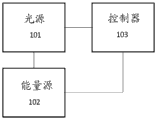
FIG. 1 illustrates an embodiment of a lighting system;
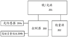
FIG. 2 illustrates another embodiment of a lighting system;
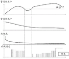
FIG. 3 shows a graph illustrating various light levels and pulses and user alertness levels;
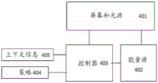
FIG. 4 illustrates another embodiment of a lighting system; and
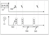
fig. 5 is a timing diagram illustrating the emission of a light pulse.
Detailed Description
Generally, there is provided a lighting system comprising one or more light sources arranged to emit light into an environment. In addition to providing illumination for that environment, at least one of the one or more light sources is arranged to emit a light pulse having a duration of between 1ms and 50ms for making a user located in the environment more alert than they would have been if that pulse had not been emitted, wherein there is an idle period on either side (i.e. on both sides) of the first light pulse lasting at least 0.1 s. The idle period is the time: during which the controller is configured not to cause light pulses having a duration between 1ms and 50ms to be emitted from at least one of the at least one light source. As mentioned, this has the effect of making the user in that environment more alert, which is undesirable because light that is bright over a duration of less than 50ms is generally not considered consciously perceptible to the user. It has been found, however, that such short duration light pulses do have a beneficial effect on the alertness of the user. The idle period ensures that the pulses are actually short, discrete pulses. It can be described as a period of time: where the light emitted by at least one light source is constant, or at least the level of variation in the idle period-if used alone-will have a negligible effect (other than the effect of acting as a separator to ensure that the pulse is isolated) on the level of alertness of users located within the environment of those light sources (in contrast to the effect of acting as a separator to ensure that the pulse is isolated, so that the combined effect of the pulse and the idle period is to keep the user alert). Thus, the idle period is the time: during which the controller is configured not to cause any light pulses having a duration between 1ms and 50ms to be emitted from at least one of the at least one light source.
Additional pulses may be emitted at intervals to "refresh" the state of the user's alertness. For example, a second light pulse having a duration of between 1ms and 50ms may be emitted at least 0.1s after the first pulse has ceased to be emitted. The at least one light source emitting the second pulse may be different from or the same as the at least one light source emitting the earlier light pulse. Which at least one light source emits which pulse may be determined by the controller in various different ways. For example, the light sources may be determined randomly using a predetermined pattern (such as a polling scheduling scheme) or based on information received from the sensors. For example, if a user is working with multiple displays (which is often the case in hospitals, offices and security), the light pulses may be provided using the screen that the user is currently looking at. Another example is where there are multiple application windows on the display screen and attention is to be turned to a particular application window at a particular time. Examples are provided below that relate to when a sensor is used to provide information to a controller (or to a user) for determining when/whether to emit a new light pulse.
The frequency of the pulses may also be determined by the user. It has been found that the pulses act, even if the time difference between successive pulses is large, without the state indicating alertness suddenly disappearing. The large time span between pulses (e.g., on the order of an hour) also makes the applied pulses less noticeable to a user located in the environment. The initial repetition rate of the pulses may be, for example, once every few seconds, so that a user located in that environment is aware of some events/states. Thereafter, once attention has been focused and/or the user has been made more vigilant by the use of the light pulses, the frequency of the light pulses may be reduced in time, e.g., starting with more frequent pulses to bring the person at the correct level of concentration, and reducing the frequency to maintain the level of concentration.
An example lighting system is illustrated in fig. 1. In fig. 1, the lighting system comprises a light source 101 and a controller 103, as described above. According to at least one of the embodiments outlined herein, the controller is configured to transmit an instruction to the light source 101 to inform the light source to emit light. Also shown is an energy source 102. The energy source 102 is depicted as being connected to both the light source 101 and the controller 103. However, it is understood that the energy source 102 may comprise two different sources of energy (such as a battery and a mains supply) or may be a source of only one type of energy (such as a battery or a mains supply). It is also understood that the energy source 102 may be the same energy source for both the controller 103 and the light source 101, or the energy source 102 may be different for the controller 103 and the light source 101.
The light source 101 represents one or more light sources arranged to emit light into the environment. These light sources emit light for a primary reason or function. For example, a display screen may emit light into the environment for viewing the screen, as may be the case with a work light in an office or operating system. In an embodiment, when the at least one or more light sources are projector lights, the primary function may involve providing light for projecting an image onto a display screen. The controller 103 is configured to cause at least one of the light sources to provide an auxiliary function, i.e. to cause a user located within the environment to become more alert. To accomplish this, the controller 103 causes at least one of the light sources 102 to emit at least a first light pulse having a duration of between 1ms and 50 ms. This pulse has the effect of making the user more awake than they would have been had the pulse not been transmitted. To save energy, the pulses are preferably less than 10 ms.
As mentioned above, additional light pulses may be emitted at intervals to "refresh" the state of the user's alertness. For example, a second light pulse having a duration between 1ms and 50ms may be produced at least 0.1s after the stop of the emission of the first pulse. Also as above, the at least one light source emitting the second pulse may be different from or the same as the at least one light source emitting the earlier light pulse.
Preferably, the light pulses are unobtrusive to activities that are performed according to the primary function of the at least one light source. The term "unobtrusive" in this sense includes at least one of the following: light pulses are not apparent to the human visual system, but are subconsciously noticed by the human brain; the light pulses coincide with changes that occur in the activity being performed (e.g., changing TV channels, turning pages of a book/magazine, transitions between slide pages in a presentation, etc.); and the light pulses do not substantially interfere with the illumination source providing the primary functional effect.
The controller may be configured to cause the at least one light source providing the secondary function to emit the first light pulse in response to a determination of user fatigue located in proximity to the at least one light source. The controller may be configured to make a determination that a user located in proximity to the at least one light source is fatigued in response to receiving a report from at least one sensor configured to monitor a status of the user. Details of possible reports and sensors are provided below with reference to a feedback control system.
The controller may be configured to cause the at least one light source providing the secondary function to emit the first light pulses according to a pre-programmed timing scheme. The pre-programmed timing scheme may be linked to the display of information related to a presentation being given in the environment, and the first light pulse is timed to coincide with changes in the presentation slides.
The controller may be configured to cause the at least one light source providing the secondary function to emit the first light pulse in response to an instruction from a user to do so. The user may contact the controller through an appropriate application resident on the electronic device.
The controller may be further configured to cause the at least one light source providing the secondary function to emit a second pulse of light no more than one minute after the first pulse is first emitted.
The controller may be further configured to cause the at least one light source providing the secondary function to emit a second pulse of light one hour after the first pulse is emitted.
The controller may be configured to cause the at least one light source providing the secondary function not to perform the other function.
The controller may be configured to cause the at least one light source providing the secondary function to perform the primary function. The controller may be configured to cause the at least one light source providing the secondary function to superimpose the first light pulse on the primary function.
The primary function may be at least one of the following: lighting of operating rooms, lighting of control rooms, lighting of backlights of displays of devices, lighting of industrial production sites, lighting of devices, lighting in cockpit, lighting of offices, lighting of the interior of automobiles (which may be provided via standalone devices or by devices with other features such as instrument panels), and lighting of headlights of automobiles.
The controller may be further configured to set at least one of an intensity, a color temperature, a pulse duration, and/or a frequency of at least one light source providing the secondary function in response to receiving feedback information from a sensor located in the environment. The controller may be configured to set the intensity of the light pulses such that a higher intensity and/or a higher color temperature of the light and/or a higher frequency of the light pulses is selected when the user is determined to be well below the alertness threshold, but not when the user is determined to be less well below the alertness threshold.
The controller may be remote from or co-located with the at least one light source. The controller may communicate with the at least one light source and/or other controllers via an internal connection, wired or wireless communication interface. Where at least one sensor is used to provide feedback information, as mentioned above and described below, the controller may further communicate with the at least one sensor via an internal connection, wired or wireless communication interface.
The at least one sensor may be a stand-alone sensor (i.e. their sole function is to provide information about the at least one measurable parameter), integrated with the at least one light source 102, part of a user device (including devices emitting light), part of a controller; which communicates via internal connections or wired or wireless communication interfaces with one or more controllers, one or more lights, and where applicable, other sensors in the lighting system. An example sensor includes: cameras, vital signs sensors (worn by the user or contactless) and sensors that measure the output of the user qualitatively or quantitatively (e.g. speed of typing, accuracy of part grinding, number of parts processed on the assembly line of the factory). Feedback from the camera may be used by the controller 103, or by some other such system, to determine the direction in which the light pulses should be emitted from the at least one light source, such that the light pulses are directed towards the eyes of the user to whom the alertness improving effect is targeted.
Specific embodiments will now be described with reference to the accompanying drawings.
In one embodiment, the light source 101 arranged to provide the first light pulse and, where applicable, the second light pulse is a dedicated light source. By this it is meant that the light source 101 providing the first and second pulses does not perform other light emitting functions. This is particularly useful in those cases where the light sources may be configured by the controller to emit light pulses such that they are directed towards the eyes of a user located in the environment. For this effect, the environment may be equipped with sensors. As mentioned above, the sensors may be stand-alone sensors (i.e. their sole function is to provide information about at least one measurable parameter), integrated with the at least one light source 102, part of a user device (including devices emitting light), part of a controller; which communicates via internal connections or wired or wireless communication interfaces with one or more controllers, one or more lights, and where applicable, other sensors in the lighting system. An example sensor includes: cameras, vital signs sensors (worn by the user or contactless) and sensors that measure the output of the user qualitatively or quantitatively (e.g. speed of typing, accuracy of part grinding, number of parts processed on the assembly line of the factory). Feedback from the camera may be used by the controller 103, or by some other such system, to determine the direction in which light pulses should be emitted at the at least one light source to be directed toward the user's eye. Further, the user's location may be determined from the device or tool that the user is currently using, while the direction in which the user is gazing may be determined from an application, program, or window on the display that the user is currently using. The controller 103 may then direct the at least one light source to direct the pulse(s) toward the user's eye. Potential use cases include light sources close to or integrated in the digital dashboard of a control room, light sources integrated into road signs, light sources integrated into the edge of the rear view mirrors of an automobile, and light sources integrated into wearable lighting devices such as augmented reality glasses, backlighting of screens, and displays. Personal display devices, such as augmented reality helmets or glasses, are particularly useful for providing personalized light pulses to a user in an environment. Furthermore, through the use of the personal display device, others in the environment may remain unaffected. This may be useful when only one person in the environment needs to maintain a certain level of alertness (e.g. it would be useful to keep a nurse alert while allowing the patient to rest). Further, the personal display device is easily made movable, and thus the personal display device can accompany the user as the user moves between different environments.
In another embodiment, the light source 101 arranged to provide the first and second light pulses is created by a functional light source. By this it is meant that the light source 101 is arranged to both create the first and second pulses and to perform a further functional effect/provide an alternative purpose. Further functional effects or purposes may be, for example, operating lights in an operating room, cockpit lighting of an airplane, headlights of a car (which will then reflect off road signs, symbols, front cars and other objects) and background lighting of a concert. Integration in functional lighting can be achieved by controlling the same lamps already used to provide this function and superimposing pulses on the functional light. The superimposing may involve stopping the primary illumination function immediately while the light pulse is being performed, or may involve performing both the primary illumination function and the light pulse simultaneously. The primary illumination function and the light pulses may be emitted simultaneously (especially when the primary illumination function is provided in a pulsed manner by a Light Emitting Diode (LED) controlled by the light source using Pulse Width Modulation (PWM)), which interleaves the control signals of the two pulses by placing the light pulses in the inter-pulse spaces of the primary light. Such an arrangement limits peak energy consumption. It will therefore be appreciated that the light pulse may be applied simultaneously with other light in the environment (although subconsciously, as the duration of the light pulse is between 1ms and 50 ms).
The application of the light pulse may be triggered by an event in the environment. For example, the lowering/closing of blinds, activation of dimmed light settings or presentation mode in a conference room, auditorium or concert hall and information about a user located in the environment reach the controller (as described below with respect to feedback) which crosses a predetermined threshold in the controller. The application of the light pulses may be arranged according to some predetermined pattern. For example, the application of the light pulse may be applied or begin to be applied according to the time of day. Furthermore, the application of the light pulses may be triggered by a sensor (e.g. a camera or a vital signs sensor or an output sensor), as mentioned above. Furthermore, the application of light pulses may be triggered by the presence, absence or variation of parameters that may affect the alertness and drowsiness of the user; those parameters include ambient temperature, proximity to sunlight, type of sound background (e.g., presence of relaxing music or low noise), etc. They may be measured by sensors (worn by the user or placed in the environment), or known to the controller by other means.
It is further understood that throughout the above and below, the information provided by the sensor may be presented to an operator of the lighting system, who determines from that information whether, when and where to cause the light pulses to be emitted by the at least one light source.
Because alertness increasing means may take some time to take effect, in some applications it may be beneficial to apply them at least partially before performing a task requiring alertness. For example, a light in a hallway in front of the meeting room or a light in the meeting room may be used prior to the meeting, or a screen in the waiting room for the pilot may be used prior to the pilot's flight. It is thus understood that the application of the light pulses may be started before the start of an activity for which the functional illumination is used (e.g. before an operation in an operating room or before a flight in a cockpit). The light pulses may also be configured to stop being emitted before the end of the activity for which the functional illumination is used. The activation of the function may advantageously be coupled to a schedule/calendar and/or presence detection means, i.e. only applied when a meeting/flight is scheduled and/or a person is present. More intelligent presence detection systems may distinguish the type, role, or task of a person, for example, using facial recognition, uniform recognition, badges, personal devices, and the like. For conferences, the application of light pulses may be a selectable option.
In further embodiments, the system may comprise at least one of: sensor(s), camera(s) and loudspeaker(s) for determining a level of vigilance of a user (or users) located in an environment. These may be used to provide feedback to the controller 103 of the lighting system. Preferably, the sensor(s) are provided when the level of alertness of a particular user in an environment is more important than the level of alertness of other users within that environment. The sensor may be configured to measure and/or determine at least one biometric parameter associated with a user located in the environment. The sensors may be user worn or remote from the user and may include cameras, infrared cameras, magnetic sensors, and the like. Example biometric parameters include those received from stress sensors, heart rate sensors, motion sensors, eye tracking sensors, and the like. The use of cameras and loudspeakers in the environment is most useful when there are a large number of users in the environment, since the status of a large number of users can be determined using limited feedback. Visual information about the user's eye movements received from the camera may be used to determine the alertness of the user in the system. The alertness of a user in the system may be determined using audio information received from the microphone, such as typing noise, speed, yawning or breathing patterns, and reaction times to selected events, e.g., laughter in response to a joke. Any sensor that qualitatively and/or quantitatively measures the user's output (e.g., speed of typing, correctness of typing, precision of part grinding, number of processed parts on the assembly line of the factory, etc.) may be used to determine the alertness of the user in the system.
The feedback information may be used in a closed loop control system in the controller. For example, to assist the controller in a predetermined state intended to maintain alertness of a user located in the environment. The feedback may be used by the controller to control and set any of the frequency of the pulses, the duration of the pulses, the intensity of the pulses (absolute intensity or intensity relative to the light level already in the environment), the light pulse spacing, the light color/spectral composition and the angle of incidence (peripheral versus central viewing) to influence the onset and/or speed of the alertness response or duration in the user. It should be understood that the setting of these parameters may occur in other embodiments described herein, and is not limited to only the present embodiment. The system may be designed such that those parameters are controlled from the application (e.g. based on sensor input) or explicitly by the user of the lighting system. By varying different parameters related to the light pulse(s), the speed and/or duration effect of the alertness increase may be compromised with respect to the perceived disturbance. In one case, it may be acceptable to provide the pilot or surgeon with a short, stressful session, for example, before they begin their flight or surgery. In other cases, a short, intense session may not be acceptable, for example for meeting attendees. Furthermore, the variable parameters can be used to increase alertness slowly and steadily in normal situations (e.g. for night shift workers) or strongly and quickly in alarm situations (e.g. when a fire fighter is awakened at the time of an alarm).
The feedback information may furthermore be used to select at least one light source for providing the pulses. For example, if the user should look at zone a of the screen, but is instead determined to be looking at zone B of the screen (zone B being different from zone a), the controller may select at least one light source from zone B to provide the pulse. In this way, the user's attention may be redirected.
The duration of the pulse may be between 1ms and 50 ms. A preferred value for the pulse width duration is 2ms, as this has been shown to be valid. The pulses may occur periodically or aperiodically (e.g., depending on the programming of the controller). When the controller is configured to receive feedback, the aperiodic situation has particular application, as mentioned above, because information on the receipt back of a user's alertness state can trigger an impulse.
It has been found that a long light pulse of 2ms that is repeated once an hour in an environment has a beneficial effect on a user located in that environment. However, in the embodiments described herein, the pulses may be repeated at smaller intervals, such as on the order of seconds and minutes. In one embodiment, the duration between light pulses is no greater than one minute in accordance with the present disclosure. The duration between these light pulses may also have a minimum value. For example, the controller may be arranged not to cause a subsequent light pulse to be emitted until at least 1s has elapsed.
As mentioned above, one of the possible implementations of the above system is in an automobile. An example manner of implementing the above system in an automobile includes integrating the light sources of the first and second pulses into at least one of: the rear-view mirror of a car, any instrument panel that is frequently controlled by the driver (e.g. speedometer, etc.), and the integration of the light source in the navigation device (whether built-in or external). In the external case, the controller needs a connection to the navigation device to trigger the alertness policy, which may be wired or wireless, e.g. by bluetooth or Wi-Fi. When the controller is part of a navigation device, the navigation device may comprise and/or house sensors for measuring light levels in the car, for example, for measuring the alertness of the user, and/or for connecting to external sensors, for example by bluetooth or Wi-Fi.
In the presently described configuration, the controller is connected to a set of sensors. In particular to a light sensor and a driver alertness sensor. The light sensor measures the amount of light inside and outside the automobile. A alertness sensor is a sensor that measures whether the driver is sufficiently alert or whether he is likely to be drowsy. This information may originate from the driver's physiological vital signs, such as heart rate or body temperature, or from the driver's behavior (whether his eyes are closed, whether the driver's eyes blink very frequently, or whether the driver yawns). This example is shown in fig. 2.
In fig. 2, the illumination system 200 is shown as comprising a mirror 201 comprising a light source for emitting pulses as described above. An energy source 202 and a controller 203 are also provided. The energy source 202 has similar functionality and attributes as the energy source 102 described above. The controller 203 has similar functions and attributes to the controller 103 described above. In addition to the general embodiment described above with respect to fig. 1, fig. 2 also shows two sensors, 204a and 204 b. The sensor 204a is a light sensor and measures the amount of light inside the automobile. The sensor 204b is an alertness sensor for determining a physiological state of the user.
Controller 203 implements logic that determines whether an alertness policy needs to be triggered. This determination may depend on additional factors such as driving speed, time of day, traffic conditions on the road (such as traffic congestion), weather conditions, etc. If it is determined that an alertness strategy is triggered, the controller will sense the amount of light in the car through the sensor for tuning the light level that will be produced by the light sources around the rear view mirror (or any other mirror or control panel the driver is using). Based on this sensed light, the controller will start to drive the light sources around the rear view mirror with a light peak of very short duration at a given frequency. Alternatively, the controller may activate a predefined light pattern at a light source around the rear view mirror. As mentioned above, any parameter of the light pattern may be varied to suit the environment and driver conditions.
The controller 203 is then arranged to monitor whether the output of the driver drowsiness sensor increases and/or whether it remains above a given threshold. According to the programming of the controller, the controller may increase the frequency, intensity, color temperature or duration of the light peak if the driver's alertness does not increase, decrease or fall below a threshold value. If the situation does not improve after a given period of time, the controller may indicate to the driver that(s) he needs to rest, for example by changing the light settings of the light sources to show an emergency. Fig. 3 depicts the potential output of a light source as a function of an input sensor.
In fig. 3, the top graph represents the drowsiness level of the user. The dashed horizontal line in the graph represents a threshold level of drowsiness above which it is desired to keep the user awake. When the controller 203 determines that the drowsiness level of the user is higher than the threshold level, the light illuminance levels inside and outside the automobile are acquired. These light levels are shown in the two graphs immediately below the top graph, respectively. The light levels at these points are acquired and used to determine the setting of at least one pulse to be emitted by the mirror/light source. The bottom graph in fig. 3 illustrates a possible output of mirror light.
In another embodiment of the car, the alertness raising light pulse is a reflection of light emitted by headlights of the car (from the wayside infrastructure). Instead of/in addition to the reflective elements used today (such as those used to distinguish waysides, lanes and traffic instructions), the reflective elements may also be configured to provide high intensity light reflection, i.e. they will be optimized for light concentration and reflection/transmission efficiency. Thus, the light pulse may reflect off the reflective element and back towards the user. Alternatively or in addition, the reflective element may be configured to both emit light and be energy harvesting (via built-in solar cells or vibration harvesters). The new reflective element may also be integrated into a wayside infrastructure with available mains connections, such as street lighting or traffic lights. In order to ensure that an increase in alertness can be effected, the elements can be distributed over a considerable road length, leading to places requiring special attention, such as pedestrian crossings at pubs, intersections, dangerous bends, etc.
Systems similar to those described above may be implemented by placing or integrating light sources around the display of a computer, tablet computer, or electronic book reader. In all those cases, the user is engaged in mental activities. After a certain time of such activity, the user may become fatigued and their concentration level may decrease. Whether the concentration level is reduced can be measured by analyzing vital signs of the user and/or by determining whether his/her eyes tend to close. If such a condition is detected, i.e., if the user is determined to be fatigued, light sources around the display, electronic book reader, or tablet computer may provide pulses of light to the user in accordance with the systems described herein. Alternatively, at least part of the screen itself of those devices may act as a light source and flash with short peaks in order to increase the alertness of the person. Such a system may also provide pulses of light in particular areas of the screen so that the user focuses on important portions of the information for analysis (e.g., when reading, the system may monitor which portion of the text the reader is currently reading and arrange the peak of light from the light source to come primarily from that particular area).
The system in fig. 1 may be used not only to increase the alertness of a person, but also to restrict the use of certain devices or applications in certain circumstances. For example, many people use mobile phones, tablet computers, PCs, game consoles for very long periods of time, and also in any case and at any time. The above-described system may be used to help people to stop using such devices in an excessive manner.
This embodiment is illustrated with respect to lighting system 400 of fig. 4 for controlling the use of applications on certain devices. The illumination system 400 comprises a light source 401, which in this case is a display screen, an energy source 402 and a controller 403. The controller is also configured to receive information from policy engine 404 and context information engine 405. To prevent people from using the smart phone in an excessive way, the policy engine includes a policy for measuring the usage time of the device. When the device has been continuously used for longer than a given time, the controller will then control the light sources around the screen or the screen itself to provide a light effect that hinders the use of the application. This light effect may be: (i) flashing; (ii) low or high light intensity that makes reading more difficult, etc.; (iii) unpleasant light pulses; and (iv) processing by the brain as unpleasant subconscious light signals. The controller 403 may control the light settings based on different contextual information, such as time of use, type of application being used (e.g., use of a web browser at work), location (e.g., use of a smartphone during a meeting), and intensity of use of a particular application (i.e., how much time it is actively spent, e.g., viewing in a particular application window, scrolling, typing, etc.).
The controller 403 may be implemented as an application: which may be controlled only by certain users (such as parents, doctors or companies) who have administrative rights in the application. This ensures that the end user cannot change the settings. In particular, parents may use such applications to educate their children and influence the types of applications/devices they use, making children accustomed to using those devices/applications. Physicians may also apply this technique to people who have become addicted to using devices, such as smart phones, to curtail the use of their devices.
An unpleasant optical signal may also be used in other situations. For example, they may be used to take people out of an area. One example of a situation would be for encouraging people to leave a theater after the movie has finished playing. Another example of a situation would be to use it at the last stop on public transport to get people away faster. In this case, the lighting system may be integrated into the room general lighting, or in the case of a cinema also in the projection system/display.
Such lighting systems may also be implemented outdoors to discourage people from gathering in particular places, such as building entrances. It can prevent people from gathering around the crime scene or illegal witness from forming. It can be used in safety-critical and/or security-critical places (e.g. around power stations, gas stations), in areas with very high crime, or for times of danger (e.g. together with fire or gas leak alarms) to discourage people from staying in this area. This effect may be activated permanently or only at certain times. There may be a limited set of people who can access the settings, e.g. police, municipal officials.
Furthermore, for people who need to stay in this particular area at that particular time (e.g., police, fire brigade, cleaner, security, etc.), this effect may need to be counteracted. This can be achieved, for example, by: special goggles/glasses (dedicated or built-in to protective clothing they may already be wearing, e.g. goggles, helmets) that can counteract this effect, e.g. by polarization or wavelength based filtering. Another approach may be synchronized shutter operation that makes flickering less annoying.
Another aspect of the above system relates to achieving alertness with less energy. In contrast to continuously impinging the user with high intensity light as in the prior art, the present application discloses the use of short, time-spaced pulses of bright light above a more dimmed general/working light for making the user more awake. This system allows a better utilization of the energy. This may be particularly important for battery powered light sources. In such designs, it may be beneficial to separate the electronics and power supply of the two types of light sources (e.g., with standard components for a constant duty/background light, and with special components for a flashlight to manipulate dynamics) to further increase energy consumption and long battery and product life.
Fig. 5 depicts the timing of the light pulses. The length of the pulse 503 has been extended here to make it visible. A pulse duration of 2ms of bright light once per minute is sufficient to produce an increase in the alertness of the user. The controller 103, 203, 403 is configured to generate a trigger 502 from a determination of an environmental state (e.g., a change in an important system parameter in a power plant control room). The generated trigger 502 causes a light pulse 503 to be generated. Furthermore, after a maximum time (indicated as 504 in fig. 5), a new pulse is generated without a system change triggering it (although as shown, the controller may still be configured to generate a trigger signal for causing the light source to emit a pulse). Also shown is a minimum time period 505, which is the minimum time period between the end of one light pulse and the beginning of a new light pulse. This minimum length is particularly important when rapidly changing parameters during unstable operation would otherwise cause frequent flashes.
The embodiments described above are useful both in low light level (or dimmed light) conditions/environments where you cannot have too bright ambient light, e.g. when working with a display (analyzing CT pictures, working with a PC due to reflections and/or lack of contrast) and in medical applications. As an example, an overcast day has a light intensity of less than 300 lux. Preferably, the light intensity of the environment (which will cause the light pulses to enter the environment) is less than 200 lux. The light intensity level of that environment may be higher than 20 lux.
In an embodiment, the light intensity of the secondary function bright light pulses is at least twice the light intensity of the primary function light emitted into the environment, but may rise to 1000 lux and more, such as 6000 lux or 10000 lux. In a preferred embodiment, the light intensity of the secondary function bright light pulse may be related to, or a function of, the function of the light intensity of the primary function light emitted into the environment, and thus vary along with the light intensity of the primary function light.
The applicant hereby discloses in isolation each individual feature described herein and any combination of two or more such features, to the extent that such features or combinations are capable of being carried out based on the present specification as a whole in the light of the common general knowledge of a person skilled in the art, irrespective of whether such features or combinations of features solve any problems disclosed herein, and without limitation to the scope of the claims. The applicant indicates that aspects of the present invention may consist of any such individual feature or combination of features. In view of the foregoing description it will be evident to a person skilled in the art that various modifications may be made within the scope of the invention.
Claims (15)
1. An illumination system, comprising:
one or more light sources (101, 201, 401) arranged to emit light into an environment, at least the one or more light sources (101, 201, 401) being arranged with a primary function comprising providing illumination into the environment; and
a controller (103, 203, 403) configured to cause at least the one or more light sources (101, 201, 401) to provide a secondary function of emitting at least a first light pulse of bright light having a duration of between 1ms and 50ms, wherein there is an idle period lasting at least 0.1s on either side of the first light pulse;
wherein the controller (103, 203, 403) is configured to cause at least the one or more light sources (101, 201, 401) providing the secondary function to emit the first light pulse according to a pre-planned timing scheme; and
wherein at least the one or more light sources (101, 201, 401) arranged with the primary function are arranged to display or project information in the environment, and wherein the pre-planned timing scheme is linked to the displayed or projected information such that the first light pulse is timed to coincide with a visual change in the displayed or projected information.
2. The lighting system of claim 1, wherein the primary function and the secondary function are provided by at least one first light source.
3. The lighting system of claim 1, wherein the primary function is provided by at least one first light source and the secondary function is provided by at least one second light source.
4. The lighting system of any one of claims 1-3, wherein the controller (103, 203, 403) is configured to cause at least the one or more light sources (101, 201, 401) to emit a second light pulse of bright light having a duration of between 1ms and 50ms, the second light pulse being generated at least 0.1s after the first light pulse has stopped being emitted.
5. The lighting system of claim 4, wherein the controller (103, 203, 403) is further configured to determine, with respect to the first light pulse, a time at which the second light pulse should be emitted, depending on an activity to be undertaken by a person located in the environment.
6. A lighting system as claimed in any one of claims 1-3, wherein the controller (103, 203, 403) is configured to cause at least the one or more light sources (101, 201, 401) providing the secondary function to emit the first light pulse in response to a determination that the alertness of a person located in the environment has decreased.
7. The lighting system of claim 6, wherein the controller (103, 203, 403) is configured to make the determination that the alertness of the person located in the environment has decreased in response to receiving a report from at least one sensor configured to monitor a status of the person located in the environment.
8. The lighting system of claim 1, wherein the controller (103, 203, 403) is configured to cause at least the one or more light sources (101, 201, 401) providing the secondary function to emit the first light pulse in response to an instruction from an operator of the lighting system to emit the first light pulse.
9. The lighting system of any one of claims 1-3, wherein the controller is configured to cause at least the one or more light sources (101, 201, 401) providing the secondary function to perform only the secondary function.
10. The lighting system of any one of claims 1-3, wherein the controller (103, 203, 403) is configured to cause at least the one or more light sources providing the secondary function to perform the primary function.
11. The lighting system of claim 4, wherein at least the one or more light sources (101, 201, 401) configured to emit the first light pulse are different from at least the one or more light sources (101, 201, 401) configured to emit the second light pulse.
12. The lighting system of any one of claims 1-3, wherein the controller (103, 203, 403) is further configured to set at least one of an intensity, a pulse duration and/or a frequency of at least the one or more light sources (101, 201, 401) providing the secondary function in response to receiving feedback information from sensors located in the environment.
13. Use of a lighting system as claimed in any preceding claim for making a person located in an environment more alert, wherein the controller causes at least the one or more light sources (101, 201, 401) providing the first light pulse to emit the first light pulse unobtrusively by means of at least one of:
-the first light pulse is not significant to the human visual system of the person,
-the first light pulse coincides with a change in activity of the person, and
-said first light pulses do not substantially disturb said primary function.
14. A method for a controller (103, 203, 403) in a lighting system according to any one of the preceding claims, the lighting system comprising one or more light sources (101, 201, 401) arranged to emit light into an environment, the method comprising:
causing at least the one or more light sources (101, 201, 401) to provide a primary function comprising providing illumination into the environment; and
-causing at least the one or more at least one light source (101, 201, 401) to provide a secondary function of emitting at least a first light pulse of bright light having a duration of between 1ms and 50ms, wherein on either side of the first light pulse there is an idle period lasting at least 0.1 s.
15. A computer-readable medium, having stored thereon a computer program adapted to cause performing of the steps of claim 14, when the computer program is run on a data processing apparatus.
Applications Claiming Priority (3)
| Application Number | Priority Date | Filing Date | Title |
|---|---|---|---|
| EP15161823 | 2015-03-31 | ||
| EP15161823.8 | 2015-03-31 | ||
| PCT/EP2016/057015 WO2016156462A1 (en) | 2015-03-31 | 2016-03-31 | Lighting system and method for improving the alertness of a person |
Publications (2)
| Publication Number | Publication Date |
|---|---|
| CN107889466A CN107889466A (en) | 2018-04-06 |
| CN107889466B true CN107889466B (en) | 2021-01-22 |
Family
ID=52780468
Family Applications (1)
| Application Number | Title | Priority Date | Filing Date |
|---|---|---|---|
| CN201680020900.XA Active CN107889466B (en) | 2015-03-31 | 2016-03-31 | Lighting system and method for improving alertness of a person |
Country Status (5)
| Country | Link |
|---|---|
| US (1) | US10226593B2 (en) |
| EP (1) | EP3277359B1 (en) |
| JP (1) | JP6688549B2 (en) |
| CN (1) | CN107889466B (en) |
| WO (1) | WO2016156462A1 (en) |
Families Citing this family (10)
| Publication number | Priority date | Publication date | Assignee | Title |
|---|---|---|---|---|
| DE212017000225U1 (en) * | 2016-10-03 | 2019-06-27 | Gentex Corporation | Driver identification and authentication systems |
| EP3566548B1 (en) * | 2017-01-04 | 2020-05-13 | Signify Holding B.V. | Adaptive lighting automation |
| FR3065305B1 (en) * | 2017-04-12 | 2020-08-28 | Valeo Vision | BEHAVIORAL DRIVING ASSISTANCE SYSTEM |
| EP3632187B1 (en) | 2017-05-30 | 2021-01-13 | Signify Holding B.V. | Lighting control |
| EP3445138A1 (en) | 2017-08-17 | 2019-02-20 | Philips Lighting Holding B.V. | Storing a preference for a light state of a light source in dependence on an attention shift |
| WO2019176577A1 (en) * | 2018-03-14 | 2019-09-19 | ソニー株式会社 | Information processing device, information processing method, and recording medium |
| CN112930008B (en) * | 2021-01-27 | 2023-06-30 | 恒大新能源汽车投资控股集团有限公司 | Method and system for controlling atmosphere lamp in vehicle |
| IT202100022679A1 (en) * | 2021-09-01 | 2023-03-01 | Relio Labs S R L | HIGH BEAM LIGHTING SYSTEM VEHICLE INSTALLABLE OR OTHERWISE POCKETABLE |
| US11659642B1 (en) | 2021-12-06 | 2023-05-23 | American Sterilizer Company | Surgical lighting system co-illumination detection |
| US20240038055A1 (en) * | 2022-08-01 | 2024-02-01 | Pixart Imaging Inc. | Multi-stage firm alarm device |
Citations (5)
| Publication number | Priority date | Publication date | Assignee | Title |
|---|---|---|---|---|
| KR20110105411A (en) * | 2010-03-19 | 2011-09-27 | 주식회사 헤르메티스 | Safe driving system using remote bio radar sensor |
| CN102448232A (en) * | 2011-12-23 | 2012-05-09 | 中国计量学院 | LED (light-emitting diode) lighting controller with sensitization function |
| CN103136900A (en) * | 2012-11-12 | 2013-06-05 | 祝珍海 | Middle support of driver warning instrument |
| CN103347446A (en) * | 2010-12-10 | 2013-10-09 | Tk控股公司 | System for monitoring a vehicle driver |
| CN103956026A (en) * | 2014-04-04 | 2014-07-30 | 驻马店市金格尔电气设备有限公司 | Fatigue driving warning system based on mobile phone |
Family Cites Families (29)
| Publication number | Priority date | Publication date | Assignee | Title |
|---|---|---|---|---|
| FR2640512B1 (en) * | 1988-12-16 | 1991-03-22 | Martin Joaquim | LIGHTING METHOD, DEVICES AND INSTALLATIONS WITH PSYCHO-PHYSIOLOGICAL EFFECTS, PARTICULARLY AGAINST STRESS |
| DE19952408C2 (en) | 1999-10-29 | 2003-10-30 | Daimler Chrysler Ag | System for warning or prior information of other road users by a vehicle |
| DE10152852A1 (en) | 2001-10-25 | 2003-05-22 | Daimler Chrysler Ag | System for determining and influencing emotional state of motor vehicle driver, has emotion sensors, emotional state assessment device, device for stimulating driver with e.g. visual influences |
| US6974414B2 (en) * | 2002-02-19 | 2005-12-13 | Volvo Technology Corporation | System and method for monitoring and managing driver attention loads |
| JP2006027533A (en) | 2004-07-20 | 2006-02-02 | Toyota Motor Corp | Awakening lighting system |
| JP4561278B2 (en) | 2004-09-24 | 2010-10-13 | パナソニック電工株式会社 | Lighting control system |
| JP4773080B2 (en) | 2004-12-17 | 2011-09-14 | 株式会社デンソー | Visibility improvement support device |
| DE102005059492A1 (en) | 2005-12-13 | 2007-06-14 | Dirk Prof. Dr.-Ing. Jansen | Randomly distributed light pattern generating method for e.g. advertising application, has battery, where random sequences are dimensioned such that light pulse pattern is generated and pattern is unforeseeable for observer |
| CN201117024Y (en) | 2007-06-20 | 2008-09-17 | 何文江 | Daily commodity for using light, odor and sound to awake sleeping people |
| EP2180922A4 (en) * | 2007-08-20 | 2010-09-29 | Univ Laval | Artificial light apparatus and its use for influencing a condition in a subject |
| US8185594B2 (en) | 2008-06-13 | 2012-05-22 | Seiko Epson Corporation | Real-time messaging system for an image display device |
| WO2010070882A1 (en) | 2008-12-16 | 2010-06-24 | パナソニック株式会社 | Information display device and information display method |
| US9333319B2 (en) * | 2009-04-16 | 2016-05-10 | Koninklijke Philips N.V. | Illumination device and method for reducing sleep inertia or controlling alertness |
| US8284631B2 (en) | 2009-12-14 | 2012-10-09 | Tirid Tech Co., Ltd. | Multimedia projection alarm clock with integrated illumination |
| DE102009058459A1 (en) * | 2009-12-16 | 2011-06-22 | Volkswagen AG, 38440 | Method and device for determining a vigilance condition |
| BR112012028880A2 (en) | 2010-05-14 | 2017-12-19 | Koninl Philips Electronics Nv | sleep mask configured to provide light therapy to an individual, method of generating electromagnetic radiation in a first wavelength range and a second wavelength range to release to an individual and system configured to provide light therapy to an individual. an individual. |
| DE202010016309U1 (en) * | 2010-12-07 | 2011-05-05 | Telmed Medizintechnik Gmbh | Apparatus and method for improving mental performance in the event of drowsiness |
| WO2012090111A1 (en) * | 2010-12-31 | 2012-07-05 | Koninklijke Philips Electronics N.V. | Generating light in a vehicle |
| US9333372B2 (en) | 2011-02-20 | 2016-05-10 | James Otis | Methods and apparatus for intermittent stimuli |
| US20130038437A1 (en) | 2011-08-08 | 2013-02-14 | Panasonic Corporation | System for task and notification handling in a connected car |
| JP5694082B2 (en) * | 2011-08-12 | 2015-04-01 | 株式会社東芝 | LIGHTING DEVICE AND INFORMATION PROCESSING DEVICE |
| US8796935B2 (en) | 2011-10-21 | 2014-08-05 | Applied Minds, Llc | Method of regulating blue lighting in command centers |
| WO2013061597A1 (en) * | 2011-10-25 | 2013-05-02 | 学校法人金沢医科大学 | Light exposure device for improving cognitive symptoms and depression symptoms, chamber having light exposure device, and lighting equipment for improving cognitive symptoms and depression symptoms |
| US9235987B2 (en) * | 2011-11-17 | 2016-01-12 | GM Global Technology Operations LLC | System and method for closed-loop driver attention management |
| US9147297B2 (en) * | 2012-03-14 | 2015-09-29 | Flextronics Ap, Llc | Infotainment system based on user profile |
| US8593912B1 (en) | 2012-04-18 | 2013-11-26 | William Amores | Multimedia alarm clock projector |
| WO2014001928A2 (en) * | 2012-06-27 | 2014-01-03 | Koninklijke Philips N.V. | System and method for enhancing alertness. |
| US9636380B2 (en) * | 2013-03-15 | 2017-05-02 | The Board Of Trustees Of The Leland Stanford Junior University | Optogenetic control of inputs to the ventral tegmental area |
| FR2998035A1 (en) * | 2013-05-07 | 2014-05-16 | Continental Automotive France | Lighting device for low definition display of car, has control circuit, where secondary impulse is received during interval of time having duration during which heat produced by on-impulse and by secondary impulse are evacuated by device |
-
2016
- 2016-03-31 US US15/563,777 patent/US10226593B2/en active Active
- 2016-03-31 JP JP2017550845A patent/JP6688549B2/en active Active
- 2016-03-31 EP EP16713429.5A patent/EP3277359B1/en active Active
- 2016-03-31 CN CN201680020900.XA patent/CN107889466B/en active Active
- 2016-03-31 WO PCT/EP2016/057015 patent/WO2016156462A1/en active Application Filing
Patent Citations (5)
| Publication number | Priority date | Publication date | Assignee | Title |
|---|---|---|---|---|
| KR20110105411A (en) * | 2010-03-19 | 2011-09-27 | 주식회사 헤르메티스 | Safe driving system using remote bio radar sensor |
| CN103347446A (en) * | 2010-12-10 | 2013-10-09 | Tk控股公司 | System for monitoring a vehicle driver |
| CN102448232A (en) * | 2011-12-23 | 2012-05-09 | 中国计量学院 | LED (light-emitting diode) lighting controller with sensitization function |
| CN103136900A (en) * | 2012-11-12 | 2013-06-05 | 祝珍海 | Middle support of driver warning instrument |
| CN103956026A (en) * | 2014-04-04 | 2014-07-30 | 驻马店市金格尔电气设备有限公司 | Fatigue driving warning system based on mobile phone |
Also Published As
| Publication number | Publication date |
|---|---|
| US10226593B2 (en) | 2019-03-12 |
| CN107889466A (en) | 2018-04-06 |
| WO2016156462A1 (en) | 2016-10-06 |
| EP3277359A1 (en) | 2018-02-07 |
| JP6688549B2 (en) | 2020-04-28 |
| JP2018511918A (en) | 2018-04-26 |
| US20180078731A1 (en) | 2018-03-22 |
| EP3277359B1 (en) | 2024-01-31 |
Similar Documents
| Publication | Publication Date | Title |
|---|---|---|
| CN107889466B (en) | Lighting system and method for improving alertness of a person | |
| JP7470223B2 (en) | Electronic Glasses | |
| JP6731506B2 (en) | A smart home hazard detector that gives a non-alarm status signal at the right moment | |
| JP7025111B2 (en) | Vanity mirror | |
| US9137878B2 (en) | Dynamic lighting based on activity type | |
| ES2841081T3 (en) | Lighting application for an interactive electronic device | |
| CN104540270A (en) | Intelligent lighting system and intelligent lighting lamp with same | |
| JP6725897B2 (en) | How to determine the right lighting for an activity | |
| WO2012111534A1 (en) | Color adaptive therapeutic light control system | |
| CN105898289B (en) | Intelligent worn device and Intelligent worn device control method | |
| CN110958738B (en) | Electronic device with adaptive lighting system | |
| US9205277B2 (en) | Color adaptive therapeutic light control system | |
| WO2012053308A1 (en) | A system for influencing a state of a user and a method thereof | |
| US20130265169A1 (en) | Eyewear Device Configured To Track Head Movement | |
| CN204272460U (en) | A kind of intelligent illuminating system and there is the Intelligent luminaire of this intelligent illuminating system | |
| KR102043184B1 (en) | Lighting controlling systems using mobile device, and lighting controlling method using the same | |
| RU2781236C1 (en) | Electronic glasses | |
| JP2004125784A (en) | Midnight time zone reporting system and method using low-intensity light | |
| RU2806339C1 (en) | Electronic glasses | |
| RU2721308C2 (en) | Electronic glasses | |
| WO2022078885A1 (en) | System and method for emitting an energizing light inside the cabin of an autonomous driving vehicle | |
| BR102012032859A2 (en) | Electronic device to stimulate alertness and alertness in situations of fatigue, tiredness and sleep |
Legal Events
| Date | Code | Title | Description |
|---|---|---|---|
| PB01 | Publication | ||
| PB01 | Publication | ||
| SE01 | Entry into force of request for substantive examination | ||
| SE01 | Entry into force of request for substantive examination | ||
| GR01 | Patent grant | ||
| GR01 | Patent grant | ||
| CP01 | Change in the name or title of a patent holder | ||
| CP01 | Change in the name or title of a patent holder |
Address after: Eindhoven, the Netherlands Patentee after: Signify Holdings Ltd. Address before: Eindhoven, the Netherlands Patentee before: PHILIPS LIGHTING HOLDING B.V. |