CN107848205B - Method for dry cleaning of additive manufactured boards - Google Patents
Method for dry cleaning of additive manufactured boards Download PDFInfo
- Publication number
- CN107848205B CN107848205B CN201680039719.3A CN201680039719A CN107848205B CN 107848205 B CN107848205 B CN 107848205B CN 201680039719 A CN201680039719 A CN 201680039719A CN 107848205 B CN107848205 B CN 107848205B
- Authority
- CN
- China
- Prior art keywords
- plate
- dry cleaning
- cleaning
- board
- powder
- Prior art date
- Legal status (The legal status is an assumption and is not a legal conclusion. Google has not performed a legal analysis and makes no representation as to the accuracy of the status listed.)
- Active
Links
Images


Classifications
-
- B—PERFORMING OPERATIONS; TRANSPORTING
- B29—WORKING OF PLASTICS; WORKING OF SUBSTANCES IN A PLASTIC STATE IN GENERAL
- B29C—SHAPING OR JOINING OF PLASTICS; SHAPING OF MATERIAL IN A PLASTIC STATE, NOT OTHERWISE PROVIDED FOR; AFTER-TREATMENT OF THE SHAPED PRODUCTS, e.g. REPAIRING
- B29C64/00—Additive manufacturing, i.e. manufacturing of three-dimensional [3D] objects by additive deposition, additive agglomeration or additive layering, e.g. by 3D printing, stereolithography or selective laser sintering
- B29C64/30—Auxiliary operations or equipment
- B29C64/35—Cleaning
-
- B—PERFORMING OPERATIONS; TRANSPORTING
- B08—CLEANING
- B08B—CLEANING IN GENERAL; PREVENTION OF FOULING IN GENERAL
- B08B7/00—Cleaning by methods not provided for in a single other subclass or a single group in this subclass
- B08B7/02—Cleaning by methods not provided for in a single other subclass or a single group in this subclass by distortion, beating, or vibration of the surface to be cleaned
-
- B—PERFORMING OPERATIONS; TRANSPORTING
- B08—CLEANING
- B08B—CLEANING IN GENERAL; PREVENTION OF FOULING IN GENERAL
- B08B3/00—Cleaning by methods involving the use or presence of liquid or steam
- B08B3/04—Cleaning involving contact with liquid
- B08B3/10—Cleaning involving contact with liquid with additional treatment of the liquid or of the object being cleaned, e.g. by heat, by electricity or by vibration
- B08B3/12—Cleaning involving contact with liquid with additional treatment of the liquid or of the object being cleaned, e.g. by heat, by electricity or by vibration by sonic or ultrasonic vibrations
- B08B3/123—Cleaning travelling work, e.g. webs, articles on a conveyor
-
- B—PERFORMING OPERATIONS; TRANSPORTING
- B08—CLEANING
- B08B—CLEANING IN GENERAL; PREVENTION OF FOULING IN GENERAL
- B08B5/00—Cleaning by methods involving the use of air flow or gas flow
- B08B5/04—Cleaning by suction, with or without auxiliary action
- B08B5/043—Cleaning travelling work
- B08B5/046—Cleaning moving webs
-
- B—PERFORMING OPERATIONS; TRANSPORTING
- B08—CLEANING
- B08B—CLEANING IN GENERAL; PREVENTION OF FOULING IN GENERAL
- B08B7/00—Cleaning by methods not provided for in a single other subclass or a single group in this subclass
- B08B7/02—Cleaning by methods not provided for in a single other subclass or a single group in this subclass by distortion, beating, or vibration of the surface to be cleaned
- B08B7/026—Using sound waves
- B08B7/028—Using ultrasounds
-
- B—PERFORMING OPERATIONS; TRANSPORTING
- B08—CLEANING
- B08B—CLEANING IN GENERAL; PREVENTION OF FOULING IN GENERAL
- B08B7/00—Cleaning by methods not provided for in a single other subclass or a single group in this subclass
- B08B7/04—Cleaning by methods not provided for in a single other subclass or a single group in this subclass by a combination of operations
-
- B—PERFORMING OPERATIONS; TRANSPORTING
- B29—WORKING OF PLASTICS; WORKING OF SUBSTANCES IN A PLASTIC STATE IN GENERAL
- B29C—SHAPING OR JOINING OF PLASTICS; SHAPING OF MATERIAL IN A PLASTIC STATE, NOT OTHERWISE PROVIDED FOR; AFTER-TREATMENT OF THE SHAPED PRODUCTS, e.g. REPAIRING
- B29C64/00—Additive manufacturing, i.e. manufacturing of three-dimensional [3D] objects by additive deposition, additive agglomeration or additive layering, e.g. by 3D printing, stereolithography or selective laser sintering
- B29C64/10—Processes of additive manufacturing
- B29C64/141—Processes of additive manufacturing using only solid materials
- B29C64/153—Processes of additive manufacturing using only solid materials using layers of powder being selectively joined, e.g. by selective laser sintering or melting
-
- B—PERFORMING OPERATIONS; TRANSPORTING
- B29—WORKING OF PLASTICS; WORKING OF SUBSTANCES IN A PLASTIC STATE IN GENERAL
- B29C—SHAPING OR JOINING OF PLASTICS; SHAPING OF MATERIAL IN A PLASTIC STATE, NOT OTHERWISE PROVIDED FOR; AFTER-TREATMENT OF THE SHAPED PRODUCTS, e.g. REPAIRING
- B29C64/00—Additive manufacturing, i.e. manufacturing of three-dimensional [3D] objects by additive deposition, additive agglomeration or additive layering, e.g. by 3D printing, stereolithography or selective laser sintering
- B29C64/20—Apparatus for additive manufacturing; Details thereof or accessories therefor
- B29C64/245—Platforms or substrates
-
- B—PERFORMING OPERATIONS; TRANSPORTING
- B29—WORKING OF PLASTICS; WORKING OF SUBSTANCES IN A PLASTIC STATE IN GENERAL
- B29C—SHAPING OR JOINING OF PLASTICS; SHAPING OF MATERIAL IN A PLASTIC STATE, NOT OTHERWISE PROVIDED FOR; AFTER-TREATMENT OF THE SHAPED PRODUCTS, e.g. REPAIRING
- B29C64/00—Additive manufacturing, i.e. manufacturing of three-dimensional [3D] objects by additive deposition, additive agglomeration or additive layering, e.g. by 3D printing, stereolithography or selective laser sintering
- B29C64/30—Auxiliary operations or equipment
- B29C64/357—Recycling
-
- B—PERFORMING OPERATIONS; TRANSPORTING
- B29—WORKING OF PLASTICS; WORKING OF SUBSTANCES IN A PLASTIC STATE IN GENERAL
- B29C—SHAPING OR JOINING OF PLASTICS; SHAPING OF MATERIAL IN A PLASTIC STATE, NOT OTHERWISE PROVIDED FOR; AFTER-TREATMENT OF THE SHAPED PRODUCTS, e.g. REPAIRING
- B29C64/00—Additive manufacturing, i.e. manufacturing of three-dimensional [3D] objects by additive deposition, additive agglomeration or additive layering, e.g. by 3D printing, stereolithography or selective laser sintering
- B29C64/30—Auxiliary operations or equipment
- B29C64/386—Data acquisition or data processing for additive manufacturing
- B29C64/393—Data acquisition or data processing for additive manufacturing for controlling or regulating additive manufacturing processes
-
- B—PERFORMING OPERATIONS; TRANSPORTING
- B29—WORKING OF PLASTICS; WORKING OF SUBSTANCES IN A PLASTIC STATE IN GENERAL
- B29C—SHAPING OR JOINING OF PLASTICS; SHAPING OF MATERIAL IN A PLASTIC STATE, NOT OTHERWISE PROVIDED FOR; AFTER-TREATMENT OF THE SHAPED PRODUCTS, e.g. REPAIRING
- B29C67/00—Shaping techniques not covered by groups B29C39/00 - B29C65/00, B29C70/00 or B29C73/00
- B29C67/0033—Shaping techniques not covered by groups B29C39/00 - B29C65/00, B29C70/00 or B29C73/00 by shock-waves
-
- B—PERFORMING OPERATIONS; TRANSPORTING
- B33—ADDITIVE MANUFACTURING TECHNOLOGY
- B33Y—ADDITIVE MANUFACTURING, i.e. MANUFACTURING OF THREE-DIMENSIONAL [3-D] OBJECTS BY ADDITIVE DEPOSITION, ADDITIVE AGGLOMERATION OR ADDITIVE LAYERING, e.g. BY 3-D PRINTING, STEREOLITHOGRAPHY OR SELECTIVE LASER SINTERING
- B33Y30/00—Apparatus for additive manufacturing; Details thereof or accessories therefor
-
- B—PERFORMING OPERATIONS; TRANSPORTING
- B33—ADDITIVE MANUFACTURING TECHNOLOGY
- B33Y—ADDITIVE MANUFACTURING, i.e. MANUFACTURING OF THREE-DIMENSIONAL [3-D] OBJECTS BY ADDITIVE DEPOSITION, ADDITIVE AGGLOMERATION OR ADDITIVE LAYERING, e.g. BY 3-D PRINTING, STEREOLITHOGRAPHY OR SELECTIVE LASER SINTERING
- B33Y40/00—Auxiliary operations or equipment, e.g. for material handling
- B33Y40/20—Post-treatment, e.g. curing, coating or polishing
-
- B—PERFORMING OPERATIONS; TRANSPORTING
- B33—ADDITIVE MANUFACTURING TECHNOLOGY
- B33Y—ADDITIVE MANUFACTURING, i.e. MANUFACTURING OF THREE-DIMENSIONAL [3-D] OBJECTS BY ADDITIVE DEPOSITION, ADDITIVE AGGLOMERATION OR ADDITIVE LAYERING, e.g. BY 3-D PRINTING, STEREOLITHOGRAPHY OR SELECTIVE LASER SINTERING
- B33Y50/00—Data acquisition or data processing for additive manufacturing
- B33Y50/02—Data acquisition or data processing for additive manufacturing for controlling or regulating additive manufacturing processes
-
- B—PERFORMING OPERATIONS; TRANSPORTING
- B29—WORKING OF PLASTICS; WORKING OF SUBSTANCES IN A PLASTIC STATE IN GENERAL
- B29K—INDEXING SCHEME ASSOCIATED WITH SUBCLASSES B29B, B29C OR B29D, RELATING TO MOULDING MATERIALS OR TO MATERIALS FOR MOULDS, REINFORCEMENTS, FILLERS OR PREFORMED PARTS, e.g. INSERTS
- B29K2105/00—Condition, form or state of moulded material or of the material to be shaped
- B29K2105/25—Solid
- B29K2105/251—Particles, powder or granules
-
- Y—GENERAL TAGGING OF NEW TECHNOLOGICAL DEVELOPMENTS; GENERAL TAGGING OF CROSS-SECTIONAL TECHNOLOGIES SPANNING OVER SEVERAL SECTIONS OF THE IPC; TECHNICAL SUBJECTS COVERED BY FORMER USPC CROSS-REFERENCE ART COLLECTIONS [XRACs] AND DIGESTS
- Y02—TECHNOLOGIES OR APPLICATIONS FOR MITIGATION OR ADAPTATION AGAINST CLIMATE CHANGE
- Y02P—CLIMATE CHANGE MITIGATION TECHNOLOGIES IN THE PRODUCTION OR PROCESSING OF GOODS
- Y02P10/00—Technologies related to metal processing
- Y02P10/25—Process efficiency
Abstract
The present invention relates to a method for dry cleaning of a board (10) used in powder based additive manufacturing, the method comprising separating unsolidified powder (16) from the board (10) and collecting unsolidified powder (16). The method comprises the steps of applying vibrations to the plate (10) and transmitting impacts to the plate (10).
Description
Technical Field
The present invention is in the field of additive manufacturing based on powders by sintering or melting particles of said powders using energy beams (e.g. laser beams) and/or particle beams (e.g. electron beams) involving electromagnetic radiation.
More particularly, the present invention relates to the cleaning of additive manufactured boards and components manufactured on these boards.
Background
When performing an additive manufacturing process in an additive manufacturing machine, a first powder layer is deposited on an additive manufacturing plate mounted to be slidable within a housing surrounding the manufacturing plate. This first powder layer is then solidified according to a predetermined design using one of the energy beams described above. The fabrication plate is then lowered within the housing to allow the second powder layer to deposit and solidify. Finally, the steps of lowering the plate and then depositing and solidifying the powder layers continue in turn until the last powder layer required in the manufacture of the assembly to be produced has been deposited and solidified.
One disadvantage encountered at the end of the additive manufacturing process is that the manufactured component or components are themselves immersed in the bulk of the unsolidified powder that needs to be removed.
According to one method, the production plate (with or without casing) is removed from the machine and the operator uses tools (such as brushes and compressed air blowers or suction fans) to wash the powder particles by hand.
Due to its substantially manual nature, this first cleaning method is practically not compatible with industrial applications.
Furthermore, this manual cleaning can be dangerous for the operator, as the powders used in additive manufacturing often contain toxic compounds that may still be inhaled by the operator despite the operator wearing protective equipment.
Finally, according to another drawback, if the unsolidified powder is kept under a protective atmosphere during the cleaning process, it must undergo various treatment operations before being reused.
For this reason, some manufacturers of additive manufacturing machines have modified their machines to better protect the health of the operator and to be able to immediately reuse the cleaned powder from the manufactured component.
For example, the additive manufacturing machine described in european patent EP1793979 is equipped with means allowing an operator to handle and clean the manufacturing parts in the machine manufacturing enclosure.
More specifically, these devices include an opening formed in a wall of a manufacturing enclosure, a robotic arm mounted in the manufacturing enclosure, and a suction tube operable in the manufacturing enclosure. Furthermore, the opening is fitted with protective gloves to allow the operator to reach his hands into the manufacturing enclosure in order to clean the manufactured components using suction tubes, and the operator can control the robotic arm from outside the machine to move the heavy components more easily.
Thanks to the device described in european patent EP1793979, the operator is protected and the unsolidified powder is kept under a protective atmosphere.
However, cleaning is still a manual operation requiring operator work, since the manual cleaning is performed within the machine manufacturing enclosure, the machine cannot be used to manufacture other components during the duration of the cleaning.
Thus, european patent EP1192040 proposes to manufacture components in removable containers that can be removed from the manufacturing enclosure of an additive manufacturing machine and brought to a washing apparatus separate from the machine.
In a first embodiment of the cleaning device, a lid provided with two openings facing each other is arranged on top of the container, and a source of compressed air is connected to the first opening and a reservoir is connected to the second opening. Thus, by gradually raising the manufacturing plate and the manufactured assembly towards the top of the container, the flow of compressed air pushes the unsolidified powder towards the second opening thus into the reservoir.
According to a drawback of this first embodiment, there is a risk of contamination of the powder due to the flow of compressed air pushing the powder towards the reservoir.
In a second embodiment, the top of the container is fitted with an expanding neck comprising a spout to allow the removal of the unsolidified powder when the container is tilted using a suitable device and when the manufacturing plate is gradually raised.
In this second embodiment, the unsolidified powder is advantageously moved to the reservoir under the influence of gravity. Then, since the reservoir is equipped with a screen capable of capturing the manufactured assembly, vibration is used to complete the separation of the powder particles from the manufactured assembly.
Although the cleaning device of this second embodiment does not use a flow of compressed air that easily contaminates the unsolidified powder, it does not allow for perfect cleaning of the manufactured assembly.
In particular, under the action of the vibrations, the finest powder particles tend to float in the air in the form of a cloud, depositing again on the component being manufactured once the vibrations have ceased.
Furthermore, where the components being manufactured have complex shapes and have cavities that easily contain accumulated powder, the use of vibration alone is not sufficient to break up the powder lumps formed in these cavities during additive manufacturing.
Finally, simply using vibration does not allow to remove all the powder particles bound to the manufactured component to the extent of, for example, manual brushing.
Disclosure of Invention
For this reason, the object of the present invention is to overcome at least one of the drawbacks of the devices described in the prior art documents, while allowing to clean the manufacturing plate alone or together with the components that are manufactured on the plate and remain adhered to the plate at the end of the additive manufacturing cycle.
To this end, the subject of the invention is a dry-cleaning method of a plate used in additive manufacturing using powder, said method comprising the steps of separating unsolidified powder from the plate and collecting unsolidified powder, and said method comprising the step of exerting a vibration on the plate and causing the plate to undergo an impact.
By applying an impact to the plate, the powder cake that tends to form in the cavity of the manufactured component is broken up, and by applying a vibration, the majority of the particles of the unsolidified powder gradually detach from the manufactured component and the manufacturing plate, falling under the action of gravity from the plate or the manufactured component.
Preferably, the impact is applied in a direction perpendicular to the plane of the plate, while the vibration is applied in a direction substantially parallel to the plane of the plate.
The vibration step and the impact step may be alternated a number of times in order to clean as completely as possible.
To reduce the cleaning time, the vibration step and the impact step may be performed simultaneously.
In order to make optimum use of the gravitational effect of the unsolidified powder particles during the cleaning process, the method may comprise a preliminary step of inverting the plate.
In order to cause the unsolidified powder particles deposited in the hollow part of the manufactured assembly to fall, the inclination of the plate may be changed during the vibration step and/or the impact step.
In order to protect the operator from the toxicity of certain products used in additive manufacturing, the cleaning process is preferably performed in a doubly confined volume, the cleaning being performed in a cleaning enclosure which is itself within a confinement enclosure.
In view of recovering or storing the powders originating from the washing, the method also comprises a subsequent step of removing the powders from these confined volumes under the action of gravity, preferably by means of suction.
In order to protect the operator and avoid the formation of powder clouds during cleaning, the above-mentioned confined volume is subjected to additional suction during cleaning.
Drawings
Other features and advantages of the present invention will become apparent from the following description. This description, provided by way of non-limiting example, relates to the accompanying drawings, in which:
FIG. 1 is a schematic view of an additive manufacturing plate to be cleaned, said plate being equipped with supports and sleeves,
FIG. 2 is a top view of a cleaning plant according to a first embodiment of the invention, the arrows showing the plate cleaning cycle,
FIG. 3 is a top view of a cleaning installation according to a first embodiment of the invention, the arrows showing the use of the installation according to the invention for supplying cleaned and/or new boards to an additive manufacturing plant,
FIG. 4 is a top view of a cleaning plant according to a second embodiment of the invention, the arrows showing the plate cleaning cycle, and the use of the plant according to the invention for supplying an additive manufacturing plant with cleaned and/or new plates,
figure 5 is a top view of the dry cleaning apparatus according to the present invention,
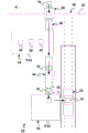
figure 6 is a front view of the dry cleaning apparatus according to the invention, also showing the dry cleaning apparatus receiving the additive manufacturing board to be cleaned,
FIG. 7 is a detail view of FIG. 6, which also shows the arrival of the board to be cleaned at the cleaning housing of the dry-cleaning apparatus,
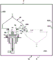
FIG. 8 is a side view of the cleaning casing of the dry cleaning apparatus according to the invention, showing also the turning over of the plate to be cleaned provided by the invention, and
fig. 9 is also a side view of the cleaning housing of the dry cleaning apparatus according to the invention, but this figure shows more particularly the cleaning of the panel to be cleaned by means of the dry cleaning apparatus according to the invention.
Detailed Description
The present invention relates to cleaning of an additive manufacturing board 10.
The additive manufacturing plate 10 takes the form of a parallelepiped support, typically made of metal, having a height of several centimeters and a length and width of tens of centimeters in the plane P10.
As is known, the plate 10 serves as a support in the preparation of components manufactured within a manufacturing chamber of an additive manufacturing machine. More specifically, the plate is mounted within a manufacturing enclosure surrounding the plate in the manufacturing chamber, and the plate is mounted so as to be movable in vertical translation within the manufacturing enclosure so as to be able to lower and then further deposit each layer of unsolidified powder.
As shown in fig. 1, in the context of the present invention, the plate 10 is preferably surrounded by a sleeve 12, said sleeve 12 acting as a manufacturing enclosure within an additive manufacturing machine.
The plate 10 and the sleeve 12 form, by being assembled to each other, a container 15. The container 15 is removably mounted within an additive manufacturing machine so that the container 15 can be removed from the manufacturing cavity of the machine together with the manufactured component 14 and the unsolidified powder 16 surrounding the component 14.
Advantageously, this container 15 makes it easier for the manufactured component 14 and the unsolidified powder 16 to be transported from the additive manufacturing machine to another device present in the additive manufacturing plant or to a cleaning facility (such as the cleaning facility proposed by the present invention).
The plate 10 is equipped with supports 13 for guiding and automatic transport purposes. This support 13 takes the form of a frame on which the production panel 10 is fitted. In order to be held in place by means of bolts or other types of retractable pins, the support 13 comprises holes 17. Finally, this support 13 is fitted with a peripheral sealing gasket 19, so as to avoid any powder leakage when the plate 10 and its support 13 move in translation inside the sleeve 12.
A key objective of the present invention is to recover (without adversely affecting) the bulk of the unsolidified powder 16 surrounding the component 14 in the container 15 and to make the manufactured component 14 and additive manufacturing board 10 as free as possible of the particles of the unsolidified powder.
To this end, the present invention provides an additive manufacturing panel cleaning facility 20 as shown in fig. 2.
The installation 20 comprises an entry lock 22 and a suitable transport device 24, the entry lock 22 being capable of receiving a panel 10 to be cleaned from an additive manufacturing machine, the transport device 24 being arranged to transport the container 15, the manufactured component 14 and the unsolidified powder 16 from the additive manufacturing machine to the entry lock 22 of the installation under the best conditions possible.
To enable removal of the cleaned panel 10 from the facility, the facility 20 also includes an exit lock 26. Since the facility 20 as a whole is preferably confined within a protective enclosure 28 partially shown in fig. 2-4, the exit lock 26 is formed through a wall 30 of the enclosure 28.
As indicated by the various arrows of fig. 3, the exit lock 26 may also supply the facility 20 with new and/or cleaned boards 10 from the exterior E of the facility, and the entry lock 22 may also be used to remove cleaned boards 10 from the cleaning facility 20 to bring the boards to the additive manufacturing machine via the transport device 24.
In order to ensure an optimal cleaning of the panels 10, the installation 20 comprises a dry cleaning device 32, a wet cleaning device 34 and at least one transport device, said dry cleaning device 32 allowing the panels 10 to be cleaned using vibrations and impacts in a first confinement enclosure E32, said wet cleaning device 34 allowing the panels 10 to be cleaned using at least one liquid in a second confinement enclosure E34, said transport device allowing the transport of the panels 10 between the dry cleaning enclosure E32, the wet cleaning enclosure E34 and the exit lock 26 of the installation.
More specifically, the dry cleaning apparatus 32 is intended to recover the maximum quantity of unsolidified powder without adversely affecting the powder, and therefore to reuse it as quickly as possible, without the need for a preliminary drying treatment but only the need for screening, the purpose of which is to keep control of the particle size distribution of the powder thus recovered. The wet cleaning equipment 34 is then intended to perfectly clean the manufactured assembly 14 and the manufactured panel 10 by removing all the unsolidified powder particles that remain adhered to the assembly and panel after the dry cleaning.
In order to obtain a perfect cleaning of the manufactured assembly 14 and of the manufactured board 10, the wet cleaning device 34 comprises, inside its housing E34, at least one cleaning station 38 and at least one rinsing station 40, said cleaning station 38 cleaning the board 10 with a cleaning liquid and said rinsing station 40 rinsing the board 10 with a rinsing liquid.
Preferably, the washing station 38 takes the form of a tank filled with washing liquid and equipped with means (for example transducers) allowing the emission of very high frequency ultrasound waves (preferably 20kHz, possibly 45kHz) towards the washing liquid. Thus, when the plate 10 and the assembly 14 to be cleaned are immersed in the cleaning liquid, the ultrasonic waves generate, through the cavitation phenomenon, micro-bubbles which implode under the action of the same waves, these implosions generating turbulence in the cleaning liquid and allowing the eventual powder particles still bound to the manufactured assembly 14 and to the manufactured plate 10 thereof to become detached. Advantageously, the small size of the bubbles allows the bubbles to enter the smallest cavity in the manufactured assembly 14.
Ideally, the cleaning liquid is an aqueous solution and the rinsing liquid is also an aqueous solution.
In order to make the washing step easier and to improve the washing quality achieved, the wet-washing device 34 may comprise, inside its housing E34, a pre-washing station 42, said pre-washing station 42 being obviously arranged upstream of the washing station 38.
This pre-wash station 42 may take the form of a tank filled with a pre-wash liquid and the pre-wash liquid is preferably an aqueous solution.
The rinse station 40 may also serve as a drying station and include means for drying the cleaned board and the fabricated assembly 14; these drying means are for example in the form of a trough equipped with a hot air blower.
In view of the complete automation of the installation, the wet-cleaning device 34 comprises, inside its housing E34, conveying means (not shown) which allow to convey in an automated manner the plates 10 to be cleaned and the manufactured assemblies 14 attached to these plates 10 between the various pre-cleaning stations 42, the cleaning station 38 and the rinsing station 40.
In an alternative form of embodiment not shown in the figures, the wet-washing device 34 may comprise a single working chamber, in which the board 10 may be pre-washed, washed and possibly dried, and respective storage chambers for storing the board 10 before, during and/or after these respective steps.
As shown in FIG. 3, the conveyor of the wet scrubbing apparatus 34 also allows for the transport of new and/or cleaned boards 10 through the enclosure E34 of the wet scrubbing apparatus 34 without passing through the various cleaning and rinsing stations.
In a first embodiment of the installation (which is shown in fig. 2 and 3), the installation comprises a first conveyor 44 and a second conveyor 46, said first conveyor 44 allowing the transport of the plates 10 during the washing from the enclosure E32 of the dry cleaning apparatus 32 towards the enclosure E34 of the wet cleaning apparatus 34, said second conveyor 46 allowing the transport of the washed plates 10 from the enclosure E34 of the wet cleaning apparatus 34 towards the exit lock 26 of the installation 20.
The second conveyor 46 also allows for transporting the boards 10 from the exit lock 26 of the facility 20 towards the enclosure E34 of the wet cleaning apparatus 34, and the first conveyor 44 also allows for transporting the boards 10 from the enclosure E34 of the wet cleaning apparatus 34 towards the enclosure E32 of the dry cleaning apparatus 32, in view of introducing new and/or cleaned boards 10 to the additive manufacturing plant through the cleaning facility 20 using the facility's exit lock 26.
When the facility 20 is used in this manner to supply an additive manufacturing plant with new and/or cleaned boards 10, it may be proposed to subject these boards 10 to wet cleaning in a wet cleaning apparatus 34. This ensures that the boards 10 have been perfectly cleaned and decontaminated before use in the additive manufacturing machine, it being possible for the boards 10 to become contaminated outside E of the enclosure 28 of the facility 20 during unprotected storage or during human handling.
In this first embodiment of the facility 20, the two conveyors 44, 46 may be belt conveyors.
In a second embodiment of the installation 20, which is shown in fig. 4, the installation comprises a conveyor 36, at least one storage area 48, 50 and an operating arm 52, said conveyor 36 allowing plates 10 to be transported from the housing E32 of the dry cleaning apparatus 32 towards the exit lock 26 and vice versa from the exit lock 26 towards the housing E32 of the dry cleaning apparatus 32, said storage areas 48, 50 being used for temporary storage of the plates 10, said operating arm 52 allowing the plates 10 to be moved between the dry cleaning apparatus 32, the wet cleaning apparatus 34, the conveyor 36 and each temporary storage area 48, 50.
More specifically, conveyor 36 may be a belt conveyor, each storage area 48, 50 may take the form of an open storage device (e.g., a rack), and operating arm 52 is an articulated arm with a device 54 (e.g., a gripper) mounted at an end thereof for gripping plate 10.
Due to the presence of at least one storage area 48, 50, the handling arm 52 is able to manage, for example, the steps of dry-cleaning and wet-cleaning the respective boards 10 while transporting the cleaned boards 10 from the exit lock 26 to the dry-cleaning apparatus 32 using the conveyor 36.
Preferably, there are two temporary storage areas 48 and 50, so that the cleaned plate 10 and the plate 10 in the cleaning process do not need to be stored in the same area.
It is also preferred that the operating arm 52 be capable of rotational movement about various horizontal and/or vertical axes so as to move each plate 10 from one point to another as quickly as possible.
According to a not shown and more economical alternative of this second embodiment, the operating arm 52 can be omitted and the conveyor 36 can be arranged to carry out the transport of the panels 10 individually between the dry cleaning enclosure E32, the wet cleaning enclosure E34 and the exit lock 26 of the installation.
In order to perform dry cleaning of the board 10 using impact and vibration, the present invention proposes a dry cleaning apparatus 32 of the board 10.
As previously mentioned, the dry cleaning apparatus 32 includes a confinement enclosure E32. For receiving the plate 10 to be cleaned, the confinement enclosure E32 comprises at least one entrance lock 56, and for discharging the cleaned plate 10, the confinement enclosure E32 further comprises an exit lock 58. Advantageously, the entry lock 56 of the casing E32 of the dry cleaning apparatus 32 is also the entry lock 22 of the installation 20.
Since the dry cleaning enclosure E32 is formed on the floor S by the front wall 60F, the rear wall 60R, the left side wall 62G, the right side wall 62D and the ceiling P, the entrance lock 56 is formed through the rear wall 60R of the dry cleaning enclosure E32, and the exit lock 58 is formed through the right side wall 62D of the dry cleaning enclosure E32.
As shown in fig. 5, inside the confinement enclosure E32, the dry-cleaning apparatus 32 comprises a receiving device 64 for receiving the board 10 to be cleaned, and a dry-cleaning station 66 for dry-cleaning the board.
More specifically, the receiving means 64 are able to receive and transport the container 15 formed by the plate 10 to be cleaned, its support 13 and its sleeve 12.
These receiving means 64 take the form of, for example, a chain conveyor 72. The chain conveyor 72 extends horizontally within the dry cleaning housing E32 and in a longitudinal direction DL parallel to the plane of the side walls 62G, 62D of the housing E32 and perpendicular to the front wall 60F and the rear wall 60R of the housing. The chain conveyor 72 thus allows the containers 15, and therefore the panels 10 to be cleaned, to be transported from the entry lock 56 of the casing E32 to the dry cleaning station 66.
In order to make it easier to recover the unsolidified powder 16 contained in the container 15, the dry cleaning apparatus 32 comprises a second cleaning enclosure 68 located inside its first confinement enclosure E32.
The second cleaning housing 68 is in the form of a bell 70 mounted on a base 74, and the base 74 includes an opening 76 to receive the panel 10 to be cleaned.
More specifically, base 74 is substantially flat and rectangular, while bell 70 has a pyramidal S70 shape extending about a central axis a70 perpendicular to a plane P74 of base 74. At the same time, the shape and size of the opening 76 is or can be adjusted to suit the shape and size of the panel 10 to be cleaned.
The pyramidal shape of the bell 70 about its central axis a70 makes it easier for the unsolidified powder 16 to flow and recover when the bell 70 is inverted with the board 10 to be cleaned.
In a preferred alternative form of embodiment shown in fig. 6 to 9, the bell 70 comprises a bottom 70B and a top 70H, said bottom 70B being parallelepiped-shaped about its central axis a70, said top 70H being pyramid-shaped about its central axis a70, the parallelepiped-shaped bottom 70B extending from the base 74 and the pyramid-shaped top 70H extending between this bottom 70B and the apex 78 of the bell 70.
In another alternative, the bell may also assume a fully pyramidal shape, a partially or fully conical shape, a partially or fully frustoconical shape, or any other shape capable of forming a funnel when the bell 70 is inverted.
To control the flow of the unsolidified powder 16 when the bell 70 is inverted so that its base 74 is above its apex 78 (as shown in fig. 8 and 9), the apex 78 of the bell 70 takes the form of a tube 80 fitted with a valve 82 or any other flow regulating device.
As mentioned above, the invention proposes to invert the bell 70 and the plate 10 so that the unsolidified powder 16 surrounding one or more manufactured assemblies 14 can be recycled to the container 15.
However, it is first necessary to bring the container 15 comprising the plate 10 to be cleaned and the unsolidified powder 16 to be recovered to the opening 76 of the base 74 of the cleaning housing 68.
To achieve this, it is proposed that the cleaning housing 68 is in an initial position corresponding to a non-inverted position in which the bell 70 and its apex 78 are above the base 74. In this initial position of the cleaning housing 68, the plane P74 of the base 74 is substantially horizontal, as shown in fig. 6 and 7.
Thereafter, when the wash enclosure 68 is in its home position, the receiving means 64 allows the container 15 and the board 10 to be transported from the access lock 56 of the confinement enclosure E32 to opposite the opening 76 of the base 74 of the wash enclosure 68.
To supplement the receiving means 64, the dry cleaning apparatus 32 comprises an elevator 84, said elevator 84 allowing to transport the board 10 to be cleaned from the receiving means 64 to the opening 76.
For this purpose and as shown in fig. 6 and 7, the elevator 84 allows the plate 10 to be cleaned and its support 13 to move in vertical translation T1 inside the sleeve 12 of the container 15. More specifically, as the sleeve 12 extends vertically in the height direction around the central axis a12, the plate 10 and its support 13 perform a vertical translational movement T1 parallel to the central axis a12 of the sleeve 12 towards the upper edge 86 of the sleeve 12.
Simultaneously to the vertical translational movement T1 applied to the plate 10 and its support 13, the elevator 84 allows the sleeve 12 to move parallel to its central axis a12 and in a vertical translational movement T2 towards the base 74 of the washing enclosure 68. Thus, the upper edge 86 of the sleeve 12 firmly presses against the lower edge 88 of the opening 76 of the base 74, thus avoiding any leakage of unsolidified powder 16 as it gradually transfers from the container 15 towards the internal volume V68 of the cleaning housing 68 as the plate 10 is raised in the sleeve 12.
In order to achieve the vertical translational movement T1 of the plate 10 and its support 13, the lift 84 comprises, for example, a piston 90, said piston 90 being guided in a translational movement within a body 92 and being driven by the translational movement of a motor 94 and a worm 96.
To achieve the translational movement T2 of the sleeve 12, the lifter 84 comprises, for example, a plate 98, said plate 98 being guided in translational movement around the stem 89 of the piston 90 and being driven by the translational movement of a compression spring 100, said compression spring 100 pressing against another plate 102 fixed to the body 92.
Advantageously, the plates 98, 102 and the spring 100 are sized and positioned relative to the body 92 and the piston 90 such that the translational movement imparted to the piston 90 by the motor 94 also causes the translational movement of the plate 98 under the action of the spring 100.
Once the plate 10 reaches the plane P74 of the base 74, the translational movement T1 of the plate is stopped and locking elements (for example bolts 104) fix the support 13 in the opening 76 of the base 74, these bolts 104 being inserted for this purpose in the holes 17 provided in the support 13.
Advantageously, in this position of the plate 10 with respect to the base 74, the peripheral sealing gasket 19 of the support 13 also provides a seal between the support 13 and the base 74 and between the plate 10 and the base 74.
When the board 10 is secured to the base 74, the one or more manufactured components 14 and the unsolidified powder 16 are present within the interior volume V68 of the cleaning enclosure 68, which means that the cleaning enclosure 68 can be inverted so that the unsolidified powder 16 can be recovered under the influence of gravity and the board 10 and the one or more manufactured components 14 can be dry cleaned.
To enable inversion, the wash housing 68 is mounted so as to be pivotable about a preferably horizontal axis a 68.
As shown in FIG. 8, when the wash housing 68 is in its inverted position, the plane P74 of the base 74 is substantially horizontal. For this reason, the cleaning housing 68 is installed to be capable of pivoting at least 180 ° within the restricting housing E32 of the dry cleaning apparatus 32.
To allow for full automation of the facility, an actuator (e.g., electric motor 106) allows the housing 68 to be rotationally driven about its axis a 68.
Advantageously, the actuator 106 is able to control the angle of rotation of the cleaning enclosure 68 about its axis a68, for example to vary the inclination of the base 74 and the plate 10 during a dry cleaning cycle.
When the cleaning housing 68 is inverted, the unsolidified powder 16 falls under the force of gravity toward the apex 78 of the bell 70, thus facilitating recovery of the powder through the tube 80.
Preferably and as shown in fig. 5, a powder recovery device 108 for recovering the powder by suction is connected to the tube 80 at the apex of the bell 70 through a valve 82, the suction promoting the flow of the powder in the tube 80, so that tube clogging can be avoided.
In order to suck the powder particles in the cloud of unsolidified powder 16 formed in the internal volume V68 of the washing enclosure when this enclosure 68 is inverted, the bell 70 comprises, between its base 74 and its vertex 78, a suction aperture 110, this aperture 110 being connected to a device 109 for recovering the cloud of powder by suction.
Preferably, the aperture 110 is disposed midway along the height of the bell 70. In a preferred alternative form, shown in figures 6 to 9, the hole 110 is provided in the top 70H of the pyramidal shape of the bell 70, but close to the bottom 70B of the parallelepiped shape.
The device 109 for recovering the powder cloud by suction is also connected to the internal volume V32 of the confinement enclosure E32 of the dry cleaning apparatus 32, in order to collect any powder particles that leak from the container 15 when the powder is transported between the access lock 56 of the confinement enclosure E32 and the cleaning enclosure 68, or from the enclosure 68 when the enclosure 68 is inverted, for example.
The device 109 for recovering the cloud of powder by suction provides a higher suction flow rate than the device 108 for recovering the powder by suction.
In order to hermetically seal the wash enclosure 68 after the wash enclosure 68 is inverted with respect to the board 10 to be washed, the wash enclosure 68 includes a door 112 that allows the opening 76 of the base 74 to be closed. The door 112 is mounted so as to be able to pivot relative to the base 74 and close the housing 68 behind the plate 10 and its support 13. To fully automate the facility, the movement of the door 112 is also fully automated.
Due to the fact that the casing 68 is cleaned with the plate 10 to be cleaned inverted and the pyramid-shaped top 70H of the casing 68, it is possible to simply recover the majority of the unsolidified powder 16 under the action of gravity through the apex 78 of the bell 70 and preferably using suction.
However, despite inversion and suction, some of the unsolidified powder 16 particles may still adhere to the board 10 and one or more of the manufactured components 14, particularly when these components 14 have a cavity and/or hollow shape.
For this reason, in order to cause the powder particles still adhering to the board 10 or contained in the hollow or cavity of the manufactured assembly 14 to fall off, the dry cleaning station 66 of the dry cleaning apparatus 32 comprises means 114 capable of exerting a vibration on the board 10 to be cleaned and means 116 capable of causing the board 10 to undergo an impact. As shown in fig. 8 and 9, these vibration-capable apparatuses 114 and these impact-capable apparatuses 116 are supported by the base 74 of the cleaning housing 68 and are disposed proximate to the opening 76 for receiving the board 10 to be cleaned.
More specifically, the means 114 capable of imparting vibration are, for example, in the form of an electric motor vibrator 118, and the means 116 capable of imparting impact are, for example, in the form of a pneumatic striker 120.
In order to avoid the vibrator 118 and the striker 120 from propagating vibrations and shocks to the base 74 and the wash enclosure 68 as a whole, the vibrator 118 and the striker 120 are mounted on a plate 122, said plate 122 being mounted on a suspension rubber facing an opening 124 formed in the base 74. Advantageously, a sealing means 126 (for example a strap) is provided between the base 74 and the plate 122.
As shown in fig. 9, the vibrator 118 and the striker 120 are in direct contact with the plate 10, so that the cleaning efficiency can be improved and the use of vibration and impact can be optimized.
Since the dry cleaning station 66 is located at a distance from the opening 76 for receiving the board 10 to be cleaned, the cleaning enclosure 68 comprises internal means 128, said internal means 128 transferring the board 10 between the opening 76 of the dry cleaning station 66 and the means 114, 116.
In a preferred alternative form, shown in figures 8 and 9, these plate-transferring internal means 128 comprise at least a first guide support 130, the first guide support 130 being movable in translation, a second guide support 132, the second guide support 132 being connected to the plate 122 supporting the means 114, 116 of the dry cleaning station 66, and a transfer device 136, the transfer device 136 transferring the plate 10 from the first support 130 to the second support 132.
More specifically, the first support 130 is mounted so as to be able to move in translation inside the washing enclosure 68, against the opening 76 of the base 74, and its translational movement T3 is carried out in a direction perpendicular to the plane P74 of the base, for example under the action of an actuating cylinder 134.
In the raised position shown in fig. 8, the first support 130 is capable of receiving a panel 10 to be cleaned. Once the housing 68 and the plate 10 have been inverted, the first support 130 is capable of receiving the inverted plate 10, meaning that one or more manufactured components 14 are located below the plate 10. For this purpose, the first support 130 takes the form of a plurality of fingers 138, said fingers 138 being spaced apart from one another and having a length of a few centimeters. Advantageously, the fingers 138 are rounded to avoid retaining powder particles.
Once the sheet 10 is received by the first support 130, it moves in a translational movement from its raised position to the lowered position shown in fig. 9, allowing the sheet 10 to be cleaned to be transferred to the second guide support 132.
Since the second support 132 also takes the form of a plurality of fingers 140, said fingers 140 being spaced apart from each other and having a length of a few centimeters and preferably being circular, the means 136 of the transfer plate 10 take the shape of a fork 142, said fork 142 being guided in translation movement between the first support 130 and the second support 132. The translational movement T4 of the fork 142 is carried out in a direction parallel to the plane P74 of the base 74, for example under the action of an actuating cylinder 144. The prongs 142 allow grasping of the panel 10 to be cleaned causing it to slide from the fingers 138 of the first support 130 to the fingers 140 of the second support 132.
It is also possible to provide an intermediate guide support 146 between the first support 130 and the second support 132, which intermediate support 146 is also formed by a preferably circular finger 148.
Once the board 10 is present on the second support 132, the dry cleaning by impact and vibration of the present invention can be performed. However, prior to the application of the vibration and shock, the rods 150 of the actuating cylinders 152, which are supported by the plate 122 of the dry cleaning station 66, clamp the plate 10 to the second support 132.
According to the invention, applying vibrations to the plate 10 comprises causing the plate 10 to oscillate at a frequency between 40 and 150Hz, the amplitude of oscillation of the plate 10 not exceeding 5 mm.
In a preferred alternative form of embodiment shown in fig. 8 and 9, the vibrations are generated by the vibrator 118 and transmitted through the plate 122 and the second support 132 to the plate 10 and to one or more manufactured assemblies 14.
Also according to the invention, the impact is effectively applied to the plate 10 and therefore to the one or more manufactured assemblies 14, by means of a moving body having a kinetic energy of 20 to 25 joules when in contact with the plate 10. Furthermore, the panel 10 is subjected to a plurality of impacts with a frequency between 15 and 25Hz, i.e. approximately 120 to 600 impacts during the dry cleaning cycle.
In a preferred alternative form of embodiment shown in fig. 8 and 9, the impact is effectively applied to the plate 10 by the rods 154 of the strike 120.
By applying an impact to the slab 10, the mass of unsolidified powder 16 particles that are easily formed in the cavity or hollow shape of the manufactured assembly 14 are broken up, and by applying vibrations, these powder particles fall out of the hollow shape or cavity of the manufactured assembly 14 and fall under the action of gravity towards the apex 78 of the bell 70.
Once the vibration inducing and impact applying cycle is over, the board 10 is conveyed toward the exit lock 58 of the dry cleaning apparatus 32, where the board 10 is picked up at the exit lock 58, such as by the gripping apparatus 54, to remove the board 10 from the enclosure E32, as shown in fig. 5.
To return from the dry cleaning station 66 to the exit lock 58, and more specifically to the receiving device 64, the cleaned panel 10 follows the same path as it came but in the opposite direction.
More specifically, once the clamping of the lever 154 has been released, the prongs 142 return the sheet 10 from the second support 132 to the first support 130, and then the first support 130 returns to the raised position to bring the sheet 10 back into the opening 76 of the base 74. Thereafter, after careful opening of door 112, cleaning housing 68 is returned to its non-inverted initial position so that plate 10 is recovered by elevator 84 and its piston 90, which piston 90 completes the chain conveyor 72 that conveys the cleaned plate 10 to receiving device 64.
With full automation, the cleaning facility 20 is particularly suitable for installation in an additive manufacturing plant comprising a plurality of additive manufacturing machines.
Advantageously, the installation 20, and more particularly the dry cleaning apparatus 32, can be designed to clean the plate 10 alone, i.e. without the need for the sleeve 12 forming the receptacle 15 with the plate 10.
Furthermore, the facility 20 and the panel 10 may also be designed to avoid the use of the support 13 of the panel 10.
Advantageously, the two housings (confinement housing E32 and cleaning housing 68) of the dry cleaning apparatus 32 provide a dual confinement, optimally protecting the individual from the toxicity of certain additive manufacturing powders.
More generally, the present invention also relates to a dry cleaning method of additive manufactured board 10, which may be implemented, for example, using dry cleaning apparatus 32 described above.
According to the invention, the method comprises separating the unsolidified powder 16 from the plate 10 and collecting the unsolidified powder 16 by applying a vibration to the plate and subjecting the plate to an impact.
As mentioned above, the vibrations applied to the plate 10 have a frequency preferably between 40 and 150Hz, and the amplitude of the oscillation of the plate 10 under the effect of the vibrations does not exceed 5 mm.
Furthermore, multiple impacts are effectively applied to the plate 10 by means of a moving body having a kinetic energy of 20 to 25 joules when in contact with the plate 10.
Preferably, the impact is applied in a direction perpendicular to the plane P10 of the board 10, for example using the rods 154 of the strike 120. In particular, since the plate 10 is designed to be particularly rigid over its width and its length, it is more efficient to apply these impacts perpendicularly to the plate 10 (and therefore in the height direction of the plate).
Preferably, during the dry cleaning cycle, the panel 10 experiences 120 to 600 impacts at a frequency between 15 and 25 Hz.
To facilitate the falling of the particles of unsolidified powder 16 from the hollow shape or cavity of the one or more manufactured assemblies 14 under the influence of gravity, vibration is preferably applied to the panel 10 in a direction substantially parallel to the plane P10 of the panel 10, for example using a vibrator 118.
Again, to facilitate cleaning of the board 10 and the manufactured assembly, vibrations may be applied to the board 10 in mutually different directions substantially parallel to the plane P10 of the board 10. Preferably, the vibrations are applied to the board 10 in two directions parallel to the plane P10 of the board 10, but perpendicular to each other, for example corresponding to directions extending along the length and along the width of the board 10. This combination of vibrations in different directions is advantageous because it allows the manufactured assembly and its cavities to be completely free of particles of unsolidified powder, regardless of the direction in which these assemblies and these cavities extend parallel to the plane P10 of the plate.
The vibration step and the impact step are alternated a plurality of times in consideration of the optimum dry-cleaning effect.
The vibration step and the impact step may be performed simultaneously and reduce the dry cleaning cycle time.
For example, due to the fact that the cleaning casing 68 and the mounting thereof are able to rotate about the horizontal axis a68, the method comprises a preliminary step of inverting the plate 10, which inversion allows the recovery of the majority of the unsolidified powder 16 under the action of gravity.
The dry cleaning method also proposes to vary the inclination of the panel 10 during the step of inducing vibrations and/or the step of applying impacts to the panel 10, also in view of optimizing the dry cleaning effect and promoting the fall of the particles of non-solidified powder 16 under the action of gravity from the hollow shape or cavity of one or more manufactured assemblies 14.
For example, the dry cleaning process is carried out in a confined volume V68 (preferably a volume doubly confined by the confinement enclosure E32 of the dry cleaning apparatus 32) by cleaning the enclosure 68.
Under the action of gravity or using means 108 for recovering the powder by suction, said dry-cleaning method comprising, after the vibration has been induced and the impact has been applied, the step of removing from this confined volume V68 the particles of unsolidified powder 16 deriving from the dry-cleaning of board 10, for example so that board 10 can be stored and reused.
Advantageously, the suction aimed at recovering the unsolidified powder 16 falling into the vertex 78 of the bell 70 operates for only a few seconds.
The method entails subjecting the confined volume V68 to an additional suction during the cleaning process, for example by means of a device 109 for recovering powder clouds connected to the dry-cleaning enclosure 68, the purpose of this additional suction being to eliminate any powder clouds that form inside the dry-cleaning enclosure 68 during the dry-cleaning cycle.
Preferably, additional suction is maintained at least in the dry cleaning enclosure 68 during vibration of the plate 10 and during application of impact to the plate 10.
Finally, the method provides that the confined volume V32 of the dry-cleaning apparatus 32 is also subjected to additional suction, for example by means of a device 109 for recovering the powder cloud connected to the confinement enclosure E32 of the dry-cleaning apparatus 32.
It may be noted that the dry cleaning apparatus 32 is inverted and only cleans the plate 10 and the manufactured components attached to the plate 10. In particular, inverting and cleaning the sleeve 12 is not advantageous, since the translational movement of the plate 10 and its supports 13 and sealing gaskets 19 is sufficient to free the inner walls of the sleeve 12 from any non-solidified powder particles. Furthermore, inverting the sleeve 12 and plate 10 together may result in additional unnecessary power consumption.
According to one advantage, the dry cleaning apparatus 32 allows the panel 10 and the manufactured assembly to be separated from the sleeve 12 so that only the panel 10 and the manufactured assembly are transferred to the wet cleaning apparatus 34. This is because wet cleaning of the sleeve 12 is not necessary.
Claims (10)
1. Dry cleaning method of a board (10) used in additive manufacturing using powder, the board (10) being surrounded by a sleeve (12), the sleeve (12) acting as a manufacturing housing within an additive manufacturing machine, the method comprising separating unsolidified powder (16) from the board (10) and collecting unsolidified powder (16), and the method comprising the steps of applying vibrations on the board (10) and causing the board (10) to experience an impact, wherein the vibrations are applied in mutually different directions substantially parallel to a plane (P10) of the board (10), the method comprising a preliminary step of inverting the board (10) without inverting the sleeve (12).
2. Dry cleaning method according to claim 1, wherein the vibrations are applied to the plate (10) in two directions parallel to the plane (P10) of the plate (10) but perpendicular to each other.
3. Dry cleaning method according to any one of the preceding claims, wherein the impact is applied in a direction perpendicular to the plane (P10) of the panel (10).
4. A dry cleaning method according to claim 1, wherein the vibrating step and the impacting step are alternated a plurality of times.
5. A dry cleaning method according to claim 1, wherein the vibrating step and the impacting step are performed simultaneously.
6. Dry cleaning method according to claim 1, wherein the inclination of the plate (10) is varied during the vibration step and/or the impact step.
7. Dry cleaning process according to claim 1, wherein the process is carried out in at least one confined volume (V68, V32).
8. Dry cleaning process according to claim 7, further comprising a subsequent step of removing from the confined volume (V68, V32) under the action of gravity the particles of unsolidified powder (16) originating from the dry cleaning of the board (10).
9. Dry cleaning method according to claim 8, wherein the particles of unsolidified powder (16) originating from the dry cleaning of the board (10) are removed from the confined volume (V68, V32) by suction under the action of gravity.
10. Dry cleaning method according to claim 7, wherein the confined volume (V68, V32) is subjected to additional suction.
Applications Claiming Priority (3)
| Application Number | Priority Date | Filing Date | Title |
|---|---|---|---|
| FR1557319A FR3039437B1 (en) | 2015-07-30 | 2015-07-30 | PROCESS FOR DRY CLEANING OF ADDITIVE MANUFACTURING TRAYS |
| FR1557319 | 2015-07-30 | ||
| PCT/EP2016/068240 WO2017017274A1 (en) | 2015-07-30 | 2016-07-29 | Method for the dry-cleaning of additive manufacturing plates |
Publications (2)
| Publication Number | Publication Date |
|---|---|
| CN107848205A CN107848205A (en) | 2018-03-27 |
| CN107848205B true CN107848205B (en) | 2020-10-02 |
Family
ID=54356529
Family Applications (1)
| Application Number | Title | Priority Date | Filing Date |
|---|---|---|---|
| CN201680039719.3A Active CN107848205B (en) | 2015-07-30 | 2016-07-29 | Method for dry cleaning of additive manufactured boards |
Country Status (8)
| Country | Link |
|---|---|
| US (1) | US10814360B2 (en) |
| EP (1) | EP3328561B1 (en) |
| JP (1) | JP6871911B2 (en) |
| KR (2) | KR20180035805A (en) |
| CN (1) | CN107848205B (en) |
| ES (1) | ES2921555T3 (en) |
| FR (1) | FR3039437B1 (en) |
| WO (1) | WO2017017274A1 (en) |
Families Citing this family (21)
| Publication number | Priority date | Publication date | Assignee | Title |
|---|---|---|---|---|
| FR3039436B1 (en) | 2015-07-30 | 2021-09-24 | Michelin & Cie | DEVICE FOR DRY CLEANING OF AN ADDITIVE MANUFACTURING TRAY |
| FR3039438B1 (en) | 2015-07-30 | 2017-08-18 | Michelin & Cie | INSTALLATION FOR CLEANING ADDITIVE MANUFACTURING TRAYS |
| FR3052375B1 (en) | 2016-06-09 | 2019-08-23 | Compagnie Generale Des Etablissements Michelin | ADDITIVE MANUFACTURING TRAY EQUIPPED WITH STIFFENER |
| FR3058657A1 (en) | 2016-11-14 | 2018-05-18 | Compagnie Generale Des Etablissements Michelin | POWDER-BASED ADDITIVE MANUFACTURING FACILITY WITH BLOW-CLEANING DEVICE |
| EP3366460B1 (en) * | 2017-02-23 | 2020-07-08 | Loramendi, S.COOP. | Method and system for unpacking objects |
| EP3565706B1 (en) * | 2017-04-24 | 2023-08-16 | Hewlett-Packard Development Company, L.P. | Removal of excess build material in additive manufacturing |
| WO2019009905A1 (en) * | 2017-07-06 | 2019-01-10 | Hewlett-Packard Development Company, L.P. | Additive manufacturing with vibration-isolating interface |
| WO2019022767A1 (en) * | 2017-07-28 | 2019-01-31 | Hewlett-Packard Development Company, L.P. | Method and apparatus to recycle 3d build material |
| EP3480000B1 (en) * | 2017-11-03 | 2020-12-30 | CL Schutzrechtsverwaltungs GmbH | Powder module |
| EP3706941A1 (en) | 2017-11-10 | 2020-09-16 | General Electric Company | Methods for removing loose particles from an object built by additive manufacturing |
| WO2019157127A1 (en) * | 2018-02-07 | 2019-08-15 | Desktop Metal, Inc. | Apparatus and method for additive manufacturing |
| DE102019004122A1 (en) * | 2019-06-13 | 2020-12-17 | Loramendi, S.Coop. | Method and device for the production of 3-D molded parts by the layer build-up technique using a core cleaning station |
| US11951515B2 (en) | 2019-08-05 | 2024-04-09 | Desktop Metal, Inc. | Techniques for depowdering additively fabricated parts via gas flow and related systems and methods |
| US11833585B2 (en) | 2019-08-12 | 2023-12-05 | Desktop Metal, Inc. | Techniques for depowdering additively fabricated parts through vibratory motion and related systems and methods |
| WO2021071477A1 (en) * | 2019-10-09 | 2021-04-15 | Hewlett-Packard Development Company, L.P. | Restraining objects |
| DE102019007595A1 (en) | 2019-11-01 | 2021-05-06 | Voxeljet Ag | 3D PRINTING PROCESS AND MOLDED PART MANUFACTURED WITH LIGNINE SULPHATE |
| US11865615B2 (en) | 2019-12-11 | 2024-01-09 | Desktop Metal, Inc. | Techniques for depowdering additively fabricated parts and related systems and methods |
| CN111113900B (en) * | 2020-01-03 | 2021-05-25 | 燕山大学 | Inside powder cleaning device of 3D printing part based on fast turn-round |
| EP3865281B1 (en) * | 2020-02-14 | 2023-01-18 | Ivoclar Vivadent AG | Stereolithography device |
| US11878470B2 (en) | 2022-03-04 | 2024-01-23 | Hamilton Sundstrand Corporation | High amplitude pneumatic impact for powder removal in additive manufacturing |
| EP4272880A1 (en) * | 2022-05-06 | 2023-11-08 | Siemens Energy Global GmbH & Co. KG | Stress relieving for continuous flow engine components |
Family Cites Families (23)
| Publication number | Priority date | Publication date | Assignee | Title |
|---|---|---|---|---|
| AU4504089A (en) | 1988-10-05 | 1990-05-01 | Michael Feygin | An improved apparatus and method for forming an integral object from laminations |
| US5814161A (en) | 1992-11-30 | 1998-09-29 | Massachusetts Institute Of Technology | Ceramic mold finishing techniques for removing powder |
| DE19717171C2 (en) * | 1996-08-22 | 2000-05-18 | Klaus Doehrer | Process for removing liquid and / or solid contaminants, in particular oils and emulsions, adhering to a workpiece |
| DE19937260B4 (en) | 1999-08-06 | 2006-07-27 | Eos Gmbh Electro Optical Systems | Method and device for producing a three-dimensional object |
| JP2001334583A (en) * | 2000-05-25 | 2001-12-04 | Minolta Co Ltd | Three-dimensional molding apparatus |
| WO2002001292A1 (en) * | 2000-06-27 | 2002-01-03 | Brooks-Pri Automation (Switzerland) Gmbh | Device and method for cleaning articles used in the production of semiconductor components |
| JP2003208068A (en) * | 2002-01-15 | 2003-07-25 | Canon Inc | Image carrier cleaner and image forming device having the same |
| DE102004041633A1 (en) | 2004-08-27 | 2006-03-02 | Fockele, Matthias, Dr. | Device for the production of moldings |
| US20070126157A1 (en) | 2005-12-02 | 2007-06-07 | Z Corporation | Apparatus and methods for removing printed articles from a 3-D printer |
| JP5190215B2 (en) * | 2007-03-30 | 2013-04-24 | 東京エレクトロン株式会社 | Cleaning method of turbo molecular pump |
| CN201685457U (en) | 2010-06-02 | 2010-12-29 | 研能科技股份有限公司 | Stereoscopic forming mechanism |
| JP2013075389A (en) | 2011-09-29 | 2013-04-25 | Brother Industries Ltd | Three dimensional molding apparatus |
| FR2984191B1 (en) | 2011-12-20 | 2014-01-10 | Michelin Soc Tech | MACHINE AND PROCESS FOR ADDITIVE MANUFACTURE OF POWDER |
| US8888480B2 (en) * | 2012-09-05 | 2014-11-18 | Aprecia Pharmaceuticals Company | Three-dimensional printing system and equipment assembly |
| JP5984736B2 (en) * | 2013-04-25 | 2016-09-06 | キヤノン株式会社 | Dust removing device, manufacturing method thereof and imaging device |
| DE102013223407A1 (en) * | 2013-11-15 | 2015-05-21 | Eos Gmbh Electro Optical Systems | Apparatus and method for layering a three-dimensional object and unpacking the finished object |
| CN104226996B (en) * | 2014-08-31 | 2016-08-24 | 江苏大学 | A kind of laser 3D prints the device and method of impeller of pump |
| JP2016058669A (en) * | 2014-09-12 | 2016-04-21 | 株式会社日立ハイテクノロジーズ | Sample washing device and sample washing method |
| CN104275491A (en) * | 2014-10-24 | 2015-01-14 | 合肥斯科尔智能科技有限公司 | Metal powder recovery system for three-dimensional printing |
| FR3027841B1 (en) | 2014-11-04 | 2017-05-19 | Michelin & Cie | MACHINE AND PROCESS FOR ADDITIVE MANUFACTURE OF POWDER |
| FR3039438B1 (en) | 2015-07-30 | 2017-08-18 | Michelin & Cie | INSTALLATION FOR CLEANING ADDITIVE MANUFACTURING TRAYS |
| FR3039436B1 (en) | 2015-07-30 | 2021-09-24 | Michelin & Cie | DEVICE FOR DRY CLEANING OF AN ADDITIVE MANUFACTURING TRAY |
| CN105195741B (en) * | 2015-10-27 | 2017-09-29 | 上海航天精密机械研究所 | EGR and method are reclaimed in increasing material manufacturing equipment powder automatic drying screening |
-
2015
- 2015-07-30 FR FR1557319A patent/FR3039437B1/en not_active Expired - Fee Related
-
2016
- 2016-07-29 US US15/743,532 patent/US10814360B2/en active Active
- 2016-07-29 KR KR1020187002431A patent/KR20180035805A/en not_active IP Right Cessation
- 2016-07-29 EP EP16745732.4A patent/EP3328561B1/en active Active
- 2016-07-29 WO PCT/EP2016/068240 patent/WO2017017274A1/en active Application Filing
- 2016-07-29 JP JP2018504684A patent/JP6871911B2/en active Active
- 2016-07-29 ES ES16745732T patent/ES2921555T3/en active Active
- 2016-07-29 CN CN201680039719.3A patent/CN107848205B/en active Active
- 2016-07-29 KR KR1020237008626A patent/KR102619946B1/en active IP Right Grant
Also Published As
| Publication number | Publication date |
|---|---|
| EP3328561B1 (en) | 2022-05-11 |
| ES2921555T3 (en) | 2022-08-29 |
| FR3039437A1 (en) | 2017-02-03 |
| KR20180035805A (en) | 2018-04-06 |
| FR3039437B1 (en) | 2021-12-24 |
| US10814360B2 (en) | 2020-10-27 |
| EP3328561A1 (en) | 2018-06-06 |
| WO2017017274A1 (en) | 2017-02-02 |
| JP6871911B2 (en) | 2021-05-19 |
| KR20230042757A (en) | 2023-03-29 |
| US20180193887A1 (en) | 2018-07-12 |
| JP2018527221A (en) | 2018-09-20 |
| CN107848205A (en) | 2018-03-27 |
| KR102619946B1 (en) | 2024-01-03 |
Similar Documents
| Publication | Publication Date | Title |
|---|---|---|
| CN107735241B (en) | Apparatus for dry cleaning of additive manufactured panels | |
| CN107848205B (en) | Method for dry cleaning of additive manufactured boards | |
| CN107847986B (en) | Unit for cleaning of additive manufacturing boards | |
| CN108297428B (en) | Device for removing industrial powder from at least one shaped body produced using industrial powder production | |
| JP2665474B2 (en) | External cleaning device for flexible containers | |
| CN108407302B (en) | Cooling device for 3D printing nylon powder cleaning automatic device | |
| CN113021586A (en) | Full-automatic concrete prefabricated part manufacturing equipment | |
| KR101246325B1 (en) | Foreign substance transfer apparatus for door of coke oven | |
| CN220549770U (en) | Dust remover for vibration feeder | |
| CN220559960U (en) | Mechanical and electrical component cleaning device | |
| CN210480034U (en) | A dross removal mechanism for food conveyer belt | |
| JP3370156B2 (en) | Internal cleaning device for flexible containers | |
| JPH01214405A (en) | Cleaning method and device for concrete frame upper surface |
Legal Events
| Date | Code | Title | Description |
|---|---|---|---|
| PB01 | Publication | ||
| PB01 | Publication | ||
| SE01 | Entry into force of request for substantive examination | ||
| SE01 | Entry into force of request for substantive examination | ||
| GR01 | Patent grant | ||
| GR01 | Patent grant |