CN107756425B - Compliant underactuated grasper - Google Patents
Compliant underactuated grasper Download PDFInfo
- Publication number
- CN107756425B CN107756425B CN201710983311.8A CN201710983311A CN107756425B CN 107756425 B CN107756425 B CN 107756425B CN 201710983311 A CN201710983311 A CN 201710983311A CN 107756425 B CN107756425 B CN 107756425B
- Authority
- CN
- China
- Prior art keywords
- phalanx
- grasper
- proximal
- distal
- joint
- Prior art date
- Legal status (The legal status is an assumption and is not a legal conclusion. Google has not performed a legal analysis and makes no representation as to the accuracy of the status listed.)
- Active
Links
Images


Classifications
-
- B—PERFORMING OPERATIONS; TRANSPORTING
- B25—HAND TOOLS; PORTABLE POWER-DRIVEN TOOLS; MANIPULATORS
- B25J—MANIPULATORS; CHAMBERS PROVIDED WITH MANIPULATION DEVICES
- B25J15/00—Gripping heads and other end effectors
- B25J15/08—Gripping heads and other end effectors having finger members
- B25J15/10—Gripping heads and other end effectors having finger members with three or more finger members
-
- B—PERFORMING OPERATIONS; TRANSPORTING
- B25—HAND TOOLS; PORTABLE POWER-DRIVEN TOOLS; MANIPULATORS
- B25J—MANIPULATORS; CHAMBERS PROVIDED WITH MANIPULATION DEVICES
- B25J15/00—Gripping heads and other end effectors
- B25J15/0009—Gripping heads and other end effectors comprising multi-articulated fingers, e.g. resembling a human hand
-
- B—PERFORMING OPERATIONS; TRANSPORTING
- B25—HAND TOOLS; PORTABLE POWER-DRIVEN TOOLS; MANIPULATORS
- B25J—MANIPULATORS; CHAMBERS PROVIDED WITH MANIPULATION DEVICES
- B25J15/00—Gripping heads and other end effectors
- B25J15/02—Gripping heads and other end effectors servo-actuated
- B25J15/0206—Gripping heads and other end effectors servo-actuated comprising articulated grippers
-
- B—PERFORMING OPERATIONS; TRANSPORTING
- B25—HAND TOOLS; PORTABLE POWER-DRIVEN TOOLS; MANIPULATORS
- B25J—MANIPULATORS; CHAMBERS PROVIDED WITH MANIPULATION DEVICES
- B25J15/00—Gripping heads and other end effectors
- B25J15/04—Gripping heads and other end effectors with provision for the remote detachment or exchange of the head or parts thereof
- B25J15/0475—Exchangeable fingers
-
- B—PERFORMING OPERATIONS; TRANSPORTING
- B25—HAND TOOLS; PORTABLE POWER-DRIVEN TOOLS; MANIPULATORS
- B25J—MANIPULATORS; CHAMBERS PROVIDED WITH MANIPULATION DEVICES
- B25J9/00—Programme-controlled manipulators
- B25J9/0009—Constructional details, e.g. manipulator supports, bases
- B25J9/0015—Flexure members, i.e. parts of manipulators having a narrowed section allowing articulation by flexion
-
- B—PERFORMING OPERATIONS; TRANSPORTING
- B25—HAND TOOLS; PORTABLE POWER-DRIVEN TOOLS; MANIPULATORS
- B25J—MANIPULATORS; CHAMBERS PROVIDED WITH MANIPULATION DEVICES
- B25J9/00—Programme-controlled manipulators
- B25J9/10—Programme-controlled manipulators characterised by positioning means for manipulator elements
- B25J9/104—Programme-controlled manipulators characterised by positioning means for manipulator elements with cables, chains or ribbons
Landscapes
- Engineering & Computer Science (AREA)
- Robotics (AREA)
- Mechanical Engineering (AREA)
- Manipulator (AREA)
- Prostheses (AREA)
Abstract
A compliant underactuated grasper includes a base and a plurality of fingers. At least one of the plurality of fingers includes: a proximal phalanx; a proximal joint connecting the proximal phalanx to the base; a distal phalanx; a distal joint connecting the distal phalanx to the proximal phalanx; and means for moving the phalanges. At least one of the proximal joint and the distal joint includes a flex joint having a first compliance in a first direction and a second compliance in a second direction, the second compliance being stiffer than the first compliance. The distal phalanx includes: a circular end face; and a lifting portion comprising a lifting edge near the rounded end surface. The component acts parallel to the first direction. The grasper further includes at least one actuator associated with the member. The grasper has less than one degree of freedom of the actuator.
Description
The application is a divisional application of PCT patent application PCT/US2013/069182 (application date is 11/8 of 2013, China national application number is 201380058552.1, and the name of the invention is 'compliance under-actuated grasper') entering the China national stage at 5/8 of 2015.
RELATED APPLICATIONS
The present application claims U.S. provisional patent application No. 61/724,506 filed on day 11/9 2012, No. 61/724,512 filed on day 11/9 2012, and No. 61/724,517 filed on day 11/9 2012; and U.S. patent application nos. 13/833,580 filed on 3/15/2013, 13/833,631 filed on 3/15/2013, and 13/833,687 filed on 3/15/2013, the disclosures of which are incorporated herein by reference in their entireties.
Statement of government support
The invention is accomplished with the support of DARPA contract No. W91CRB-10-C-0141 awarded by the united states department of Defense Advanced Research Projects (DARPA) on DARPA autonomous robotic maneuvering-hardware trajectory (ARM-H). The government has certain rights in the invention.
Background
End effectors or graspers are typically mounted on a robotic arm and are used to manipulate and/or grasp objects in a selected environment. The environment may be structured or unstructured.
Disclosure of Invention
In accordance with an embodiment of the present invention, a compliant underactuated grasper includes a base and a plurality of fingers. At least one of the plurality of fingers includes: a proximal phalanx; a proximal joint connecting the proximal phalanx to the base; a distal phalanx; a distal joint connecting the distal phalanx to the proximal phalanx; and means for moving the phalanges. At least one of the proximal joint and the distal joint includes a flex joint having a first compliance in a first direction of the flex joint and a second compliance in a second direction of the flex joint, wherein the second compliance is stiffer than the first compliance. The distal phalanx includes: a circular end face; and a lifting portion comprising a lifting edge near the rounded end surface. The member acts parallel to the first direction of the flex link. The grasper further includes at least one actuator associated with the member. The grasper has less than one degree of freedom of the actuator.
In some embodiments, the lifting edge is a free terminal edge, and the distal phalanx includes a lifting groove defined between the rounded end surface and the lifting edge. According to some embodiments, the rounded end surface defines an arc in a plane substantially perpendicular to the longitudinal axis of the lifting groove. In some embodiments, the lifting groove has a depth in the range of about 1mm to 3 mm.
The rounded end surface may be formed of a softer material than the raised portion. In some embodiments, the softer material of the rounded end face has a hardness in the range of about 0 shore a to 60 shore a, and the raised portion has a hardness of at least about 100 Gpa.
The grasper may include an adjustment mechanism operable to selectively adjust the position of the lifting edge relative to the rounded end surface.
In some embodiments, the distal phalanx has a substantially flat inner gripping surface and a distinct, opposing, axially extending inner lateral edge.
In accordance with an embodiment of the present invention, a compliant underactuated grasper includes a base and a plurality of fingers. At least one of the plurality of fingers includes: a proximal phalanx; a proximal joint connecting the proximal phalanx to the base; a distal phalanx; a distal joint connecting the distal phalanx to the proximal phalanx; and means for moving the phalanges. At least one of the proximal joint and the distal joint includes a flex joint having a first compliance in a first direction of the flex joint and a second compliance in a second direction of the flex joint, wherein the second compliance is stiffer than the first compliance. The member acts parallel to the first direction of the flex link. The grasper further includes at least one actuator associated with the member. The distal phalanx has a substantially flat inner gripping surface and a distinct, opposing, axially extending inner lateral edge. The grasper has less than one degree of freedom of the actuator.
In some embodiments, the flat inner gripping surface is substantially parallel to the primary bending axis of the flex link.
The planar inner gripping surface may be formed of an elastomeric material.
In some embodiments, the flex link comprises a flex link formed of an elastomeric material.
In some embodiments, the distal phalanx is substantially rectangular in cross-section perpendicular to the first direction.
In accordance with an embodiment of the present invention, a compliant underactuated grasper includes a base, two digits, and a thumb digit opposite the two digits. The digit and the thumb each include: a proximal phalanx; a distal phalanx; a distal joint directly connecting the proximal phalanx to the distal phalanx, the distal joint being compliant in a first direction; a proximal joint directly connecting the proximal phalanx to the base, the proximal joint being compliant in the second direction; and a tendon cable for moving the proximal and distal phalanges, wherein the tendon cable is substantially parallel to the first direction of compliance and substantially changes the compliance of the distal joint in the first direction. The grasper further includes at least one actuator to move the digit of the finger and the digit of the thumb. Each distal phalanx has a length that is 0.60 to 0.66 times the length of the proximal phalanx to which it is attached. The proximal joint of each of the two digits is at an average distance from the thumb that is 1.30 to 1.44 times the average length of the proximal phalanges of the two digits. The grasper has less than one degree of freedom of the actuator.
In some embodiments, the base comprises a palm between the digit and the thumb, and the palm has a major dimension in a range of about 1.21 to 1.33 times an average length of the proximal phalanx.
In some embodiments, the spacing between the proximal joints of the digit ranges from about 0.97 to 1.08 times the average length of the proximal phalanges.
In accordance with an embodiment of the present invention, a compliant underactuated grasper includes a palm base and two fingers. Each of the fingers includes: a proximal phalanx; a distal phalanx; a compliant flex joint connecting the distal phalanx to the proximal phalanx; and a pin joint connecting the proximal phalanx to the palm base, the pin joint constraining angular movement of the proximal phalanx relative to the palm base to rotate about a pin pivot axis. The grasper further includes at least one actuator to move the fingers. The grasper has less than one degree of freedom of the actuator.
The grasper may further include a pin joint angle sensor associated with each finger.
The grasper may further include a swivel connecting each finger to the palm base, wherein the fingers are rotatable about the swivel relative to the palm base to reorient their pin pivot axes relative to the palm base.
In some embodiments, the grasper further comprises a thumb and at least one actuator to move the thumb independently of the fingers. The thumb includes: a proximal phalanx; a distal phalanx; a compliant flex joint connecting the distal phalanx to the proximal phalanx; and a pin joint connecting the proximal phalanx to the palm base, the pin joint constraining angular movement of the proximal phalanx relative to the palm base to rotate about a pin pivot axis.
In accordance with an embodiment of the present invention, a compliant underactuated grasper includes a palm base and two fingers. Each of the fingers includes: a proximal phalanx; a distal phalanx; a compliant flex joint connecting the distal phalanx to the proximal phalanx; a pin joint connecting the proximal phalanx to the base of the palm, the pin joint having a predominant degree of freedom about a pin pivot axis; and a tendon cable for moving the proximal and distal phalanges such that movement of the tendon cable generates angular motion of the proximal phalanx about the pin pivot axis at a rate greater than angular motion of the distal phalanx about the flex joint. The grasper further includes at least one actuator to move the fingers. The grasper has less than one degree of freedom of the actuator.
In some embodiments, the flexure joint includes a flexure link formed of a compliant elastomeric material.
According to some embodiments, the pivot joint connects the proximal phalanx to the palm base for rotation about the pivot joint in a first direction and a second direction, the grasper includes a return biasing spring to drive the proximal phalanx in the second direction to a return position, the return biasing spring having a first spring rate, the flex joint is configured to bias the distal phalanx to an open position relative to the proximal phalanx and has a second spring rate, and the second spring rate is greater than the first spring rate. In some embodiments, the second spring rate is at least eight times greater than the first spring rate. In some embodiments, the first spring rate is sufficient to hold the proximal phalanx in the returned position in any orientation of the grasper with the tendon slack, and the second spring rate is sufficient to hold the distal phalanx in the open position in any orientation of the grasper with the tendon slack.
In accordance with an embodiment of the present invention, a compliant underactuated grasper includes a palm base and two fingers. Each of the fingers includes: a proximal phalanx; a distal phalanx; a compliant flex joint connecting the distal phalanx to the proximal phalanx; a pivot joint connecting the proximal phalanx to the palm base for rotation about the pivot joint in a first direction and a second direction; a chordae tendineae for moving the proximal phalanx in a first direction; a return biasing spring to drive the proximal phalanx in a second direction to a return position, wherein a spring rate of the return biasing spring is sufficient to hold the proximal phalanx in the return position in any orientation of the grasper with the tendon cable slack. The grasper further includes at least one actuator associated with each tendon cable. The grasper has less than one degree of freedom of the actuator.
In some embodiments, the return biasing spring comprises a torsion spring.
According to an embodiment of the present invention, a grasper includes a base, a finger, a tendon cable, and a magnetic breakaway mechanism. The finger has a proximal end connected to the base by a proximal joint. The chordae tendineae are configured to move the finger relative to the base. A magnetic detachment mechanism releasably couples the finger to the base.
In some embodiments, the chordae tendineae extend through the magnetic separation mechanism and to the finger. The magnetic separation mechanism may include: a finger submount, wherein the finger is pivotably connected to the finger submount by a proximal joint; and a base abutment on the base; wherein the finger submount and the base submount are magnetically attracted to each other, and the finger submount is connected to the base via the base submount. According to some embodiments, the magnetic separation mechanism includes at least one locator feature to realign the finger abutment with the base abutment when the finger abutment and the base abutment are separated and rejoined. The at least one locator feature may comprise an annular or semi-annular groove.
In some embodiments, the magnetic separation mechanism operates to release the finger to deflect relative to the base when the load exceeds a threshold load applied to the finger.
In accordance with an embodiment of the present invention, a compliant underactuated grasper includes a base, two digits, and a thumb digit opposite the two digits. The digit and the thumb each include: a proximal phalanx; a distal phalanx; a distal joint directly connecting the proximal phalanx to the distal phalanx, the distal joint being compliant in a first direction; a proximal joint directly connecting the proximal phalanx to the base, the proximal joint being compliant in the second direction; and a tendon cable for moving the proximal and distal phalanges, wherein the tendon cable is substantially parallel to the first direction of compliance and substantially changes the compliance of the distal joint in the first direction. The grasper further includes at least one actuator to move the digit of the finger and the digit of the thumb. The thumb toe further comprises a second chordae tendineae for selectively inhibiting a proximal phalanx thereof opposite the first chordae tendineae to enable the distal phalanx to move independently of the proximal phalanx. The grasper has less than one degree of freedom of the actuator.
In some embodiments, the grasper includes a first actuator to actuate a first tendon cable of the thumb toe and a second actuator to actuate a second tendon cable of the thumb toe.
According to some embodiments, each digit does not include a tendon for selectively inhibiting its proximal phalanx opposite its tendon cable, such that the distal phalanx is able to move independently of the proximal phalanx.
In accordance with an embodiment of the present invention, a compliant underactuated grasper includes a base, two digits, and a thumb digit opposite the two digits. The digit and the thumb each include: a proximal phalanx; a distal phalanx; a distal joint directly connecting the proximal phalanx to the distal phalanx, the distal joint being compliant in a first direction; a proximal joint directly connecting the proximal phalanx to the base, the proximal joint being compliant in the second direction; and a tendon cable for moving the proximal and distal phalanges, wherein the tendon cable is substantially parallel to the first direction of compliance and substantially changes the compliance of the distal joint in the first direction. The grasper further includes at least one actuator to move the digit of the finger and the digit of the thumb. The chordae are capable of transmitting sustained tensile loads ranging from about 60 lbf to 120 lbf, exhibit low energy storage after bending, and are robust to bending radii of less than one millimeter. The grasper has less than one degree of freedom of the actuator.
In some embodiments, at least one of the digit and the thumb comprises a magnetic decoupling mechanism releasably coupling the proximal joint to the base.
Those skilled in the art will recognize additional features, advantages, and details of the present invention upon reading the accompanying drawings and the following detailed description of the embodiments, which description is merely illustrative of the invention.
Drawings
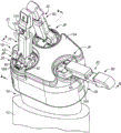
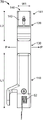
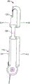
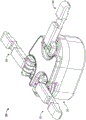
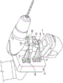
Fig. 1 is a fragmentary perspective view of a robot including a grasper according to an embodiment of the present invention.
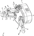
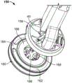
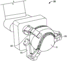
Fig. 2 is a front perspective view of the grasper of fig. 1.
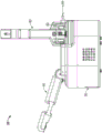
Fig. 3 is a rear perspective view of the grasper of fig. 1.
Fig. 4 is a cross-sectional view of the grasper of fig. 1 taken along line 4-4 of fig. 1.
Fig. 5 is a cross-sectional view of the grasper of fig. 1 taken along line 5-5 of fig. 1.
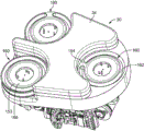
Fig. 6 is a top plan view of the grasper of fig. 1.
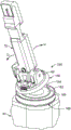
Fig. 7 is a side elevational view of the grasper of fig. 1.
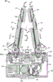
Fig. 8 is a rear elevational view of the grasper of fig. 1.
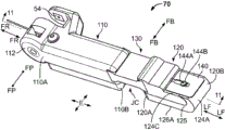
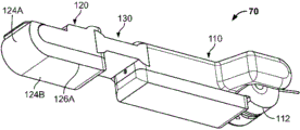
Fig. 9 is a top perspective view of a finger forming part of the grasper of fig. 1.
Fig. 10 is a bottom perspective view of the finger of fig. 9.
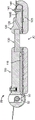
Figure 11 is a cross-sectional view of the finger of figure 9 taken along line 11-11 of figure 9.
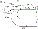
Fig. 12 is an enlarged fragmentary side view of the finger of fig. 9.
Fig. 13 is a top plan view of the finger of fig. 9.
Figure 14 is a side view of the finger of figure 9.
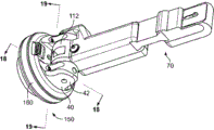
Fig. 15 is a top perspective view of the finger and associated magnetic detaching system of fig. 9.
Fig. 16 is an exploded fragmentary bottom perspective view of the finger and magnetic separation system of fig. 15.
Fig. 17 is an exploded fragmentary top perspective view of the finger and magnetic separation system of fig. 15.
Fig. 18 is a cross-sectional view of the magnetic separation system of fig. 15 taken along line 18-18 of fig. 15.
Fig. 19 is a cross-sectional view of the magnetic separation system of fig. 15 taken along line 19-19 of fig. 15.
Fig. 20 is an exploded fragmentary cross-sectional bottom perspective view of the magnetic separation system of fig. 15.
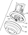
Fig. 21 is a top perspective view of a base forming a portion of the grasper of fig. 1, the base including an abutment forming a portion of the magnetic detachment system.
FIG. 22 is a fragmentary perspective view of the finger and magnetic separation system of FIG. 15 illustrating operation of the magnetic separation system.
Fig. 23-29 illustrate various finger configurations that may be performed by the grasper of fig. 1.
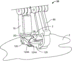
Fig. 30A and 30B illustrate a movement sequence for the grasper of fig. 1 to grasp and pick up an object.
Detailed Description
The present invention now will be described more fully hereinafter with reference to the accompanying drawings, in which exemplary embodiments of the invention are shown. In the drawings, the relative sizes of regions or features may be exaggerated for clarity. This invention may, however, be embodied in many different forms and should not be construed as limited to the embodiments set forth herein; rather, these embodiments are provided so that this disclosure will be thorough and complete, and will fully convey the scope of the invention to those skilled in the art.
It will be understood that when an element is referred to as being "coupled" or "connected" to another element, it can be directly coupled or connected to the other element or intervening elements may also be present. In contrast, when an element is referred to as being "directly coupled" or "directly connected" to another element, there are no intervening elements present. Like numbers refer to like elements throughout.
Additionally, spatially relative terms, such as "below," "lower," "above," "upper," and the like, may be used herein for ease of description to describe one element or feature's relationship to another element(s) or feature(s) as illustrated in the figures. It will be understood that the spatially relative terms are intended to encompass different orientations of the device in use or operation in addition to the orientation depicted in the figures. For example, if the device in the figures is turned over, elements described as "below" or "beneath" other elements or features would then be oriented "above" the other elements or features. Thus, the exemplary term "below" can encompass both an orientation of above and below. The device may be otherwise oriented (rotated 90 degrees or at other orientations) and the spatially relative descriptors used herein interpreted accordingly.
The terminology used herein is for the purpose of describing particular embodiments only and is not intended to be limiting of the invention. As used herein, the singular forms "a", "an" and "the" are intended to include the plural forms as well, unless the context clearly indicates otherwise. It will be further understood that the terms "comprises" and/or "comprising," when used in this specification, specify the presence of stated features, integers, steps, operations, elements, and/or components, but do not preclude the presence or addition of one or more other features, integers, steps, operations, elements, components, and/or groups thereof. As used herein, the expression "and/or" includes any and all combinations of one or more of the associated listed items.
Unless otherwise defined, all terms (including technical and scientific terms) used herein have the same meaning as commonly understood by one of ordinary skill in the art to which this invention belongs. It will be further understood that terms, such as those defined in commonly used dictionaries, should be interpreted as having a meaning that is consistent with their meaning in the context of the relevant art and will not be interpreted in an idealized or overly formal sense unless expressly so defined herein.
Embodiments of the present invention relate to end effectors or graspers. The graspers disclosed herein may form part of a robot or prosthetic device. In particular, the grasper may be mounted on a robotic arm and used to manipulate and grasp objects in a structured or unstructured environment. The grasper may be used as a humanoid robot grasper or "hand" and/or may comply with standards specified under DARPA autonomous robot maneuvering hardware (ARM-H) programs.
Referring to the drawings, a robot 10 (fig. 1) according to an embodiment of the present invention is shown therein and includes an arm 12 and a grasper 20 rotatably coupled to the arm 12 by a wrist joint 14.
The grasper 20 includes a base assembly 30, a first finger 70, a second finger 80, and a thumb 90. The fingers 70, 80 and thumb 90 may be identically constructed, except for their placement on the base 30 and the actuation method and actuation mechanism as discussed below. Unless otherwise specified, "finger" and "fingers" are also referred to as thumbs 90. The grasper 20 has a major or longitudinal axis LG-LG (fig. 4).
The base assembly 30 includes a frame 32 and a palm 34 on a running side of the frame 32. Three magnetic base stages 160 are mounted in the frame 32 and three associated finger base stages 40 are mounted on the three magnetic base stages 160 (fig. 15). During normal operation, each base station 160 and its associated base station 40 are coupled to function effectively as a single unit. The abutments 160 of the fingers 70 and 80 can be rotated at the joint JR.
The fingers 70, 80, 90 may be constructed identically or similarly as discussed above. The exemplary finger 70 will be described, and it will be appreciated that the description will apply equally to the other fingers 80 and 90.
Referring to fig. 9-14, finger 70 includes a proximal phalanx 110 and a distal phalanx 120 coupled by a compliant flexure link 130 at a compliant distal interphalangeal flexure joint JC. The finger 70 also has a hinge feature 112 that couples the finger 70 to its finger base mount 40. The finger 70 has a longitudinal axis LF-LF. More particularly, the proximal phalanx 110 has a proximal end 110A and a distal end 110B. The distal phalanx 120 has a proximal end 120A and a distal end 120B. A hinge feature 112 is provided on the end 110A. The flexure link 130 is fixed to the ends 110B and 120A. The end 120B is free. A distally extending or plate member 140 is mounted on end 120B.
The hinge features 112 are pivotally coupled to the cooperating hinge features 42 (fig. 1) on the finger base station 40 by a pivot pin 50, the pivot pin 50 defining a pin pivot axis FP-FP to form a proximal pin pivot joint JP. The rotational movement of the finger 70 about the pivot joint JP is constrained to pivot about the pivot axis FP-FP in the finger closing pivot direction F and the finger opening pivot direction H. The finger 70 defines a finger lateral plane E that is parallel to each of the longitudinal axis LF-LF and the pivot axis FP-FP. It will be appreciated that the orientation of the pivot axis FP-FP will vary depending on the rotational position of the submount 40 about the axis FR-FR.
In one embodiment, the angular position sensor 54 disposed in the joint JP detects the angular position of the phalanx 110 relative to the base 30. For example, the magnetic encoder may be mounted on one portion of the joint JP (e.g., the hinge feature 43) and the cooperating magnet may be mounted on another portion of the joint JP (e.g., the hinge feature 112).
A biasing member 52 is provided in the joint JP (fig. 4 and 7). According to some embodiments, the biasing member 52 is a torsion spring, and in particular, may be a helical torsion spring. The torsion spring 52 acts as a balance spring or biasing return spring. Without the restraint of the chordae or external forces, the torsion spring 52 will force the finger 70 to pivot in direction I to the large open position.
The flexure link 130 is semi-rigid, flexible, resilient, and compliant. In some embodiments, the flexure link 130 is formed of an elastomeric material. The flexure link 130 preferentially flexes or bends in each of the inward, primary and outward directions M, N about the distal or flexure joint pivot axis FB-FB. The flexure link 130 may also flex or bend in opposite lateral or side, minor directions P perpendicular or transverse to the finger closing direction F. Thus, the flexure link 130 and the joint JC have a first compliance in the first direction M and a second compliance in the second direction P. The second direction P is perpendicular or transverse to the cord retraction direction H. The first compliance is greater than the second compliance (i.e., less force is required to deflect the flexure link 130 in the first direction). When relaxed and unloaded, the flexure link 130 will resiliently return to the relaxed position or state, as shown in fig. 9-11. According to some embodiments, the proximal phalanx 110 and the distal phalanx 120 are substantially parallel or coaxial when the flexure link 130 is in its return position.
The tendon cable 60A is routed from the actuator 60 through the tendon races 158, 168 in the abutments 40, 160, along the inner side of the hinge feature 112, through the tendon race 118 in the proximal phalanx 110, across the flex joint JR, and through the race 128 in the distal phalanx 120, and anchored to the distal phalanx 120 (e.g., in the race 28). The actuator 60 may pull the chordae 60A through the raceways 118, 158, 168 in the direction H to pivot the finger 70 in the closing direction F. The actuator 60 may then release or loosen the chordae 60A in the opposite direction to allow the finger 70 to pivot in the opening direction I under the torque of the torsion spring 52.
The operation of the finger 70 (and the corresponding operation of the finger 80 and thumb 90) will now be discussed in more detail. With the finger 70 in the fully open position (fig. 23), the actuator 60 pulls the chordae tendineae 60A. The spring force or resistance from the torsion spring 52 is less than the stiffness or spring force or bending resistance of the flexure link 130. Thus, assuming that the proximal phalanx 110 does not encounter external resistance, when the chordae tendineae 60A apply a tensile load to the finger 70, the finger 70 will be displaced firstly about the pin pivot JP and secondly about the flex joint JC. That is, the angular distance that the proximal phalanx 110 pivotally rotates about the pivot pin axis FP-FP will be greater than the angular distance that the distal phalanx 120 pivotally rotates or bends about the flex joint axis FB-FB.
If and when the proximal phalanx 110 is obstructed or reaches a limit (e.g., falls onto the base 30) by an external object (e.g., a gripped object), a greater portion or all of the tensile load of the chordae tendineae 60A will be applied to the flex joint JC, and then the distal phalanx 120 will bend or rotate about the flex joint axis FB-FB at a greater rate than the rate at which the proximal phalanx 110 rotates about the pin pivot axis FP-FP.
The difference in the rates at which the phalanges 110 and 120 are displaced about their respective pivot axes will depend on the relative effective spring forces of the torsion spring 52 and the flexure link 130. According to some embodiments, the spring force of the flex joint JC is at least 8 times, and in some embodiments, ranges from about 8 to 12 times, the spring force of the pin pivot joint JP. In some embodiments, the spring rate of the torsion spring 52 is large enough to completely counteract the force of gravity of the finger 70 in any desired orientation when the grasper 20 is at rest and not acted upon by a foreign object. According to some embodiments, the spring force of the torsion spring 52 is between about 100% and 150% of the minimum force necessary to completely counteract the force of gravity of the finger 70 in any desired orientation when the grasper 20 is at rest and not acted upon by an external object. By minimizing the torsional spring force, designers can reduce the required spring rate of the flex joint JC. Further, the return force that the actuator 60 must overcome is reduced.
Notably, the spring force of the flex joint JC can be as high as desired and/or needed. In particular, as the size of the grasper is scaled up and used to lift larger and heavier objects, the spring force of the flex joint JC may be increased.
Figures 1 and 23-29 show various configurations of fingers 70, 80, 90 that may be assumed or implemented by the grasper 20.
Fig. 23 shows the wide open or ready position in which the chordae 60A, 62A, 64A are slack, allowing the torsion spring 52 to force the respective finger 70, 80, 90 to its limit in its opening direction.
Fig. 1 shows the fingers 70, 80 in a retracted configuration, which may be achieved when the actuators 60, 62 pull the fingers 70, 80 (via chordae tendineae 60A, 62A) closed without significant resistance. For this operation, the finger rotation actuator 68 may first be used to rotate the fingers 70, 80 relative to each other about their substantially parallel pivot axes FP-FP. Fig. 24 shows a modified retracted configuration for holding and/or manipulating an object 2, such as a flat key.
Fig. 23, 25 and 26 show the fingers 70, 80, 90 progressing from a wide open configuration (fig. 23) into a power gripping configuration (fig. 26) wherein the thumb 90 is intersected by the fingers 70, 80. For this operation, the rotary actuator 68 may be used to rotate the fingers 70, 80 relative to the thumb 90 about the pivot axes FP-FP of the substantially parallel fingers 70, 80, 90, as shown in fig. 25. Fig. 27 shows a modified power gripping configuration for holding and/or manipulating an object 4, such as a power tool. The exemplary power tool 4 has a handle 4A and a trigger 4B. The grasper 20 securely holds the handle 4A using the fingers 70, 80, 90 and may also be used to operate the trigger 4B by applying tension to the fingers 80 via the chordae tendineae 62A and releasing tension from the fingers 80 so that their distal phalanges 120 will bend independently at the flex joint JC and depress and release the trigger 4B (the proximal phalanges 110 are restrained or constrained by the handle 4A).
Fig. 28 shows the fingers 70, 80, 90 in a ball grip position. For this operation, the fingers 70, 80 rotate so that their pivot axes FP-FP extend at an oblique angle relative to the pivot axis FP-FP of the thumb 90. Fig. 29 shows a modified ball gripping position in which the grasper 20 holds an object 6, such as a ball.
It will be appreciated that the foregoing is not an exhaustive list of configurations and manipulations that can be achieved using grasper 20.
The relationship between the length of the phalanges 110 and 120 and the position of the base of the fingers and thumb can provide advantageous performance. In some embodiments, these relationships are scalable.
According to some embodiments, the length L1 (fig. 13) of the proximal phalanx 110 of each finger 70, 80 is greater than the length L2 of the distal phalanx 120 of the same finger. According to some embodiments, the length L1 ranges from about 0.60 to 0.66 times the length L2.
In some embodiments, the average distance D1 (fig. 6) from the base pivot joint JP of each finger 70, 80 to the thumb 90 pivot joint JP ranges from about 1.30 to 1.44 times the average proximal phalanx length L1.
According to some embodiments, the major dimension L3 (fig. 6) of the palm 34 ranges from about 1.21 to 1.33 times the average proximal phalanx length L1.
In some embodiments, the spacing D2 (fig. 6) between the pivot joints JP of the fingers 70, 80 ranges from about 0.97 to 1.08 times the average proximal phalanx length L1.
Providing a finger having both a proximal pin pivot joint and a distal flex joint as described may provide certain advantages. Rigid pivoting at the base of the fingers provides both contractive stability and torsional strength to facilitate fine manipulation and weight lifting. Flex joints at the distal joints provide robustness against misuse and improve the ability of the finger to conform or conform to an object of unknown shape. According to some embodiments and as shown, the pin pivot axis FP-FP of each finger is substantially parallel to the finger's primary deflection axis FB-FB.
Referring to fig. 9-12, according to some embodiments, the grasper 20 is provided with a nail system 141. The nail system 141 includes a distal plate member 140, the distal plate member 140 being mounted on the distal phalanx 120 of each finger 70, 80, 90 near its distal end face 12. Only one of the fingers 70 will be described hereinafter. However, it will be appreciated that the description applies equally to the fingers 80 and 90.
The distal plate member 140 includes a base portion 144 and a free terminal lifting edge 142A. The base portion 144 has a slot 144A and is adjustably secured to the dorsal surface 124C of the phalanx 120 by a fastener 144B, such as a screw. The free edge 142A is located adjacent the end face 124A. In some cases, and as shown, the distal plate member 140 has an extension 142, the extension 142 terminating in a free edge 142A and depending (hanging) or extending axially beyond a location 147 where the plate member 140 diverges from the phalanges 120 to form a flange. However, in other embodiments, free edge 142A may coincide with or be inboard of location 147.
In some embodiments, the fastener 144B and the groove 144A may serve as an adjustment mechanism. More particularly, the fasteners 144B may be loosened, the plate member 140 slid to position the edge 142A relative to the end face 124A as desired, and then the fasteners 144B re-tightened to secure the plate member 140 in place. It will be appreciated that other suitable adjustment mechanisms may be used.
The plate member 142 is relatively thin, at least in the region of the free edge 142A. According to some embodiments, free edge 142A has a thickness T1 (fig. 12) in a range of approximately 0.02 inches to 0.03 inches. In some embodiments, the length L4 of extension 142 from location 147 to free edge 142A is at least 1mm, and in some embodiments, from about 1.5 mm to 2.5 mm. According to some embodiments, the free edge 142A is substantially parallel to the flex joint axis FB-FB.
According to some embodiments and as shown, the end face 124A and the plate member 140 are oppositely configured and arranged to define a laterally extending notch, groove, or undercut 146 between an underside of the extension section 142 and an opposing surface of the end face 124A. In some embodiments and as shown, the end face 124A is shaped to taper axially to form an undercut 146. In some embodiments, the end face 124A is circular or curvilinear, and in some embodiments, its cross-section is arcuate (i.e., in a plane perpendicular to the plane E and parallel to the longitudinal axis of the distal phalanx 120).
According to some embodiments, the depth D3 of the undercut 146 ranges from about 1mm to 3 mm. According to some embodiments, the width W1 of the undercut 146 ranges from about 10 mm to 25 mm.
In some embodiments, the plate member 140 is rigid (e.g., formed of steel or stainless steel) and the end face 124A is relatively soft or compliant (e.g., formed of pliable rubber). As shown, the distal phalanx 120 includes a cushion 125, and the cushion 125 includes an end surface 124A. In some embodiments, the pad 125 has a hardness ranging from about 0 shore a to 60 shore a, and in some embodiments, about 10 shore a to 40 shore a, and the plate member 140 has a stiffness of at least about 100 Gpa, and in some embodiments, at least 180 Gpa.
The plate member 140 may be used to pick up, engage and/or manipulate objects in a manner that is not feasible or would be cumbersome without the "fingernail". The combination of the thin rigid plate member 140 ("fingernail") and the flexible soft pad 125 ("finger tip") enables a finger to capture an edge of an object therebetween (i.e., in the undercut 146). For example, if the object is disposed on a support surface (e.g., a table surface), the plate member 140 may be pressed against the support surface, then translated beneath the object (between the object and the support surface), and then used to lift the object. The compliant flex joint JC supplements the functionality of the nail system 141. The joint compliance enables the plate member 140 to be adaptively aligned and maintained in contact with the support surface.
Referring to fig. 30A and 30B, therein is shown the grasper 20 performing a series of steps or movements to grasp and pick up an object 2 (as shown, a relatively flat key) from a flat surface Z (e.g., a table or floor).
Initially, the key 2 lies flat on the surface Z. Referring to fig. 30A, the grasper 20 is positioned such that the extension section 142 of the plate member 140 of the finger 70 is placed on the surface Z adjacent to the side edge 2A of the key 2, with the undercut 146 and the cushion 125 overlying the extension section 142. The phalanges 120 of the finger 80 are placed against the surface Z and driven in the direction J towards the key 2 and the finger 70, the fingers 70 and 80 being oppositely disposed in a retracted configuration. As finger 80 is actuated in direction J, it engages side edge 2B of key 2 and pushes side edge 2A onto plate member 140 (in some embodiments, into undercut 146 and between extension section 142 and cushion 125). The phalanges 120 of the finger 80 are driven further towards the finger 70 and upwards to lift the side edge 2B from the surface Z. The key 2 thus flips, or pivots upwards about its edge 2A and in direction K towards the end face 124A of the finger 70, as shown in fig. 30A, the edge 2A being trapped between the plate member 140 and the pad 125. Referring to fig. 30B, the finger 80 is used to continue lifting the key 2 and converging with the finger 70 until the key 2 is sandwiched between the end faces 124A of the fingers 70 and 80, the end faces 124A engaging the opposing faces 2D and 2C, respectively, of the key 2.
The "fingernail" or "nails" of the grasper 20 and the cooperative movement of the fingers 70, 80 (and in some embodiments, the base 30 and/or the arm 12) may thus be used to grasp, remove and manipulate relatively flat objects, such as keys (or credit cards, etc.), from a flat surface.
In some embodiments and as shown, the axially extending leading edge 126A of the distal phalanx 120 is sharp or distinct, while the front face 124B (i.e., the contact or engagement face) is substantially flat or planar (fig. 9 and 10). According to some embodiments, the side walls of the distal phalanx 120 that form the side edges 126A with the front face 124B are substantially flat at and near the front face 124B, and in some embodiments, extend substantially perpendicular to the plane of the front face 124B. The front surface 124B may be textured. As shown, these edges 126A and front 124B may be edges and front of the cushion 125. In some embodiments, the plane of the front face 124B is substantially parallel to the pivot pin axis FP-FP and the flex joint primary axis FB-FB.
In use, the depicted configuration assists in stabilizing the distal phalanx 120. For example, when the fingers 70, 80 are used to pinch an object between the distal phalanges 120, the sharp side edges 126A and the flat front face 124B may reduce or eliminate the tendency of the distal phalanges 120 to twist about their flex joint JC. The sharp edge 124A may also assist in making a secure and precise engagement with an object.
In some embodiments, the distal phalanx 120 is prismatic in shape and has a substantially rectangular cross-section. In some embodiments, the proximal phalanx 110 is also prismatic in shape and has a substantially rectangular cross-section.
Referring to fig. 15-22, the grasper 20 may also be provided with a magnetic detachment system or mechanism 150 that couples each of the fingers 70, 80, 90 to the base 30. The separation characteristics of each of the fingers 70, 80, 90 may be substantially the same or similar, and thus the following description of the finger 70 applies equally to the fingers 80 and 90.
The magnetic separation system 150 includes a finger base station 40 and a magnetic base station 160. A magnet 166 is fixed in the submount 160 and a ferromagnetic component or plate 156 (e.g., formed of steel) is affixed in the submount 40. A magnetic field concentrator 153 may be provided in the submount 160.
The abutment 40 has a circumferentially extending locator flange 152, the locator flange 152 defining a rotational alignment notch 154 therein. The abutment 160 has a circumferentially extending semi-annular locator groove 162, the locator groove 162 having a rotational alignment tab 164 therein. The locator flange 152 is seated in the locator groove 162 such that the tab 164 is seated in the slot 154. The chordae 60A extend through axial chordae raceways 158 and 168 defined in abutments 40 and 160, respectively. Also, in the case of finger 80, chordae 62A extend through raceways 158 and 168. In the case of the thumb 90, the chordae tendineae 64A and 66A extend through respective ones of the axially extending raceways 158 and 168.
In use, the magnetic separation system 150 may be used to disengage the fingers 70, 80, 90 from the base 30 to prevent or reduce the risk of injury to the fingers or joints. When the load on the finger exceeds a prescribed threshold load, the magnetic attraction between the members 156 and 166 is overcome and the submount 40 is separated (partially or fully) from the submount 160. For example, the finger 70 and its submount 40 may be deflected away from the cooperating submount 160 in a deflection direction G, as shown in fig. 22. When the load on the finger is relieved (e.g., by removing an object or operating an associated actuator to loosen the chordae tendineae), the magnetic attraction or tension in the chordae tendineae will again pull the abutments 40 and 160 together. For example, the finger 70 and its abutment 40 may be returned or pivoted back onto the cooperating abutment 160 in the return direction H, as shown in fig. 22. The pulling force of the tendon through the raceways 158, 168 will tend to pull the abutments 40, 160 into coaxial alignment. With a small amount of separate deflection of the abutment 40 from the abutment 160, the shape of the locator features 152, 154, 162, 164 can automatically guide the abutments 40 and 160 back into rotational alignment, whereupon the abutments 40 and 160 will again interlock. Applying additional tension to the chordae also rotates the abutments 40 and 160 into rotational alignment. In some cases, abutments 40 and 160 can be rotationally aligned by rotating abutment 160 using actuator 68. The abutments 160 will be slidably rotated relative to the corresponding abutments 40 until their locator features are aligned, whereupon the abutments 40 and 160 will nest and interlock. In some cases, it may be necessary to manually realign and reseat the abutments 40 and 160.
In some embodiments, the magnetic breakaway system 150 does not compromise the ability of the grasper 20 to lift heavy objects. Because the tendon or cable extends axially through both abutments 40, 160 and is substantially perpendicular to the face of the magnet 166, the tendon pulls the abutments 40, 160 together. Typically, the abutments 40 and 160 will only be removed by a twisting force on the finger.
As mentioned above and as shown in fig. 5, the thumb 90 is provided with two separate chordae tendineae 64A and 66A that are connected to respective actuators 64 and 66. Chordae 64A may be considered to be contracting tendons, while chordae 66A may be considered to be antagonistic.
The chordae tendineae 64A are routed in the same manner as described above and anchored to the distal phalanx 120 of the thumb 90. Chordae 66A are routed through the outer races 158, 168, over the hinge feature 42, and anchored to the posterior side of the proximal phalanx 110 by screw 43.
The chordae 64 and 66A may be used together to control movement of the distal phalanx 120 of the thumb 90 independently of the proximal phalanx 110 thereof, except that they can function in the same manner as described above with respect to the fingers 70, 80 using the chordae 64A. More particularly, the chordae 66A may be used to hold the proximal phalanx 110 in place, effectively stopping the proximal phalanx 110 from further rotation in the closing direction F while the actuator 64 pulls on the chordae 64A. Since the proximal phalanx 110 is held in place, the distal phalanx 120 independently bends in direction M at the flex joint JC without simultaneously pivoting the proximal phalanx 110 in the closing direction F. The chordae 66A may extend to allow the distal phalanx 120 to resiliently bend back in direction N about the flex joint JC.
According to some embodiments, the chordae 60A, 62A, 64A, 66A are capable of transmitting a sustained tensile load in the range of about 60 lbf to 120 lbf, exhibit low energy storage after bending, and are robust to bending radii of less than one millimeter.
The foregoing is illustrative of the present invention and is not to be construed as limiting thereof. Although a few exemplary embodiments of this invention have been described, those skilled in the art will readily appreciate that many modifications are possible in the exemplary embodiments without materially departing from the novel teachings and advantages of this invention. Accordingly, all such modifications are intended to be included within the scope of this invention. Therefore, it is to be understood that the foregoing is illustrative of the present invention and is not to be construed as limited to the specific embodiments disclosed, and that modifications to the disclosed embodiments, as well as other embodiments, are intended to be included within the scope of the invention.
Claims (24)
1. A compliant underactuated grasper comprising:
a base;
two digit and the thumb toe opposite to the two digit, wherein the digit and the thumb toe each include:
a proximal phalanx;
a distal phalanx;
a distal joint directly connecting the proximal phalanx to the distal phalanx, the distal joint being compliant in a first direction;
a proximal joint directly connecting the proximal phalanx to the base, the proximal joint being compliant in a second direction; and
a tendon for moving the proximal and distal phalanges, wherein the tendon is substantially parallel to the first direction of compliance and substantially changes the compliance of the distal joint in the first direction; and
at least one actuator to move the digit and the thumb;
wherein each distal phalanx has a length that is 0.60 to 0.66 times the length of the proximal phalanx connected thereto;
wherein the average distance from the proximal joint of each of the two digits to the thumb is 1.30 to 1.44 times the average length of the proximal phalanges of the two digits; and
wherein the grasper has less than a degree of freedom of the actuator.
2. The grasper of claim 1 wherein:
the base comprises a palm between the digit and the thumb; and is
The palm has a major dimension in a range of 1.21 to 1.33 times the average length of the proximal phalanx.
3. The grasper of claim 1 wherein a spacing between the proximal joints of the digit ranges from 0.97 to 1.08 times the average length of the proximal phalanx.
4. A compliant underactuated grasper comprising:
a palm base;
a first and a second finger, wherein each of the first and second fingers comprises:
a proximal phalanx;
a distal phalanx;
a compliant flex joint connecting the distal phalanx to the proximal phalanx; and
a pin joint connecting the proximal phalanx to the palm base, the pin joint constraining angular movement of the proximal phalanx relative to the palm base to rotate about a pin pivot axis; and
at least one actuator to move the first and second fingers;
wherein the grasper has an actuator with less than a degree of freedom and includes first and second revolute joints connecting the first and second fingers, respectively, to the palm base such that the first and second fingers are rotatable relative to the palm base, wherein the first and second fingers are rotatable relative to the palm base about the first and second revolute joints to reorient their pin pivot axes relative to the palm base and to change an angle defined between the pin pivot axes of the first finger and the second finger.
5. The grasper of claim 4 including a pin joint angle sensor associated with each of the first and second fingers.
6. The grasper of claim 4 further comprising:
a thumb, comprising:
a proximal phalanx;
a distal phalanx;
a compliant flex joint connecting the distal phalanx to the proximal phalanx; and
a pin joint connecting the proximal phalanx to the palm base, the pin joint constraining angular movement of the proximal phalanx relative to the palm base to rotate about a pin pivot axis; and
at least one actuator to move the thumb independently of the first and second fingers.
7. The grasper of claim 4 wherein:
the first swivel joint enables the first finger to rotate about a first axis of rotation;
the second rotational joint enables the second finger to rotate about a second axis of rotation; and is
The first and second axes of rotation are substantially parallel.
8. The grasper of claim 4 including at least one finger rotation actuator operable to forcibly rotate the first and second fingers about the first and second rotary joints.
9. The grasper of claim 4 wherein the first and second fingers are linked such that the first and second fingers rotate in tandem about the first and second rotary joints in opposite rotational directions to one another.
10. The grasper of claim 4 further comprising:
a thumb, comprising:
a proximal phalanx;
a distal phalanx;
a compliant flex joint connecting the distal phalanx to the proximal phalanx; and
a joint connecting the proximal phalanx to the base of the palm; and
at least one actuator to move the thumb independently of the first and second fingers.
11. The grasper of claim 4 wherein, with respect to each of the first and second fingers:
the proximal phalanx is connected to the palm base for rotation about the pivot axis in a first direction and a second direction;
the grasper includes a return biasing spring to drive the proximal phalanx in the second direction to a return position;
the return biasing spring has a first spring rate;
the flex link is configured to bias the distal phalanx to an open position relative to the proximal phalanx and has a second spring rate; and is
The second spring rate is greater than the first spring rate.
12. The grasper of claim 11 wherein:
further comprising a chordae tendineae for moving the proximal and distal phalanges;
the first spring rate is sufficient to hold the proximal phalanx in the returned position in any orientation of the grasper with the chordae tendineae slack; and is
The second spring rate is sufficient to hold the distal phalanx in the open position in any orientation of the grasper with the chordae tendineae slack.
13. A compliant underactuated grasper comprising:
a palm base;
a first and a second finger, wherein each of the first and second fingers comprises:
a proximal phalanx;
a distal phalanx;
a compliant flex joint connecting the distal phalanx to the proximal phalanx;
a pin joint connecting the proximal phalanx to the palm base for rotation about a pin pivot axis in a first direction and a second direction; and
a tendon cable for moving the proximal and distal phalanges such that movement of the tendon cable generates angular motion of the proximal phalanx about the pin pivot axis at a rate greater than angular motion of the distal phalanx about the flex joint; and
at least one actuator to move the first and second fingers;
wherein the grasper has less than a degree of freedom of the actuator.
14. The grasper of claim 13 wherein the flex joint includes a flex link formed of a compliant elastomeric material.
15. The grasper of claim 13 wherein, with respect to each of the first and second fingers:
the grasper includes a return biasing spring to drive the proximal phalanx in the second direction to a return position;
the return biasing spring has a first spring rate;
the flex link is configured to bias the distal phalanx to an open position relative to the proximal phalanx and has a second spring rate; and is
The second spring rate is greater than the first spring rate.
16. The grasper of claim 15 wherein the second spring rate is at least eight times greater than the first spring rate.
17. The grasper of claim 15 wherein:
the first spring rate is sufficient to hold the proximal phalanx in the returned position in any orientation of the grasper with the chordae tendineae slack; and is
The second spring rate is sufficient to hold the distal phalanx in the open position in any orientation of the grasper with the chordae tendineae slack.
18. A compliant underactuated grasper comprising:
a palm base;
a first and a second finger, wherein each of the first and second fingers comprises:
a proximal phalanx;
a distal phalanx;
a compliant flex joint connecting the distal phalanx to the proximal phalanx;
a pivot joint connecting the proximal phalanx to the palm base for rotation about the pivot joint in a first direction and a second direction;
a chordae tendineae for moving the proximal phalanx in the first direction; and
a return biasing spring to drive the proximal phalanx in the second direction to a return position, wherein a first spring rate of the return biasing spring is sufficient to hold the proximal phalanx in the return position in any orientation of the grasper with the tendon cable slack; and
at least one actuator associated with each chordae tendineae;
wherein the grasper has less than a degree of freedom of the actuator,
wherein the flex joint is configured to bias the distal phalanx into an open position relative to the proximal phalanx and has a second spring rate that is greater than the first spring rate.
19. The grasper of claim 18 wherein the return biasing spring comprises a torsion spring.
20. The grasper of claim 18 wherein the second spring rate is at least eight times greater than the first spring rate.
21. A compliant underactuated grasper comprising:
a base;
two digit and the thumb toe opposite to the two digit, wherein the digit and the thumb toe each include:
a proximal phalanx;
a distal phalanx;
a distal joint directly connecting the proximal phalanx to the distal phalanx, the distal joint being compliant in a first direction;
a proximal joint directly connecting the proximal phalanx to the base, the proximal joint being compliant in a second direction; and
a tendon for moving the proximal and distal phalanges, wherein the tendon is substantially parallel to the first direction of compliance and substantially changes the compliance of the distal joint in the first direction; and
at least one actuator to move the digit and thumb;
wherein the thumb toe further comprises a second tendon cable for selectively inhibiting the proximal phalanx thereof opposite the tendon cable to enable the distal phalanx to move independently of the proximal phalanx; and is
Wherein the grasper has less than a degree of freedom of the actuator.
22. The grasper of claim 21 including a first actuator to actuate the tendon of the thumb toe and a second actuator to actuate the second tendon of the thumb toe.
23. The grasper of claim 21 wherein each digit does not include a tendon for selectively inhibiting the proximal phalanx thereof opposite the tendon cable to enable the distal phalanx to move independently of the proximal phalanx.
24. The grasper of claim 21 wherein each of the tendons is capable of transmitting a continuous tensile load in a range of 60 lbf to 120 lbf, exhibits low energy storage after bending, and is robust to bending radii of less than one millimeter.
Applications Claiming Priority (13)
| Application Number | Priority Date | Filing Date | Title |
|---|---|---|---|
| US201261724512P | 2012-11-09 | 2012-11-09 | |
| US201261724506P | 2012-11-09 | 2012-11-09 | |
| US201261724517P | 2012-11-09 | 2012-11-09 | |
| US61/724506 | 2012-11-09 | ||
| US61/724512 | 2012-11-09 | ||
| US61/724517 | 2012-11-09 | ||
| US13/833,580 US9004559B2 (en) | 2012-11-09 | 2013-03-15 | Compliant underactuated grasper |
| US13/833631 | 2013-03-15 | ||
| US13/833687 | 2013-03-15 | ||
| US13/833580 | 2013-03-15 | ||
| US13/833,687 US9089977B2 (en) | 2012-11-09 | 2013-03-15 | Compliant underactuated grasper |
| US13/833,631 US8991885B2 (en) | 2012-11-09 | 2013-03-15 | Compliant underactuated grasper |
| CN201380058552.1A CN104936749B (en) | 2012-11-09 | 2013-11-08 | Compliance owes to actuate grasper |
Related Parent Applications (1)
| Application Number | Title | Priority Date | Filing Date |
|---|---|---|---|
| CN201380058552.1A Division CN104936749B (en) | 2012-11-09 | 2013-11-08 | Compliance owes to actuate grasper |
Publications (2)
| Publication Number | Publication Date |
|---|---|
| CN107756425A CN107756425A (en) | 2018-03-06 |
| CN107756425B true CN107756425B (en) | 2021-08-31 |
Family
ID=50685183
Family Applications (2)
| Application Number | Title | Priority Date | Filing Date |
|---|---|---|---|
| CN201380058552.1A Active CN104936749B (en) | 2012-11-09 | 2013-11-08 | Compliance owes to actuate grasper |
| CN201710983311.8A Active CN107756425B (en) | 2012-11-09 | 2013-11-08 | Compliant underactuated grasper |
Family Applications Before (1)
| Application Number | Title | Priority Date | Filing Date |
|---|---|---|---|
| CN201380058552.1A Active CN104936749B (en) | 2012-11-09 | 2013-11-08 | Compliance owes to actuate grasper |
Country Status (4)
| Country | Link |
|---|---|
| EP (1) | EP2917002B1 (en) |
| JP (2) | JP6484557B2 (en) |
| CN (2) | CN104936749B (en) |
| WO (1) | WO2014074840A1 (en) |
Families Citing this family (15)
| Publication number | Priority date | Publication date | Assignee | Title |
|---|---|---|---|---|
| FR3016543A1 (en) * | 2014-01-22 | 2015-07-24 | Aldebaran Robotics | HAND INTENDED TO EQUIP A HUMANIDE ROBOT WITH IMPROVED FINGERS |
| CA2987480C (en) | 2015-06-11 | 2024-01-16 | Soft Robotics, Inc. | Modular robotic systems |
| JP7155479B2 (en) | 2017-05-15 | 2022-10-19 | Thk株式会社 | Hand Mechanism, Grasping System, and Grasping Program |
| JP7116052B2 (en) | 2017-05-15 | 2022-08-09 | Thk株式会社 | grasping system |
| WO2019031502A1 (en) | 2017-08-10 | 2019-02-14 | Thk株式会社 | Hand mechanism and gripping system |
| JP7069512B2 (en) * | 2017-11-15 | 2022-05-18 | Thk株式会社 | Gripping system and its control method |
| JPWO2019102913A1 (en) * | 2017-11-22 | 2020-11-19 | Thk株式会社 | Gripping system |
| JP6680757B2 (en) | 2017-12-28 | 2020-04-15 | ファナック株式会社 | Gripping hand |
| KR102259379B1 (en) * | 2018-01-24 | 2021-06-01 | 주식회사 엘지에너지솔루션 | Electrode transferring appratus of battery cell |
| CN108673542B (en) * | 2018-05-04 | 2021-04-27 | 江南大学 | Electric-gas composite driving series flexible hinge framework flexible manipulator |
| US11537219B2 (en) | 2018-08-07 | 2022-12-27 | The Research Foundation For The State University Of New York | Feedback input apparatus and method for use thereof |
| JP6829738B2 (en) | 2019-03-15 | 2021-02-10 | Thk株式会社 | Gripping system and gripping method |
| DE202020001067U1 (en) * | 2020-03-18 | 2020-07-15 | ACCREA Engineering | Gripping element and robot arm or support aid or assistance system |
| DE102020207035A1 (en) * | 2020-06-04 | 2021-12-09 | Kuka Deutschland Gmbh | Gripper fingers and grippers with such gripper fingers |
| TWI736467B (en) | 2020-11-11 | 2021-08-11 | 財團法人工業技術研究院 | Robotic palm and finger device thereof |
Family Cites Families (22)
| Publication number | Priority date | Publication date | Assignee | Title |
|---|---|---|---|---|
| JPS5525986Y2 (en) * | 1977-05-25 | 1980-06-23 | ||
| JPS5834787A (en) * | 1981-08-25 | 1983-03-01 | 富士通フアナツク株式会社 | Hand for industrial robot |
| JP2001277174A (en) * | 2000-03-30 | 2001-10-09 | Miyazaki Prefecture | Finger joint mechanism and gripping unit using it |
| JP2004174625A (en) * | 2002-11-25 | 2004-06-24 | Sony Corp | Hand structure of robot device, robot device, driving device and driving method |
| JP4313125B2 (en) * | 2003-09-12 | 2009-08-12 | 本田技研工業株式会社 | Robot hand |
| GB0409548D0 (en) * | 2004-04-29 | 2004-06-02 | King S College London | Robotic hand |
| CN1330465C (en) * | 2004-10-23 | 2007-08-08 | 江南大学 | Plate spring skeleton hydrulic pneumatic flexible bending joint |
| JP2006159320A (en) * | 2004-12-03 | 2006-06-22 | Sharp Corp | Robot hand |
| JP4355781B2 (en) * | 2006-07-12 | 2009-11-04 | 国立大学法人東京工業大学 | Gripping device |
| WO2008058061A2 (en) * | 2006-11-03 | 2008-05-15 | President And Fellows Of Harvard College | Robust compliant adaptive grasper and method of manufacturing same |
| JP4983245B2 (en) * | 2006-12-21 | 2012-07-25 | 株式会社安川電機 | Robot and control method |
| JP4965413B2 (en) * | 2007-11-26 | 2012-07-04 | トヨタ自動車株式会社 | Robot hand |
| CN101244563A (en) * | 2008-02-23 | 2008-08-20 | 中国科学院合肥物质科学研究院 | Manipulator for imitating human hand household service |
| US8534983B2 (en) * | 2008-03-17 | 2013-09-17 | Irobot Corporation | Door breaching robotic manipulator |
| JP5024227B2 (en) * | 2008-08-07 | 2012-09-12 | トヨタ自動車株式会社 | Robot hand |
| CN101412220B (en) * | 2008-11-28 | 2011-01-19 | 北京邮电大学 | Telescopic manipulator |
| CN101844358B (en) * | 2009-03-24 | 2011-07-27 | 中国科学院合肥物质科学研究院 | Finger rotating and moving device of configuration-changeable robotic gripper and working method thereof |
| KR20110005146A (en) * | 2009-07-09 | 2011-01-17 | 한양대학교 산학협력단 | Robot hand |
| CN201519961U (en) * | 2009-09-09 | 2010-07-07 | 北京航空航天大学 | Multi-joint linkage multiple-finger skillful hand |
| WO2011118646A1 (en) * | 2010-03-24 | 2011-09-29 | 株式会社安川電機 | Robot hand and robot device |
| WO2012129254A2 (en) * | 2011-03-21 | 2012-09-27 | Sri International | Mobile robotic manipulator system |
| CN102357884A (en) * | 2011-10-14 | 2012-02-22 | 清华大学 | Quickly-grabbed under-actuated robot hand device |
-
2013
- 2013-11-08 EP EP13854112.3A patent/EP2917002B1/en active Active
- 2013-11-08 CN CN201380058552.1A patent/CN104936749B/en active Active
- 2013-11-08 CN CN201710983311.8A patent/CN107756425B/en active Active
- 2013-11-08 WO PCT/US2013/069182 patent/WO2014074840A1/en active Application Filing
- 2013-11-08 JP JP2015541930A patent/JP6484557B2/en not_active Expired - Fee Related
-
2019
- 2019-02-15 JP JP2019025484A patent/JP6811267B2/en active Active
Also Published As
| Publication number | Publication date |
|---|---|
| EP2917002B1 (en) | 2017-09-27 |
| WO2014074840A1 (en) | 2014-05-15 |
| JP2015533669A (en) | 2015-11-26 |
| JP2019107769A (en) | 2019-07-04 |
| JP6811267B2 (en) | 2021-01-13 |
| EP2917002A4 (en) | 2016-09-21 |
| EP2917002A1 (en) | 2015-09-16 |
| CN104936749B (en) | 2017-11-17 |
| CN104936749A (en) | 2015-09-23 |
| JP6484557B2 (en) | 2019-03-13 |
| CN107756425A (en) | 2018-03-06 |
Similar Documents
| Publication | Publication Date | Title |
|---|---|---|
| CN107756425B (en) | Compliant underactuated grasper | |
| US9327412B2 (en) | Compliant underactuated grasper | |
| US9089977B2 (en) | Compliant underactuated grasper | |
| US8991885B2 (en) | Compliant underactuated grasper | |
| EP3265274B1 (en) | Compliant adaptive robot grasper | |
| Backus et al. | An adaptive three-fingered prismatic gripper with passive rotational joints | |
| JP2015533669A5 (en) | ||
| Odhner et al. | Precision grasping and manipulation of small objects from flat surfaces using underactuated fingers | |
| US11679511B2 (en) | Robotic end effector with dorsally supported actuation mechanism | |
| US9814604B2 (en) | Gripping device | |
| US20090025502A1 (en) | Manipulator and robot | |
| US20110068595A1 (en) | Robotic finger assembly | |
| US10709584B2 (en) | Adaptive robotic finger prosthesis for grasping arbitrary object shape | |
| JPH04501682A (en) | clutch mechanism | |
| JP2006000992A (en) | Robot hand | |
| Gao et al. | Mechanically programmable jamming based on articulated mesh structures for variable stiffness robots | |
| JP7341505B2 (en) | robot hand | |
| US20210197399A1 (en) | Compliant Gripper | |
| JP2023108531A (en) | end effector | |
| JP2012066351A (en) | Hand unit for robot and robot | |
| O’Brien et al. | On the Development of a Low-Cost, Lightweight, Under-Actuated Prosthetic Gripper |
Legal Events
| Date | Code | Title | Description |
|---|---|---|---|
| PB01 | Publication | ||
| PB01 | Publication | ||
| SE01 | Entry into force of request for substantive examination | ||
| SE01 | Entry into force of request for substantive examination | ||
| GR01 | Patent grant | ||
| GR01 | Patent grant |