CN107750372B - Method and device for three-dimensional reconstruction of scene and computer readable medium - Google Patents
Method and device for three-dimensional reconstruction of scene and computer readable medium Download PDFInfo
- Publication number
- CN107750372B CN107750372B CN201680016173.XA CN201680016173A CN107750372B CN 107750372 B CN107750372 B CN 107750372B CN 201680016173 A CN201680016173 A CN 201680016173A CN 107750372 B CN107750372 B CN 107750372B
- Authority
- CN
- China
- Prior art keywords
- sensor
- pixel
- event
- component
- luminance signal
- Prior art date
- Legal status (The legal status is an assumption and is not a legal conclusion. Google has not performed a legal analysis and makes no representation as to the accuracy of the status listed.)
- Active
Links
Images


Classifications
-
- H—ELECTRICITY
- H04—ELECTRIC COMMUNICATION TECHNIQUE
- H04N—PICTORIAL COMMUNICATION, e.g. TELEVISION
- H04N13/00—Stereoscopic video systems; Multi-view video systems; Details thereof
- H04N13/20—Image signal generators
- H04N13/204—Image signal generators using stereoscopic image cameras
- H04N13/239—Image signal generators using stereoscopic image cameras using two 2D image sensors having a relative position equal to or related to the interocular distance
-
- G—PHYSICS
- G06—COMPUTING; CALCULATING OR COUNTING
- G06T—IMAGE DATA PROCESSING OR GENERATION, IN GENERAL
- G06T7/00—Image analysis
- G06T7/50—Depth or shape recovery
- G06T7/55—Depth or shape recovery from multiple images
- G06T7/593—Depth or shape recovery from multiple images from stereo images
-
- H—ELECTRICITY
- H04—ELECTRIC COMMUNICATION TECHNIQUE
- H04N—PICTORIAL COMMUNICATION, e.g. TELEVISION
- H04N13/00—Stereoscopic video systems; Multi-view video systems; Details thereof
- H04N13/20—Image signal generators
- H04N13/257—Colour aspects
-
- H—ELECTRICITY
- H04—ELECTRIC COMMUNICATION TECHNIQUE
- H04N—PICTORIAL COMMUNICATION, e.g. TELEVISION
- H04N13/00—Stereoscopic video systems; Multi-view video systems; Details thereof
- H04N13/20—Image signal generators
- H04N13/296—Synchronisation thereof; Control thereof
-
- H—ELECTRICITY
- H04—ELECTRIC COMMUNICATION TECHNIQUE
- H04N—PICTORIAL COMMUNICATION, e.g. TELEVISION
- H04N13/00—Stereoscopic video systems; Multi-view video systems; Details thereof
- H04N2013/0074—Stereoscopic image analysis
- H04N2013/0081—Depth or disparity estimation from stereoscopic image signals
Abstract
The invention relates to a method suitable for three-dimensional (3D) reconstruction of a scene, said method comprising matching (610) a first event of a first set of asynchronous consecutive events of a first sensor with a second event of a second set of asynchronous consecutive events of a second sensor according to a minimization (609) of a cost function (E). The cost function includes at least one of the following components: -a luminance component (EI) at least depending on the pass through a convolution kernel (g)σ(t)) a convolved first luminance signal (Iu), the luminance of said pixel being dependent on the maximum value (t) of said first signale‑,u,te+,u) The difference between them; and a second luminance signal (Iv) convolved by said convolution kernel, the luminance of said pixel being dependent on the maximum value (t) of said second signale‑,v,te+,v) The difference between them; -a motion component (EM) depending at least on a time value associated with the occurrence of an event whose position is spaced from the pixel of the first sensor by a predetermined distance, and on a time value associated with the occurrence of an event whose position is spaced from the pixel of the second sensor by a predetermined distance.
Description
Technical Field
The present invention relates to the field of three-dimensional (3D) reconstruction suitable for scenes, in particular for capturing said scenes with asynchronous sensors.
Background
Unlike standard cameras that record successive images at regular sampling intervals, the biological retina can only deliver a small amount of repetitive information about the scene to be observed, and the process is asynchronous.
An event-based asynchronous visual sensor transmits digital data compressed in the form of events.
An introduction to such Sensors may be found in an Activity-Driven Event-Based visual sensor article by T.Delburck et al (see, e.g., conference notes in the IEEE International Circuit and System workshop (ISAS) 2010, page 2426-. The advantages of event-based vision sensors over standard cameras are improved repeatability, reduced delay time, and increased range of temporal dynamics and gray levels.
The output of such a vision sensor may include a series of asynchronous events for each pixel address to represent changes in the scene reflection coefficient as the scene is generated.
Each pixel of the sensor is independent and the change in light intensity above the threshold is detected by the passage of the last event (e.g., 15% contrast of intensity log). When the intensity changes beyond a threshold set, either an ON event or an OFF event may be generated by the pixel as a function of the intensity increase or decrease (DVS sensor). Some asynchronous sensors connect the detected event with an absolute measurement of the light intensity (ATIS sensor).
This sensor, unlike standard sensors, does not employ a clock for sampling, but rather plots the sequence of events with very high time accuracy (e.g., on the order of 1 μ s). If a series of images is reconstructed with such a sensor, image rates of several kilohertz can be achieved, compared to several tens of hertz for a standard camera.
Furthermore, in the framework of a three-dimensional (3D) reconstruction of the scene, the position in space is to be calculated for each pixel of the sensor. To achieve this, there are many ways to use multiple cameras or other standard sensors. Thus, these methods use standard two-dimensional (2D) images to perform the determination, where a pixel has at least one value (i.e., the pixel is deterministic).
For asynchronous sensors, as defined above, it is clear that this method cannot be adopted, since a "standard" two-dimensional (2D) image is not suitable to leave the sensor: in order to employ these methods, it is necessary to "reconstruct" two-dimensional (2D) images artificially by means of asynchronous information from the sensors. However, such reconstruction can be cumbersome and the processing of the complete image requires subsequent processing means. Furthermore, such reconstruction makes the time information discrete and, therefore, effectively ignores the time dependency of the visual information.
Therefore, there is a need to develop a three-dimensional (3D) scene reconstruction method that is suitable for asynchronous sensors.
Disclosure of Invention
The present invention aims to improve the present situation.
To this end, the invention proposes a method, in particular an asynchronous sensor, suitable for reconstructing a scene observed in three dimensions (3D).
Accordingly, the present invention is directed to a method suitable for three-dimensional (3D) reconstruction of a scene, the method comprising:
-receiving a first piece of asynchronous information from a first sensor having a first matrix of pixels facing the scene, the first piece of asynchronous information comprising, for each pixel of the first matrix, a first set of consecutive events from said pixel;
-receiving a second asynchronous message from a second sensor having a second matrix of pixels facing the scene, the second asynchronous message comprising, for each pixel of the second matrix, a second set of successive events from said pixel, the second sensor being separate from the first sensor;
-matching a first event of the first set of consecutive events with a second event of the second set of consecutive events according to a minimization of the cost function;
wherein the cost function comprises at least one component among:
-a luminance component, the luminance component depending on at least:
-a first luminance signal from a pixel of a first convolution sensor having a convolution kernel, the luminance of said pixel being dependent on the difference between the maxima of said first signal; and the number of the first and second groups,
-a second luminance signal from a pixel of a second convolution sensor having a convolution kernel, the luminance of said pixel being dependent on the difference between the maxima of said second signal;
-a motion component, the motion component depending on at least:
-a time value associated with an occurrence of an event at a spatial position spaced apart from a pixel of the first sensor by a predetermined distance;
-a time value associated with an occurrence of an event at a spatial position spaced apart from a pixel of the second sensor by a predetermined distance.
Thus, for reconstructing a three-dimensional (3D) scene captured with several DVS or ATIS asynchronous sensors, it is not necessary to reconstruct standard two-dimensional (2D) images in order to take advantage of prior art methods applicable to these images.
Thus, the accuracy of such a three-dimensional (3D) reconstruction is very accurate/high, sampling asynchronous time information more accurately.
Furthermore, the cost function may additionally include:
-a time component, the time component depending on the difference between:
-a time value of an event with respect to a first sensor;
-a time value of an event with respect to the second sensor.
Thus, it is possible to avoid events that are too separated in connection time.
In one embodiment, the cost function may additionally include:
-a geometric component, the geometric component depending on:
-a spatial distance of a pixel of the second sensor at the epipolar line intersection, either at the epipolar line or defined by at least one pixel of the first sensor.
It is therefore possible to avoid connecting events that do not correspond to the same point x (t) of the scene.
Advantageously, the luminance signals of the pixels of the first sensor and the pixels of the second sensor comprise maxima, the convolution kernel may be a predetermined gaussian variance, encoding the occurrence of the luminance variation in time.
In a particular embodiment, the luminance component may additionally depend on:
-the luminance signal of the pixel of the first sensor, whose spatial position is spaced from the first pixel of the first sensor by a predetermined distance, is convolved with a convolution kernel; and the number of the first and second groups,
-the luminance signal of the pixel of the second sensor, whose spatial position is spaced from the second pixel of the second sensor by a predetermined distance, is convolved with a convolution kernel.
Thus, considering events close to the pixels to be connected, it is possible to check whether the whole corresponds, and the fact of checking that a local correspondence of two pixels is achieved is no longer a simple artifact or a simple singularity.
Furthermore, the motion component may additionally depend on:
-an average of time values associated with the occurrence of an event at spatial locations spaced apart by a predetermined distance from the pixels of the first sensor;
-an average of time values associated with the occurrence of an event at spatial locations spaced apart from the pixels of the second sensor by a predetermined distance.
In one particular embodiment, the motion component may depend on, for a given time:
-for each current time value associated with the occurrence of an event whose spatial position is spaced from the pixel of the first sensor by a predetermined distance, it may depend on a function value which decreases from the distance at said given time to said current time value;
-for each current time value associated with the occurrence of an event whose spatial position is spaced from the pixel of the second sensor by a predetermined distance, it may depend on a function value which decreases from the distance at said given time to said current time value.
In one alternative embodiment, the motion component may depend on:
-a first convolution of the decreasing function with a signal comprising a Dirac for each time value associated with the occurrence of an event whose spatial position is spaced from the pixel of the first sensor by a predetermined distance;
-a second convolution of the decreasing function with a signal comprising the Dirac for each time value associated with the occurrence of an event whose spatial position is spaced from the pixel of the second sensor by a predetermined distance.
The invention also aims at a device for the three-dimensional reconstruction of a scene, comprising:
-an interface for receiving a first piece of asynchronous information from a first sensor having a first matrix of pixels facing a scene, the first piece of asynchronous information comprising, for each pixel of the first matrix, a first set of consecutive events from said pixel;
-an interface for receiving a second asynchronous message from a second sensor, said second sensor having a second matrix of pixels facing the scene, the second asynchronous message comprising, for each pixel of the second matrix, a second set of successive events from said pixel, the second sensor being separate from the first sensor;
-a processor adapted to match a first event of the first set of consecutive events with a second event of the second set of consecutive events according to a minimization of a cost function;
wherein the cost function comprises at least one component among:
-a luminance component, the luminance component depending on at least:
-a first luminance signal from a pixel of a first sensor convolved with a convolution kernel, the luminance of said pixel being dependent on the difference between the maxima of said first signal; and the number of the first and second groups,
-a second luminance signal from a pixel of a second sensor convolved by said convolution kernel, the luminance of said pixel being dependent on the difference between the maxima of said second signal;
-a motion component, the motion component depending on at least:
-a time value associated with an occurrence of an event at a spatial position spaced apart from a pixel of the first sensor by a predetermined distance;
-a time value associated with an occurrence of an event at a spatial position spaced apart from a pixel of the second sensor by a predetermined distance.
A computer program for carrying out all or part of the above method and installed on an already existing device is advantageous per se.
The invention is therefore also directed to a computer program comprising instructions for carrying out the aforementioned method, when said computer program is executed by a processor.
The program may be in any programming language (e.g., object language or other language) in the form of compilable source code, partially compiled code, or fully compiled code.
Fig. 6, described in detail below, may constitute a general algorithmic flow chart of such a computer program.
Drawings
Other features and advantages of the present invention will be presented again upon reading the following description. The description is purely illustrative and reference is made to the accompanying drawings, when read, in which:
fig. 1 is an overview view of an ATIS asynchronous light sensor;
FIG. 2 is a diagram showing events generated by asynchronous sensors facing a scene comprising a rotating star;
FIG. 3 is an example of calculating the luminance components of two points of two separate sensors;
figures 4a and 4b show typical examples of the activity signal of a given pixel;
figure 4c shows a motion card generated with a single asynchronous sensor;
figures 5a and 5b show examples of calculating geometric components in embodiments of the invention;
fig. 6 illustrates a flow chart showing an embodiment according to the invention;
fig. 7 illustrates an apparatus for carrying out an embodiment according to the invention.
Detailed Description
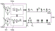
Fig. 1 illustrates the principles of ATIS.
The pixels 101 constituting the matrix of the sensor comprise two photosensitive elements 102a, 102b, such as photodiodes, connected to electronic detection circuits 103a, 103b, respectively.
When the intensity of light received by the photodiode 102a changes from a predetermined amount, the sensor 102a and the circuit 103a generate a pulse P0。
The pulse P marking the change in light intensity0The electronic circuit 103b connected to the other photodiode 102b is triggered. Then, once the photodiode 102b receives a given amount of light intensity (photon count), the circuit 103b generates a first pulse P1Then generating a second pulse P2。
Pulse P1And pulse P2Time difference betweenδ t and the occurrence of just pulse P0The intensity of light received by the pixel 101 is then inversely proportional.
The asynchronous information from the ATIS comprises two combined pulse sequence sequences per pixel (104): first pulse sequence P0Indicating the moment when the light intensity varies outside the detection threshold, and a second sequence consisting of pulses P1And P2The time difference deltat thereof represents the corresponding light intensity or gray level.
Thus, the event e (p, t) from the pixel 101 at position p in the ATIS matrix includes two types of information: by pulses P0Given the position of (a), time-dependent information given the time t of the event, and the pulse P1And P2The time difference δ t between them.
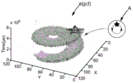
The event of the pixel can then be placed in a three-dimensional spatial/temporal representation, as shown in FIG. 2. In this figure, each point p can identify an event e (p, t) at the moment t of the horizontal asynchronous generation of the pixel p of the sensor, by the movement of the star rotating at a constant angular velocity, represented in the graph of the box a, which represents The distribution of the major part of the spots is close to the surface substantially in the form of a spiral. Furthermore, the figure shows a certain number of events spaced from the helicoid at a certain distance for measuring events that do not correspond to the actual movement of the star. These events result from the acquisition of noise.
Then, the event e (p, t) can be determined by all the following information:

in the formula: c denotes the spatial area of the sensor, pol denotes the polarity, denotes the direction of the change in brightness (e.g. 1 for increasing or-1 for decreasing), and I (p, t) denotes the light intensity signal at point p at time t.
The light intensity signal may thus be a sequence of all combined pulsesColumn 104, as shown in FIG. 1. If t isuIndicates the time of occurrence of the event, and te+,uAnd te-,uThe difference therebetween represents a value inversely proportional to the intensity of received light, and I (p, t) may be δ (t-t)u)+δ(t-te+,u)+δ(t-te-,u) The manner of (1) encodes the intensity with three dirac deltas. The pixel intensity signal at coordinate p thus enables temporal encoding of luminance information. This information can come directly from the electronic circuitry of the sensor with a minimum of conversion.
Fig. 3 is an example of calculating luminance components of two points p and q of two independent sensors u and v.
To determine whether the two points p and q of the two sensors correspond to the same point in the observed scene, it is assumed that the surface comprising the observed scene is a lambertian surface (in other words, a surface whose brightness is the same regardless of the angle of observation).
Thus, for these surfaces, the light intensity of both sensors must be the same at the same time, i.e. Iu(p,t)=Iv(q,t)。
For example, it is possible to calculate the two signals Iu(p, t) and IvCorrelation between (q, t).
In order to be able to simply compare the dirac-combined light intensity signals, it is advantageously possible to use a non-empty support kernel gσ(t) convolving the signals. Then, two signals can be calculated And
And the correlation between them.
Furthermore, it is beneficial not to limit the comparison of two single points and also to take into account the points located close to p and q (in other words, the locations are spaced from p or q by a predetermined distance, a distance being a mathematical term): all points close to p define setvu(p) the point with proximity to q defines setvv(q) (N is the cardinality of these sets). Therefore, the temperature of the molten metal is controlled,the luminance component may be expressed as follows:

of course, ω can be defined by the convolution function of all points located near p or q To reduce the integration terminal:

finally, equations using more than two sensors can be generalized. For example, for Q sensors { u, v, w, … }, one can write:

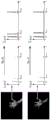
figure 4c shows cards 401 and 402 generated using separate asynchronous sensors.
To generate these cards, the function S may be defined as a sum, for each event of a given pixel p And for a given polarity pol, at a given time t, its language primitive is
 In the formula: h is a predetermined value and θ is a predetermined factor and corresponds to the speed of reduction of the language primitive.
The "sum" of the language primitives can also be mathematically viewed as a convolution:
its language primitive is (or, more generally, any decreasing function),
its signal includes occurrence of an event Each time t ofpDirac (r).
By way of illustration, fig. 4a shows three pixels p of a sensor1、p2And p3Three possibilities of active signal t → S (for a given polarity value pol).
In the absence of an event, S (p)1,t)、S(p2T) or S (p)3And t) has a value of zero. However, upon the occurrence of the polarity event pol (e.g., 410), at pixel p1,S(p1T), takes a predetermined threshold value (here h, which value h may be unity).
Then, an active signal S (p)1The value of t) gradually decreases, reaching 0 after this event.
For pixel p1Event 411, pixel p2Event 412 or pixel p3The same is true for event 413/414.
If the reduction of the activity signal S is linear, it is expected that any type of reduction will exhibit an exponential type of reduction:

this exponential type of reduction can be illustrated by fig. 4b (see curve 4b and event 320).
Furthermore, for the pixel under consideration (e.g., here p)4) When an event occurs, the value of function S is not negligible with respect to the value of h (e.g., event 421 is temporally close to event 422).
In one embodiment, upon the occurrence of a subsequent event 422, the value of the activity signal S may be set to just before the event 422 (i.e., h)0) The current value of S (which may be weighted) is summed with h. The curve S therefore decreases from the value h + h shown in FIG. 4b0And starting. In addition, it is also possible toAnticipating h + h0Is a predetermined value h1 (i.e., a minimum value (h)1,h+h0))。
In another embodiment, the value of the curve S is set to a value h when a subsequent event 422 occurs, and is independent of the value h0(i.e., the previous event (i.e., the subsequent event) ignoring the last event) is. In other embodiments, it is also possible to define the time as the "time of last event" defined as:
T(p,pol,i)=max(tj)|j<i
or
T(p,pol,t)=max(tj)|tj<t
In the formula: t is tjIs the time at which an event occurs for a pixel having a polarity pol pixel p.
Conceptually, p → T (p, pol, T) defines the time card for the last event of the same polarity that occurs temporally just before the reference time (i.e., T).
Thus, in other embodiments, it may be defined as p → S (p, pol, T) as a function of the set of times T (p, pol, T).
For example, p → S (p, pol, t):

in the formula: τ and h are predetermined time constants (S can be any decreasing function, time T is within the interval including the lower terminal T (p, pol, T)).
Creating a pixel card S that represents the "freshness" of the events of these pixels is beneficial because it enables it to simply represent a concept of discontinuity (i.e., events) in succession. The created card enables it to represent events that are to be translated into a simple understanding area.
Thus, its creation simplifies the processing and comparison of events.
The function S represents the "freshness" of the event that occurred for that pixel.
The cards 401 and 402 shown in fig. 4c represent the function S for a given time t and for two asynchronous sensors that can capture the motion of the same hand from two different perspectives.
The darkest dot indicates that the last event of the dot is the most recent (in other words, has the largest S value) with respect to time t.
The sharpest point indicates that the last event of said point is the farthest with respect to time t (in other words, with the smallest S value, the background of the image becomes grey, so as to make the sharpest value more prominent, although the background corresponds to a zero value of the function S).
The points of discrete darkening correspond to noise captured by the sensor.
For at date t0For each event that occurs, a motion card for pixel p can be determined. Thus, the value of each pixel p of the card is S (p, t)0)。
To determine whether two points p and q of a sensor correspond to the same point in the observed scene, it is assumed that the S values of the two sensors at respective points p and q are similar (in some limited cases, this is not necessarily the case), or S (p) ═ S (q) or at least S (p) ≈ S (q).
In this way, for example, it is possible to calculate a correlation between the two values s (p) and s (q).
Furthermore, it is beneficial not to limit the comparison of two single points, but also to take into account the points located in the vicinity of p (403) and q (404) (i.e. their positions are spaced from p or q by a predetermined distance, which is a distance in the mathematical sense): all points close to p define a set vu(p) (405), all points close to q define a set vv(q) (406) (N is the cardinality of these sets).
The association of the two cards 405 and 406 near points p and q can be determined. Further, to protect the sensor from time differences, the average values representing the optical flows 405 and 406 (respectively ) may each be subtracted And
And )。
)。
thus, for a given time t, the motion component may be expressed as follows:

in the formula: i is the set vuPoint or set v in (p)vAn index of a point in (q).
Finally, equations using more than two sensors can be generalized. For example, for Q sensors { u, v, w, … }, it can be written (using the same notation as used previously for the luminance component):

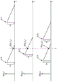
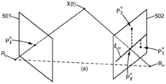
fig. 5a and 5b show examples of calculating the geometric component in embodiments of the invention.
In the case where both sensors 501 and 502 are facing the same scene (e.g., the scene includes point X (t), see FIG. 5a) and if the point of the first sensor 501 is Represents point X (t) (i.e., point)
 X (t) and RuIs aligned), epipolar lines l on the
 sensor 502 can be defineduv。
RuIs the projected center of the sensor 501, RvIs the projected center of the sensor 502.
The polar line luvIs defined as a plane (X (t), R)u,Rv) The intersection with the sensor 502.
More generally, the point p of the last sensor 501 defines the epipolar line l on the second sensor 502v(p), second sensingThe point q of the device 502 defines the epipolar line l on the first sensor 501u(q)。
Thus, the geometric components can be defined for two points p and q of the first and second sensors:

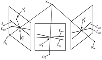
if the camera device comprises three sensors (see fig. 3b), each sensor may define two epipolar lines, which are defined by considering points on the other two sensors. The two polar lines thus cross in a straight line, which is referred to as the polarity crossing point in the following. Thus:
the point p of the first sensor and the point q of the second sensor define a polarity crossing i on the third sensorw(p,q);
The point p of the first sensor and the point r of the third sensor define a polarity crossing i on the second sensorv(p,r);
The point q of the second sensor and the point r of the third sensor define a polarity crossing i on the first sensoru(q,r)。
The geometric components can then be defined for three points p, q and r of the first, second and third sensors:

in the formula: e is the same asgA predetermined value of distance representing a maximum acceptable geometric difference.
If the camera device comprises more than three sensors (e.g. Q sensors), the previous formula can be generalized, considering the polarity intersection point of a sensor as the point located closest to the set of epipolar lines defined on that sensor by the current points of the other sensors (e.g. minimizing the sum of the distances or minimizing the square of the distances of the points of the polarity lines).

Event e (p, t) of the first sensor can also be determinedu) And event e (q, t) of the second sensorv) Time component of (a):

in the formula: e is the same astIs the number of time dimensions and represents the maximum acceptable time difference between these two events.
If the camera device includes more than three sensors (e.g., Q sensors), the previous formula can be summarized as:

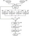
fig. 6 illustrates a flow chart presenting an embodiment according to the present invention.
Once the two sets of asynchronous events 601 and 602 from two separate asynchronous sensors have been received and compared to the same scene, two events can be selected from these sensors (step 603, by pixel p of the first sensor)iAnd time t1iAnd pixel q of the second sensorjAnd time t2jAs defined).
Once these events are selected, at least one of the following components may be determined, as previously described:
-a geometric component (step 604);
-a time component (step 605);
-a motion component (step 606);
-a luminance component (step 607).
Event e with respect to the first sensor1(pi,t1i) Aggregate, can be (e.g., by varying the index j) for many events e2(qj,t2j) Iteration is performed (test 608, output j + 1): the iteration may summarize all events of the second sensor or advantageously only a subset of these events (e.g. only position and epipolar lines or at least piEvents defined at intersections of epipolar lines separated by a predetermined geometric distance and/or only at time t1iA predetermined time distance).
At the end of the iteration (test 608, output OK), it can be determined to have event e1(pi,t1i) Event E with minimum cost function E of the set2(qj,t2j) (step 609). The cost function may be, for example, a simple sum of the previously calculated components (E ═ E)T+EM+EG+EI) Or a weighted sum (E ═ ωTET+ωMEM+ωGEG+ωIEI) (any other function involving these components is also possible).
It has been experimentally observed that a cost function taking into account the luminance component and/or the motion component should enable a significant improvement of the accuracy of the three-dimensional reconstruction.
Once minimization is implemented, point p may be connectediAnd q isj(step 610) and thus the distance or position in space of the point X (t) of the observed scene, representing the connected point p, can be calculatediAnd q isj(step 611).
The calculated distance (or position of the point x (t) in space) is then returned 612.
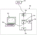
Fig. 7 illustrates an apparatus for performing an embodiment in accordance with the invention.
In this embodiment, the apparatus comprises a computer 700 comprising a memory 705 for storing instructions capable of performing the method, data from the received measurements and time data in order to perform the different steps of the method as described hereinbefore.
The computer additionally includes circuitry 704. The circuit may be, for example:
a processor capable of interpreting instructions in the form of a computer program, or,
-an electronic card in the silicon wafer of which the steps of the method of the invention are described, or else may be
A programmable electronic chip, such as an FPGA ("field programmable gate array") chip.
The computer includes an input interface 703 for receiving events from the sensors and an output interface 706 for providing a distance 707. Finally, to facilitate interaction with the user, the computer may include a screen 701 and a keyboard 702. Of course, the keyboard is optional, for example, especially as part of a computer in the form of a tablet.
Further, the functional diagram shown in fig. 6 is a typical example of a program, and some instructions of the program that can be programmed for the apparatus. In this connection, fig. 6 may correspond to a flow chart of a general algorithm of a computer program in the sense of the present invention.
Of course, the invention is not limited solely to the forms of embodiment described above as examples; the invention extends to other variants.
Other embodiments are possible.
For example, the flow chart shown in FIG. 6 may also include information about event e1(pi,t1i) To link the plurality of events of the first sensor with the events of the second sensor.
Claims (10)
1. A method of three-dimensional (3D) reconstruction of a scene, the method comprising:
-receiving first asynchronous information from a first sensor having a first matrix of pixels facing a scene, the first asynchronous information comprising, for each pixel of the first matrix, a first continuous event from said pixel of the first matrix;
-receiving second asynchronous information from a second sensor having a second matrix of pixels facing the scene, the second asynchronous information comprising, for each pixel of the second matrix, a second succession of events from said pixel of the second matrix, the second sensor being separate from the first sensor;
-matching a first event among the first successive events with a second event among the second successive events according to a minimization of the cost function E;
wherein the cost function E comprises at least one component among:
-a luminance component EISaid luminance component EIDepending on at least:
-a first luminance signal I from a pixel of a first sensoruThe first luminance signal IuBy a convolution kernel gσ(t) convolution of a first luminance signal I of said pixel of said first sensoruIs dependent on (t)e-,u,te+,u) The difference between them; and the number of the first and second groups,
-a second luminance signal I from a pixel of a second sensorvSaid second luminance signal IvA second luminance signal I of said pixel of said second sensor by said convolution kernel convolutionvIs dependent on (t)e-,v,te+,v) The difference between them;
-a motion component EMSaid component of motion EMDepending on at least:
-a time value associated with an occurrence of an event at a spatial position spaced apart from a pixel of the first sensor by a predetermined distance;
-a time value associated with an occurrence of an event at a spatial position spaced apart from a pixel of the second sensor by a predetermined distance.
2. The method of claim 1, wherein the cost function E additionally comprises:
-a time component ETSaid time component ETDepends on the difference between:
-a time value of an event with respect to the first sensor;
-a time value of an event with respect to the second sensor.
3. The method according to any of the preceding claims, wherein the cost function E additionally comprises:
geometric component EGSaid geometric component EGDepending on:
-a spatial distance from a pixel of the second sensor at the epipolar line or at an intersection of the epipolar lines defined by at least one pixel of the first sensor.
4. The method of claim 1, wherein the luminance signals of the pixels of the first sensor and the pixels of the second sensor comprise maxima, the occurrence of the luminance change is time-coded, and the convolution kernel is a predetermined gaussian variance.
5. The method of claim 1, wherein the luminance component EIIt additionally depends on:
-a luminance signal of a pixel of the first sensor, the spatial position of the luminance signal being spaced from the first pixel of the first sensor by a predetermined distance, the luminance signal of the pixel of the first sensor being convolved with a convolution kernel; and the number of the first and second groups,
-a luminance signal of a pixel of the second sensor, the spatial position of the luminance signal being spaced from a second pixel of the second sensor by a predetermined distance, the luminance signal of the pixel of the second sensor being convolved with the convolution kernel.
6. Method according to claim 1, characterized in that said motion component EMDepending on:
-average value of time values related to occurrence of pixel events of the first sensor The spatial location of the event is spaced a predetermined distance from the pixels of the first sensor;
-average value of time values related to occurrence of pixel events of the second sensor The spatial location of the event is spaced a predetermined distance from the pixels of the second sensor.
7. Method according to claim 1, characterized in that said motion component EMDepending on, for a given time:
-for each current time value associated with the occurrence of an event whose spatial position is spaced from a pixel of the first sensor by a predetermined distance, it depends on a function value which decreases from the distance at the given time to the current time value;
-for each current time value associated with the occurrence of an event whose spatial position is spaced from a pixel of a second sensor by a predetermined distance, it depends on a function value which decreases from the distance at the given time to the current time value.
8. Method according to claim 1, characterized in that said motion component EMDepending on:
-a first convolution of a decreasing function with a signal comprising a Dirac (Dirac) of each time value correlated to the occurrence of an event whose spatial position is spaced from a pixel of the first sensor by a predetermined distance;
-a second convolution of the decreasing function with a signal comprising a Dirac (Dirac) of each time value correlated to the occurrence of an event whose spatial position is spaced from the pixel of the second sensor by a predetermined distance.
9. An apparatus for three-dimensional (3D) reconstruction of a scene, the apparatus comprising:
-an interface for receiving first asynchronous information from a first sensor having a first matrix of pixels facing a scene, the first asynchronous information comprising, for each pixel of the first matrix, a first continuous event from said pixel of the first matrix;
-an interface for receiving second asynchronous information from a second sensor having a second matrix of pixels facing the scene, the second asynchronous information comprising, for each pixel of the second matrix, a second succession of events from said pixel of the second matrix, the second sensor being separate from the first sensor;
-a processor adapted to match a first event from the first succession of events with a second event from the second succession of events according to a minimization of a cost function E;
wherein the cost function E comprises at least one component among:
-a luminance component EISaid luminance component EIDepending on at least:
-a first luminance signal I from a pixel of a first sensoruThe first luminance signal IuBy a convolution kernel gσ(t) convolution of a first luminance signal I of said pixel of said first sensoruIs dependent on (t)e-,u,te+,u) The difference between them; and the number of the first and second groups,
-a second luminance signal I from a pixel of a second sensorvSaid second luminance signal IvA second luminance signal I of said pixel of said second sensor by said convolution kernel convolutionvIs dependent on (t)e-,v,te+,v) The difference between them;
-a motion component EMSaid component of motion EMDepending on at least:
-a time value associated with an occurrence of an event at a spatial position spaced apart from a pixel of the first sensor by a predetermined distance;
-a time value associated with an occurrence of an event at a spatial position spaced apart from a pixel of the second sensor by a predetermined distance.
10. A computer readable medium carrying out the steps of the method according to any one of claims 1 to 8.
Applications Claiming Priority (3)
| Application Number | Priority Date | Filing Date | Title |
|---|---|---|---|
| FR1552154A FR3033973A1 (en) | 2015-03-16 | 2015-03-16 | METHOD FOR 3D RECONSTRUCTION OF A SCENE |
| FR1552154 | 2015-03-16 | ||
| PCT/FR2016/050575 WO2016146938A1 (en) | 2015-03-16 | 2016-03-15 | Method for the 3d reconstruction of a scene |
Publications (2)
| Publication Number | Publication Date |
|---|---|
| CN107750372A CN107750372A (en) | 2018-03-02 |
| CN107750372B true CN107750372B (en) | 2021-12-10 |
Family
ID=53879566
Family Applications (1)
| Application Number | Title | Priority Date | Filing Date |
|---|---|---|---|
| CN201680016173.XA Active CN107750372B (en) | 2015-03-16 | 2016-03-15 | Method and device for three-dimensional reconstruction of scene and computer readable medium |
Country Status (7)
| Country | Link |
|---|---|
| US (1) | US11335019B2 (en) |
| EP (1) | EP3272119B1 (en) |
| JP (1) | JP6839091B2 (en) |
| KR (1) | KR102432644B1 (en) |
| CN (1) | CN107750372B (en) |
| FR (1) | FR3033973A1 (en) |
| WO (1) | WO2016146938A1 (en) |
Families Citing this family (7)
| Publication number | Priority date | Publication date | Assignee | Title |
|---|---|---|---|---|
| CN108764078B (en) * | 2018-05-15 | 2019-08-02 | 上海芯仑光电科技有限公司 | A kind of processing method and calculating equipment of event data stream |
| CN108765487B (en) | 2018-06-04 | 2022-07-22 | 百度在线网络技术(北京)有限公司 | Method, device, equipment and computer readable storage medium for reconstructing three-dimensional scene |
| EP3690736A1 (en) | 2019-01-30 | 2020-08-05 | Prophesee | Method of processing information from an event-based sensor |
| EP3694202A1 (en) | 2019-02-11 | 2020-08-12 | Prophesee | Method of processing a series of events received asynchronously from an array of pixels of an event-based light sensor |
| CN111369482B (en) * | 2020-03-03 | 2023-06-23 | 北京市商汤科技开发有限公司 | Image processing method and device, electronic equipment and storage medium |
| WO2022050279A1 (en) | 2020-09-07 | 2022-03-10 | ファナック株式会社 | Three-dimensional measurement device |
| WO2022113877A1 (en) | 2020-11-25 | 2022-06-02 | ファナック株式会社 | Three-dimensional-measurement device and three-dimensional-measurement method |
Citations (5)
| Publication number | Priority date | Publication date | Assignee | Title |
|---|---|---|---|---|
| CN103533234A (en) * | 2012-07-05 | 2014-01-22 | 三星电子株式会社 | Image sensor chip, method of operating the same, and system including the image sensor chip |
| CN103813156A (en) * | 2012-11-02 | 2014-05-21 | 三星电子株式会社 | Motion sensor array device and depth sensing system and methods of using the same |
| CN104205822A (en) * | 2011-12-08 | 2014-12-10 | 皮埃尔和玛利居里大学(巴黎第六大学) | Method of 3D reconstruction of a scene calling upon asynchronous sensors |
| CN104205169A (en) * | 2011-12-21 | 2014-12-10 | 皮埃尔和玛利居里大学(巴黎第六大学) | Method of estimating optical flow on the basis of an asynchronous light sensor |
| CN104346427A (en) * | 2013-07-29 | 2015-02-11 | 三星电子株式会社 | Apparatus and method for analyzing image including event information |
Family Cites Families (7)
| Publication number | Priority date | Publication date | Assignee | Title |
|---|---|---|---|---|
| KR100731350B1 (en) * | 2005-07-26 | 2007-06-21 | 삼성전자주식회사 | The apparatus which compensates the spatial uniformity and method thereof |
| US8290250B2 (en) * | 2008-12-26 | 2012-10-16 | Five Apes, Inc. | Method and apparatus for creating a pattern recognizer |
| US8797387B2 (en) * | 2011-04-27 | 2014-08-05 | Aptina Imaging Corporation | Self calibrating stereo camera |
| EP2574511B1 (en) * | 2011-09-30 | 2016-03-16 | Honda Research Institute Europe GmbH | Analyzing road surfaces |
| KR20140095793A (en) * | 2013-01-25 | 2014-08-04 | 삼성디스플레이 주식회사 | Method and system for evaluating panel mura |
| US10055013B2 (en) * | 2013-09-17 | 2018-08-21 | Amazon Technologies, Inc. | Dynamic object tracking for user interfaces |
| KR101861515B1 (en) * | 2016-04-21 | 2018-05-25 | 송경희 | Flow rate calculation method incident to rotation velocity and head-setting in water supply pressurizing booster pump system |
-
2015
- 2015-03-16 FR FR1552154A patent/FR3033973A1/en active Pending
-
2016
- 2016-03-15 CN CN201680016173.XA patent/CN107750372B/en active Active
- 2016-03-15 KR KR1020177029337A patent/KR102432644B1/en active IP Right Grant
- 2016-03-15 EP EP16713966.6A patent/EP3272119B1/en active Active
- 2016-03-15 JP JP2017549009A patent/JP6839091B2/en active Active
- 2016-03-15 US US15/556,596 patent/US11335019B2/en active Active
- 2016-03-15 WO PCT/FR2016/050575 patent/WO2016146938A1/en active Application Filing
Patent Citations (5)
| Publication number | Priority date | Publication date | Assignee | Title |
|---|---|---|---|---|
| CN104205822A (en) * | 2011-12-08 | 2014-12-10 | 皮埃尔和玛利居里大学(巴黎第六大学) | Method of 3D reconstruction of a scene calling upon asynchronous sensors |
| CN104205169A (en) * | 2011-12-21 | 2014-12-10 | 皮埃尔和玛利居里大学(巴黎第六大学) | Method of estimating optical flow on the basis of an asynchronous light sensor |
| CN103533234A (en) * | 2012-07-05 | 2014-01-22 | 三星电子株式会社 | Image sensor chip, method of operating the same, and system including the image sensor chip |
| CN103813156A (en) * | 2012-11-02 | 2014-05-21 | 三星电子株式会社 | Motion sensor array device and depth sensing system and methods of using the same |
| CN104346427A (en) * | 2013-07-29 | 2015-02-11 | 三星电子株式会社 | Apparatus and method for analyzing image including event information |
Non-Patent Citations (2)
| Title |
|---|
| Asynchronous Event-Based Binocular Stereo Matching;Paul Rogister,et al.;《IEEE TRANSACTIONS ON NEURAL NETWORKS AND LEARNING SYSTEMS》;20120229;第23卷(第2期);全文 * |
| Event-Based Stereo Matching Approaches for Frameless Address Event Stereo Data;Jurgen Kogler,et al.;《Springer》;20111231;全文 * |
Also Published As
| Publication number | Publication date |
|---|---|
| KR20180020952A (en) | 2018-02-28 |
| FR3033973A1 (en) | 2016-09-23 |
| CN107750372A (en) | 2018-03-02 |
| US20180063506A1 (en) | 2018-03-01 |
| KR102432644B1 (en) | 2022-08-16 |
| EP3272119A1 (en) | 2018-01-24 |
| EP3272119B1 (en) | 2021-11-10 |
| WO2016146938A1 (en) | 2016-09-22 |
| US11335019B2 (en) | 2022-05-17 |
| JP6839091B2 (en) | 2021-03-03 |
| JP2018516395A (en) | 2018-06-21 |
Similar Documents
| Publication | Publication Date | Title |
|---|---|---|
| CN107750372B (en) | Method and device for three-dimensional reconstruction of scene and computer readable medium | |
| Gehrig et al. | E-raft: Dense optical flow from event cameras | |
| Weikersdorfer et al. | Event-based 3D SLAM with a depth-augmented dynamic vision sensor | |
| Rueckauer et al. | Evaluation of event-based algorithms for optical flow with ground-truth from inertial measurement sensor | |
| JP6226876B2 (en) | Method for estimating optical flow based on asynchronous optical sensors | |
| US5818959A (en) | Method of producing a three-dimensional image from two-dimensional images | |
| US10302424B2 (en) | Motion contrast depth scanning | |
| EP3271869B1 (en) | Method for processing an asynchronous signal | |
| EP3622481B1 (en) | Method and system for calibrating a velocimetry system | |
| US10706564B2 (en) | Systems, methods, and media for determining object motion in three dimensions from light field image data | |
| Kondermann | Ground truth design principles: an overview | |
| JP4843544B2 (en) | 3D image correction method and apparatus | |
| Schraml et al. | An event-driven stereo system for real-time 3-D 360 panoramic vision | |
| Muglikar et al. | Event guided depth sensing | |
| Mangalore et al. | Neuromorphic fringe projection profilometry | |
| Liu et al. | Motion robust high-speed light-weighted object detection with event camera | |
| WO2020169834A1 (en) | Three-dimensional imaging and sensing using a dynamic vision sensor and pattern projection | |
| Loktev et al. | Image Blur Simulation for the Estimation of the Behavior of Real Objects by Monitoring Systems. | |
| Liu et al. | Outdoor camera calibration method for a GPS & camera based surveillance system | |
| Gottfried et al. | Time of flight motion compensation revisited | |
| CN115598744A (en) | High-dimensional light field event camera based on micro-lens array and extraction method | |
| CN111866493B (en) | Image correction method, device and equipment based on head-mounted display equipment | |
| Chaumont et al. | Robust and real-time 3d-face model extraction | |
| JP3900353B2 (en) | 3D position measurement system and 3D position measurement method | |
| US20240046569A1 (en) | Three dimensional rendering systems and methods from monocular image |
Legal Events
| Date | Code | Title | Description |
|---|---|---|---|
| PB01 | Publication | ||
| PB01 | Publication | ||
| SE01 | Entry into force of request for substantive examination | ||
| SE01 | Entry into force of request for substantive examination | ||
| GR01 | Patent grant | ||
| GR01 | Patent grant |