CN107745822B - Crosswind landing control method for unmanned aerial vehicle - Google Patents
Crosswind landing control method for unmanned aerial vehicle Download PDFInfo
- Publication number
- CN107745822B CN107745822B CN201710852712.XA CN201710852712A CN107745822B CN 107745822 B CN107745822 B CN 107745822B CN 201710852712 A CN201710852712 A CN 201710852712A CN 107745822 B CN107745822 B CN 107745822B
- Authority
- CN
- China
- Prior art keywords
- control
- angle
- deviation
- course
- landing
- Prior art date
- Legal status (The legal status is an assumption and is not a legal conclusion. Google has not performed a legal analysis and makes no representation as to the accuracy of the status listed.)
- Active
Links
- 238000000034 method Methods 0.000 title claims abstract description 59
- 238000005096 rolling process Methods 0.000 claims abstract description 16
- 238000012937 correction Methods 0.000 claims abstract description 10
- 238000004422 calculation algorithm Methods 0.000 claims description 11
- 238000012545 processing Methods 0.000 claims description 6
- 238000013461 design Methods 0.000 description 7
- 238000004364 calculation method Methods 0.000 description 4
- 230000000694 effects Effects 0.000 description 4
- 238000004088 simulation Methods 0.000 description 4
- 238000013459 approach Methods 0.000 description 2
- 230000015572 biosynthetic process Effects 0.000 description 2
- 238000010586 diagram Methods 0.000 description 2
- 238000003786 synthesis reaction Methods 0.000 description 2
- RZVHIXYEVGDQDX-UHFFFAOYSA-N 9,10-anthraquinone Chemical compound C1=CC=C2C(=O)C3=CC=CC=C3C(=O)C2=C1 RZVHIXYEVGDQDX-UHFFFAOYSA-N 0.000 description 1
- 230000002411 adverse Effects 0.000 description 1
- 238000009795 derivation Methods 0.000 description 1
- 239000000203 mixture Substances 0.000 description 1
- 230000036544 posture Effects 0.000 description 1
- 230000003068 static effect Effects 0.000 description 1
- 238000006467 substitution reaction Methods 0.000 description 1
- 238000012360 testing method Methods 0.000 description 1
- 238000012795 verification Methods 0.000 description 1
Images


Classifications
-
- B—PERFORMING OPERATIONS; TRANSPORTING
- B64—AIRCRAFT; AVIATION; COSMONAUTICS
- B64D—EQUIPMENT FOR FITTING IN OR TO AIRCRAFT; FLIGHT SUITS; PARACHUTES; ARRANGEMENT OR MOUNTING OF POWER PLANTS OR PROPULSION TRANSMISSIONS IN AIRCRAFT
- B64D45/00—Aircraft indicators or protectors not otherwise provided for
- B64D45/04—Landing aids; Safety measures to prevent collision with earth's surface
Landscapes
- Engineering & Computer Science (AREA)
- Aviation & Aerospace Engineering (AREA)
- Control Of Position, Course, Altitude, Or Attitude Of Moving Bodies (AREA)
Abstract
The invention relates to an unmanned aerial vehicle crosswind landing control method, which comprises the following steps: establishing deviation rectifying maneuvering control for landing of the unmanned aerial vehicle, wherein the maneuvering control for deviation rectifying is used for reducing the drift angle beta of the airplanew(ii) a Adding course to the current-rectifying maneuvering controlThe maneuvering reservation control is used for reducing the impact of the deviation correction maneuvering on the airplane lateral deviation control; adding sideslip angle limitation in the motor control of the bias correction motor, and preventing the lateral load of the unmanned aerial vehicle from exceeding the limit; and a rolling angle authority limit is required to be added into a transverse control branch of the deviation rectifying machine so as to avoid the ground rubbing of the wings caused by the near-ground rolling deviation rectifying. According to the unmanned aerial vehicle crosswind landing control method, the crosswind correction and the rectifying flow maneuver are combined in the landing control process, the matching problem of the coordinated control and the rectifying flow maneuver control in the landing process is solved, the safe landing under the condition that the rolling attitude is limited/the sideslip is limited is realized, and the safety of the unmanned aerial vehicle crosswind landing process can be obviously improved.
Description
Technical Field
The invention belongs to the technical field of unmanned aerial vehicle flight control, and particularly relates to a crosswind landing control method for an unmanned aerial vehicle.
Background
The unmanned aerial vehicle is all needed to make great adjustment at flying height, speed, the configuration of landing process, still can receive influences such as ground effect pneumatics, wind field shear near the ground process of landing, therefore unmanned aerial vehicle landing process is one of the high stage of accident. The lateral wind component of the landing wind field is a very adverse effect on the landing process, and the course of the aircraft is directly disturbed under the influence of the lateral wind, so that the landing lateral deviation control of the aircraft is influenced. If the conventional sideslip method is adopted for landing, although the course of the airplane can be ensured to be aligned to the runway, the sideslip and rolling postures of the airplane need to be adjusted in a reciprocating mode to counteract the side wind effect, and the continuous adjustment of the sideslip angle and the rolling angle of the airplane causes bad disturbance to the control of the landing flight path of the airplane. Under the condition of strong crosswind, the roll angle of the balanced crosswind of the airplane may exceed the limitation of the wing roll rubbing angle, thereby affecting the flight safety. If the drift method is adopted for landing, although the reciprocating adjustment of the sideslip angle and the roll angle of the airplane can be avoided, the drift angle can cause larger lateral impact on the undercarriage in the landing and grounding process, and the risk of the crosswind landing can be increased. The invention provides a deviation rectifying flow control law framework by adopting a drift angle-based crosswind landing strategy, and the safety of the crosswind landing process can be effectively improved.
Disclosure of Invention
The invention aims to provide a crosswind landing control method for an unmanned aerial vehicle, which avoids the problem of lateral direction reciprocating operation caused by crosswind landing by a sideslip method and solves the safety problem of deviation rectification maneuvering before the grounding by a bias method.
In order to achieve the purpose, the invention adopts the technical scheme that: an unmanned aerial vehicle crosswind landing control method comprises
Establishing deviation rectifying maneuvering control for landing of the unmanned aerial vehicle, wherein the maneuvering control for deviation rectifying is used for reducing the drift angle beta of the airplanew;
Adding course maneuvering reserved control in the control of the deviation correcting maneuvering, and reducing the impact of the deviation correcting maneuvering on the control of the lateral deviation of the airplane;
adding sideslip angle limitation in the motor control of the bias correction motor, and preventing the lateral load of the unmanned aerial vehicle from exceeding the limit; and
the rolling angle authority limit is added in the transverse control branch of the deviation rectifying machine to avoid the ground rubbing of the wings caused by the near-ground rolling deviation rectifying.
Furthermore, the control quantity of the deviation rectifying motor is a course angle.
Further, before the corrected drift maneuvering control is established, a limiting function of the crosswind landing of the unmanned aerial vehicle needs to be established, and the limiting parameters include:
main wheel crossing angle intensity limiting function betagear_lim=f(G,Vy) Wherein G is the weight of the airplane and Vy is the ground sinking rate;
unmanned aerial vehicle rolling ground-wiping angle limiting function Wherein HbaseIndicating the basic height of the wing from the ground, H, at standstillrelativeThe relative height of the airplane wheel base from the airport ground is shown, and l represents the airplane wingspan length.
Further, the bias current correcting maneuvering control comprises a course angle control outer ring and a yaw angle rate control inner ring, wherein the course angle control outer ring and the yaw angle rate control inner ring are included in the bias current correcting maneuvering control
The course motion differential equation of course angle control is as follows:

yaw rate command omega for yaw rate controlyc=K_Decrab·(ψc-ψ)。
Further, omega after adding course deviation dead zoneycThe instruction resolving method comprises the following steps:
ωyc=fψDZ(ψc-ψ)·K_Decrab,
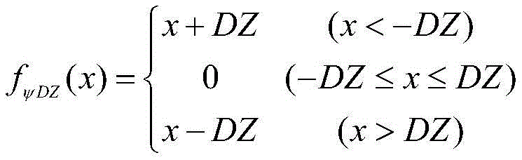
wherein the dead zone range of course deviation control is [ -DZ, DZ]Course maneuver reservation function fψDZ(x) Comprises the following steps:

wherein the parameter DZ satisfies the following condition: DZ < betagear_lim+(ψc-ψ)·ψ%,ψ% is deviation correcting flow course control overshoot.
Further, to achieve the sideslip angle limitation, a yaw rate command limitation and sideslip angle limitation function needs to be established,
due to the limitation of the yaw rate instruction, the limited yaw rate instruction omegayc.satIs composed of
Wherein the yaw rate command ωycThe clipping function of (d) may be expressed as:

determining a yaw rate limiting parameter SAT according to the maximum yaw rate control capability of the aircraft rudder course;
the sideslip limiting function is limited by two conditions of an aircraft sideslip limit value and a yaw rate limiting parameter SAT, and the sideslip limiting nonlinear function is expressed as follows:

in the above formula, -. beta.1~β1For normal maneuvering sideslip angle range, -beta2~β2Is the maximum allowable maneuvering sideslip angle range;
after the algorithm processing, a yaw rate deviation instruction delta omega is obtainedycComprises the following steps:

further, the limiting value of the roll angle instruction in the transverse branch is based on Determining, the roll angle command limit function is described as follows:

the unmanned aerial vehicle crosswind landing control method combines the lateral deviation correction and the rectification maneuvering in the landing control process, and solves the matching problem of the coordination control and the rectification maneuvering control in the landing process. The control law framework provided by the invention can solve the matching problem of bias current rectifying maneuver and lateral deviation correction in the landing and grounding process, realizes safe landing under the condition of limited rolling attitude/limited lateral slip, and can remarkably improve the safety of the unmanned aerial vehicle in the lateral wind landing process.
Drawings
The accompanying drawings, which are incorporated in and constitute a part of this specification, illustrate embodiments consistent with the invention and together with the description, serve to explain the principles of the invention.
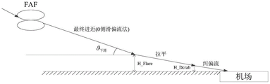
FIG. 1 is a schematic illustration of an aircraft landing under crosswind conditions according to the present invention;
FIG. 2 is a diagram of the corrective flow control law of the present invention;
FIG. 3 is a side wind landing integrity control law architecture of the present invention;
FIG. 4 is a cross-sectional view of a typical crosswind landing configuration of the present invention;
FIG. 5 is a simulation result comparing a crosswind landing example of the prior art with the method of the present invention.
Detailed Description
In order to make the implementation objects, technical solutions and advantages of the present invention clearer, the technical solutions in the embodiments of the present invention will be described in more detail below with reference to the accompanying drawings in the embodiments of the present invention.
The invention provides a crosswind landing control method of an unmanned aerial vehicle, which is suitable for a large-span unmanned aerial vehicle, wherein the crosswind landing control method combines the lateral deviation correction and the deviation-correcting maneuver in the landing control process of the unmanned aerial vehicle, and solves the matching problem of the coordination control and the deviation-correcting maneuver control in the landing process.
The method for controlling the crosswind landing of the unmanned aerial vehicle can comprise the following steps:
firstly, the method comprises the following steps: establishing landing parameter limiting function
The main limiting functions of crosswind landing mainly comprise a main wheel crossing angle intensity limiting function and an airplane rolling ground rubbing angle limiting function.
The angle of intersection of the main wheels is defined as the angle between the direction of ground speed and the main wheels, the limit of which can be defined by a limiting function betagear_lim=f(G,Vy) Describing, the crossing angle limit value βgear_limGround sinking rate V along with aircraft weight GyIn relation, specific parameters can be given according to the strength design result of the landing gear.
Aircraft rolling wiping ground limiting angle gammaflare_limApplicable function Is calculated to obtainbaseIndicating the basic height of the wing from the ground, H, at standstillrelativeThe relative height of the airplane wheel base from the airport ground is shown, and l represents the airplane wingspan length. Determining conditions for wing span and landing gear layout of airplaneThe height H of the bottom of the airplane wheel relative to the ground of the airportrelativeThe higher the roll scrub limit angle.
II, secondly: rectification flow control law design
The invention adopts a drift method to complete the lateral direction control at the initial stage of the aircraft landing, and the landing schematic diagram of the drift method is shown in figure 1. If the aircraft is exposed to left wind VwThe disturbance and drift method realizes that the aircraft nose always points to the incoming flow direction by instructing the sideslip angle to be 0 degree, and the drift angle beta is formed between the aircraft course and the ground speed directionw. The control target of the deviation rectification maneuver is to reduce the drift angle of the airplane so as to reduce the impact of the drift landing on the landing gear. In the invention, the control quantity of the deviation correcting motor is determined as the course angle, and the course deviation is eliminated while the deviation angle can be effectively reduced, so that the design can simultaneously reduce the influence of the course deviation on the land sliding lateral deviation control.
The deviation rectifying flow control law consists of a course angle control outer ring and a yaw angle rate control inner ring, and the rudder is applied to the heading direction to realize the direct control of the yaw angle. According to the aircraft course moment equation

If a rudder is adoptedyIs the main control quantity of course, aileronxBy matching with the coordination control, the yaw rate omega can be realizedyThe effective control of (2). In the above formula, omegayWhich is indicative of the yaw rate, represents the large derivative of yaw moment to side slip, beta represents the side slip angle,
 representing the large derivative, ω, of the yaw moment with respect to the roll angular ratexThe roll-angle rate is shown as,
 representing yaw moment pairLarge derivative of yaw rate, ωyWhich is indicative of the yaw rate,
 indicating a large derivative of the yaw moment produced by the aileron,xthe deviation of the aileron is shown,
 indicating a large derivative of the yaw moment produced by the rudder,yshows rudder deflection, Δ MyconstRepresenting a heading asymmetry moment.
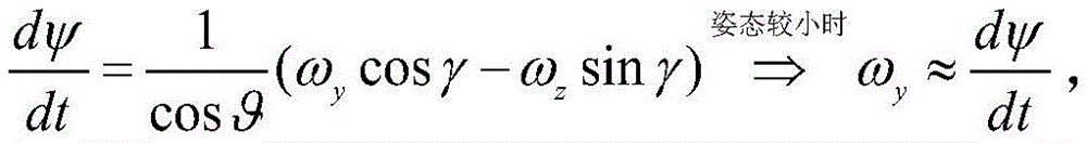
According to the differential equation of course motion, the following steps are obtained:
yaw rate ω when roll angle γ and pitch angle θ are smallyApproximately the derivative of the yaw angle. In the above formula, phi denotes the heading angle, omegazRepresenting the pitch rate.
Thus, the control system can form a control framework of yaw angle-yaw angle rate-yaw control moment. According to the above derivation, the The typical control framework of the control law, and then the design of each loop of the control law is completed.
FIG. 2 shows the principle of the deviation control law, and the lateral control can calculate the lateral operating moment M according to the lateral deviation informationxcCompleting the track control of the horizontal plane; the course control is based on the given course command psicThe deviation between the runway landing course and the course feedback psi is resolved by the course deviation proportional gain K _ Decrab to obtain a yaw rate instruction omegaycYaw rate command ωycWith yaw rate omegayThe feedback deviation passes through a non-static control law (such as a proportional integral PI algorithm), and finally a course control torque command M is formedycThe algorithm is described as follows:
yaw rate command ω in the above equationyc=K_Decrab·(ψc-ψ),KPTo proportional gain, KIIs integral gain, s is differential operator;
the horizontal and course control torque command is finally subjected to an efficiency distribution algorithm to obtain an aileron commandxWith rudder instructiony。
Thirdly, the method comprises the following steps: course maneuvering reservation algorithm
In the actual engineering design, the full-authority deviation rectifying motor may cause the conditions of large rudder consumption and large sideslip, and the long-time sideslip effect can bring additional lateral deviation disturbance. Considering the limitation range of the intersection angle of the main landing gear, the heading deviation can not be actively corrected within the safety range, so that the airplane can finish land grounding with the safe deviation angle, and the impact of the deviation correcting maneuver on the lateral deviation control of the airplane is reduced. Omega added with course deviation dead zoneycThe instruction resolving method comprises the following steps: omegayc=fψDZ(ψc- ψ) K-Decrab wherein the heading deviation control dead zone range is [ -DZ, DZ]Course maneuver reservation function fψDZ(x) Can be expressed as:

the selection of the parameter DZ needs to comprehensively consider the limitation of the crossing angle of the undercarriage and the overshoot of course control, and the selection of the parameter DZ needs to meet the following basic conditions: DZ < betagear_lim+(ψc-ψ)·ψ%
In the above formulaψ% is deviation correcting flow course control overshoot.
Fourthly, the method comprises the following steps: rectifying current motor sideslip limitation
The sideslip angle is in an open-loop state in the whole deviation-correcting flow maneuvering process, considering that the aerodynamic characteristics of the airplane entering a large sideslip state are deteriorated in different degrees, and meanwhile, the lateral load of the airplane is possibly over-limited due to the large sideslip angle state, so that the sideslip angle limit is required to be added into the deviation-correcting flow control law as an important protection algorithm. In order to realize the sideslip angle limitation, the design of the yaw rate instruction limitation and the sideslip angle limitation function needs to be completed.
Considering the limitation of the yaw rate instruction, the limited yaw rate instruction omegayc.satIs composed of
Wherein the yaw rate command ωycThe clipping function of (d) may be expressed as:

the yaw rate limiting parameter SAT may be determined based on the maximum yaw rate control capability of the aircraft rudder heading.
The sideslip limiting function needs to comprehensively consider two conditions of an airplane sideslip limiting value and a yaw rate limiting parameter SAT, and the sideslip limiting nonlinear function is expressed as follows:

in the above formula, -. beta.1~β1For normal maneuvering sideslip angle range, -beta2~β2Is the maximum allowable maneuvering sideslip angle range. After the algorithm processing, a yaw rate deviation instruction delta omegaycComprises the following steps:

fifthly: yaw control law design for roll-limited conditions
As the height of the airplane is reduced and limited by the rolling ground rubbing angle of the airplane, the authority of the available rolling angle of the airplane is reduced. And a roll angle authority limit is required to be added into the deviation rectifying transverse control branch so as to avoid wing ground rubbing caused by near-ground roll deviation rectification. The limiting value of the roll angle instruction in the transverse branch in the control law is based on Determining, the roll angle command limit function is described as follows:

the detailed architecture of the whole control law is shown in fig. 3, and the landing control consists of three parts, namely vertical plane trajectory control, horizontal plane trajectory control and yaw branch control. And controlling the landing glide slope to track and level by controlling the plumb plane. The horizontal plane track control is used for completing the lateral deviation control, the horizontal plane track tracking function of the airplane is realized, and the control law obtains the ground speed direction increment instruction psi according to the lateral deviation calculationVdcAnd heading angle command psicIn the direction psi with the ground speedVdAfter synthesis, the course proportion gain KψAnd then obtaining the instruction roll angle. Considering that large-span aircraft do not allow large roll angles to occur during the near-earth process, the limit value gamma of the near-earth roll angle is setLimReduced to a constant value of 3 deg.. Roll angle command gamma subjected to amplitude limiting processingcAfter being integrated with the roll angle gamma, the mixture is subjected to roll proportional gain KγObtaining a roll angular rate instruction omega after processingxc. Roll angular rate command omegaxcWith roll angle rate omegaxAfter synthesis, the transverse control moment instruction M is obtained after calculation by a proportional integral algorithmxc. The yawing branch consists of an aerial sideslip command and a deviation rectifying flow. Air flight course control law sideslipping by instruction betacAfter being integrated with the sideslip angle beta, the yaw control moment instruction M is obtained through calculation of a proportional integral PI controllerycAnd controlling the airplane to fly coordinately without sideslip. Before the aircraft is grounded, the course is switched to a deviation-correcting flow control law, and the course angle command psicAfter being integrated with the course psi, the navigation angle speed command omega is obtained through the processing of a course maneuvering reservation algorithm and the proportional gain K _ Decrabyc(ii) a The actual yaw rate control capability of the airplane is considered, and the actual yaw rate command omega is obtained after amplitude limitingyc.satFeedback of ω from yaw rateyAnd obtaining yaw rate command deviation delta omega after the sideslip limiting branch is synthesizedycAnd obtaining a course control moment instruction M after calculation by a proportional integral PI algorithmyc。
The whole crosswind landing of the airplane is divided into three stages according to the height of the airplane relative to an airport, and the vertical plane trajectory is schematically shown in figure 4. In the final approach stage, the vertical plane completes accurate tracking control of the lower slideway, the horizontal plane completes accurate tracking control of lateral deviation, and the yaw branch completes 0 lateral deviation control; the leveling control is completed on the vertical plane in the leveling stage, the sinking rate of the airplane is reduced, the lateral deviation accurate tracking control is completed on the horizontal plane, and the 0-lateral-sliding control is completed on the navigation branch; and in the rectification flow stage, the vertical plane is leveled, the sinking rate of the airplane is reduced, the horizontal plane is subjected to lateral deviation control under the condition that the rolling angle is limited, and the yaw branch is subjected to rectification flow maneuver, so that the course of the airplane is aligned to the center line of the runway.
As shown in fig. 5, the simulation results of the drift method crosswind landing and the sideslip method crosswind landing are compared, and it can be known from the simulation comparison results that: the control method of the invention always keeps the sideslip angle near 0 degree in the final approach process, the disturbance of the roll angle is small, and the additional roll angle is not needed to balance the lateral force under the condition of lateral wind; the rectification motor before grounding is quick and effective, the drift angle of the airplane is basically eliminated when the airplane is grounded, and no obvious lateral deviation disturbance appears in the subsequent ground sliding. In the sideslip method, the course of the airplane is ensured to be aligned to a runway by establishing a sideslip angle, and the airplane needs to roll right to balance the sideslip force caused by sideslip; when the airplane is leveled, in order to avoid the rubbing of the wings, the roll angle is reduced to 3 degrees, at the moment, the 3-degree roll angle is not enough to balance the influence of crosswind, the airplane deviates leftwards, and the airplane slips to be greatly adjusted in a reciprocating mode due to the additional course deviation and the lateral deviation after the airplane is grounded. Compared with simulation, the control method of the drift method and the rectifying maneuver can effectively improve the safety of the large-span unmanned aerial vehicle in the side wind landing.
The invention provides an unmanned aerial vehicle crosswind landing control method which combines the lateral deviation correction and the deviation rectification maneuver in the aircraft landing control process, and solves the matching problem of the coordination control and the deviation rectification maneuver control in the landing process. The control law framework provided by the invention can solve the matching problem of bias current rectifying maneuver and lateral deviation correction in the landing grounding process, and realizes safe landing under the condition of limited rolling attitude/limited lateral slip. Through test flight verification, the set of technology can obviously improve the safety of the unmanned aerial vehicle crosswind landing process.
The above description is only for the best mode of the present invention, but the scope of the present invention is not limited thereto, and any changes or substitutions that can be easily conceived by those skilled in the art within the technical scope of the present invention are included in the scope of the present invention. Therefore, the protection scope of the present invention shall be subject to the protection scope of the appended claims.
Claims (5)
1. An unmanned aerial vehicle crosswind landing control method is characterized by comprising the following steps
Establishing a limit function for crosswind landing of the unmanned aerial vehicle, wherein the limit function comprises:
main wheel crossing angle intensity limiting function betagear_lim=f(G,Vy) Wherein G is the weight of the airplane and Vy is the ground sinking rate;
unmanned aerial vehicle rolling ground-wiping angle limiting function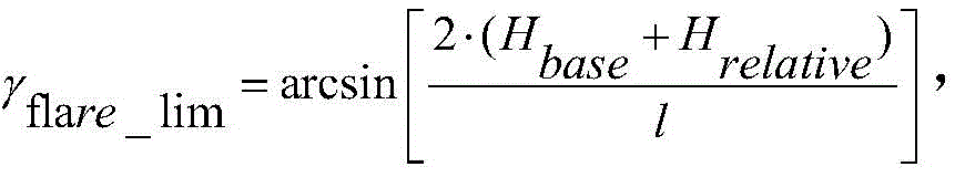 Wherein HbaseIndicating the basic height of the wing from the ground, H, at standstillrelativeThe relative height between the wheel base of the airplane and the ground of the airport is represented, and l represents the wingspan length of the airplane;
establishing deviation rectification maneuvering control for landing of unmanned aerial vehicle with controlled quantity as course angle, wherein the deviation rectification maneuvering control is used for reducing the aircraft deviation angle betaw;
Adding course maneuvering reserved control in the control of the deviation correcting maneuvering, and reducing the impact of the deviation correcting maneuvering on the lateral deviation control of the airplane;
adding sideslip angle limitation in the motor control of the bias correction motor, and preventing the lateral load of the unmanned aerial vehicle from exceeding the limit; and
a roll angle authority limit is added in a transverse control branch of the deviation rectifying machine to avoid wing ground rubbing caused by near-ground roll deviation rectification.
2. The method for controlling crosswind landing of an unmanned aerial vehicle according to claim 1, wherein the bias-corrected maneuvering control comprises an outer course of course angle control and an inner course of yaw angle rate control, wherein the outer course of course angle control and the inner course of yaw rate control
The course motion differential equation of course angle control is as follows:
yaw rate command omega for yaw rate controlyc=K_Decrab·(ψc-ψ),ψcFor the heading angle command, K _ Decrab is the heading deviation proportional gain.
3. The method for controlling crosswind landing of the unmanned aerial vehicle according to claim 2, wherein ω after adding a heading deviation dead zoneycThe instruction resolving method comprises the following steps: omegayc=fψDZ(ψcPhi) K Decrab, wherein the heading deviation control dead zone range is [ -DZ, DZ]Course maneuver reservation function fψDZ(x) Comprises the following steps:
wherein the parameter DZ satisfies the following condition: DZ<βgear_lim+(ψc-ψ)·ψ%,ψ% is deviation correcting flow course control overshoot, K _ Decrab is deviation correcting flow control proportional gain, betagear_LimFor landing gear crossing angle limit, psicIs the heading angle command and psi is the heading angle.
4. The method of claim 3, wherein a yaw rate command limit and a yaw angle limit function are established to achieve the yaw angle limit,
due to the limitation of the yaw rate instruction, the limited yaw rate instruction omegayc.satIs composed of
Wherein the yaw rate command ωycThe clipping function of (d) may be expressed as:
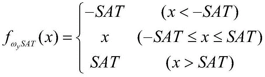
determining a yaw rate limiting parameter SAT according to the maximum yaw rate control capability of the aircraft rudder course;
the sideslip limiting function is limited by two conditions of an aircraft sideslip limit value and a yaw rate limiting parameter SAT, and the sideslip limiting nonlinear function is expressed as follows:
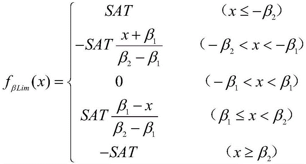
in the above formula, -. beta.1~β1For normal maneuvering sideslip angle range, -beta2~β2Is the maximum allowable maneuvering sideslip angle range;
after the algorithm processing, a yaw rate deviation instruction delta omega is obtainedycComprises the following steps:
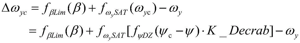
in the above formula, beta is a sideslip angle, omegayIn order to be able to determine the yaw rate,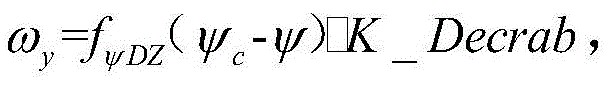 fψDZreserving a function, psi, for course maneuveringcIs the heading angle command and psi is the heading angle.
5. The method of claim 4, wherein the limitation of the roll angle command in the lateral branch is based on the value of the roll angle command in the lateral branch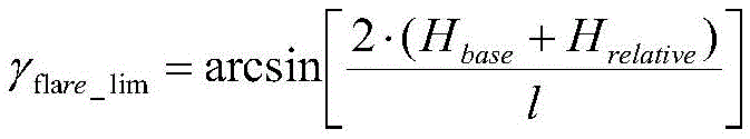 Determining, the roll angle command limit function is described as follows:

Priority Applications (1)
| Application Number | Priority Date | Filing Date | Title |
|---|---|---|---|
| CN201710852712.XA CN107745822B (en) | 2017-09-20 | 2017-09-20 | Crosswind landing control method for unmanned aerial vehicle |
Applications Claiming Priority (1)
| Application Number | Priority Date | Filing Date | Title |
|---|---|---|---|
| CN201710852712.XA CN107745822B (en) | 2017-09-20 | 2017-09-20 | Crosswind landing control method for unmanned aerial vehicle |
Publications (2)
| Publication Number | Publication Date |
|---|---|
| CN107745822A CN107745822A (en) | 2018-03-02 |
| CN107745822B true CN107745822B (en) | 2020-12-18 |
Family
ID=61254586
Family Applications (1)
| Application Number | Title | Priority Date | Filing Date |
|---|---|---|---|
| CN201710852712.XA Active CN107745822B (en) | 2017-09-20 | 2017-09-20 | Crosswind landing control method for unmanned aerial vehicle |
Country Status (1)
| Country | Link |
|---|---|
| CN (1) | CN107745822B (en) |
Families Citing this family (6)
| Publication number | Priority date | Publication date | Assignee | Title |
|---|---|---|---|---|
| CN110096070B (en) * | 2019-05-17 | 2021-08-03 | 成都飞机工业(集团)有限责任公司 | Transverse control method for unilateral missile hanging landing |
| CN111007869A (en) * | 2019-11-20 | 2020-04-14 | 中国航空工业集团公司沈阳飞机设计研究所 | Given track azimuth automatic control method |
| CN111309041B (en) * | 2020-03-05 | 2022-05-10 | 成都飞机工业(集团)有限责任公司 | Catapult-assisted take-off pull-up control method |
| CN112947527B (en) * | 2021-03-15 | 2024-11-22 | 中国商用飞机有限责任公司 | A flight control method and device for an aircraft |
| CN114675663A (en) * | 2022-03-18 | 2022-06-28 | 成都飞机工业(集团)有限责任公司 | A planning and control method for unmanned aerial vehicle landing in crosswind environment |
| CN115167494B (en) * | 2022-08-05 | 2024-11-01 | 烟台大学 | Sideslip and inclination compound turning control method of unmanned aerial vehicle |
Family Cites Families (6)
| Publication number | Priority date | Publication date | Assignee | Title |
|---|---|---|---|---|
| GB1561650A (en) * | 1976-01-29 | 1980-02-27 | Sperry Rand Corp | Aircraft control system |
| CN100568141C (en) * | 2008-03-20 | 2009-12-09 | 北京航空航天大学 | A control method for unmanned aerial vehicle roll leveling |
| CN101763116B (en) * | 2008-12-24 | 2012-12-12 | 中国科学院自动化研究所 | Side wind resistance landing flight track tracking control method based on side direction guide |
| FR2948468B1 (en) * | 2009-07-23 | 2011-09-16 | Airbus Operations Sas | METHOD AND DEVICE FOR AIDING SIDE CONTROL OF AIRCRAFT DURING AN APPROACH PHASE |
| CN104656661B (en) * | 2015-01-23 | 2017-04-19 | 南京航空航天大学 | Corporate aircraft descending and landing control method |
| CN105159308B (en) * | 2015-08-28 | 2017-12-15 | 北京控制工程研究所 | A kind of Reusable launch vehicles landing phase guides coupling design method integrated with control law |
-
2017
- 2017-09-20 CN CN201710852712.XA patent/CN107745822B/en active Active
Also Published As
| Publication number | Publication date |
|---|---|
| CN107745822A (en) | 2018-03-02 |
Similar Documents
| Publication | Publication Date | Title |
|---|---|---|
| CN107745822B (en) | Crosswind landing control method for unmanned aerial vehicle | |
| CN111610780B (en) | Automatic driving vehicle path tracking control method and device | |
| US6722610B1 (en) | Method, system, and computer program product for controlling maneuverable wheels on a vehicle | |
| CN111123967B (en) | A landing control method for fixed-wing UAV based on adaptive dynamic inverse | |
| Azinheira et al. | A backstepping controller for path‐tracking of an underactuated autonomous airship | |
| CN105159308B (en) | A kind of Reusable launch vehicles landing phase guides coupling design method integrated with control law | |
| CN109253730B (en) | Three-dimensional track online planning method and system capable of repeatedly using tail end energy management section of carrier | |
| CN115933733B (en) | A longitudinal height-velocity decoupling nonlinear control method for fixed-wing UAV | |
| CN112148029B (en) | Non-power full-automatic forced landing method for running and landing type unmanned aerial vehicle | |
| CN105857586B (en) | Method and apparatus for controlling steerable landing gear | |
| CN212965864U (en) | A conventional layout general-purpose unmanned aerial vehicle automatic take-off control system | |
| CN108369106A (en) | Prevention and recovery flight controller out of control | |
| CN101264797A (en) | A control method for unmanned aerial vehicle roll leveling | |
| CN113093774A (en) | Unmanned aerial vehicle sliding control method | |
| CN107544530A (en) | A kind of unmanned plane independently drives into or out of control method | |
| CN116339140B (en) | Composite fault-tolerant control method based on instantaneous active disturbance rejection and adaptive dynamic inversion | |
| CN106990790A (en) | A kind of anti-saturation multi-rotor aerocraft control method | |
| CN101256412A (en) | An automatic homing control method for unmanned aerial vehicles when the engine stops unexpectedly | |
| CN108089593A (en) | A kind of method of unmanned helicopter course compensation course line transition | |
| CN114675663A (en) | A planning and control method for unmanned aerial vehicle landing in crosswind environment | |
| CN115129084A (en) | Large-lateral-deviation landing deviation-correcting control method for flying wing layout unmanned aerial vehicle | |
| CN109343551A (en) | A method and system for coordinated turning control of a rotorcraft | |
| CN104656659B (en) | Shipboard aircraft ski-jump take-off automatic flight control method | |
| CN117148855A (en) | A flight control command generation method for aircraft formation maneuvering flight | |
| CN116300988A (en) | An Anti-jamming Control Strategy for Advanced Layout UAV Based on Fractional Sliding Mode |
Legal Events
| Date | Code | Title | Description |
|---|---|---|---|
| PB01 | Publication | ||
| PB01 | Publication | ||
| SE01 | Entry into force of request for substantive examination | ||
| SE01 | Entry into force of request for substantive examination | ||
| GR01 | Patent grant | ||
| GR01 | Patent grant |