CN1077225C - Mechanical starter motor - Google Patents
Mechanical starter motor Download PDFInfo
- Publication number
- CN1077225C CN1077225C CN96193224A CN96193224A CN1077225C CN 1077225 C CN1077225 C CN 1077225C CN 96193224 A CN96193224 A CN 96193224A CN 96193224 A CN96193224 A CN 96193224A CN 1077225 C CN1077225 C CN 1077225C
- Authority
- CN
- China
- Prior art keywords
- ratchet
- spring
- winding
- gear
- small gear
- Prior art date
- Legal status (The legal status is an assumption and is not a legal conclusion. Google has not performed a legal analysis and makes no representation as to the accuracy of the status listed.)
- Expired - Fee Related
Links
Images


Classifications
-
- F—MECHANICAL ENGINEERING; LIGHTING; HEATING; WEAPONS; BLASTING
- F02—COMBUSTION ENGINES; HOT-GAS OR COMBUSTION-PRODUCT ENGINE PLANTS
- F02N—STARTING OF COMBUSTION ENGINES; STARTING AIDS FOR SUCH ENGINES, NOT OTHERWISE PROVIDED FOR
- F02N5/00—Starting apparatus having mechanical power storage
- F02N5/02—Starting apparatus having mechanical power storage of spring type
Abstract
Starter motor (10) for internal combustion engines which operates mechanically using stored strain energy as the power source whereby the spring means comprises a spiral power spring (90).
Description
The present invention relates to be used for piloting engine of internal-combustion engine, particularly relate to the strain energy that will store as power source, mechanical starter motor.
Present starting arrangement is generally used motoring, and this motor must have enough big power with cranking internal combustion engine.Generally with battery as the energy, this battery can provide under 12V voltage greater than 200 amperes electric current with cranking internal combustion engine, and when the starting large diesel engine, power source should be greater than this.
Under given conditions, as overheated or cross under the cold or extremely moist condition, battery and relevant electric system thereof are impaired rapidly.Particularly like this under the particularly sub-standard or situation about at all just not having at service and repair.And under certain environment, the motor-driven starter fire-prone is used this starter as not allowing in mine.
Mechanical starter plays energy source than electric starting device more reliably for internal-combustion engine provides.
The mechanical priming device that is adopted up to now generally comprises the spring assembly of storing energy, on above-mentioned spring assembly, apply energy with it is stored in the spring assembly device and when energy storage discharges, transform energy storage provides starting pulse for described internal-combustion engine drive unit.
In the starting arrangement of described type, spring assembly comprises one group of disc spring; By artificial rotating crank repeatedly, crank is the worm screw on the rotatingshaft again, and described axle is by the center of spring, and worm screw is screwed into base plate, thereby makes the mobile end plate compression plate of the rotation spring of worm screw, and makes spring produce deformation.In case stored enough energy, energy discharged with regard to manually unclamping ratchet pawl.Spring will axially produce reaction, and described device converts axial motion to the rotation energy.Rotation can be sent to output shaft, and output shaft comprises a small gear, and this small gear is suitable for meshing the ring gear on the internal combustion engine flywheel.
This known mechanical priming device utilizes a knock-down wind to come wind spring mechanism with storing energy therein.These handles should have sizable size to apply necessary energy and to be that operation provides necessary mechanical advantage.This conversely again with the location of starter motor and directed be limited in one can the free operant wind and easily enter the position of that part of internal-combustion engine.
Compression ignition engine, for example diesel engine is particularly suitable for because in course of normal operation, not needing relevant electric power system to keep its work with this mechanical device starting.The amounts of rotation that can be used for the mechanical priming device in addition is subjected to energy storage to discharge the restriction of the front coil spring stroke that finishes.On the starter of usefulness, spring travel is again little and short.It is preferably used on many cylinders diesel engine, wherein by starting arrangement rotating crank axle, just may cause burning during crankshaft turns over a camber line.
As mentioned above, the elastic energy of storing in the disc spring discharges with the form of axial motion, and this axial motion must change into the rotational motion that is used for cranking internal combustion engine.Energy loss is very big in conversion process, and this motor must be done very firmly in to bear the axial force that spring applies.This point all increases cost and weight, increases thereby make it use price.
Therefore need a kind of mechanical priming device that improves efficient and versatility that has, this starter motor can be used for starting multiple internal-combustion engine.The weight and the low structure of cost that need the mechanical priming device to have simultaneously to alleviate.Also require this mechanical priming device to operate easily, and must not need the stock wind.
U.S. Patent No. 3127883 discloses a kind of mechanical priming device, it comprises the disc spring of stored energy, apply energy with the winding device of stored energy therein to described spring, and the drive unit that transforms stored energy, energy can provide the starting pulse of motor when discharging.But in this device, spring may excessive deformation, and needs a mechanical trip.
Main purpose of the present invention is to provide a kind of effective and safe improved spring to pilot engine.More specifically, the purpose of this invention is to provide a kind of improved starter motor, it can avoid the excessive deformation of spring, and need not the mechanical type releasing device.
One aspect of the present invention provides a kind of mechanical priming device, it comprises the clockwork spring of storing energy, energy is imposed on the above-mentioned spring with the winding device of storing energy therein, transform the energy of described storage when discharging with energy, the drive unit of starting pulse is provided for machine, it is characterized in that described spring and winding device and control gear (94,95,100,107) combination, after being stored in the spring, the energy of storing in the spring is discharged to live axle in certain quantity of energy.
According to the present invention, a kind of mechanical priming device of described type also is provided, it is characterized in that the one or more of following each feature, or its any combination:
(i) spring assembly comprises a clockwork spring, and term " clockwork spring " means a kind of clock and watch type spring in this manual, and it is made by the flat strip that forms continuous helical, by the spiral winding that screws spring potential energy is stored in wherein.
(ii) spring assembly can comprise the banding pattern spring of one group of parallel operation, or an independent spring.
The (iii) width of spiral strip springs, length and thickness can change with control output can and the revolution of starting arrangement.
(iv) strain can take place by making the one end with respect to the other end rotation in spiral spring device, rotation should with spring Hand of spiral in the same way.
(v) an end of spring spiral can be fixed on the output shaft, and the other end rotates to tighten spiral, can be provided with the device that discharges output shaft, and the potential energy that is stored in whereby in the spring directly is released into the rotation energy.
(the vi) inner edge by rotating spring, and its outer end is fixed, and then can store potential energy.
(vii), make winding process be easy to mechanical gain thereby can form by storing potential energy with respect to its outside of the inner rotation of spring.
(viii) clockwork spring can be a coil type, and its inner edge links to each other with live axle, and its outer end links to each other with roll-shell, and roll-shell is preferably coaxial with described live axle, and can rotate with respect to this live axle.
(ix) be provided with winding device, this device is suitable for the inner edge rotation spring housing member with respect to spring, to store potential energy therein.
(x) winding device can be the cable traction up-coiler.
(xi) can be provided with gearing between winding device and rotating spring housing, so that mechanical gain to be provided betwixt, described gearing can be a planetary gear system.
(xii) clockwork spring and winding device can work with control and releasing device one, and this control and releasing device are included in have been stored in the spring after the certain energy, and retracting spring potential energy is given the device of live axle automatically.
(xiii) described control and releasing device can comprise a shotpin, to stop the rotation of live axle during reeling, in case and just unclamp live axle after the end of releasing device winding device process.
(xiv) between winding device and spring assembly, can be provided with planetary gear system, it comprises at least three planetary pinions, this gear distributes substantially equably around the periphery of the axis of live axle, thereby provides a kind of fixed structure with equilibrium stress in winding process.
(xv) winding device can comprise that it is suitable for reeling with cable traction for discoid rolling piece substantially.Winding device can comprise a damping spring (recoil spring) and ratchet mechanism, and when pulling coiling rope, ratchet mechanism meshes with the actuation gear train, and wind spring, when discharging the tension force of coiling rope, damping spring is recoiled rope, for pulling is next time prepared.Utilization pulling coiler uses and operates more flexible in these cases.For example can be placed in the littler space, and starting rope can be placed on the position of easy-to-operat according to starting arrangement of the present invention.In the one side of these characteristics of the present invention, rope is delivered to obvious position away from starting arrangement on control panel or the instrument panel by a conduit, and this is connected starting arrangement on the internal-combustion engine in its operating position.Also have an advantage to be, the rope Billy who utilizes described type diminishes with the danger of wind.When the shortcoming of wind mechanism may cause crank with the rotation of respective arms the operator is damaged.
(xvi) winding device also comprises ratchet unit, to increase the potential energy in the spring in winding process.Special aspects of the present invention is that the ratchet that is used for the ratchet of damping device and is used for spring housing can be concentric basically, and is arranged in the same internal gear.
(xvii) described control and releasing device are included in the ratchet and pawl that acts between live axle and the device case.
(xviii) ratchet can interact with cam face, and this makes it be rotated in response to winding operation, can be provided with like this, has only when enough potential energy is arranged on the clockwork spring, and the rotation of cam just makes cam edge and ratchet be in separation relation.
(xix) described cam can be driven by planetary gear system by spring housing.
(xx) ratchet of described release and control gear can be provided with the ratchet recesses of certain profile at its outer surface, each groove is suitable for cooperatively interacting with the projection of the respective profile of ratchet end, its setting should be such, require the friction minimum so that ratchet breaks away from corresponding recesses on the ratchet cooperates, thus the release live axle.
(xxi) ratchet can be locked on the standing part of housing, and ratchet links to each other with live axle.In a specific embodiment of the present invention, ratchet can form the part of driving pinion, and this driving pinion matches with the starter ring of internal-combustion engine to be started.
(xxii) ratchet that links to each other with it of starter pinion can have center hole, on the hole within it portion carve multiple thread or tooth.
(xxiii) described small gear is adapted to be mounted within on the corresponding multi-part tooth of a front end, and described axle is suitable for placing towards the flywheel of internal-combustion engine to be started.Small gear can for example use pressure spring to make its position of deflection, cooperate to break away from described starter ring, its setting is such, so that small gear matches with the starter ring, corresponding rotation with respect to the small gear of live axle can cause that small gear advances along multiple thread or tooth, meshes with the starter ring.
(xxiv) the ratchet direction of advancing along small gear prolongs, with keep with ratchet on the engagement of corresponding grooves.Described device should be such, and when reeling beginning, ratchet stops pinion rotation, and axle will freely rotate, the interaction meeting driving pinion of bull spiral shell tooth and screw thread and the engagement of starter ring.Can stop live axle further to rotate in the end of its stroke.
(xxv) special aspects of the present invention is, removes the primary component of spring and is made by plastic material.
(xxvi) the planetary pinion train is generally made by the glass that is filled with nylon, and live axle, driving pinion and coiling gear are made by the nylon derivant material of the trade mark that can buy on the market " VERTON " by name.Use this material that following advantage is arranged, described equipment light weight does not need bearing between the movable part, and manufacturing price is cheap.Also have an advantage to be, a large amount of plastic components that use mean that this device is suitable under harsh conditions in whole device, for example highly moist conditioned disjunction maritime environment operation.
Below only with way of example with reference to accompanying drawing to the detailed description of the invention.
Wherein:
Fig. 1 is the vertical figure of portion according to starting arrangement of the present invention;
Fig. 2 is the view that is equal to Fig. 1, the starter small gear is shown is in the engaging position;
Fig. 3 is the end elevation of the end cap of Fig. 1 device;
Fig. 4 is the side view of Fig. 3;
Fig. 5 is the spring housing of Fig. 1 device and the side view of casing;
Fig. 6 is the sectional view of being got along A-A line among Fig. 5;
Fig. 7 is the detailed drawing of the live axle of device shown in Figure 1;
Fig. 8 is the sectional view of the winding ratchet of device shown in Figure 1;
Fig. 9 is the end elevation of Fig. 8;
Figure 10 is the sectional view by spring cylinder shown in Figure 1;
Figure 11 is the detailed drawing of the detent cam of device shown in Figure 1;
Figure 12,12A, 12B and 12C are the detailed drawing of ratchet.
Starting arrangement according to the present invention comprises that one is roughly columniform shell 10.Housing 10 has an end cap 11 at its tail end, and this end cap has a centre bulge that inwardly stretches out 12.The a plurality of tongue piece that stretches out forward 13 (see figure 4)s are arranged on the end cap 11, its be suitable for cylindrical housings 10 tail ends on appropriate section engagement so that end cap is fixed thereon.The end face 14 of end cap 11 is roughly circle and has the collar flange 15 that inwardly stretches out.The external cylindrical surface 16 of end cap 11 has opening 17, and it has a pair of axially extended circular bulge 18, and this bump has defined rope guide openings 19 together.
The part 22 of protracting of the annular wall 20 of cylindrical housings 10 is suitable for carrying small gear shell 35, this shell comprises and is roughly columniform part 36, it is suitable for the part 22 of protracting of superimposed cylindrical housings 10, and with protract the part purchase to become to be slidingly matched, described part 36 has the annular wall forward 37 that roughly extends internally from it, a plurality of openings 38 are arranged on this annular wall, each opening inwall has step or brake portion 39, should be provided with like this, small gear housing 35 is enclosed within on the cylindrical part 22 of housing 10, and the moving part 39 of the unci of each mating member 24 25 lock systems is with small gear housing 35 fix in position.Antetheca 37 has gear casing 40, and its lower end is cut, and ends at axle journal 41 at its front end.Housing 40 is strengthened by circumferential flange 42 (see figure 2)s.
Axle journal 41 upper supports have a minor axis 43 to the extension of axle journal tail end, and described minor axis ends at a flange 44 jaggy.Live axles with 45 expressions have the center hole 46 of a general hollow, and this bore expansion forms ring-type shaft shoulder 47, and this shaft shoulder matches live axle is limited on the described minor axis with the flange jaggy 44 of minor axis, and described live axle can rotate with respect to minor axis.
The trailing part of axle has a plurality of longitudinal grooves or spline at its outer surface, and each is approximately 0.5mm extends deeply and towards tail end 51, and the tail end diameter reduces a little, and the smooth, cylindrical that constitutes bearing surface is arranged.
The center hole 46 of live axle 45 is suitable for holding winding ratchet 52 (see figure 8)s at its tail end, this ratchet comprises the part 53 that is roughly tubulose, this tubular portion is suitable for entering the center hole 46 of live axle 45, also comprises annular disk 54, and annular disk 54 ends at the circumferential flange 55 that points to tail end.The breech face of annular disk 54 is near the circumferential ratchet fixture 56,57 of its circumference 6 supportings, and Fig. 9 shows this fixture.Ratchet fixture 56 is " outward " ratchet fixtures, and ratchet fixture 57 is " interior " fixtures.Each ratchet fixture includes the arm 58 of long parts 59 and short parts 60.Arm 58 has defined a cylindrical socket with the intersection point of elongate elements 59 and short element 60, and it is suitable for holding the appropriate section (not shown) of the ratchet component of " dog bone " shape.
Described dog bone shape element transmits equally successively and extends between two adjacent fixtures.Outer ratchet fixture 56 comprises dog bone shape ratchet component 62, and this element 62 has ratchet part 63 and arcuation adjutage 64.Its setting should be such, and the center that ratchet part 63 is left annular disk 54 stretches out.
The end bearing of tubular portion 53 with respect to its rotating cord element 69.It comprises and is roughly circular winding drum body 70, at the front of cylindrical shell 70 upper support a ratchet that is fit to interior ratchet 63 ' match is arranged, corresponding dog bone shape ratchet component 62 ' and by 57 supports of the fixed block on the annular disk 54.Element 69 has a projection that stretches out forward 72, and this projection enters the tubular portion 53 of winding ratchet 52.On the axle of winding drum body 70 blind hole 73 is arranged, it is suitable for receiving projection 72, and this projection is useful on the back supporting of live axle, winding ratchet and winding drum assembly.Cylinder has a circumferential rope to receive groove 74, and rope ends enters and is fixed on the groove 75, is wound on then in the groove 74, draws from cylinder by the rope guide opening in the end cap 11 19.Be provided with damping spring 76 between end cap 11 and the winding drum 69 in each pulling stroke, to recoil rope.
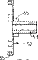
It is one single that cylinder 80 upper supports have, the clock spring shape sheet spring of screw winding, and its inner is fixed on the live axle 45, and its outer end is fixed on the housing 80.The inner of spring fixes on the axle by being adhesively fixed, thereby makes the spline on the axle form cooperatively interacting between spring steel and the axle.Drum housing 80 is made by plastic material, its inboard roughening, its main region is bonded at the adjacently situated surfaces of spring, its setting is such, axle 45 pins and can not rotate, the pulling rope ends rotates winding drum so that interact between the internal clickwork, rotate with respect to axle around its axis to drive winding ratchet, and outer ratchet rides on the outer ratchet.The rotation of winding ratchet 52 causes that spring cylinder 80 is by central gear 65, the rotational speed that spur gear 87 and ring gear 88 reduce greatly with the rotating speed with respect to winding drum 69.When rope is pulled to its range, damping spring is tensioned, discharging rope like this can allow damping spring 76 to change winding drum turning to respect to winding ratchet 52, winding ratchet 52 is locked by the cooperatively interacting of ratchet step on ratchet 63 and the ratchet extension 89, can not reverse, thereby allow on main spring 90, to apply additional tension to store as potential energy.Spur rope on the winding drum and release subsequently continuously, can cause the stack of the potential energy stored in the spring 90, until reaching the optimum tension value.
The front portion of cam member, axle 45 is supporting small gear 1 04, and it comprises the suitable nipper portion 105 that matches with the tooth of the starter ring for the treatment of cranking internal combustion engine, intermediate portion 106, and the suitable back ratchet 107 that matches with ratchet 100.Small gear 104 utilizes pressure spring 108 to be subjected to backward elastic force with respect to gear housing 35.Intermediate portion has a plurality of helical splines or tooth 110 on the surface 109 within it; Its helical spline or tooth 48 suitable and on the live axle cooperate.Setting should be such, makes relatively rotating between axle 45 and the small gear 104 can cause small gear along the axis of axle 45 or move to the limit of its stroke forward or backward.
When small gear when live axle moves axially, it slides along ratchet 100, the different profile of ratchet matches with ratchet 107 on small gear.The protuberance terminal end shape of ratchet 100 is provided with like this, make the corresponding recesses of protuberance by ratchet of ratchet be subjected to " from moving cam " control (selfcaming), and be provided with like this, make as shown in Figure 2, whole forward the time when small gear, only need very little power that ratchet is cooperated with the small gear disengaging.
In operation, pulling coiling rope can make winding drum 69 rotate, thereby makes the corresponding rotation of whole drive unit that comprises live axle 45.Effect by spring 108 makes small gear be subjected to fixing slightly and can not rotate, thereby makes small gear be forwarded to a position, and the respective teeth on the starter ring of this position gear 105 and internal-combustion engine to be started cooperates.When small gear walked to the terminal of its stroke, the shape of the ratchet shown in Figure 12 C can match with the groove of ratchet 107, thereby the locking small gear can not rotate with respect to small gear housing and coupled housing 10.Simultaneously, owing to the front end of small gear at its stroke, axle 45 also can lock and not rotate.The pulling rope can make spring 90 wind spring 90 and make cam rotation in the above described manner.The continuous pulling of coiling rope can make spring 90 tighten gradually, rotates to cam lobe 97 until cam 94 and cooperates with ratchet 100, thereby promote pawl body 100, it is broken away from the corresponding recesses of the ratchet 107 of small gear 104 cooperate.
Except that spring, the element of starting arrangement is made by the structural plasticity material entirely.Thereby make final starting arrangement light weight, do not need bearing, anticorrosion substantially except that spring.
The cam releasing structure of said apparatus can prevent the spring overwind.If the spring overwind just no longer can be realized the level and smooth transmission of spring energy, under many circumstances, spring wraps tightly (collapses) to prevent a large amount of or enough energy transfer, and cam releasing device of the present invention has overcome the problems referred to above.Just can change the output performance of spring by the gear ratio between the various elements that change epicyclic train, just can change the energy transfer arrangement of spring self by the combination of change elastic length, thickness and width.
The aforesaid starting arrangement of cardinal principle according to the present invention is suitable for starting various internal-combustion engines.
Claims (25)
1. mechanical priming device, comprise the clockwork spring (90) that is used for storing energy, on above-mentioned spring, apply energy Conversion of energy drive unit (45,48) with above-mentioned storage so that winding device of storing energy (69) and spring discharge therein so that starting pulse to be provided to internal-combustion engine, it is characterized in that: described spring and winding device and control gear (94,95,100,107) synergy, described control gear automatically discharge the energy of storing in the spring to live axle be suitable for storing certain energy in spring after.
2. device as claimed in claim 1 is characterized in that: described control gear is included in the braking device (100) that stops drive shaft turns in the winding process, and releasing device (94) is used for unclamping live axle after winding process finishes.
3. device as claimed in claim 2 is characterized in that: described braking device comprises ratchet (100) and the corresponding ratchet (107) that acts between live axle and the device case.
4. device as claimed in claim 3 is characterized in that: described ratchet (100) is positioned on the standing part of housing (10), and ratchet links to each other with live axle (45).
5. as claim 3 or 4 described devices, it is characterized in that: described ratchet (100) interacts with cam face (94), cam face responds winding operation and rotates, setting should be such, and the rotation of cam cooperates with the ratchet disengaging after making cam surface edges that predetermined energy be arranged in spring.
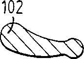
6. device as claimed in claim 5 is characterized in that: cam is driven by winding device (69) by spring housing (80).
7. device as claimed in claim 6 is characterized in that: cam is driven by a planet gear train (26,95) by above-mentioned spring housing.
8. as the described device of each claim in the claim 3 to 7, wherein ratchet is included in the wheel (107) that its outer surface has the ratchet recesses of certain profile, each groove is suitable for matching with the protuberance of respective profile on ratchet (100) end, setting is such, makes the desired friction that makes ratchet break away from cooperation from corresponding ratchet recesses reach minimum.
9. as the described device of one of claim 3 to 8, it is characterized in that: ratchet forms the part of driving pinion (106,105), and it matches with the starter ring of internal-combustion engine to be started.
10. device as claimed in claim 9 is characterized in that: driving pinion and ratchet have center hole, cut out multiple thread or tooth in the inside of center hole.
11. device as claimed in claim 10 is characterized in that: described driving pinion (105,106) is suitable for being installed on the corresponding multi-part tooth that is supported on the live axle front end, and is suitable for placing near the starter ring of internal-combustion engine to be started.
12. device as claimed in claim 11, it is characterized in that: small gear for example utilizes that pressure spring (108) makes it be partial to a position, cooperate to break away from above-mentioned starter ring, setting is such, for small gear is cooperated with the starter ring, small gear is advanced to cooperate with starter ring itself along multiple thread or spiral shell tooth with respect to the rotation of the live axle of driving pinion.
13. device as claimed in claim 12 is characterized in that: ratchet (100) extends along the small gear direct of travel, cooperates to keep with corresponding recesses on the ratchet.
14. device as claimed in claim 12, it is characterized in that: when beginning to reel, small gear (105,106) stops its rotation by ratchet (100), and axle (45) freely rotates, and the interaction of bull tooth or screw thread is used to make small gear to be meshed with the starter ring.
15. each described starting arrangement in the claim as described above, it is characterized in that: described spring assembly comprises a plurality of clockwork springs.
16. each described starting arrangement in the claim as described above, it is characterized in that: described winding device comprises a cable traction coiler (74).
17. each described starting arrangement in the claim as described above is characterized in that: the inner of spiral is fixed on axle and goes up (45), and rotate to tighten spring the outer end of spring spiral.
18. each described starting arrangement in the claim as described above, it is characterized in that: described drive unit comprises that is suitable for a small gear that matches with profile of tooth ring on the internal combustion engine flywheel to be started, it is characterized in that before spring assembly is reeled small gear matches with starter ring on the machine.
19. each described device in the claim as described above is characterized in that: described winding device comprises the concentric ratchet between rope cylinder (69) and the ring gear of acting on winding ratchet (52) assembly.
20. each described device in the claim as described above, it is characterized in that: the gear train between winding device and cylinder is planetary pinion train (65,87,88).
21. each described device in the claim as described above, it is characterized in that: the element except that spring is made by plastic material.
22. each described device in the claim as described above is characterized in that: by use between spring and the axle binder realize spring spiral (90) inner with spool (45) between be connected.
23. each described device in the claim is characterized in that: utilize binder to realize the upper end of spring spiral (90) and being connected of spring housing (80) as described above.
24. as claim 22 or 23 described devices, it is characterized in that: described binder is that methyl methacrylate is the binder of base.
25. an internal-combustion engine comprises the described mechanical priming device of aforementioned any one claim.
Applications Claiming Priority (2)
| Application Number | Priority Date | Filing Date | Title |
|---|---|---|---|
| GBGB9503488.0A GB9503488D0 (en) | 1995-02-22 | 1995-02-22 | Pentham starter |
| GB9503488.0 | 1995-02-22 |
Publications (2)
| Publication Number | Publication Date |
|---|---|
| CN1181127A CN1181127A (en) | 1998-05-06 |
| CN1077225C true CN1077225C (en) | 2002-01-02 |
Family
ID=10770036
Family Applications (1)
| Application Number | Title | Priority Date | Filing Date |
|---|---|---|---|
| CN96193224A Expired - Fee Related CN1077225C (en) | 1995-02-22 | 1996-02-16 | Mechanical starter motor |
Country Status (12)
| Country | Link |
|---|---|
| US (1) | US5970940A (en) |
| EP (1) | EP0811120B1 (en) |
| JP (1) | JPH11500207A (en) |
| KR (1) | KR100472740B1 (en) |
| CN (1) | CN1077225C (en) |
| AT (1) | ATE172518T1 (en) |
| AU (1) | AU4673196A (en) |
| BR (1) | BR9607417A (en) |
| DE (1) | DE69600840T2 (en) |
| GB (2) | GB9503488D0 (en) |
| WO (1) | WO1996026363A1 (en) |
| ZA (1) | ZA961416B (en) |
Families Citing this family (13)
| Publication number | Priority date | Publication date | Assignee | Title |
|---|---|---|---|---|
| GB9822283D0 (en) * | 1998-10-14 | 1998-12-09 | Hart William B | Mechanical starting aid for internal combustion engines fitted with recoil starters |
| US6230678B1 (en) | 1998-10-30 | 2001-05-15 | Briggs & Stratton Corporation | Starting and stopping device for internal combustion engine |
| US6647942B2 (en) | 1998-10-30 | 2003-11-18 | Briggs & Stratton Corporation | Engine starting and stopping device |
| US6615787B2 (en) | 1998-10-30 | 2003-09-09 | Briggs & Stratton Corporation | Engine starting and stopping device |
| US6595176B2 (en) | 1998-10-30 | 2003-07-22 | Briggs & Stratton Corporation | Engine starting and stopping device |
| US6622683B2 (en) | 1998-10-30 | 2003-09-23 | Briggs & Stratton Corporation | Engine starting and stopping device |
| CA2441622C (en) * | 2001-03-16 | 2010-06-08 | Altech Generating Systems Llc | Alternator and method of manufacture |
| JP2003148305A (en) | 2001-11-16 | 2003-05-21 | Starting Ind Co Ltd | Recoil starter |
| US6782863B2 (en) | 2002-10-08 | 2004-08-31 | Mtd Products Inc. | Spring release starter |
| JP4346922B2 (en) * | 2002-10-21 | 2009-10-21 | スターテング工業株式会社 | Recoil starter |
| US7252065B1 (en) | 2006-05-11 | 2007-08-07 | Husqvarna Outdoor Products Inc. | Energy storing starting device |
| DE102013011978B3 (en) * | 2013-07-18 | 2014-11-06 | Andreas Reichart | Starter unit for a mobile device with an internal combustion engine |
| CN104358647A (en) * | 2014-11-07 | 2015-02-18 | 广西玉柴机器股份有限公司 | Mechanical starter |
Citations (1)
| Publication number | Priority date | Publication date | Assignee | Title |
|---|---|---|---|---|
| US3127883A (en) * | 1960-06-09 | 1964-04-07 | Perkins F Ltd | Spring starter motor |
Family Cites Families (11)
| Publication number | Priority date | Publication date | Assignee | Title |
|---|---|---|---|---|
| US2875851A (en) * | 1959-03-03 | Vakos | ||
| GB974737A (en) * | ||||
| US1511082A (en) * | 1920-07-19 | 1924-10-07 | Johnston Floyd | Self-starter |
| DE1212355B (en) * | 1960-06-03 | 1966-03-10 | Hirth Motoren K G | Turning device for internal combustion engines |
| US3692010A (en) * | 1970-11-27 | 1972-09-19 | Mcculloch Corp | Automatic system for spring starting an internal combustion engine |
| US3853109A (en) * | 1973-04-24 | 1974-12-10 | Mcculloch Corp | Method and apparatus starting an internal combustion engine |
| GB1579237A (en) * | 1976-03-24 | 1980-11-19 | Honda Motor Co Ltd | Engine starting device |
| US4104927A (en) * | 1976-11-29 | 1978-08-08 | Jensen Jorn Benned | Engine starter |
| US5083534A (en) * | 1989-04-05 | 1992-01-28 | Mitsubishi Jukogyo Kabushiki Kaisha | Spiral spring type starter apparatus for an internal combustion engine |
| GB2273961B (en) * | 1992-12-30 | 1995-11-29 | Gupta Sangram Sen | Engine starting mechanism |
| JPH07174061A (en) * | 1993-05-07 | 1995-07-11 | Nitsukari:Kk | Force storage type recoil starter |
-
1995
- 1995-02-22 GB GBGB9503488.0A patent/GB9503488D0/en active Pending
-
1996
- 1996-02-16 BR BR9607417A patent/BR9607417A/en not_active IP Right Cessation
- 1996-02-16 WO PCT/GB1996/000354 patent/WO1996026363A1/en active IP Right Grant
- 1996-02-16 JP JP8525478A patent/JPH11500207A/en not_active Ceased
- 1996-02-16 GB GB9603307A patent/GB2298242A/en not_active Withdrawn
- 1996-02-16 DE DE69600840T patent/DE69600840T2/en not_active Expired - Fee Related
- 1996-02-16 AT AT96902393T patent/ATE172518T1/en not_active IP Right Cessation
- 1996-02-16 EP EP96902393A patent/EP0811120B1/en not_active Expired - Lifetime
- 1996-02-16 US US08/894,531 patent/US5970940A/en not_active Expired - Fee Related
- 1996-02-16 KR KR1019970705791A patent/KR100472740B1/en not_active IP Right Cessation
- 1996-02-16 AU AU46731/96A patent/AU4673196A/en not_active Abandoned
- 1996-02-16 CN CN96193224A patent/CN1077225C/en not_active Expired - Fee Related
- 1996-02-22 ZA ZA961416A patent/ZA961416B/en unknown
Patent Citations (1)
| Publication number | Priority date | Publication date | Assignee | Title |
|---|---|---|---|---|
| US3127883A (en) * | 1960-06-09 | 1964-04-07 | Perkins F Ltd | Spring starter motor |
Also Published As
| Publication number | Publication date |
|---|---|
| BR9607417A (en) | 1998-06-23 |
| GB9503488D0 (en) | 1995-04-12 |
| WO1996026363A1 (en) | 1996-08-29 |
| AU4673196A (en) | 1996-09-11 |
| CN1181127A (en) | 1998-05-06 |
| KR19980702392A (en) | 1998-07-15 |
| DE69600840D1 (en) | 1998-11-26 |
| JPH11500207A (en) | 1999-01-06 |
| DE69600840T2 (en) | 1999-06-02 |
| EP0811120A1 (en) | 1997-12-10 |
| ZA961416B (en) | 1996-07-29 |
| GB2298242A (en) | 1996-08-28 |
| ATE172518T1 (en) | 1998-11-15 |
| MX9706340A (en) | 1997-11-29 |
| KR100472740B1 (en) | 2005-06-16 |
| US5970940A (en) | 1999-10-26 |
| GB9603307D0 (en) | 1996-04-17 |
| EP0811120B1 (en) | 1998-10-21 |
Similar Documents
| Publication | Publication Date | Title |
|---|---|---|
| CN1077225C (en) | Mechanical starter motor | |
| CN1734083A (en) | Engine starter | |
| US6834633B2 (en) | Spring release starter for chain saw | |
| EP1702781A2 (en) | Drive unit for hybrid vehicle | |
| CN1477305A (en) | Guy line wrap-around starting machine | |
| JPH07174061A (en) | Force storage type recoil starter | |
| US4640452A (en) | Device for driving nails or similar fastening elements | |
| CN101044314A (en) | Starter motor with idle gear | |
| EP1900936B1 (en) | Starter of small engine | |
| CN1763363A (en) | Recoil starter | |
| KR20130129128A (en) | Belt tightening drive | |
| US9797359B2 (en) | Starting device for an internal combustion engine | |
| CN1673518A (en) | Model engine starter | |
| CN209604183U (en) | A kind of chain saw with the double starting systems of flashlight | |
| JPH0616964Y2 (en) | Recoil starter | |
| CN1500681A (en) | Belt buckle pretensioner | |
| CN1721668A (en) | Power transmission unit | |
| US20080190701A1 (en) | Spring powered engine | |
| CN200971836Y (en) | Energy storage generator | |
| RU2085795C1 (en) | Mechanical energy accumulator | |
| CN102442258A (en) | Self-rescue capstan for trapped motor vehicle | |
| MXPA97006340A (en) | Start motor mecan | |
| CN220748437U (en) | Starter for miniature agricultural machinery | |
| CN102649531A (en) | Integrated type rear-mounted guide wheel rope discharge and rope storage friction winch | |
| CN109611252A (en) | A kind of chain saw with the double starting systems of flashlight |
Legal Events
| Date | Code | Title | Description |
|---|---|---|---|
| C06 | Publication | ||
| PB01 | Publication | ||
| C10 | Entry into substantive examination | ||
| SE01 | Entry into force of request for substantive examination | ||
| C14 | Grant of patent or utility model | ||
| GR01 | Patent grant | ||
| C19 | Lapse of patent right due to non-payment of the annual fee | ||
| CF01 | Termination of patent right due to non-payment of annual fee |