CN107708560B - Blood sampling device - Google Patents
Blood sampling device Download PDFInfo
- Publication number
- CN107708560B CN107708560B CN201680033834.XA CN201680033834A CN107708560B CN 107708560 B CN107708560 B CN 107708560B CN 201680033834 A CN201680033834 A CN 201680033834A CN 107708560 B CN107708560 B CN 107708560B
- Authority
- CN
- China
- Prior art keywords
- blood
- container
- puncture
- movable
- pressure
- Prior art date
- Legal status (The legal status is an assumption and is not a legal conclusion. Google has not performed a legal analysis and makes no representation as to the accuracy of the status listed.)
- Active
Links
Images


Classifications
-
- A—HUMAN NECESSITIES
- A61—MEDICAL OR VETERINARY SCIENCE; HYGIENE
- A61B—DIAGNOSIS; SURGERY; IDENTIFICATION
- A61B5/00—Measuring for diagnostic purposes; Identification of persons
- A61B5/02—Detecting, measuring or recording pulse, heart rate, blood pressure or blood flow; Combined pulse/heart-rate/blood pressure determination; Evaluating a cardiovascular condition not otherwise provided for, e.g. using combinations of techniques provided for in this group with electrocardiography or electroauscultation; Heart catheters for measuring blood pressure
- A61B5/021—Measuring pressure in heart or blood vessels
- A61B5/022—Measuring pressure in heart or blood vessels by applying pressure to close blood vessels, e.g. against the skin; Ophthalmodynamometers
-
- A—HUMAN NECESSITIES
- A61—MEDICAL OR VETERINARY SCIENCE; HYGIENE
- A61B—DIAGNOSIS; SURGERY; IDENTIFICATION
- A61B5/00—Measuring for diagnostic purposes; Identification of persons
- A61B5/02—Detecting, measuring or recording pulse, heart rate, blood pressure or blood flow; Combined pulse/heart-rate/blood pressure determination; Evaluating a cardiovascular condition not otherwise provided for, e.g. using combinations of techniques provided for in this group with electrocardiography or electroauscultation; Heart catheters for measuring blood pressure
-
- A—HUMAN NECESSITIES
- A61—MEDICAL OR VETERINARY SCIENCE; HYGIENE
- A61B—DIAGNOSIS; SURGERY; IDENTIFICATION
- A61B5/00—Measuring for diagnostic purposes; Identification of persons
- A61B5/15—Devices for taking samples of blood
-
- A—HUMAN NECESSITIES
- A61—MEDICAL OR VETERINARY SCIENCE; HYGIENE
- A61B—DIAGNOSIS; SURGERY; IDENTIFICATION
- A61B5/00—Measuring for diagnostic purposes; Identification of persons
- A61B5/15—Devices for taking samples of blood
- A61B5/150007—Details
- A61B5/150015—Source of blood
- A61B5/150022—Source of blood for capillary blood or interstitial fluid
-
- A—HUMAN NECESSITIES
- A61—MEDICAL OR VETERINARY SCIENCE; HYGIENE
- A61B—DIAGNOSIS; SURGERY; IDENTIFICATION
- A61B5/00—Measuring for diagnostic purposes; Identification of persons
- A61B5/15—Devices for taking samples of blood
- A61B5/150007—Details
- A61B5/150053—Details for enhanced collection of blood or interstitial fluid at the sample site, e.g. by applying compression, heat, vibration, ultrasound, suction or vacuum to tissue; for reduction of pain or discomfort; Skin piercing elements, e.g. blades, needles, lancets or canulas, with adjustable piercing speed
- A61B5/150061—Means for enhancing collection
- A61B5/150068—Means for enhancing collection by tissue compression, e.g. with specially designed surface of device contacting the skin area to be pierced
-
- A—HUMAN NECESSITIES
- A61—MEDICAL OR VETERINARY SCIENCE; HYGIENE
- A61B—DIAGNOSIS; SURGERY; IDENTIFICATION
- A61B5/00—Measuring for diagnostic purposes; Identification of persons
- A61B5/15—Devices for taking samples of blood
- A61B5/150007—Details
- A61B5/150053—Details for enhanced collection of blood or interstitial fluid at the sample site, e.g. by applying compression, heat, vibration, ultrasound, suction or vacuum to tissue; for reduction of pain or discomfort; Skin piercing elements, e.g. blades, needles, lancets or canulas, with adjustable piercing speed
- A61B5/150061—Means for enhancing collection
- A61B5/150099—Means for enhancing collection by negative pressure, other than vacuum extraction into a syringe by pulling on the piston rod or into pre-evacuated tubes
-
- A—HUMAN NECESSITIES
- A61—MEDICAL OR VETERINARY SCIENCE; HYGIENE
- A61B—DIAGNOSIS; SURGERY; IDENTIFICATION
- A61B5/00—Measuring for diagnostic purposes; Identification of persons
- A61B5/15—Devices for taking samples of blood
- A61B5/150007—Details
- A61B5/150053—Details for enhanced collection of blood or interstitial fluid at the sample site, e.g. by applying compression, heat, vibration, ultrasound, suction or vacuum to tissue; for reduction of pain or discomfort; Skin piercing elements, e.g. blades, needles, lancets or canulas, with adjustable piercing speed
- A61B5/150106—Means for reducing pain or discomfort applied before puncturing; desensitising the skin at the location where body is to be pierced
- A61B5/150114—Means for reducing pain or discomfort applied before puncturing; desensitising the skin at the location where body is to be pierced by tissue compression, e.g. with specially designed surface of device contacting the skin area to be pierced
-
- A—HUMAN NECESSITIES
- A61—MEDICAL OR VETERINARY SCIENCE; HYGIENE
- A61B—DIAGNOSIS; SURGERY; IDENTIFICATION
- A61B5/00—Measuring for diagnostic purposes; Identification of persons
- A61B5/15—Devices for taking samples of blood
- A61B5/150007—Details
- A61B5/150053—Details for enhanced collection of blood or interstitial fluid at the sample site, e.g. by applying compression, heat, vibration, ultrasound, suction or vacuum to tissue; for reduction of pain or discomfort; Skin piercing elements, e.g. blades, needles, lancets or canulas, with adjustable piercing speed
- A61B5/150106—Means for reducing pain or discomfort applied before puncturing; desensitising the skin at the location where body is to be pierced
- A61B5/150145—Means for reducing pain or discomfort applied before puncturing; desensitising the skin at the location where body is to be pierced by negative pressure, e.g. suction, vacuum
-
- A—HUMAN NECESSITIES
- A61—MEDICAL OR VETERINARY SCIENCE; HYGIENE
- A61B—DIAGNOSIS; SURGERY; IDENTIFICATION
- A61B5/00—Measuring for diagnostic purposes; Identification of persons
- A61B5/15—Devices for taking samples of blood
- A61B5/150007—Details
- A61B5/150053—Details for enhanced collection of blood or interstitial fluid at the sample site, e.g. by applying compression, heat, vibration, ultrasound, suction or vacuum to tissue; for reduction of pain or discomfort; Skin piercing elements, e.g. blades, needles, lancets or canulas, with adjustable piercing speed
- A61B5/150106—Means for reducing pain or discomfort applied before puncturing; desensitising the skin at the location where body is to be pierced
- A61B5/15016—Means for reducing pain or discomfort applied before puncturing; desensitising the skin at the location where body is to be pierced by accessories for bringing the piercing element into the body, e.g. through rotation of the piercing element
-
- A—HUMAN NECESSITIES
- A61—MEDICAL OR VETERINARY SCIENCE; HYGIENE
- A61B—DIAGNOSIS; SURGERY; IDENTIFICATION
- A61B5/00—Measuring for diagnostic purposes; Identification of persons
- A61B5/15—Devices for taking samples of blood
- A61B5/150007—Details
- A61B5/150343—Collection vessels for collecting blood samples from the skin surface, e.g. test tubes, cuvettes
-
- A—HUMAN NECESSITIES
- A61—MEDICAL OR VETERINARY SCIENCE; HYGIENE
- A61B—DIAGNOSIS; SURGERY; IDENTIFICATION
- A61B5/00—Measuring for diagnostic purposes; Identification of persons
- A61B5/15—Devices for taking samples of blood
- A61B5/150007—Details
- A61B5/150351—Caps, stoppers or lids for sealing or closing a blood collection vessel or container, e.g. a test-tube or syringe barrel
-
- A—HUMAN NECESSITIES
- A61—MEDICAL OR VETERINARY SCIENCE; HYGIENE
- A61B—DIAGNOSIS; SURGERY; IDENTIFICATION
- A61B5/00—Measuring for diagnostic purposes; Identification of persons
- A61B5/15—Devices for taking samples of blood
- A61B5/150007—Details
- A61B5/150374—Details of piercing elements or protective means for preventing accidental injuries by such piercing elements
- A61B5/150381—Design of piercing elements
- A61B5/150412—Pointed piercing elements, e.g. needles, lancets for piercing the skin
-
- A—HUMAN NECESSITIES
- A61—MEDICAL OR VETERINARY SCIENCE; HYGIENE
- A61B—DIAGNOSIS; SURGERY; IDENTIFICATION
- A61B5/00—Measuring for diagnostic purposes; Identification of persons
- A61B5/15—Devices for taking samples of blood
- A61B5/150007—Details
- A61B5/150748—Having means for aiding positioning of the piercing device at a location where the body is to be pierced
-
- A—HUMAN NECESSITIES
- A61—MEDICAL OR VETERINARY SCIENCE; HYGIENE
- A61B—DIAGNOSIS; SURGERY; IDENTIFICATION
- A61B5/00—Measuring for diagnostic purposes; Identification of persons
- A61B5/15—Devices for taking samples of blood
- A61B5/151—Devices specially adapted for taking samples of capillary blood, e.g. by lancets, needles or blades
- A61B5/15186—Devices loaded with a single lancet, i.e. a single lancet with or without a casing is loaded into a reusable drive device and then discarded after use; drive devices reloadable for multiple use
- A61B5/15188—Constructional features of reusable driving devices
- A61B5/15192—Constructional features of reusable driving devices comprising driving means, e.g. a spring, for retracting the lancet unit into the driving device housing
- A61B5/15194—Constructional features of reusable driving devices comprising driving means, e.g. a spring, for retracting the lancet unit into the driving device housing fully automatically retracted, i.e. the retraction does not require a deliberate action by the user, e.g. by terminating the contact with the patient's skin
-
- A—HUMAN NECESSITIES
- A61—MEDICAL OR VETERINARY SCIENCE; HYGIENE
- A61B—DIAGNOSIS; SURGERY; IDENTIFICATION
- A61B5/00—Measuring for diagnostic purposes; Identification of persons
- A61B5/15—Devices for taking samples of blood
- A61B5/150007—Details
- A61B5/150374—Details of piercing elements or protective means for preventing accidental injuries by such piercing elements
- A61B5/150381—Design of piercing elements
- A61B5/150412—Pointed piercing elements, e.g. needles, lancets for piercing the skin
- A61B5/150435—Specific design of proximal end
-
- A—HUMAN NECESSITIES
- A61—MEDICAL OR VETERINARY SCIENCE; HYGIENE
- A61B—DIAGNOSIS; SURGERY; IDENTIFICATION
- A61B5/00—Measuring for diagnostic purposes; Identification of persons
- A61B5/15—Devices for taking samples of blood
- A61B5/153—Devices specially adapted for taking samples of venous or arterial blood, e.g. with syringes
- A61B5/154—Devices using pre-evacuated means
Abstract
The invention aims to provide a blood sampling device, which can collect blood in a short time after puncture without blood splashing to the outside of a container for collecting blood. Also provided is a blood collection device which can collect blood in a short time after puncturing without scattering the blood to the outside of a container for collecting blood. In order to achieve the above object, one of the blood sampling devices of the present invention is typically provided with: a container part provided with a threaded part, wherein the container part is a system with one closed end; a holder holding the container; and a piercing portion mountable on the container or holder; a through hole of the puncture part; a puncture part protection member for protecting the puncture part and the container part.
Description
Technical Field
The present invention relates to blood collection devices.
Background
Patent document 1 (jp-a 7-213925) describes a micro-volume-constant blood collection titrating device capable of titrating a certain amount of blood in a predetermined test device. Further, patent document 2 (japanese patent application laid-open No. 2002-219115) describes a blood collection device that can secure a blood volume required for analyzing a specific component of a body fluid in a short time, and that can perform a blood collection operation without causing a blood collection failure and pain.
Documents of the prior art
Patent document
Patent document 1: japanese laid-open patent publication No. 7-213925
Patent document 2: japanese patent laid-open publication No. 2002-
Disclosure of Invention
Problems to be solved by the invention
In the blood collection device described in patent document 1, the puncture blood collection tip is made of a plastic that is not easily deformed, and therefore, it is difficult to suck blood into the blood holding portion (blood suction channel). Therefore, there are the following problems: it is difficult to collect blood in an amount required for examination (several tens to several hundreds microliters), and several punctures are required, which causes a burden on the patient. In addition, since the blood suction channel is open to the atmosphere, there is a risk that blood adheres to surrounding structures or blood splashes into the outside air, causing infection by a third person.
The blood collecting instrument described in patent document 2 has the following problems: since the blood sampling site is pressurized after the puncture, the flow of blood flow is compressed, and it takes time until a desired amount of blood is collected without flowing out of the blood sampling site or even if bleeding occurs. When blood collection takes time, the concentration of components in dry blood at the puncture site varies, resulting in deterioration of the examination accuracy. In addition, when pressurization is performed after puncturing, there is a problem that the punctured site is dried during pressurization, and a sufficient amount of blood cannot be collected.
The invention aims to provide a blood sampling device, which can collect blood in a short time after puncture without blood splashing to the outside of a container for collecting blood.
Means for solving the problems
In order to solve the above problems, a typical blood collection device according to the present invention includes: a container having an opening and a closing part at both ends; a holder for holding the container with the opening of the container facing upward; a fixing portion for fixing the blood collection object in a state of facing the opening portion; a pressure changing unit that pressurizes the blood collection target or makes a space surrounded by the blood collection target and the container negative in pressure; a puncture unit which is mounted on the container so as to be relatively movable and punctures the blood collection subject after the pressure is varied by the pressure varying unit; and a cap for closing an opening of the container in which the blood is stored.
Effects of the invention
According to the present invention, it is possible to provide a blood sampling device capable of sampling blood in a short time after puncturing without causing blood to splash out of a container for sampling blood.
Problems, structures, and effects other than those described above will be made more apparent by the following description of the embodiments.
Drawings
Fig. 1A brings a finger into contact with the blood collecting device and the fixing portion of the first embodiment.
Fig. 1B shows a perspective view of the blood collection device of the first embodiment.
FIG. 1C is a sectional view of the finger upper surface fixing part of the blood collecting device according to the first embodiment.
Fig. 1D shows a sectional view of a finger lower surface side fixing member of the blood collecting device of the first embodiment.
Fig. 1E shows a sectional view of a fixing portion of the blood collecting device of the first embodiment.
Fig. 2 shows a process of the blood collecting device of the first embodiment.
Fig. 3A shows a puncturing process of the blood collecting device of the first embodiment.
Fig. 3B is a perspective view showing a puncturing process of the blood collecting device of the first embodiment.
Fig. 4A shows the first embodiment of the lancing device with the needle protruding during lancing.
Fig. 4B is a perspective view showing the needle protrusion in the puncturing process of the blood collecting device according to the first embodiment.
Fig. 5 shows the blood collection device of the first embodiment after puncturing.
Fig. 6A shows a blood collection process of the blood collection device of the first embodiment.
Fig. 6B is a perspective view showing a blood collecting process of the blood collecting device of the first embodiment.
Fig. 7A shows a process of protecting the puncture site of the first embodiment.
Fig. 7B is a perspective view showing a process of protecting the puncture site according to the first embodiment.
Fig. 8A is a perspective view of a blood collection device of a second embodiment.
Fig. 8B is a top view of the lancing device of the second embodiment.
FIG. 8C is a cross-sectional view of the holder and negative pressure device of the lancing device of the second embodiment.
Fig. 8D shows a cross section of a lancing device according to a second embodiment.
Fig. 9 shows a cross section of a lancing device according to a second embodiment.
Fig. 10 shows a process of the blood collecting device of the second embodiment.
Fig. 11A shows a puncturing process of the blood sampling device of the second embodiment.
FIG. 11B illustrates the needle protruding during lancing of the second embodiment of the lancing device.
Fig. 11C shows the blood collection device of the second embodiment after puncturing.
Fig. 12A shows a blood collection process of the blood collection device of the second embodiment.
Fig. 12B shows the container portion after blood collection of the blood collection device according to the second embodiment.
Fig. 13A is a perspective view of a blood collection device of a third embodiment.
Fig. 13B is a perspective view of a puncturing part of the blood sampling device according to the third embodiment.
Fig. 13C is a perspective view of a container portion of the blood sampling device of the third embodiment.
Fig. 13D is a perspective view of the container portion and the puncturing portion of the blood sampling device according to the third embodiment.
Fig. 13E is a top view of a third embodiment of a lancing device.
FIG. 13F shows a cross section of a blood drawing device of a third embodiment.
Fig. 14 shows a process of the blood collecting device of the third embodiment.
Fig. 15A shows a puncturing process of the blood sampling device of the third embodiment.
Fig. 15B shows a puncturing process of the blood sampling device of the third embodiment.
Fig. 15C shows a blood collection process of the blood collection device of the third embodiment.
Detailed Description
Hereinafter, embodiments of the present invention will be described with reference to the drawings.
Example 1
Fig. 1A and 1B show a structure of a blood collection device according to a first embodiment. Fig. 1A is a sectional view and fig. 1B is a perspective view.
The blood collection device of the present invention includes a fixing portion 2 for fixing a finger 4 above a blood collection device 1 in which a movable container portion 110, a movable puncture portion 120, a drive fixing portion 130, and a drive portion 140 are integrally combined.
The movable container part 110 includes a container 112 for storing blood collected from the finger 4. The volume of blood that can be stored in the container 112 varies depending on the application, and according to the embodiment of the present embodiment, a large volume (about several tens to several hundreds microliters) of blood can be collected at most. The container 112 is provided with a movable lid 113 at an opening for receiving blood, and is configured to be openable and closable. The container 112 itself is also configured to be manually movable in the horizontal direction with respect to the movable container part 110. The range of movement of the container 112 is limited by the guide mechanism 113 and the positioning mechanism 1014. The fixed portion 2 and the movable puncture portion 120 are provided with a groove engageable with a projection 208 provided on the fixed portion 2 and a projection 111 projecting from the movable puncture portion 120.
The movable puncture part 120 is connected to the movable container part 110, and includes a needle tip 122, a needle part connecting part 123, and a needle holding part 124 therein. The needle tip 122 is initially fixed to the needle holding portion 124, but is connected to a drive fixing portion described later, and is fitted to the tip of a shaft 125 provided in the drive fixing portion, thereby being detached from the needle holding portion 124. Therefore, it is preferable to connect the needle portion 123 and the needle holding portion 124 to a detachable degree by a slight force. The needle tip 122 and the shaft 125 are detachably connected by the needle portion connecting portion 123, and the needle tip 122 and the shaft 125 are separable when the blood collection procedure is completed. When the needle connecting portion 123 is connected to the detachable shaft 125, the needle connecting portion 123 is detached from the needle holding portion 124, and the movable puncturing part 120 is connected to the drive fixing portion 130.
The drive fixing unit 130 is connected to the movable puncture unit 120, and includes a spring housing 131 and a pressure source 132 for applying pressure to the inside of the spring housing 131, wherein the spring housing 131 has a needle connected to a spring. The pressure source 132 is a negative pressure source for generating negative pressure in the present embodiment. Further, a shaft 125 detachable from the needle tip 122 and four springs having one end fixed to a rib of the shaft and the other end fixed to the drive fixing portion 130 are provided in the spring housing portion 131. In addition, a slidable puncture fixing portion 133 is provided to fix the position of the needle portion by contacting the rib of the shaft.
The driving unit 140 is connected to a fixing unit 2 described later, and includes a sphygmomanometer 141 and a pressurizing device 142. The pressurizing device 142 sends air to a pressed object 203 around a finger described later, and the sphygmomanometer 141 acquires pressure information from a pressure gauge 207 provided in the pressed object 203. Further, a drive switch 143 for controlling the driving of the pressurizing device 142 is provided.
The fixing portion 2 is formed by: a finger upper surface fixing part 201, a finger lower surface fixing part 202, a finger fixing support 205, a pressing object 203 of a pneumatic type arranged around the finger body, and a movable lower surface support 206. The finger upper surface side fixing member 201 and the finger lower surface side fixing member 202 are preferably made of a resin material or an elastic material because they need to be in contact with the finger 4 to maintain a certain degree of airtightness. The pressing piece 203 provided around the finger body is expanded so that the puncture site of the finger 4 is sealed by the finger upper surface side fixing member 201, the finger lower surface side fixing member 202, and the pressing piece 203. Preferably, the fixed unit 2 is provided with a blood pressure sensor 207 for measuring a blood pressure value when the finger is pressed by the pressing object 203 and communicating the blood pressure value to the sphygmomanometer 141 of the driving unit 140 via the connecting body 3 such as a wire. And the pressers 203 are connected with the pressurizing means 142 of the driving part 140.
As shown in fig. 1C, the finger top surface fixing member 201 includes a fixing portion 2011 and an elastic member 2012, and the elastic member 2012 is tightly attached to the finger. Fig. 1D also shows a finger lower surface side fixing member 202, which has the same structure as the finger upper surface side fixing member 201. Fig. 1E shows a state in which the finger upper surface fixing member 201 and the finger lower surface side fixing member 202 are combined. By closely attaching the elastic member 2012 so as to cover the entire circumference of the finger, the finger is prevented from being displaced during blood collection, and the puncture portion 209 through which blood is actually collected is sealed. Even if the sealing is not complete, the pressure in puncture portion 209 may be maintained at a pressure at least lower than the pressure of blood pressure at least during blood collection. In addition, the fixing portion 2 may be provided to cover the entire finger.
In the blood collection device, the movable container portion 110 and the movable puncture portion 120 may come into contact with blood, and therefore, are replaced and used every time blood collection is performed. On the other hand, since the fixing unit 2, the driving fixing unit 130, and the driving unit 140 have a small risk of coming into contact with blood, they do not need to be replaced and used every time of measurement, and can be reused. Therefore, it is preferable that the fixed unit 2, the movable container unit 110, the movable puncturing unit 120, and the driving fixed unit 130 are all detachably assembled. The fixed portion 2 and the movable container portion 110 can be connected by engaging the protrusion 208 of the fixed portion 2 with the movable container portion 110. Similarly, the movable container 110 and the movable puncturing part 120 are connected by the protrusion 111 of the movable container 110, and the movable puncturing part 120 and the drive fixing part 130 are connected by the protrusion 121 of the movable puncturing part 120. When the operator connects the movable puncture part 120 and the fixed drive part 130, the operator positions the rib of the shaft by the puncture part fixing part 133 of the fixed drive part 130, and in this state, the needle connecting part 123 is attached to the tip of the shaft.
The process of blood collection using the blood collection device of the first embodiment will be described with reference to fig. 2 to 7.
First, the drive switch 143 of the drive unit 140 is pressed with the finger 4 inserted into the insertion hole provided in the fixed unit 2 (step 301). The pressing device 142 is then operated, and the pressing object 203 around the finger fastens the finger 4 (step 302). Then, the blood pressure of the finger 4 is monitored based on the output of the pressure sensor 207 when the compression object 203 around the finger fastens the finger 4, and the blood pressure is transmitted to the sphygmomanometer 141 of the driving unit 140. After the blood pressure meter 141 measures the highest blood pressure, the pressure in the compression object 203 around the finger is reduced by the pressurizing device 142, and the lowest blood pressure is measured. The calculation method of the highest blood pressure and the lowest blood pressure may be the same as that of the conventional sphygmomanometer (step 303).
Thereafter, the pressure in the compressed object around the finger is increased by the pressure increasing device so as to be equal to or lower than the highest blood pressure and equal to or higher than the lowest blood pressure (step 304). By setting the blood pressure to be lower than the highest blood pressure and higher than the lowest blood pressure, blood flow stagnation due to excessive tightening is prevented, and bleeding during puncturing can be promoted by applying an appropriate pressure.
When the pressure in the compressed matter around the finger reaches a pressure value within the appropriate range, the lancet moves and pulls out the container 112 of the movable container part 110 (step 305). Fig. 3A and 3B show the state of the blood collection device in this state. A guide mechanism 1013 formed of a guide rail is provided on a side surface of the container 112, and the container 112 can be pulled out along the guide rail. The maximum amount of movement that can be pulled out is also controlled by the positioning mechanism 1014.
The puncture 102 and the spring housing 131 become a space connected by the movement of the container 112. When the negative pressure device 1032 is driven in this state, the spring housing 1031 and the inside of the puncture hole 102 become negative pressure, and blood is likely to flow out to the outside of the finger 4 by the differential pressure at the time of puncture (step 306). Further, the negative pressure device 132 is driven by pressing the drive switch 143.
When puncture hole 209 becomes negative pressure, movable puncture unit 120 is moved. The movable puncture part 120 separates the puncture fixing part 133 from the positioning 134 of the puncture fixing part, and manually pulls the puncture fixing part 133. Then, as shown in fig. 4, the springs 112 to 115 to which the needle tip 122 is fixed expand and contract, and the needle portion is extended with respect to the finger to puncture the finger 4 (step 307). After penetrating the finger, all springs return to their natural length as shown in fig. 5, and the needle tip 122 is removed from the penetration site.
Thereafter, as shown in fig. 6, the container 112 is moved to be disposed just below the puncture site, and the oozing blood 301 is stored in the container 112 (step 308). The container 112 is preferably made of a transparent resin, and is configured such that the blood collection state of the blood 301 can be visually observed from the outside. In addition, it is preferable to provide a scale for confirming whether or not a sufficient amount is collected, depending on the purpose.
After the predetermined amount of blood collected in the container portion is confirmed (step 309), the pressure in the compressed object around the finger is reduced by the pressurizing device. By reducing the pressure of the compressed matter around the finger, blood flows again from the vein of the compressed finger, and it is necessary to block the wound of the finger at the puncture site to prevent unnecessary bleeding (step 310).
Thereafter, the lid 113 of the container portion is moved to close the opening of the container. In order to protect the finger puncture section, the lower surface holder 206 is moved to a position below the finger puncture section to protect the finger puncture section (step 311, fig. 7A). Thereafter, the movable container portion 101 is detached from the fixed portion 2 and the movable puncture portion 103 (step 312). Since the opening of the container 112 is closed by the lid 113 at the time of removal, the collected blood can be prevented from scattering to the surroundings. The collected blood can be sent to an analyzer capable of quantitatively and qualitatively analyzing the components of the blood for each movable container part 110.
In the first embodiment, by providing the pressing member 203 and the negative pressure source 132, even with a large volume of blood collection, blood collection can be performed without taking time and without repeating the puncture process a plurality of times.
Further, as another effect of the present invention, since the movable lid is provided in the container for storing the collected blood, it is possible to reduce the risk that the blood overflows to contaminate the surroundings or bacteria floating in the air are mixed in the collected blood when the collected blood is transported or stored.
Further, as another effect of the present invention, since the pressing object 203 applies a pressing pressure in an appropriate range to the finger before the puncture process, when the pressing of the pressing object 203 is released, blood is less likely to leak from the puncture portion (wound), and the risk of contamination of the surroundings by bleeding from the wound after the blood collection process can be reduced.
In addition, as another effect of the present invention, since the reusable mechanism and the mechanism to be replaced after a blood collection process can be separated and combined, the cost required for the blood collection process can be reduced.
Example 2
Next, a second embodiment of the present invention will be described with reference to fig. 8 to 12. The second embodiment is different from the first embodiment in that an upper disk 504 having a puncture hole 102 for pressing a finger and a lower disk having a container portion 110 and a puncture portion 101 are arranged in the vertical direction. In the present embodiment, the fixing portion for fixing the finger to the puncture 102 is omitted, but a structure similar to the fixing portion 2 of embodiment 1 may be provided above the puncture portion 102 of the holder 501.
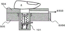
Fig. 8A shows a perspective view of a lancing device 800 according to a second embodiment. The blood collection device 800 includes a disk 501, a negative pressure device 503, a holder support 5011 for supporting the disk, and a lower holder support 5012. Further, a blood collection amount confirmation means 506 for confirming the amount of collected blood may be provided. The blood collection amount confirmation means 506 may be any means capable of measuring the amount of collected blood within the range of conventional techniques such as a pressure gauge and an optical sensor.
The disk 501 is composed of an upper surface disk 504 and a lower surface disk 505 which can be independently rotationally driven. The upper surface disk has at least one puncture hole 102 for pressing a finger to be punctured. The lower disc has at least one of the container portion 110 and the puncturing portion 101, and the positions of these portions can be switched by rotating the lower disc.
Fig. 8B shows a top view of the support 501 of fig. 8A. The lower disc 505 and the upper disc 504 are arranged concentrically, and the lower disc 505 is formed slightly larger. The upper surface disk 504 has at least one puncture hole 102, and the negative pressure device 503 is connected to the puncture hole 102 via a negative pressure flow path 508. The lower disc 505 is provided with rods 5055 and 5056, which are described later, and can be manually rotated clockwise and counterclockwise by gripping them.
FIG. 8C shows the A-A cross section of FIG. 8B. The piercing hole 102 and the negative pressure flow path 508 are formed on the upper surface disk 504 side. The negative pressure flow path 508 is formed by grooving the lower surface of the upper disc 504. The negative pressure device 503 is connected to the negative pressure flow path 508 via a connector 5034, a flow path 5035, and an openable and closable valve 5031. The negative pressure device 503 includes a pressure portion 5032 and a plunger 5033. The negative pressure device 503 closes the valve 5031, and when the plunger 5033 is pulled, the pressure portion 5032 becomes a negative pressure. Thereafter, the puncture hole 102 can be made negative by placing a finger in the puncture hole 102, opening the valve 5031, and connecting the negative pressure passage 508 to the passage 5035. The plunger may be moved manually or mechanically by a motor or the like.
FIG. 8D shows a section B-B of FIG. 8B. Between the upper surface disk 504 and the lower surface disk 505, a seal is provided by an O-ring 5041 so as not to generate a gap.
Fig. 9 shows a C-C section of fig. 8B. The container portion 110 and the puncturing portion 101 are attached to the lower disc 505. The container portion 110 and the puncture portion 101 are replaced each time blood is collected, and other structures such as the disk 501 are reused. Therefore, the container portion 110 and the puncturing portion 101 preferably have a cylindrical outer shape and are configured to be attachable to and detachable from the lower disc 505 through screw holes. The lower surface mount 505 is rotatable as shown in fig. 8B, and in the case of manual action, levers 5055 and 5056 are grasped for rotation. When the lower surface holder support 5012 and the holder support 5011 are automatically rotated, a lower surface disk drive motor is incorporated into the holder support 5011, and the lower surface holder 505 can be rotated by pressing a drive button 5013 (shown in fig. 8A) of the lower surface holder support 5012.
The operation of the blood collection device 800 will be described with reference to fig. 10 and 11. Fig. 11 shows a variation of the configuration of the B-B cross-sectional portion of fig. 8B. In fig. 11, the structure of the negative pressure device 503 is omitted.
In this embodiment, first, the negative pressure device 503 is operated before the finger is fixed (step 1001). To drive the negative pressure device 503, the valve 5031 is first closed, and the plunger 5033 is pulled, so that the pressure inside the pressure portion 5032 becomes negative.
Thereafter, the finger 4 is placed in the puncture 102 (step 1002), the valve 5031 is opened, the negative pressure passage 508 is connected to the passage 5035, and the space between the puncture 102 and the finger is made negative pressure.
Thereafter, the lever 5055 and the lever 5056 are grasped, and the lower surface holder 505 is rotated to position the puncture 101 below the puncture section 102 as shown in fig. 11A (step 1003). If the movement angle can be aligned by aligning the position of the rod 5056 with the position of the flow path 5035, the burden of position adjustment is reduced.
In this state, when the puncture rod 1021 provided in the puncture section 101 is pulled, the needle 1011 projects (step 1004, the state of fig. 11B). The needle 1011 is then returned into the puncturing part 101 by the biasing force of the spring (the state of fig. 11C).
Thereafter, the lower disc is rotated to align the rod 5055 shown in fig. 9A with the channel 5035 so that the container portion 110 is positioned below the puncture 102 (step 1005, state of fig. 12A). When left standing in this state, the blood 301 that has oozed out from the puncture trace under the influence of the negative pressure remains in the container of the container portion 110 (step 1006).
The blood collection amount confirmation means 506 confirms that the amount of blood 301 in the container is a required amount (step 1007). The method of confirming the blood collection amount confirming means 506 may be visual. Further, a small mirror 115 may be disposed at a graduated portion of the side wall of the container portion 110, a mirror 116 may be disposed below the container portion 110, and the blood collection amount may be measured by irradiating light or laser light from the blood collection amount confirmation mechanism 506 and monitoring the light using a camera or the like.
After a desired amount of blood is collected, the valve 5031 of the negative pressure device 503 is closed (shown in fig. 8C) (step 1008), and the finger 4 is removed from the puncture hole 102 (step 1009). A protective tape such as a protective band-aid is stuck to the puncture trace of the finger 4 (step 1010). Thereafter, the container portion 110 is removed from the holder 501 (step 1011), and is transported to an analysis device or a centrifuge as needed. Before the transportation, the container portion 110 may be covered with a cover 113B as shown in fig. 12B.
According to the present embodiment, since the puncture part 101, the container part 110, and the puncture hole part 102 are present on the same plane by using the rotatable holder 501, the puncture part 101, and the container part 110 can be accurately positioned in a short time, and a required amount of blood can be collected in a short time. Since the holder 501 is composed of the upper holder 504 and the lower holder 505, the holder support 5011, the lower holder support 5012, and the blood collection amount confirmation mechanism 506 are not contaminated by the blood 301 after the puncture. Therefore, the amount of blood lost is small, and a required amount of blood can be collected in a short time.
Example 3
Next, a third embodiment of the present invention will be described with reference to fig. 13 to 15.
In the third embodiment, as shown in fig. 13 to 15, the puncture portion 1400 is integrated with the container 1500 in the blood sampling device 1300, and the puncture portion 1400 has a through hole 1401, which is a modification of the first embodiment.
Fig. 13A is a perspective view of a blood-drawing device 1300. The blood collection device 1300 has a structure in which the puncture portion 1400 and the container 1500 are combined so as to be vertically overlapped. A transparent confirmation window 1402 is provided on the side surface of the puncturing part 1400, and the blood collection state of blood can be visually confirmed. An adhesive member 1403 such as a double-sided tape having adhesiveness is attached to at least a part of the outer wall of the puncturing part 1400. The adhesive member to be stuck on the puncture side has such an adhesive force that the fingers cannot move and the fingers can be easily peeled off. The puncturing part side may be formed of an elastic member, and the finger is configured to be easily attached to the puncturing hole 1404. The double-sided adhesive tape with adhesiveness is used for fixing the finger, so that the risk that the finger is deviated in the blood sampling process and blood is attached to the periphery can be reduced.
Fig. 13B is a perspective view of the internal structure of the puncturing part 1400. The puncture portion 1400 includes a needle 1410, and a plurality of through holes 1401, a puncture rib 1411, and a puncture portion support 1412 are provided below the needle 1410. The through hole 1401 is arranged to form a hole as large as possible around the needle 1410. The finger puncture is performed with the needle 1410. The puncturing part 1400 is disposed so as to reach the open end side of the container 1500 when the puncturing part 1400 is connected to the container 1500.
Fig. 13C is a perspective view of the container 1500. Container 1500 has open end 1501, closed end 1502, and container thread 1503, and blood flows in from the open end 1501 side and remains in closed end 1502. A blood collection confirmation unit 117 (see fig. 13E) is provided on the bottom surface of the closed end 1502.
Fig. 13D is a plan view of the blood sampling device 1300, and fig. 13E is a plan view of the puncture unit 101 obtained by removing the puncture driving unit 104 from the blood sampling device 3. FIG. 13F shows a D-D cross-section of FIG. 13D. The puncturing part 1400 includes springs 112 to 115 and a protrusion 1420 therein. The piercing portion 1400 and the container 1500 are detachably connected by a container screw portion 109.
The puncture portion 1400 accommodates a needle 1410 having a puncture rib 1411. One ends of the springs 113 and 115 are connected to the lower side surfaces of the piercing ribs 1411. The other ends of these springs are in contact with the upper surface of the container 1500, but are unconnected. As the container 1500 is gradually raised, the repulsive force of the springs 113 and 115 is transmitted to the piercing rib 1411, so that the needle 1410 is protruded. One ends of the springs 112 and 114 are connected to the upper surface of the pricking rib 1411, and the other ends of the springs are connected to the inner surface of the frame of the pricking part 1400. The springs 112, 114 press the piercing rib 1411 downward after the needle 1410 pierces a finger. Thereby disengaging the needle 1410 from the finger and beginning bleeding.
Fig. 14 shows an operation process of the blood collection device 3, and fig. 15A to C show a driving method of the blood collection device 1300 of the present invention.
The left index finger 4 is placed in the puncture hole 1404 in the puncture side 1403 of the blood collection device 1300. The container 1500 is then grasped by the right thumb and forefinger 4' of the hand other than the piercing site, rotated in the direction of the press-in thread, or the container 1500 is lifted upward (fig. 15A).
When the container 1500 is lifted upward, the puncturing rib 1411 is disengaged from the protrusion 1420 by the repulsive force of the springs 115 and 113 or by the pressing of the upper end surface of the container 1500, and as shown in fig. 15B, the puncturing part 101 protrudes from the puncturing hole 102 by the repulsive force of the contracted springs 113 and 115. Then, the needle 1410 penetrates the finger 4, and bleeding starts from the puncture trace of the finger 4.
After puncturing, as shown in fig. 15C, the needle 1410 of the puncturing part 101 is supported by the projection 1420, and the tip of the needle 1410 is adjusted to a distance such that the finger does not touch. Blood 301 is stored in the container 1500 by the diversion of the needle 1410. The blood collection confirmation unit 117 can confirm whether or not the amount of blood necessary for the test remains in the container 1500. The blood collection confirmation unit 117 confirms the same method as in example 2. The difference from embodiment 2 is that the blood sampling amount confirmation mechanism 506 is not provided. As in the container unit 110, a small mirror 10211 (shown in fig. 12B) is disposed at a position where a desired amount of scale is provided, and the mirror 10212 (shown in fig. 12) is positioned below the container unit 102 and visually confirmed. After a desired amount of sample is collected, the finger is removed from the blood sampling device 1300 and the lid is closed over the container 1500, as in fig. 12B. This prevents bacteria from being mixed into the air.
Thereafter, the container 1500 is transported to a centrifuge (not shown) and directly set in the centrifuge to be separated into serum and blood cells. The container 1500 may contain a pharmaceutical product such as a coagulant or a separating agent. When the separating agent is contained, the separation is performed by a centrifuge and then the product is transported to an analyzer (not shown). The blood-contacting container 1500, the through-hole 1401, and the puncture support 1412 may be coated with an anticoagulant, a coagulant, or the like according to the examination item.
The blood sampling device 1300 is disposable, and the material of the container is selected so that the material components do not elute into the blood and the material components do not rupture the blood cells so as not to affect the blood. As materials, polyethylene terephthalate, polyester, polyacrylonitrile, polymethyl methacrylate, polypropylene, polyethylene, polyamide, polystyrene, glass, silicon, and the like can be considered. The needle 1410 may be made of a material having a certain strength, such as metal or resin.
In this embodiment, since the puncturing part 1400 and the container 1500 are assembled into one instrument, blood can be collected into the container 1500 immediately after puncturing. Since the container 1500 is disposed just below the finger and the puncture portion 1400 has the through hole 1401, the minute amount of blood 301 discharged from the finger flows through the needle 1410 immediately after the puncture and is injected into the container 1500. Further, since the puncture hole 1404 is sealed with a finger at the time of blood collection, blood is not exposed to the outside of the container 1500, and there is no loss of blood and no scattering to the surroundings.
That is, blood does not splash out of the container from which the blood is collected, and blood can be collected in a short time after puncturing.
Description of the symbols
1: blood sampling device
2: fixing part
3: connecting body
4: finger(s)
110: movable container part
111: protrusion
112: container with a lid
113: cover
120: movable puncture part
121: protrusion
122: needle tip
123: needle portion connecting portion
124: needle holding part
125: shaft
130: drive fixing part
131: spring housing
132: pressure source
133: puncture part fixing part
134: positioning
140: driving part
141: sphygmomanometer
142: pressure device
201: finger upper surface fixing component
202: finger lower surface fixing component
203: pressing object
205: finger fixing support
206: lower surface support
207: pressure sensor
800: blood sampling device
501: disc with a circular groove
503: negative pressure device
504: upper side disc
505: lower disc
506: blood sampling amount confirming mechanism
508: negative pressure flow path
5055. 5056: rod
1300: blood sampling device
1400: puncture part
1401: through hole
1402: small window
1410: needle
1411: puncture rib
1500: a container.
Claims (8)
1. A blood collection device, comprising:
a movable container part having a puncture hole at a top part thereof, and having a container movable in a horizontal direction with respect to the movable container part, the container having an opening and a closing part, and holding the opening in an upward facing state;
a fixing portion for fixing a blood collection subject in a state facing the puncture portion;
a movable puncture unit which is located below the movable container unit and punctures the blood collection subject;
a drive fixing portion which is located below the movable puncture portion, has a spring housing portion and a pressure source for applying a negative pressure to the spring housing portion, and causes the movable puncture portion to puncture the blood collection target by expansion and contraction of a spring in the spring housing portion,
when the container is moved relative to the movable container portion so that the puncture hole portion and the spring housing portion are in a space communicating with each other, the pressure source is driven to generate a negative pressure in the spring housing portion and the puncture hole portion, and then the movable puncture portion punctures the blood collection subject.
2. The lancing device according to claim 1,
the movable container portion has a guide mechanism for sliding the container in a horizontal direction with respect to the movable container portion.
3. The lancing device according to claim 1,
a pressing member for pressing the blood sampling object is arranged on the fixing portion,
the blood sampling device is provided with a sphygmomanometer for measuring blood pressure while pressurizing a blood sampling object by the pressure object.
4. The lancing device according to claim 3,
the blood sampling device is provided with a pressurizing source that pressurizes a blood sampling subject such that the blood pressure obtained by the sphygmomanometer is not less than a minimum blood pressure and not more than a maximum blood pressure.
5. The lancing device according to claim 1,
has a cover for protecting a blood-collecting object after blood collection.
6. The lancing device according to claim 1,
the movable container portion, the fixed portion, and the movable puncture portion are all configured to be separable.
7. The lancing device according to claim 1,
the blood sampling device includes a confirmation unit for confirming a state of the blood stored in the container portion.
8. The lancing device according to any one of claims 1 to 7,
a transparent window is provided in at least a portion of the container.
Applications Claiming Priority (3)
| Application Number | Priority Date | Filing Date | Title |
|---|---|---|---|
| JP2015-121633 | 2015-06-17 | ||
| JP2015121633A JP6558971B2 (en) | 2015-06-17 | 2015-06-17 | Blood collection device |
| PCT/JP2016/063125 WO2016203853A1 (en) | 2015-06-17 | 2016-04-27 | Blood collector |
Publications (2)
| Publication Number | Publication Date |
|---|---|
| CN107708560A CN107708560A (en) | 2018-02-16 |
| CN107708560B true CN107708560B (en) | 2020-07-24 |
Family
ID=57545218
Family Applications (1)
| Application Number | Title | Priority Date | Filing Date |
|---|---|---|---|
| CN201680033834.XA Active CN107708560B (en) | 2015-06-17 | 2016-04-27 | Blood sampling device |
Country Status (5)
| Country | Link |
|---|---|
| US (1) | US10702199B2 (en) |
| EP (1) | EP3311742B1 (en) |
| JP (1) | JP6558971B2 (en) |
| CN (1) | CN107708560B (en) |
| WO (1) | WO2016203853A1 (en) |
Families Citing this family (17)
| Publication number | Priority date | Publication date | Assignee | Title |
|---|---|---|---|---|
| FI4035762T3 (en) | 2015-09-09 | 2023-12-04 | Drawbridge Health Inc | Devices for sample collection, stabilization and preservation |
| EP4059427B1 (en) | 2016-08-24 | 2024-03-20 | Becton, Dickinson and Company | A device for the attached flow of blood |
| SG10201911879UA (en) | 2017-01-10 | 2020-01-30 | Drawbridge Health Inc | Devices, systems, and methods for sample collection |
| JP6423025B2 (en) | 2017-01-17 | 2018-11-14 | 三菱伸銅株式会社 | Tin-plated copper terminal material excellent in insertion / removability and manufacturing method thereof |
| DE102017201440B3 (en) * | 2017-01-30 | 2018-05-30 | Fresenius Medical Care Deutschland Gmbh | Cannulation automat for the detection and manipulation of a blood vessel, and corresponding method |
| JP6994910B2 (en) * | 2017-11-13 | 2022-01-14 | 株式会社日立ハイテク | How to operate the blood collection device and blood collection device |
| CN108309324B (en) * | 2018-02-11 | 2021-03-26 | 河南科技大学第一附属医院 | Medical hand blood sampling fixer |
| KR102121995B1 (en) * | 2018-03-21 | 2020-06-11 | 주식회사 디더블유메디팜 | Apparatus for helping blood collection |
| WO2019189441A1 (en) * | 2018-03-30 | 2019-10-03 | テルモ株式会社 | Medical device |
| WO2019220340A1 (en) * | 2018-05-14 | 2019-11-21 | Qloudlab Sa | Sample collection device, system and method for extracting and collecting a sample of a fluid of a user |
| CN109394245A (en) * | 2018-11-29 | 2019-03-01 | 湖南图强科技开发有限公司 | A kind of fixed blood sampler of finger |
| BE1027338B1 (en) * | 2019-06-04 | 2021-01-14 | Inst Of Tropical Medicine | FINGER PRICKER COLLECTOR |
| JP7157711B2 (en) * | 2019-07-19 | 2022-10-20 | 株式会社日立ハイテク | Blood collection device |
| WO2021128154A1 (en) * | 2019-12-26 | 2021-07-01 | 郝云玲 | Peripheral blood collection device |
| CN112515669B (en) * | 2020-11-24 | 2021-07-09 | 为康(苏州)基因科技有限公司 | Gene detection quick sampling device |
| CN114543956B (en) * | 2021-11-24 | 2024-04-02 | 万向一二三股份公司 | Device and method for collecting and detecting free electrolyte amount of soft-package lithium battery |
| CN114052682B (en) * | 2021-12-14 | 2023-10-24 | 重庆科技学院 | Physiological parameter monitoring system based on raspberry group |
Family Cites Families (20)
| Publication number | Priority date | Publication date | Assignee | Title |
|---|---|---|---|---|
| US2442111A (en) * | 1946-05-06 | 1948-05-25 | Charles S Beardsley | Bandage |
| US4298011A (en) * | 1979-09-07 | 1981-11-03 | Mangurten Henry H | Blood sample collector |
| CA1253764A (en) * | 1984-11-20 | 1989-05-09 | Walter Sarstedt | Blood storage device |
| JP3393920B2 (en) | 1993-12-09 | 2003-04-07 | 富士写真フイルム株式会社 | Wearing equipment for small-volume fixed-volume blood sampling points |
| JPH09168530A (en) * | 1995-10-17 | 1997-06-30 | Dainippon Printing Co Ltd | Body fluid collecting tool and body fluid analyzer using the same |
| JP3605225B2 (en) * | 1996-04-01 | 2004-12-22 | 大日本印刷株式会社 | Body fluid analyzer |
| ATE408372T1 (en) * | 1999-01-04 | 2008-10-15 | Terumo Corp | LANDZET ARRANGEMENT FOR COLLECTION AND DETECTION OF BODY FLUID |
| JP2002219115A (en) | 2001-01-26 | 2002-08-06 | Matsushita Electric Works Ltd | Blood collecting device |
| EP1405595B2 (en) * | 2001-07-11 | 2010-09-01 | ARKRAY, Inc. | Piercing device |
| JP2005278740A (en) * | 2004-03-29 | 2005-10-13 | Citizen Watch Co Ltd | Blood collecting apparatus |
| KR20050117825A (en) * | 2004-06-11 | 2005-12-15 | 삼성전자주식회사 | Blood pressure measuring system and method of measuring blood pressure using the same |
| JP2006068384A (en) | 2004-09-03 | 2006-03-16 | Advance Co Ltd | Body fluid transfer implement, and body fluid inspecting system using the same |
| CA2624059C (en) | 2005-09-30 | 2019-04-02 | Intuity Medical, Inc. | Multi-site body fluid sampling and analysis cartridge |
| US8372015B2 (en) * | 2006-08-28 | 2013-02-12 | Intuity Medical, Inc. | Body fluid sampling device with pivotable catalyst member |
| JP2008054884A (en) * | 2006-08-30 | 2008-03-13 | Setsunan Univ | Apparatus and method for measuring sampled liquid |
| JP4195504B2 (en) * | 2006-12-27 | 2008-12-10 | 株式会社メディビック | Vacuum blood collection tube |
| WO2009081405A2 (en) * | 2007-12-25 | 2009-07-02 | Rapidx Ltd. | Devices and methods for reduced-pain blood sampling |
| CN201341885Y (en) * | 2008-12-31 | 2009-11-11 | 路明 | Terminal blood collecting pipe |
| KR101090730B1 (en) * | 2010-06-24 | 2011-12-08 | (주)일렉켐 | A module for gathering the blood for measure of alcohol concentration |
| CA2852070C (en) * | 2011-10-20 | 2017-12-19 | Becton, Dickinson And Company | Syringe with removable plunger for arterial blood gas sample collection |
-
2015
- 2015-06-17 JP JP2015121633A patent/JP6558971B2/en active Active
-
2016
- 2016-04-27 WO PCT/JP2016/063125 patent/WO2016203853A1/en active Application Filing
- 2016-04-27 CN CN201680033834.XA patent/CN107708560B/en active Active
- 2016-04-27 EP EP16811328.0A patent/EP3311742B1/en active Active
- 2016-04-27 US US15/579,957 patent/US10702199B2/en active Active
Also Published As
| Publication number | Publication date |
|---|---|
| EP3311742A1 (en) | 2018-04-25 |
| US20180220944A1 (en) | 2018-08-09 |
| US10702199B2 (en) | 2020-07-07 |
| EP3311742A4 (en) | 2019-03-06 |
| JP6558971B2 (en) | 2019-08-14 |
| JP2017006184A (en) | 2017-01-12 |
| CN107708560A (en) | 2018-02-16 |
| EP3311742B1 (en) | 2020-03-04 |
| WO2016203853A1 (en) | 2016-12-22 |
Similar Documents
| Publication | Publication Date | Title |
|---|---|---|
| CN107708560B (en) | Blood sampling device | |
| CN101288592B (en) | Analytical system for detecting an analyte in a body fluid and disposable integrated puncturing and analyzing element | |
| JP7438137B2 (en) | Sample collection devices, systems, and methods for extracting and collecting samples of user fluids | |
| US8007445B2 (en) | Analytical aid | |
| CA2909183C (en) | Blood sampling transfer device | |
| US20050101981A1 (en) | Method and apparatus for lancet launching device intergrated onto a blood-sampling cartridge | |
| JP2017042641A (en) | System and interface for blood sampling | |
| CA2909263C (en) | Biological fluid sampling transfer device and biological fluid separation and testing system | |
| US8846333B2 (en) | Method and device for visual detection of hemolysis | |
| KR20040070311A (en) | Sample testing device | |
| US20130317323A1 (en) | Decompression mechanism, puncturing apparatus, and blood analysis apparatus | |
| US20230146889A1 (en) | Sample collection device, system and method for extracting and collecting a sample of a fluid of a user | |
| CN114126485B (en) | Blood sampling device | |
| US8172866B2 (en) | Medical aid | |
| CN111936866A (en) | Sampling mechanism and sampling method |
Legal Events
| Date | Code | Title | Description |
|---|---|---|---|
| PB01 | Publication | ||
| PB01 | Publication | ||
| SE01 | Entry into force of request for substantive examination | ||
| SE01 | Entry into force of request for substantive examination | ||
| GR01 | Patent grant | ||
| GR01 | Patent grant |