CN107667007B - Sandwich arrangement with ceramic faceplates and ceramic felt - Google Patents
Sandwich arrangement with ceramic faceplates and ceramic felt Download PDFInfo
- Publication number
- CN107667007B CN107667007B CN201680033201.9A CN201680033201A CN107667007B CN 107667007 B CN107667007 B CN 107667007B CN 201680033201 A CN201680033201 A CN 201680033201A CN 107667007 B CN107667007 B CN 107667007B
- Authority
- CN
- China
- Prior art keywords
- ceramic
- sandwich arrangement
- cmc
- arrangement according
- fibers
- Prior art date
- Legal status (The legal status is an assumption and is not a legal conclusion. Google has not performed a legal analysis and makes no representation as to the accuracy of the status listed.)
- Active
Links
- 239000000919 ceramic Substances 0.000 title claims abstract description 137
- 239000000835 fiber Substances 0.000 claims abstract description 65
- 239000000463 material Substances 0.000 claims abstract description 45
- 239000004753 textile Substances 0.000 claims abstract description 23
- 239000000203 mixture Substances 0.000 claims abstract description 8
- 238000001816 cooling Methods 0.000 claims description 57
- 238000000034 method Methods 0.000 claims description 16
- 239000011159 matrix material Substances 0.000 claims description 14
- 229910010293 ceramic material Inorganic materials 0.000 claims description 9
- 238000000576 coating method Methods 0.000 claims description 7
- 239000002826 coolant Substances 0.000 claims description 6
- 230000001788 irregular Effects 0.000 claims description 3
- 230000035699 permeability Effects 0.000 claims description 3
- 239000002002 slurry Substances 0.000 claims description 2
- 239000011153 ceramic matrix composite Substances 0.000 description 99
- 239000010410 layer Substances 0.000 description 84
- 239000002184 metal Substances 0.000 description 27
- 229910052751 metal Inorganic materials 0.000 description 27
- 239000007789 gas Substances 0.000 description 19
- 125000006850 spacer group Chemical group 0.000 description 10
- 239000002131 composite material Substances 0.000 description 8
- 230000036961 partial effect Effects 0.000 description 7
- 238000013461 design Methods 0.000 description 6
- 238000004519 manufacturing process Methods 0.000 description 6
- 230000004888 barrier function Effects 0.000 description 5
- 239000011248 coating agent Substances 0.000 description 5
- 230000008569 process Effects 0.000 description 5
- 229910000679 solder Inorganic materials 0.000 description 5
- 238000005476 soldering Methods 0.000 description 5
- 238000005219 brazing Methods 0.000 description 4
- 239000004568 cement Substances 0.000 description 4
- 230000006378 damage Effects 0.000 description 4
- 239000004744 fabric Substances 0.000 description 4
- 238000010438 heat treatment Methods 0.000 description 4
- 230000003647 oxidation Effects 0.000 description 4
- 238000007254 oxidation reaction Methods 0.000 description 4
- 239000011253 protective coating Substances 0.000 description 4
- 230000003014 reinforcing effect Effects 0.000 description 4
- 230000015556 catabolic process Effects 0.000 description 3
- 230000007613 environmental effect Effects 0.000 description 3
- 239000011229 interlayer Substances 0.000 description 3
- 239000000758 substrate Substances 0.000 description 3
- 239000002759 woven fabric Substances 0.000 description 3
- PXHVJJICTQNCMI-UHFFFAOYSA-N Nickel Chemical compound [Ni] PXHVJJICTQNCMI-UHFFFAOYSA-N 0.000 description 2
- 238000004026 adhesive bonding Methods 0.000 description 2
- 230000015572 biosynthetic process Effects 0.000 description 2
- 150000001875 compounds Chemical class 0.000 description 2
- 230000007812 deficiency Effects 0.000 description 2
- 238000006731 degradation reaction Methods 0.000 description 2
- 238000001035 drying Methods 0.000 description 2
- 230000001747 exhibiting effect Effects 0.000 description 2
- 239000002657 fibrous material Substances 0.000 description 2
- 238000009413 insulation Methods 0.000 description 2
- 230000010354 integration Effects 0.000 description 2
- 229910001092 metal group alloy Inorganic materials 0.000 description 2
- 239000008188 pellet Substances 0.000 description 2
- 229920000642 polymer Polymers 0.000 description 2
- 239000011148 porous material Substances 0.000 description 2
- 238000000926 separation method Methods 0.000 description 2
- 238000005245 sintering Methods 0.000 description 2
- 239000000126 substance Substances 0.000 description 2
- 230000000930 thermomechanical effect Effects 0.000 description 2
- 229920000049 Carbon (fiber) Polymers 0.000 description 1
- 229920002134 Carboxymethyl cellulose Polymers 0.000 description 1
- 239000000853 adhesive Substances 0.000 description 1
- 230000001070 adhesive effect Effects 0.000 description 1
- 238000013459 approach Methods 0.000 description 1
- 230000009286 beneficial effect Effects 0.000 description 1
- 239000004917 carbon fiber Substances 0.000 description 1
- 235000010948 carboxy methyl cellulose Nutrition 0.000 description 1
- 229920006184 cellulose methylcellulose Polymers 0.000 description 1
- 238000012710 chemistry, manufacturing and control Methods 0.000 description 1
- 238000010276 construction Methods 0.000 description 1
- 230000007797 corrosion Effects 0.000 description 1
- 238000005260 corrosion Methods 0.000 description 1
- 238000005520 cutting process Methods 0.000 description 1
- 125000004122 cyclic group Chemical group 0.000 description 1
- 230000007547 defect Effects 0.000 description 1
- 230000032798 delamination Effects 0.000 description 1
- 238000011161 development Methods 0.000 description 1
- 238000009826 distribution Methods 0.000 description 1
- 230000000694 effects Effects 0.000 description 1
- 238000004870 electrical engineering Methods 0.000 description 1
- 230000008030 elimination Effects 0.000 description 1
- 238000003379 elimination reaction Methods 0.000 description 1
- 230000003628 erosive effect Effects 0.000 description 1
- 238000007749 high velocity oxygen fuel spraying Methods 0.000 description 1
- 239000012943 hotmelt Substances 0.000 description 1
- 238000007654 immersion Methods 0.000 description 1
- 230000002401 inhibitory effect Effects 0.000 description 1
- 239000012784 inorganic fiber Substances 0.000 description 1
- 238000009434 installation Methods 0.000 description 1
- 238000003754 machining Methods 0.000 description 1
- 238000000465 moulding Methods 0.000 description 1
- 229910052759 nickel Inorganic materials 0.000 description 1
- 229910052575 non-oxide ceramic Inorganic materials 0.000 description 1
- 239000011225 non-oxide ceramic Substances 0.000 description 1
- 238000012856 packing Methods 0.000 description 1
- 239000002245 particle Substances 0.000 description 1
- 235000015927 pasta Nutrition 0.000 description 1
- 238000003825 pressing Methods 0.000 description 1
- 238000007639 printing Methods 0.000 description 1
- 238000012545 processing Methods 0.000 description 1
- 230000002035 prolonged effect Effects 0.000 description 1
- 230000001681 protective effect Effects 0.000 description 1
- 230000002829 reductive effect Effects 0.000 description 1
- 238000002407 reforming Methods 0.000 description 1
- 230000002787 reinforcement Effects 0.000 description 1
- 230000008439 repair process Effects 0.000 description 1
- 239000002356 single layer Substances 0.000 description 1
- 239000007921 spray Substances 0.000 description 1
- 229910000601 superalloy Inorganic materials 0.000 description 1
- 239000012720 thermal barrier coating Substances 0.000 description 1
- 238000012546 transfer Methods 0.000 description 1
- 210000001170 unmyelinated nerve fiber Anatomy 0.000 description 1
Images


Classifications
-
- B—PERFORMING OPERATIONS; TRANSPORTING
- B32—LAYERED PRODUCTS
- B32B—LAYERED PRODUCTS, i.e. PRODUCTS BUILT-UP OF STRATA OF FLAT OR NON-FLAT, e.g. CELLULAR OR HONEYCOMB, FORM
- B32B5/00—Layered products characterised by the non- homogeneity or physical structure, i.e. comprising a fibrous, filamentary, particulate or foam layer; Layered products characterised by having a layer differing constitutionally or physically in different parts
- B32B5/02—Layered products characterised by the non- homogeneity or physical structure, i.e. comprising a fibrous, filamentary, particulate or foam layer; Layered products characterised by having a layer differing constitutionally or physically in different parts characterised by structural features of a fibrous or filamentary layer
- B32B5/022—Non-woven fabric
-
- B—PERFORMING OPERATIONS; TRANSPORTING
- B32—LAYERED PRODUCTS
- B32B—LAYERED PRODUCTS, i.e. PRODUCTS BUILT-UP OF STRATA OF FLAT OR NON-FLAT, e.g. CELLULAR OR HONEYCOMB, FORM
- B32B1/00—Layered products having a non-planar shape
-
- B—PERFORMING OPERATIONS; TRANSPORTING
- B32—LAYERED PRODUCTS
- B32B—LAYERED PRODUCTS, i.e. PRODUCTS BUILT-UP OF STRATA OF FLAT OR NON-FLAT, e.g. CELLULAR OR HONEYCOMB, FORM
- B32B15/00—Layered products comprising a layer of metal
- B32B15/02—Layer formed of wires, e.g. mesh
-
- B—PERFORMING OPERATIONS; TRANSPORTING
- B32—LAYERED PRODUCTS
- B32B—LAYERED PRODUCTS, i.e. PRODUCTS BUILT-UP OF STRATA OF FLAT OR NON-FLAT, e.g. CELLULAR OR HONEYCOMB, FORM
- B32B15/00—Layered products comprising a layer of metal
- B32B15/04—Layered products comprising a layer of metal comprising metal as the main or only constituent of a layer, which is next to another layer of the same or of a different material
-
- B—PERFORMING OPERATIONS; TRANSPORTING
- B32—LAYERED PRODUCTS
- B32B—LAYERED PRODUCTS, i.e. PRODUCTS BUILT-UP OF STRATA OF FLAT OR NON-FLAT, e.g. CELLULAR OR HONEYCOMB, FORM
- B32B15/00—Layered products comprising a layer of metal
- B32B15/14—Layered products comprising a layer of metal next to a fibrous or filamentary layer
-
- B—PERFORMING OPERATIONS; TRANSPORTING
- B32—LAYERED PRODUCTS
- B32B—LAYERED PRODUCTS, i.e. PRODUCTS BUILT-UP OF STRATA OF FLAT OR NON-FLAT, e.g. CELLULAR OR HONEYCOMB, FORM
- B32B18/00—Layered products essentially comprising ceramics, e.g. refractory products
-
- B—PERFORMING OPERATIONS; TRANSPORTING
- B32—LAYERED PRODUCTS
- B32B—LAYERED PRODUCTS, i.e. PRODUCTS BUILT-UP OF STRATA OF FLAT OR NON-FLAT, e.g. CELLULAR OR HONEYCOMB, FORM
- B32B3/00—Layered products comprising a layer with external or internal discontinuities or unevennesses, or a layer of non-planar shape; Layered products comprising a layer having particular features of form
- B32B3/02—Layered products comprising a layer with external or internal discontinuities or unevennesses, or a layer of non-planar shape; Layered products comprising a layer having particular features of form characterised by features of form at particular places, e.g. in edge regions
- B32B3/04—Layered products comprising a layer with external or internal discontinuities or unevennesses, or a layer of non-planar shape; Layered products comprising a layer having particular features of form characterised by features of form at particular places, e.g. in edge regions characterised by at least one layer folded at the edge, e.g. over another layer ; characterised by at least one layer enveloping or enclosing a material
-
- B—PERFORMING OPERATIONS; TRANSPORTING
- B32—LAYERED PRODUCTS
- B32B—LAYERED PRODUCTS, i.e. PRODUCTS BUILT-UP OF STRATA OF FLAT OR NON-FLAT, e.g. CELLULAR OR HONEYCOMB, FORM
- B32B3/00—Layered products comprising a layer with external or internal discontinuities or unevennesses, or a layer of non-planar shape; Layered products comprising a layer having particular features of form
- B32B3/26—Layered products comprising a layer with external or internal discontinuities or unevennesses, or a layer of non-planar shape; Layered products comprising a layer having particular features of form characterised by a particular shape of the outline of the cross-section of a continuous layer; characterised by a layer with cavities or internal voids ; characterised by an apertured layer
- B32B3/28—Layered products comprising a layer with external or internal discontinuities or unevennesses, or a layer of non-planar shape; Layered products comprising a layer having particular features of form characterised by a particular shape of the outline of the cross-section of a continuous layer; characterised by a layer with cavities or internal voids ; characterised by an apertured layer characterised by a layer comprising a deformed thin sheet, i.e. the layer having its entire thickness deformed out of the plane, e.g. corrugated, crumpled
-
- B—PERFORMING OPERATIONS; TRANSPORTING
- B32—LAYERED PRODUCTS
- B32B—LAYERED PRODUCTS, i.e. PRODUCTS BUILT-UP OF STRATA OF FLAT OR NON-FLAT, e.g. CELLULAR OR HONEYCOMB, FORM
- B32B5/00—Layered products characterised by the non- homogeneity or physical structure, i.e. comprising a fibrous, filamentary, particulate or foam layer; Layered products characterised by having a layer differing constitutionally or physically in different parts
- B32B5/02—Layered products characterised by the non- homogeneity or physical structure, i.e. comprising a fibrous, filamentary, particulate or foam layer; Layered products characterised by having a layer differing constitutionally or physically in different parts characterised by structural features of a fibrous or filamentary layer
- B32B5/024—Woven fabric
-
- B—PERFORMING OPERATIONS; TRANSPORTING
- B32—LAYERED PRODUCTS
- B32B—LAYERED PRODUCTS, i.e. PRODUCTS BUILT-UP OF STRATA OF FLAT OR NON-FLAT, e.g. CELLULAR OR HONEYCOMB, FORM
- B32B5/00—Layered products characterised by the non- homogeneity or physical structure, i.e. comprising a fibrous, filamentary, particulate or foam layer; Layered products characterised by having a layer differing constitutionally or physically in different parts
- B32B5/02—Layered products characterised by the non- homogeneity or physical structure, i.e. comprising a fibrous, filamentary, particulate or foam layer; Layered products characterised by having a layer differing constitutionally or physically in different parts characterised by structural features of a fibrous or filamentary layer
- B32B5/08—Layered products characterised by the non- homogeneity or physical structure, i.e. comprising a fibrous, filamentary, particulate or foam layer; Layered products characterised by having a layer differing constitutionally or physically in different parts characterised by structural features of a fibrous or filamentary layer the fibres or filaments of a layer being of different substances, e.g. conjugate fibres, mixture of different fibres
-
- B—PERFORMING OPERATIONS; TRANSPORTING
- B32—LAYERED PRODUCTS
- B32B—LAYERED PRODUCTS, i.e. PRODUCTS BUILT-UP OF STRATA OF FLAT OR NON-FLAT, e.g. CELLULAR OR HONEYCOMB, FORM
- B32B5/00—Layered products characterised by the non- homogeneity or physical structure, i.e. comprising a fibrous, filamentary, particulate or foam layer; Layered products characterised by having a layer differing constitutionally or physically in different parts
- B32B5/14—Layered products characterised by the non- homogeneity or physical structure, i.e. comprising a fibrous, filamentary, particulate or foam layer; Layered products characterised by having a layer differing constitutionally or physically in different parts characterised by a layer differing constitutionally or physically in different parts, e.g. denser near its faces
- B32B5/142—Variation across the area of the layer
-
- B—PERFORMING OPERATIONS; TRANSPORTING
- B32—LAYERED PRODUCTS
- B32B—LAYERED PRODUCTS, i.e. PRODUCTS BUILT-UP OF STRATA OF FLAT OR NON-FLAT, e.g. CELLULAR OR HONEYCOMB, FORM
- B32B5/00—Layered products characterised by the non- homogeneity or physical structure, i.e. comprising a fibrous, filamentary, particulate or foam layer; Layered products characterised by having a layer differing constitutionally or physically in different parts
- B32B5/14—Layered products characterised by the non- homogeneity or physical structure, i.e. comprising a fibrous, filamentary, particulate or foam layer; Layered products characterised by having a layer differing constitutionally or physically in different parts characterised by a layer differing constitutionally or physically in different parts, e.g. denser near its faces
- B32B5/145—Variation across the thickness of the layer
-
- B—PERFORMING OPERATIONS; TRANSPORTING
- B32—LAYERED PRODUCTS
- B32B—LAYERED PRODUCTS, i.e. PRODUCTS BUILT-UP OF STRATA OF FLAT OR NON-FLAT, e.g. CELLULAR OR HONEYCOMB, FORM
- B32B5/00—Layered products characterised by the non- homogeneity or physical structure, i.e. comprising a fibrous, filamentary, particulate or foam layer; Layered products characterised by having a layer differing constitutionally or physically in different parts
- B32B5/22—Layered products characterised by the non- homogeneity or physical structure, i.e. comprising a fibrous, filamentary, particulate or foam layer; Layered products characterised by having a layer differing constitutionally or physically in different parts characterised by the presence of two or more layers which are next to each other and are fibrous, filamentary, formed of particles or foamed
- B32B5/24—Layered products characterised by the non- homogeneity or physical structure, i.e. comprising a fibrous, filamentary, particulate or foam layer; Layered products characterised by having a layer differing constitutionally or physically in different parts characterised by the presence of two or more layers which are next to each other and are fibrous, filamentary, formed of particles or foamed one layer being a fibrous or filamentary layer
- B32B5/26—Layered products characterised by the non- homogeneity or physical structure, i.e. comprising a fibrous, filamentary, particulate or foam layer; Layered products characterised by having a layer differing constitutionally or physically in different parts characterised by the presence of two or more layers which are next to each other and are fibrous, filamentary, formed of particles or foamed one layer being a fibrous or filamentary layer another layer next to it also being fibrous or filamentary
-
- B—PERFORMING OPERATIONS; TRANSPORTING
- B32—LAYERED PRODUCTS
- B32B—LAYERED PRODUCTS, i.e. PRODUCTS BUILT-UP OF STRATA OF FLAT OR NON-FLAT, e.g. CELLULAR OR HONEYCOMB, FORM
- B32B7/00—Layered products characterised by the relation between layers; Layered products characterised by the relative orientation of features between layers, or by the relative values of a measurable parameter between layers, i.e. products comprising layers having different physical, chemical or physicochemical properties; Layered products characterised by the interconnection of layers
- B32B7/04—Interconnection of layers
- B32B7/12—Interconnection of layers using interposed adhesives or interposed materials with bonding properties
-
- C—CHEMISTRY; METALLURGY
- C04—CEMENTS; CONCRETE; ARTIFICIAL STONE; CERAMICS; REFRACTORIES
- C04B—LIME, MAGNESIA; SLAG; CEMENTS; COMPOSITIONS THEREOF, e.g. MORTARS, CONCRETE OR LIKE BUILDING MATERIALS; ARTIFICIAL STONE; CERAMICS; REFRACTORIES; TREATMENT OF NATURAL STONE
- C04B37/00—Joining burned ceramic articles with other burned ceramic articles or other articles by heating
- C04B37/003—Joining burned ceramic articles with other burned ceramic articles or other articles by heating by means of an interlayer consisting of a combination of materials selected from glass, or ceramic material with metals, metal oxides or metal salts
- C04B37/005—Joining burned ceramic articles with other burned ceramic articles or other articles by heating by means of an interlayer consisting of a combination of materials selected from glass, or ceramic material with metals, metal oxides or metal salts consisting of glass or ceramic material
-
- C—CHEMISTRY; METALLURGY
- C04—CEMENTS; CONCRETE; ARTIFICIAL STONE; CERAMICS; REFRACTORIES
- C04B—LIME, MAGNESIA; SLAG; CEMENTS; COMPOSITIONS THEREOF, e.g. MORTARS, CONCRETE OR LIKE BUILDING MATERIALS; ARTIFICIAL STONE; CERAMICS; REFRACTORIES; TREATMENT OF NATURAL STONE
- C04B37/00—Joining burned ceramic articles with other burned ceramic articles or other articles by heating
- C04B37/008—Joining burned ceramic articles with other burned ceramic articles or other articles by heating by means of an interlayer consisting of an organic adhesive, e.g. phenol resin or pitch
-
- F—MECHANICAL ENGINEERING; LIGHTING; HEATING; WEAPONS; BLASTING
- F01—MACHINES OR ENGINES IN GENERAL; ENGINE PLANTS IN GENERAL; STEAM ENGINES
- F01D—NON-POSITIVE DISPLACEMENT MACHINES OR ENGINES, e.g. STEAM TURBINES
- F01D5/00—Blades; Blade-carrying members; Heating, heat-insulating, cooling or antivibration means on the blades or the members
- F01D5/12—Blades
- F01D5/14—Form or construction
- F01D5/18—Hollow blades, i.e. blades with cooling or heating channels or cavities; Heating, heat-insulating or cooling means on blades
- F01D5/186—Film cooling
-
- F—MECHANICAL ENGINEERING; LIGHTING; HEATING; WEAPONS; BLASTING
- F01—MACHINES OR ENGINES IN GENERAL; ENGINE PLANTS IN GENERAL; STEAM ENGINES
- F01D—NON-POSITIVE DISPLACEMENT MACHINES OR ENGINES, e.g. STEAM TURBINES
- F01D5/00—Blades; Blade-carrying members; Heating, heat-insulating, cooling or antivibration means on the blades or the members
- F01D5/12—Blades
- F01D5/14—Form or construction
- F01D5/18—Hollow blades, i.e. blades with cooling or heating channels or cavities; Heating, heat-insulating or cooling means on blades
- F01D5/187—Convection cooling
- F01D5/188—Convection cooling with an insert in the blade cavity to guide the cooling fluid, e.g. forming a separation wall
- F01D5/189—Convection cooling with an insert in the blade cavity to guide the cooling fluid, e.g. forming a separation wall the insert having a tubular cross-section, e.g. airfoil shape
-
- F—MECHANICAL ENGINEERING; LIGHTING; HEATING; WEAPONS; BLASTING
- F01—MACHINES OR ENGINES IN GENERAL; ENGINE PLANTS IN GENERAL; STEAM ENGINES
- F01D—NON-POSITIVE DISPLACEMENT MACHINES OR ENGINES, e.g. STEAM TURBINES
- F01D5/00—Blades; Blade-carrying members; Heating, heat-insulating, cooling or antivibration means on the blades or the members
- F01D5/12—Blades
- F01D5/28—Selecting particular materials; Particular measures relating thereto; Measures against erosion or corrosion
- F01D5/282—Selecting composite materials, e.g. blades with reinforcing filaments
-
- F—MECHANICAL ENGINEERING; LIGHTING; HEATING; WEAPONS; BLASTING
- F01—MACHINES OR ENGINES IN GENERAL; ENGINE PLANTS IN GENERAL; STEAM ENGINES
- F01D—NON-POSITIVE DISPLACEMENT MACHINES OR ENGINES, e.g. STEAM TURBINES
- F01D5/00—Blades; Blade-carrying members; Heating, heat-insulating, cooling or antivibration means on the blades or the members
- F01D5/12—Blades
- F01D5/28—Selecting particular materials; Particular measures relating thereto; Measures against erosion or corrosion
- F01D5/284—Selection of ceramic materials
-
- B—PERFORMING OPERATIONS; TRANSPORTING
- B32—LAYERED PRODUCTS
- B32B—LAYERED PRODUCTS, i.e. PRODUCTS BUILT-UP OF STRATA OF FLAT OR NON-FLAT, e.g. CELLULAR OR HONEYCOMB, FORM
- B32B2250/00—Layers arrangement
- B32B2250/40—Symmetrical or sandwich layers, e.g. ABA, ABCBA, ABCCBA
-
- B—PERFORMING OPERATIONS; TRANSPORTING
- B32—LAYERED PRODUCTS
- B32B—LAYERED PRODUCTS, i.e. PRODUCTS BUILT-UP OF STRATA OF FLAT OR NON-FLAT, e.g. CELLULAR OR HONEYCOMB, FORM
- B32B2255/00—Coating on the layer surface
- B32B2255/02—Coating on the layer surface on fibrous or filamentary layer
-
- B—PERFORMING OPERATIONS; TRANSPORTING
- B32—LAYERED PRODUCTS
- B32B—LAYERED PRODUCTS, i.e. PRODUCTS BUILT-UP OF STRATA OF FLAT OR NON-FLAT, e.g. CELLULAR OR HONEYCOMB, FORM
- B32B2260/00—Layered product comprising an impregnated, embedded, or bonded layer wherein the layer comprises an impregnation, embedding, or binder material
- B32B2260/02—Composition of the impregnated, bonded or embedded layer
- B32B2260/021—Fibrous or filamentary layer
- B32B2260/023—Two or more layers
-
- B—PERFORMING OPERATIONS; TRANSPORTING
- B32—LAYERED PRODUCTS
- B32B—LAYERED PRODUCTS, i.e. PRODUCTS BUILT-UP OF STRATA OF FLAT OR NON-FLAT, e.g. CELLULAR OR HONEYCOMB, FORM
- B32B2262/00—Composition or structural features of fibres which form a fibrous or filamentary layer or are present as additives
- B32B2262/10—Inorganic fibres
- B32B2262/105—Ceramic fibres
-
- B—PERFORMING OPERATIONS; TRANSPORTING
- B32—LAYERED PRODUCTS
- B32B—LAYERED PRODUCTS, i.e. PRODUCTS BUILT-UP OF STRATA OF FLAT OR NON-FLAT, e.g. CELLULAR OR HONEYCOMB, FORM
- B32B2262/00—Composition or structural features of fibres which form a fibrous or filamentary layer or are present as additives
- B32B2262/10—Inorganic fibres
- B32B2262/106—Carbon fibres, e.g. graphite fibres
-
- B—PERFORMING OPERATIONS; TRANSPORTING
- B32—LAYERED PRODUCTS
- B32B—LAYERED PRODUCTS, i.e. PRODUCTS BUILT-UP OF STRATA OF FLAT OR NON-FLAT, e.g. CELLULAR OR HONEYCOMB, FORM
- B32B2262/00—Composition or structural features of fibres which form a fibrous or filamentary layer or are present as additives
- B32B2262/14—Mixture of at least two fibres made of different materials
-
- B—PERFORMING OPERATIONS; TRANSPORTING
- B32—LAYERED PRODUCTS
- B32B—LAYERED PRODUCTS, i.e. PRODUCTS BUILT-UP OF STRATA OF FLAT OR NON-FLAT, e.g. CELLULAR OR HONEYCOMB, FORM
- B32B2307/00—Properties of the layers or laminate
- B32B2307/30—Properties of the layers or laminate having particular thermal properties
- B32B2307/304—Insulating
-
- B—PERFORMING OPERATIONS; TRANSPORTING
- B32—LAYERED PRODUCTS
- B32B—LAYERED PRODUCTS, i.e. PRODUCTS BUILT-UP OF STRATA OF FLAT OR NON-FLAT, e.g. CELLULAR OR HONEYCOMB, FORM
- B32B2307/00—Properties of the layers or laminate
- B32B2307/30—Properties of the layers or laminate having particular thermal properties
- B32B2307/306—Resistant to heat
-
- B—PERFORMING OPERATIONS; TRANSPORTING
- B32—LAYERED PRODUCTS
- B32B—LAYERED PRODUCTS, i.e. PRODUCTS BUILT-UP OF STRATA OF FLAT OR NON-FLAT, e.g. CELLULAR OR HONEYCOMB, FORM
- B32B2307/00—Properties of the layers or laminate
- B32B2307/50—Properties of the layers or laminate having particular mechanical properties
- B32B2307/546—Flexural strength; Flexion stiffness
-
- B—PERFORMING OPERATIONS; TRANSPORTING
- B32—LAYERED PRODUCTS
- B32B—LAYERED PRODUCTS, i.e. PRODUCTS BUILT-UP OF STRATA OF FLAT OR NON-FLAT, e.g. CELLULAR OR HONEYCOMB, FORM
- B32B2307/00—Properties of the layers or laminate
- B32B2307/70—Other properties
- B32B2307/714—Inert, i.e. inert to chemical degradation, corrosion
-
- B—PERFORMING OPERATIONS; TRANSPORTING
- B32—LAYERED PRODUCTS
- B32B—LAYERED PRODUCTS, i.e. PRODUCTS BUILT-UP OF STRATA OF FLAT OR NON-FLAT, e.g. CELLULAR OR HONEYCOMB, FORM
- B32B2307/00—Properties of the layers or laminate
- B32B2307/70—Other properties
- B32B2307/724—Permeability to gases, adsorption
-
- B—PERFORMING OPERATIONS; TRANSPORTING
- B32—LAYERED PRODUCTS
- B32B—LAYERED PRODUCTS, i.e. PRODUCTS BUILT-UP OF STRATA OF FLAT OR NON-FLAT, e.g. CELLULAR OR HONEYCOMB, FORM
- B32B2603/00—Vanes, blades, propellers, rotors with blades
-
- B—PERFORMING OPERATIONS; TRANSPORTING
- B32—LAYERED PRODUCTS
- B32B—LAYERED PRODUCTS, i.e. PRODUCTS BUILT-UP OF STRATA OF FLAT OR NON-FLAT, e.g. CELLULAR OR HONEYCOMB, FORM
- B32B2607/00—Walls, panels
-
- C—CHEMISTRY; METALLURGY
- C04—CEMENTS; CONCRETE; ARTIFICIAL STONE; CERAMICS; REFRACTORIES
- C04B—LIME, MAGNESIA; SLAG; CEMENTS; COMPOSITIONS THEREOF, e.g. MORTARS, CONCRETE OR LIKE BUILDING MATERIALS; ARTIFICIAL STONE; CERAMICS; REFRACTORIES; TREATMENT OF NATURAL STONE
- C04B2235/00—Aspects relating to ceramic starting mixtures or sintered ceramic products
- C04B2235/02—Composition of constituents of the starting material or of secondary phases of the final product
- C04B2235/50—Constituents or additives of the starting mixture chosen for their shape or used because of their shape or their physical appearance
- C04B2235/52—Constituents or additives characterised by their shapes
- C04B2235/5208—Fibers
- C04B2235/5252—Fibers having a specific pre-form
- C04B2235/5256—Two-dimensional, e.g. woven structures
-
- C—CHEMISTRY; METALLURGY
- C04—CEMENTS; CONCRETE; ARTIFICIAL STONE; CERAMICS; REFRACTORIES
- C04B—LIME, MAGNESIA; SLAG; CEMENTS; COMPOSITIONS THEREOF, e.g. MORTARS, CONCRETE OR LIKE BUILDING MATERIALS; ARTIFICIAL STONE; CERAMICS; REFRACTORIES; TREATMENT OF NATURAL STONE
- C04B2235/00—Aspects relating to ceramic starting mixtures or sintered ceramic products
- C04B2235/60—Aspects relating to the preparation, properties or mechanical treatment of green bodies or pre-forms
- C04B2235/602—Making the green bodies or pre-forms by moulding
- C04B2235/6028—Shaping around a core which is removed later
-
- C—CHEMISTRY; METALLURGY
- C04—CEMENTS; CONCRETE; ARTIFICIAL STONE; CERAMICS; REFRACTORIES
- C04B—LIME, MAGNESIA; SLAG; CEMENTS; COMPOSITIONS THEREOF, e.g. MORTARS, CONCRETE OR LIKE BUILDING MATERIALS; ARTIFICIAL STONE; CERAMICS; REFRACTORIES; TREATMENT OF NATURAL STONE
- C04B2237/00—Aspects relating to ceramic laminates or to joining of ceramic articles with other articles by heating
- C04B2237/02—Aspects relating to interlayers, e.g. used to join ceramic articles with other articles by heating
- C04B2237/04—Ceramic interlayers
-
- C—CHEMISTRY; METALLURGY
- C04—CEMENTS; CONCRETE; ARTIFICIAL STONE; CERAMICS; REFRACTORIES
- C04B—LIME, MAGNESIA; SLAG; CEMENTS; COMPOSITIONS THEREOF, e.g. MORTARS, CONCRETE OR LIKE BUILDING MATERIALS; ARTIFICIAL STONE; CERAMICS; REFRACTORIES; TREATMENT OF NATURAL STONE
- C04B2237/00—Aspects relating to ceramic laminates or to joining of ceramic articles with other articles by heating
- C04B2237/30—Composition of layers of ceramic laminates or of ceramic or metallic articles to be joined by heating, e.g. Si substrates
- C04B2237/32—Ceramic
- C04B2237/38—Fiber or whisker reinforced
-
- C—CHEMISTRY; METALLURGY
- C04—CEMENTS; CONCRETE; ARTIFICIAL STONE; CERAMICS; REFRACTORIES
- C04B—LIME, MAGNESIA; SLAG; CEMENTS; COMPOSITIONS THEREOF, e.g. MORTARS, CONCRETE OR LIKE BUILDING MATERIALS; ARTIFICIAL STONE; CERAMICS; REFRACTORIES; TREATMENT OF NATURAL STONE
- C04B2237/00—Aspects relating to ceramic laminates or to joining of ceramic articles with other articles by heating
- C04B2237/50—Processing aspects relating to ceramic laminates or to the joining of ceramic articles with other articles by heating
- C04B2237/59—Aspects relating to the structure of the interlayer
- C04B2237/597—Aspects relating to the structure of the interlayer whereby the interlayer is continuous but porous, e.g. containing hollow or porous particles, macro- or micropores or cracks
-
- C—CHEMISTRY; METALLURGY
- C04—CEMENTS; CONCRETE; ARTIFICIAL STONE; CERAMICS; REFRACTORIES
- C04B—LIME, MAGNESIA; SLAG; CEMENTS; COMPOSITIONS THEREOF, e.g. MORTARS, CONCRETE OR LIKE BUILDING MATERIALS; ARTIFICIAL STONE; CERAMICS; REFRACTORIES; TREATMENT OF NATURAL STONE
- C04B2237/00—Aspects relating to ceramic laminates or to joining of ceramic articles with other articles by heating
- C04B2237/50—Processing aspects relating to ceramic laminates or to the joining of ceramic articles with other articles by heating
- C04B2237/62—Forming laminates or joined articles comprising holes, channels or other types of openings
-
- F—MECHANICAL ENGINEERING; LIGHTING; HEATING; WEAPONS; BLASTING
- F05—INDEXING SCHEMES RELATING TO ENGINES OR PUMPS IN VARIOUS SUBCLASSES OF CLASSES F01-F04
- F05D—INDEXING SCHEME FOR ASPECTS RELATING TO NON-POSITIVE-DISPLACEMENT MACHINES OR ENGINES, GAS-TURBINES OR JET-PROPULSION PLANTS
- F05D2300/00—Materials; Properties thereof
- F05D2300/60—Properties or characteristics given to material by treatment or manufacturing
- F05D2300/601—Fabrics
- F05D2300/6012—Woven fabrics
-
- F—MECHANICAL ENGINEERING; LIGHTING; HEATING; WEAPONS; BLASTING
- F05—INDEXING SCHEMES RELATING TO ENGINES OR PUMPS IN VARIOUS SUBCLASSES OF CLASSES F01-F04
- F05D—INDEXING SCHEME FOR ASPECTS RELATING TO NON-POSITIVE-DISPLACEMENT MACHINES OR ENGINES, GAS-TURBINES OR JET-PROPULSION PLANTS
- F05D2300/00—Materials; Properties thereof
- F05D2300/60—Properties or characteristics given to material by treatment or manufacturing
- F05D2300/603—Composites; e.g. fibre-reinforced
- F05D2300/6033—Ceramic matrix composites [CMC]
-
- F—MECHANICAL ENGINEERING; LIGHTING; HEATING; WEAPONS; BLASTING
- F05—INDEXING SCHEMES RELATING TO ENGINES OR PUMPS IN VARIOUS SUBCLASSES OF CLASSES F01-F04
- F05D—INDEXING SCHEME FOR ASPECTS RELATING TO NON-POSITIVE-DISPLACEMENT MACHINES OR ENGINES, GAS-TURBINES OR JET-PROPULSION PLANTS
- F05D2300/00—Materials; Properties thereof
- F05D2300/60—Properties or characteristics given to material by treatment or manufacturing
- F05D2300/613—Felt
-
- Y—GENERAL TAGGING OF NEW TECHNOLOGICAL DEVELOPMENTS; GENERAL TAGGING OF CROSS-SECTIONAL TECHNOLOGIES SPANNING OVER SEVERAL SECTIONS OF THE IPC; TECHNICAL SUBJECTS COVERED BY FORMER USPC CROSS-REFERENCE ART COLLECTIONS [XRACs] AND DIGESTS
- Y02—TECHNOLOGIES OR APPLICATIONS FOR MITIGATION OR ADAPTATION AGAINST CLIMATE CHANGE
- Y02T—CLIMATE CHANGE MITIGATION TECHNOLOGIES RELATED TO TRANSPORTATION
- Y02T50/00—Aeronautics or air transport
- Y02T50/60—Efficient propulsion technologies, e.g. for aircraft
Landscapes
- Engineering & Computer Science (AREA)
- Chemical & Material Sciences (AREA)
- Ceramic Engineering (AREA)
- Materials Engineering (AREA)
- Mechanical Engineering (AREA)
- General Engineering & Computer Science (AREA)
- Textile Engineering (AREA)
- Structural Engineering (AREA)
- Organic Chemistry (AREA)
- Composite Materials (AREA)
- Laminated Bodies (AREA)
- Turbine Rotor Nozzle Sealing (AREA)
Abstract
The invention relates to a sandwich arrangement comprising at least two peripherally arranged ceramic panels and a ceramic mat interposed between a first ceramic panel and a second ceramic panel. The material of the first ceramic panel is identical to or different from the material of the second panel, wherein the ceramic mat is formed by a textile structure with regularly or quasi-regularly structured woven fibers. The fibres are made of at least one material and/or composition, wherein at least one bonding means is provided between the underside of the panel and an adjacent fibre.
Description
Technical Field
The present invention relates to an advanced idea of modular Industrial Gas Turbine (IGT) components, based on the principle of using the most suitable materials in the industrial scope of each field of IGT components according to the state of the art related to one of the claims 1 to 5.
Background
The most suitable material selection is driven by environmental, thermal, mechanical and thermo-mechanical loading conditions under service exposure. In accordance with this design concept, monolithic ceramic and Ceramic Matrix Composite (CMC) materials are particularly beneficial for application in high temperature loaded regions, while metal alloys are preferred primarily for mechanically or thermo-mechanically loaded sections. This principle represents the use of monolithic ceramics (CMC) and in particular CMC for the production of platforms and airfoils, inserts, or more generally as liner material for the respective segments.
This approach is also an extension of the new reforming/repair principle involving WO 2014/146829 a1 suitable for higher T applications. Indeed, monolithic ceramic materials and ceramic matrix composites are less susceptible to thermal degradation effects when subjected to high and very high temperatures (1000 to 1700 °) and cyclic operating conditions. The use of a metal alloy that must be protected by an environmental metal coating in combination with a thermal barrier coating (i.e., TBC system) allows for a substantially longer overall component life.
Ceramic systems (including CMCs) may also require an environment and thermal barrier protective coatings made of ceramics, especially in higher temperature ranges.
Based on this concept, there are two main factors driving the development of monolithic and ceramic composite bodies for land-based IGT turbine blades:
1. the component is temperature resistant and has prolonged service life;
2. the cooling requirements of the leading stages of the turbine blade may be significantly reduced by providing the blade (rotating and/or stationary) with a ceramic shell as a protective barrier against the impact of hot gases during operation.
Typical deficiencies of today's standard monolithic ceramic and CMC systems in modular IGT component design:
1. brittle properties and low fracture toughness (monolithic ceramics);
2. very limited fatigue properties, especially monolithic ceramics, but also CMC systems;
3. limited creep resistance (CMC);
4. higher cost (CMC).
Commercially available and literature-described CMC materials still exist:
the mechanical strength values of the CMC are generally within the design-required limits, taking into account turbine parts and especially rotating blades (creep loading). It is not sufficient to consider simple functional separation (i.e. mechanical and thermal decoupling) of different component sections, such as component separation into different sub-components, where certain areas are mainly required to withstand mechanical loads, while other component sections will have to withstand high thermal loads (as described in several patents and publications). Some special areas of the shell will still yield to very high temperatures, as well as non-negligible mechanical loads from very high gas mass flows, gas pressures and centrifugal loads;
strongly anisotropic mechanical and physical CMC material properties. This phenomenon is based on the native 2D/3D woven microstructure of the inorganic fibers within the CMC composite. Especially in case of thicker material strength requirements, a multi-layer arrangement is unavoidable, which further exacerbates the inherent inhomogeneities and leads to the risk of local defects or complete delamination between the individual layer stacks. In addition to this, the overall risk of increasing porosity rises with the number of layers used to form the final shell or liner segment;
limited creep properties, as driven primarily by the properties of the fibers contained within the CMC microstructure as reinforcing elements. This property of the ceramic composite material even further limits the design flexibility and subsequent application in the area of combined mechanical and high temperature loading over longer operating times;
high thermal gradients (temperature non-uniformity) around the airfoil will be expected. In fact, the resulting maximum thermal and mechanical loads can be very localized, which presents a high risk of local damage formation, which can ultimately lead to complete destruction of the CMC system.
Document WO 2014/022344 a1 discloses a CMC core shroud for a gas turbine engine of an aircraft, comprising a plurality of duct panels, each joined to an adjacent duct panel along a longitudinal lap joint. Each duct panel also includes an interwoven fiber structure having ceramic fibers oriented in a generally transverse direction. The ceramic matrix surrounds the ceramic fibers of the ceramic fiber structure. The ceramic fibers and matrix are formed in a generally cylindrical shape having a leading end and a trailing end, with means for mechanical attachment oriented circumferentially around the leading end and along the longitudinal lap joint. The front end also includes additional CMC material having fibers oriented in a third preselected direction to provide additional strength for mechanical attachment at the front end and at the lap joint.
Document EP 2033772 a1 discloses a laminated structure comprising at least a first layer joined to a second layer by an intermediate layer, the material of the first layer being different from the material of the second layer, and the intermediate layer being composed of interwoven fibres of different first and second materials. An adhesive is disposed between the intermediate layer and at least one of the first layer and the second layer. The first and second layers may be provided as thin or thick sheets, plates, or some combination of sheets and plates. Alternatively, one layer may be provided as a shaped substrate to which the other layers are applied. The first and second layers may be flexible or rigid. The intermediate layer may take the form of a woven fabric to one side of which a coating may be applied, or a different coating may be applied to either side, wherein the coating applied to one side of the intermediate layer is capable of bonding to the material(s) of the intermediate layer and one of the first or second layers.
Document US 2009/324421 a1 discloses spacer elements which are particularly preferably evenly distributed between the shell and the support structure. The spacer elements are in each case formed in the form of solder pellets, which are connected to the support structure and the shell by soldering, in particular surface soldering. The connection of the shell to the support structure is thus performed by soldering, particularly preferably at a separate point. The solder consists of small solder balls, which do not completely melt during the soldering process, but partially melt. These solder balls are usually represented in electrical engineering by the term ball-grid. In this way, a space in the form of a narrow gap can be formed between the shell and the support structure, wherein heat can be transferred to the support structure only at the soldering point thus formed. According to the invention, the solder pellets form a large surface so that heat can be transferred directly to the cooling medium flowing through the space. As the number of spacer elements per unit area increases, the surfaces of the spacer elements over which the cooling medium can flow also increase together, which improves the cooling on the one hand and the connection of the shell to the support structure on the other hand. The improved connection in turn allows for a more rigid and thinner shell.
Document DE 102013110381 a1 discloses a layer arrangement of hot gas path components, for example for a turbine, with a base layer and a ceramic matrix composite layer with non-metallic spacers formed between them to define pockets filled with thermal insulation. The layer arrangement has a base layer and a ceramic matrix composite layer with a non-metallic spacer formed therebetween to define a pocket. The substrate layer is formed of a nickel-based superalloy or ceramic. The non-metallic spacers are provided with a thermal protective coating and cutting ribs. The pocket is filled with an insulating substance.
Disclosure of Invention
The present invention is directed to summarizing the limitations and deficiencies of today's monolithic ceramic and CMC sections for IGT components and related modular component designs, the following key aspects must be overcome:
I. significant anisotropy of mechanical properties of CMC materials;
mechanical, thermal and thermomechanical limitations of standard monolithic and CMC materials;
erosion limit of CMC materials;
impact resistance of standard monolithic and CMC materials;
v. limit of high temperature chemical stability (ceramic corrosion) and oxidation of non-oxide ceramics leading to degradation of matrix and fiber properties;
high cost of separate CMC casing and liner segments.
The object of the invention is achieved by embodiments according to at least one of the independent claims 1 to 5.
According to a first embodiment, the CMC material may be designed with a customized/individualized fiber structure in which a percentage of the fibers exhibit a larger diameter and are intended to primarily carry mechanical loads within the CMC section of the hybrid IGT portion during operation.
The connected second CMC sub-network, also consisting of a 2D/3D textile structure with finer fibers, serves to secure the ceramic matrix to the entire fiber substructure and deflect the local forces of the mechanical load away from the ceramic matrix (a type of "sacrificial" fiber substructure/network that will dissipate energy allowing stress relief). The latter fibers are coated with a smooth protective coating and show strong contact with the ceramic matrix. Depending on the CMC system selected (i.e., material type and processing route), uncoated fibers are also a choice.
The innovative and advanced steps of the present invention consist of a partial or secure integration of these structures.
According to another embodiment, standard CMC structures may be improved by using a sandwich system comprising as an internal structure a specially woven fabric or felt that is fully or partially infiltrated in order to provide an internal cooling channel structure, and/or insulation and reinforcement within two CMC skin shells.
The cooling channels may be provided by:
i) open porous structures (e.g., partially infiltrated felt);
ii) a processed porous structure having a specifically designed structure; iii) special CMC layers (or even multi-layer structures) in which the cooling structure is formed by eliminating specially selected woven fibers (e.g., C fibers) having a defined architecture (see FIG. 4). Such elimination may be accomplished, for example, by burning off these special fibers during the sintering process of the CMC system. This special CMC layer may be attached to a common CMC woven layer (or multi-layer laminate) as an interior surface exposed to the internal cooling passages of the component, or as an intermediate layer (multi-layer laminate construction) between two common CMC woven layers (or multi-layer laminates) acting as an inner skin and an outer skin of the sandwich structure.
Alternatively, cooling outlets may also be included to interconnect the independently cooled segments and/or allow direct film cooling.
The additional use of a flexible interlayer that is resistant to heat and oxidation will compensate for the CTE (coefficient of thermal expansion) mismatch between the ceramic/CMC and metallic IGT core sections, such as between the central metallic core and the surrounding shell of the rotating or stationary blade. It will also include impact absorbing functionality in the event of a foreign object impact and avoid complete breakdown of the damaged CMC shell or liner system. This 3D intermediate layer structure may be made of a metal mesh of a 3D structure, or in the form of a corrugated metal structure, which exhibits a honeycomb or any similar texture, or of a simple "corrugated" ceramic structure as shown in fig. 6, where the presentation of these fig. 6a-c is common to the person skilled in the art.
The intermediate layer may also be a mixture of metallic and ceramic structures in composite form or as a stack of different layers.
Based on this setup, it is possible to easily reach the hole diameter and correct angle of the single CAH (cooling air hole) given by the design and avoid potential damage of the fibers and/or the woven CMC structure. In a subsequent step, the clad CMC material is infiltrated by a slurry technique, or impregnated by CVD or other methods, or otherwise combined with a ceramic matrix material, and finally (semi-) fired. The steps described may be repeated until the desired CMC wall thickness required for the individual IGT partial sections is reached. The pins are inserted between the fibers of the textile through the thickness of the textile without damaging the fibers, but allow the formation of holes to be used as cooling holes. The pins are secured in the mold at predetermined locations/anchor holes.
After drying the CMC form around the mold, the pins may be removed, the CMC part may be demolded, and the CMC part may be finally sintered. The shell can be easily removed from the mold. In the case of two or more shells (e.g. pressure side and suction side segments), these are joined in a thermal post-treatment by a suitable method, such as active brazing or application of high temperature cement.
For the generation of CMC segments, the reinforced 2D woven inorganic textile sheet(s) may wrap around a central metal, polymer, or ceramic 3D body, which serves as a mold. This mold may represent a turbine airfoil or inner/outer platform profile, or other hot gas path component, and may also include a local cooling air hole pattern (external film cooling). The final CMC body may then be positioned around the central metal spar to allow for proper, precise positioning, mechanical support, and, if desired, cooling of the CMC airfoil shell.
In another embodiment of the invention, the CMC shell is fabricated as a single part, including the Suction Side (SS) and Pressure Side (PS) sections, while only the airfoil regions are infiltrated with matrix material in a first step, dried and cured (including a specific cooling hole pattern). After this partial fabrication is achieved, the CMC shell system is positioned around a central metal core having a pre-positioned metal intermediate layer structure. The intermediate layer is joined around the central core by effective brazing, gluing with high temperature resistant cement, mechanical fastening or a combination of the mentioned methods. The SS and PS CMC sections then wrap around fully prefabricated and pre-positioned inner Leading Edge (LE) and Trailing Edge (TE) sections or other thermally and thermo-mechanically loaded regions made of monolithic ceramic materials or a combination of monolithic and CMC skins. Such inserts may also include an internal cooling system and an interconnected external cooling system.
The fixation of the CMC shells to the ceramic LE and TE inserts may be accomplished by effective brazing or the application of high temperature cement, either with a specially designed heat treatment or followed by a specially designed post-treatment.
A TBC (thermal barrier layer) or EBC (environmental barrier layer) layer may be applied to the CMC shell or liner segment. This can be achieved by using conventional thermal spray methods such as HVOF, APS or air guns, immersion and other suitable methods. Alternatively, SPS, CVD, PVD, etc. may also be used. As a final step, a drying and cross-curing heat treatment process chain follows.
To allow reliable sequential production of monolithic and CMC-made sections, suitable NDT methods (such as IR hot-melt printing, high-resolution CT, and other techniques) must be applied during critical manufacturing steps within the entire process chain.
Basically, the present invention proposes a sandwich arrangement comprising at least one, a partial or an integral combination of the following structures:
a) at least one or two CMC skins surrounding the felt or composite woven textile structure;
b) an outer/inner structure, wherein one CMC skin is attached to a felt, which forms an inner or outer layer, or a composite woven textile structure, which forms an inner layer;
c) the opposite sandwich structure, in which the CMC has skins of different structures, which form the core of a structure surrounded by two skins made of ceramic felt;
d) additional structures, where the ceramic felt is the outer layer, the conventional CMC is the middle layer, and the composite woven textile structure is the inner layer.
Furthermore, the invention proposes a sandwich arrangement comprising at least one peripherally arranged ceramic panel and a ceramic mat operatively connected to the ceramic panel, wherein the ceramic mat is formed from a textile structure with regularly or quasi-regularly structured woven fibers, wherein the fibers are made of at least one material and/or component. At least one bonding means is provided between the underside of the ceramic panel and the adjacent fibre.
However, if the felt is made of irregular fibers intermingled with each other as a "spaghetti", the fibers are not woven like a ceramic textile.
Furthermore, the sandwich arrangement comprises at least two peripherally arranged ceramic panels and a ceramic felt interposed between a first ceramic panel and a second ceramic panel, wherein the material of the first ceramic panel is equal to or different from the material of the second panel. The ceramic mat is formed from a textile structure having regularly or quasi-regularly structured woven fibers, wherein the fibers are made of at least one material and/or component. At least one bonding means is provided between the underside of the panel and the adjacent fibre.
However, if the felt is made of irregular fibers intermingled with each other as a "pasta shape", these fibers are not woven like a ceramic textile.
The felt may be in the interlayer, or as an inner or outer monolayer; it may also be an "opposite" sandwich, i.e., CMC between two felt structures.
This felt(s) can be integrated in the existing manufacturing process of the CMC, i.e. without the need for additional gluing systems or heat treatment. Even the same matrix material as the CMC system used to form the sandwich in one and a separate sintering heat treatment process step may be used.
Furthermore, the sandwich arrangement comprises at least two peripherally arranged ceramic panels and a ceramic felt interposed between a first ceramic panel and a second ceramic panel, wherein the material of the first ceramic panel is equal to or different from the material of the second panel. The ceramic mat is formed of a woven structure of woven fibers having a regular or quasi-regular structure, wherein the fibers are made of at least one material and/or component. The compound between the ceramic panel and the adjacent ceramic mat is achieved by cold pressing of the various components of the sandwich arrangement in the sense of a physically determined assembly.
Furthermore, the sandwich arrangement comprises at least two peripherally arranged ceramic panels and a ceramic felt interposed between a first ceramic panel and a second ceramic panel, wherein the material of the first ceramic panel is equal to or different from the material of the second panel. The ceramic mat is formed of a woven structure of woven fibers having a regular or quasi-regular structure, wherein the fibers are made of at least one material and/or component. The compound between the ceramic panel and the adjacent ceramic mat is achieved by hot-press molding of the various components of the sandwich arrangement in the sense of a physically determined assembly.
The sandwich arrangement is characterized in that ceramic panels (i.e. CMC layers or multilayers and/or ceramic felts) are constructed on a multi-walled structure, wherein the individual walls are spaced apart from each other, wherein the walls are mutually supported by support structures, wherein the resulting spaces between the support structures possess a weak, medium or strong permeability, so that targeted cooling actions can be taken.
Furthermore, ceramic panels are composed of one or more plies, wherein the plies are made of the same material and composition, or differ among themselves; at least one surface of the ceramic panels comprises one or more coatings, and the sandwich structure comprises an impregnated ceramic fabric between CMC skins, the sandwich arrangement comprising at least one intermediate ceramic panel.
The gap between the first or second ceramic panel and the intermediate ceramic panel is filled with the same or a different ceramic mat, wherein at least one ceramic panel or at least one intermediate ceramic panel and/or the ceramic mat is provided with cooling holes and/or cooling channels. The mentioned cooling holes or cooling channels are arranged between the ceramic panels and/or the ceramic felt.
The cooling medium passing through the ceramic panels, the intermediate ceramic panels, the ceramic felt is sealed off from the environment, wherein the cooling medium flows partially or integrally through the ceramic panels and/or the intermediate ceramic panels and/or the ceramic felt.
Furthermore, the sandwich arrangement is for partial or integral use in a hot gas path component of a turbomachine or gas turbine engine. The hot gas path component corresponds to an airfoil of a rotor blade or stator vane, wherein the airfoil is constructed of at least one flow imparting casing and at least one underlying structural element. The flow imparting outer shell is formed as a uniform or segmented structure, in line with aerodynamic end purposes related to the airfoil of a turbomachine or gas turbine engine in the flow direction of the working medium, wherein the structural elements below the airfoil are constituted by at least one intermediate shell and/or at least one spar.
The flow applied skin is also provided in the area of the leading edge and/or trailing edge with inserts made of monolithic ceramic material and/or a combination of monolithic ceramic material and CMC skin, wherein the mentioned inserts are provided with continuous and/or quasi-continuous cooling holes.
In summary, at least one innovative step of the present invention is that the integration of these machined structures into an insert in a hot gas path component, particularly in a modular design for turbine blades, is highly advantageous. With reference to the prior art, of course, any solution that would use standard porous ceramic materials would not allow such high heat transfer coefficients and would have much lower mechanical integrity.
In particular, these sandwich arrangements can optionally be used as modular parts within the hot gas path components of the gas turbine unit. Thus, temperatures of about 1500 ℃ or 1600 ℃ or 1700 ℃ may be dominant.
Another innovative step of the present invention is to improve the fracture toughness and the interlaminar shear performance of CMC multi-ply systems with respect to load distributor and failure-inhibiting small-size fiber substructures for the system.
Further, first, the cooling structure in the CMC is created by machining or other processes that include cooling holes in the CMC. Second, the sandwich of the CMC is provided with cooling channels. This article is an extension of the first article, where the ultimate goal is to integrate these cooling channels, advantageously for an intercooled shell, via a pre-designed cooling structure plate layer between two skins of the same or different composition, meaning that the cooling does not traverse the entire thickness of the CMC shell, but rather circulates within it, trapped within the sandwich structure. As another alternative to the first proposal, locally arranged cooling holes may be created through the CMC shell thickness, so that a rigid structure is no longer required, as can be seen differently from the prior art.
The present invention therefore seeks a flexible spacer structure concept for reducing the CTE (coefficient of thermal expansion) mismatch between the (metal) spar and the CMC shell, and as a support for the CMC shell subjected to very high pressures from the hot gas stream.
Depending on how the flexible spacing structure concept is created, a precisely directed cooling system may be allowed to maintain the metal core at a reasonable operating temperature, or may act as a thermal barrier between the CMC shell and the metal spar to reduce the thermal gradients occurring within the CMC shell structure.
Furthermore, the invention comprises the following two types of arrangements:
i) a cooling structure system using a partially infiltrated mat of a composite woven textile structure;
ii) a heat resistant structure with fully impregnated felt.
Drawings
The invention will now be explained in more detail by means of different embodiments and with reference to the accompanying drawings.
Figure 1 shows a sandwich arrangement;
FIG. 2 shows an enlarged view of the area in FIG. 1 reflecting the simplest type of CMC fabric texture;
fig. 3 shows a cross-sectional view of the region according to fig. 2 as seen along line fig. 3-3;
4a-e illustrate various textile architectures that reflect mixed CMC textures, carbon fibers, oxides or non-oxides woven with ceramic fibers;
5a-b illustrate other textile architectures including integral combinations of cooling holes in the textile;
6a-c illustrate an intermediate layer designed as a compliant layer that will i) compensate for the CTE (coefficient of thermal expansion) mismatch between the metal core and the ceramic shell of the hot gas path component; ii) supporting CMC structures (flexible backup structures) in the case of FOD (foreign object destruction); iii) a substrate for cooling air distribution;
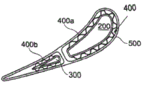
FIG. 7 shows a cross section through a rotor blade or stator vane airfoil, in this case also using an intermediate layer consisting of a honeycomb structure;
FIG. 7a illustrates a generalized flexible concept of a CMC airfoil having enhanced features;
FIG. 8 shows a cross section through a rotor blade or stator vane airfoil, in this case also using at least one intermediate layer consisting of a honeycomb structure, wherein the at least one intermediate layer is embedded integrally or quasi-integrally in a ceramic mat, which fills the space between the spar and the outer shell;
FIG. 9 shows another airfoil embodiment, largely corresponding to the previous FIGS. 7 and 8, in which the space between the flow-applying shell and the associated spar is bridged by regularly or irregularly distributed heights or contact points;
9a-b illustrate cords of various configurations;
FIG. 10 shows another airfoil embodiment, corresponding largely to the previous FIGS. 7 and 8, in which the space between the flow-applying outer shell and the associated spar is bridged by regularly or irregularly distributed heights, with at least one intermediate layer being integrally or quasi-integrally embedded in ceramic, which fills the space between the spar(s) and the outer shell;
FIGS. 10a-b illustrate various configurations of rope or spacer modules;
FIG. 11 shows another embodiment provided with two reinforcing inserts at LE and TE, respectively;
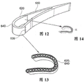
FIG. 12 illustrates the positioned insert in connection with the airfoil;
FIG. 13 shows the internal structure of a LE insert comprising a structured or controlled porous architecture, which allows for a strong and very efficient cooling of the insert;
fig. 14 shows the internal structure of a LE insert comprising a specially structured or controlled porous architecture, which allows a strong and very efficient cooling of the insert.
Detailed Description
Fig. 1 shows a partial longitudinal cross-section through an embodiment of a multi-ply CMC provided as a sandwich system. Basically, example CMC materials may be designed with individualized fiber structures according to operational requirements. A certain percentage of the fibers exhibit different diameters, which are intended to carry the mechanical loads (in case of larger diameters) within the CMC section of the hot gas path portion mainly during operation. The outermost panels 101a,101b of the sandwich system (100,101a, b, 110.) are composed of one or more plies, wherein at least one of the panels 101 possesses an integral or quasi-integral lubricious protective coating 100 having a strong contact with the panel's adjacent ceramic structure. In many applications (but not exclusively) it is preferred that the fibers of the first panel 101a have the same composition and/or material as the fibers of the second panel 101b disposed on the opposite side. The fibers of the first and second panels may be impregnated with the same or different materials, and it may be provided that only a portion of the circumference of the fibers is impregnated, wherein the impregnated side is designed to vary with installation, e.g., the impregnated side of the fibers is the side that is joined to the first layer 101a or the second layer 101 b.
The mentioned layers may consist of a laminate structure, so that a suitable bond between the individual intermediate layers (different textile sheet layers) is achieved. Further, the layer may be formed by a plurality of sandwich structures.
The intermediate ceramic mat 110 between the faceplates, which is similarly constructed of a 2D/3D woven structure with finer fibers, serves to secure the ceramic matrix to the entire fibrous substructure and deflect the local forces of the mechanical load to the ceramic matrix. As shown in fig. 1, the fibers of the articles 111,112,113, the intermediate ceramic mat 110 may be woven differently using the same or different materials such that the contact surfaces within the ceramic mat and on each side of the panel include both the first fibrous material and the second fibrous material. Representing a rectangular or quasi-rectangular weave according to the architecture of the article 111, an inclined or quasi-inclined or non-rectangular angled weave according to the architecture of the article 113; the weave represents a sinusoidal or quasi-sinusoidal, interdigitated weave, depending on the architecture of the article 112. Any stacking order of the different woven fibers (111,112,113, etc.) within the thickness of the sandwich arrangement is also possible.
Fig. 2 shows the outer surfaces of fibers 111a and 111b within ceramic mat 110 based on woven sections 111. The outer surfaces of the fibers 111a,111b are equally exposed on both sides of the three-dimensional structure, such that the contact surface on each comprises both the first and second material of the fibers. Fig. 3 shows a cross-sectional view of the woven fabric as shown in fig. 2 along the line 3-3. In this field, the single fiber or several fibers 111a,111b comprise regularly or irregularly arranged cords in the circumferential direction, or punctiform particles attached to the fibers 120, for maximizing the friction with each other (111a,111b) and within the entire structure of the ceramic mat 110.
Fig. 4 shows various textile architectures (a-e) of a sandwich structure, wherein fig. 5(a, b) shows an exemplary overall combination of cooling holes in the textile (through-gap and/or convective and/or impingement cooling): the textile fabric with the integrally bonded pore structure 150 is woven for use in hot areas where film cooling must be performed. It may be in the form of a single cooling hole or a row of cooling holes also extending over a wider area.
Fig. 6 shows an intermediate layer, denoted as a flexible layer, which will compensate for the CTE (coefficient of thermal expansion) mismatch between the metal core and the ceramic shell of the hot gas path component. The intermediate layer may be made of a 3D structured metal mesh (not shown in fig. 6) or as a corrugated metal or ceramic structure, e.g. honeycomb-like (see fig. a-c).
Fig. 7 to 10 show a section through a rotor blade or stator vane airfoil. The interior of the airfoil is provided with a vertically oriented and modular spar (made of one or several modules) which divides the interior into two individualized parts, namely spar 1 (item 200) and spar 2 (item 300). It may also be made of more than 2 spar modules.
Fig. 7 shows an additional use of the intermediate layer 400, the intermediate layer 400 being composed of, for example, a honeycomb structure. The flexible intermediate layer 400 is constructed of a material that is resistant to heat and oxidation, and can compensate for the CTE (coefficient of thermal expansion) mismatch between the ceramic/CMC constructed surrounding and flow imposed outer shell 500 and the metal spars 200, 300. The intermediate layers 400a (associated with spar 1) and 400b (associated with spar 2) may include the ability to absorb any impact in the event of a foreign object impact and avoid complete disassembly of the damaged CMC shell 500 or other liner system. This intermediate layer may also act as a spacer. This 3D intermediate layer structure may be made of a metal mesh of a 3D structure, or in the form of a corrugated metal structure, exhibiting a honeycomb-like or any similar texture.
FIG. 7a shows a CMC segment. The reinforced 2D woven inorganic textile sheet(s) may be wrapped around a central metal, polymer or ceramic 3D body, which serves as a mold. This mold may represent a turbine airfoil or inner/outer platform profile, or other hot gas path component, and may also include a local cooling air hole pattern (external film cooling). The final CMC body may then be positioned around a central metal spar (see fig. 7, articles 200,300) to allow for proper, precise positioning, mechanical support, and, if desired, cooling of the CMC airfoil shell.
Fig. 8 shows an additional use of the intermediate layer 400, the intermediate layer 400 being composed of a honeycomb structure, for example. The flexible intermediate layer 400 is constructed of a material that is resistant to heat and oxidation, and can compensate for the CTE (coefficient of thermal expansion) mismatch between the ceramic/CMC constructed surrounding and flow imposed outer shell 500 and the metal spars 200, 300. The intermediate layers 400a (associated with spar 1), 400b (associated with spar 2) may include the ability to absorb any impact in the event of a foreign object impact and avoid complete disassembly of the damaged CMC shell 500 or other liner system. This 3D intermediate layer structure may be made of a metal mesh of a 3D structure, or in the form of a corrugated metal structure, exhibiting a honeycomb-like or any similar texture. Furthermore, the intermediate layers 400a,400b are integrally or quasi-integrally embedded in a ceramic felt 600, which fills the space between the spar(s) and the outer shell. The core of the at least one intermediate space (not shown) may be filled with ceramic felt having different/varying compositions and consistencies as desired.
FIG. 9 illustrates another airfoil embodiment, which largely corresponds to previous FIGS. 7 and 8. The space between the flow applying shell 500 and the spars 200,300 is bridged by regularly or irregularly distributed elevations 210,310, which are equipped with differently configured ropes/spaced points, i.e. rounded 220 and/or T-shaped 230 ropes, whereby such an arrangement includes the ability to absorb any impact of foreign object impacts and can compensate for CTE (coefficient of thermal expansion) mismatches between the surrounding and flow applying shell 500 and the metal spars 200, 300.
FIG. 10 illustrates another airfoil embodiment, which largely corresponds to previous FIGS. 7 and 8. The space between the shell 500 and the spars 200,300 is bridged by regularly or irregularly distributed facades 210,310, which are equipped with differently configured ropes, i.e. circular 220 and/or T-shaped 230 ropes, whereby such an arrangement comprises the ability to absorb any impact of foreign object impacts and can compensate for CTE (coefficient of thermal expansion) mismatches between the surrounding and flow-exerting shell 500 and the metal spars 200, 300. Further, the intermediate layers 400a,400b are integrally or quasi-integrally embedded in a ceramic blanket 610, which fills the space between the spar(s) and the outer shell.
In another embodiment of the present invention according to fig. 11, the CMC shell 550 is fabricated as one single part, including the Suction Side (SS) and Pressure Side (PS) sections, while only the airfoil region is infiltrated with matrix material in a first step, dried and solidified (including a specific cooling hole pattern). After this partial fabrication is achieved, the CMC shell system is positioned around a central metal core (spar) 250 having a pre-positioned metal interlayer structure. The intermediate layer 450 is joined around the spar 250 (metal central core) by effective brazing, by high temperature cement bonding, mechanical fastening or a combination of the mentioned methods. The SS and PS CMC sections then wrap around fully prefabricated and pre-positioned inner Leading Edge (LE) and Trailing Edge (TE) sections or other thermally and thermo-mechanically loaded regions made of monolithic ceramic materials or a combination of monolithic and CMC skins. Such a reinforcing insert 620 may also include an inner and interconnected outer cooling system 630. The system may be designed or emergency cooling holes directly through the CAH. In the event of a shell breach, the emergency cooling holes open into the outer shell surface.
These holes may also be designed from the beginning to extend through the CAH, depending on the outer surface cooling requirements of the part.
Each of fig. 12,13 and 14 shows an additional porous body 640 as a natural continuation of the insert 620, positioned strictly in the region of the leading edge LE. The interior of the insert 620 may have a structured porous structure creating interconnected cooling cavities (see fig. 13 and 14), or an unsorted packing with ceramic material (e.g., felt), where the density and/or permeability may be varied as desired.
List of reference numerals
Sandwich arrangement 100,101a, 101b, 110, …
100 coating
101a ceramic first panel
101b ceramic second panel
110 ceramic felt
111 weave structure
External structure of 111a fiber
External structure of 111b fiber
112 weave structure
113 weave structure
120 fiber rope
150 weave textile fabric with integrated pore structure
200 wing beam
210 facade
220 round rope
230T-shaped rope
250 spar
300 spar
310 facade
400 middle layer
400a intermediate layer associated with the spar 200
400b intermediate layer associated with spar 300
450 middle layer
500 flow applied enclosure
550 CMC shell
600 ceramic felt
610 ceramic felt
620 reinforcing insert with controlled/machined porosity
630 cooling system
640 porous body
SS suction side
PS pressure side
LE leading edge
The TE trailing edge.
Claims (17)
1. A sandwich arrangement comprising at least two peripherally arranged ceramic faceplates (101a,101b) comprising respective CMC layers or CMC multilayers, and a ceramic mat (110) interposed between a first ceramic faceplate and a second ceramic faceplate (101a,101b), wherein the material of the first ceramic faceplate (101a) is identical to or different from the material of the second ceramic faceplate (101b), wherein the ceramic mat (110) is formed by a textile structure with regularly or quasi-regularly structured woven fibers, or the ceramic mat is made of irregular fibers intermixed with each other, wherein the fibers are made of at least one material and/or composition, wherein at least one bonding means is provided between the underside of the ceramic faceplates (101a,101b) and adjacent fibers of the ceramic mat (110); characterized in that the ceramic panels (101a,101b) have a fiber structure comprising a percentage of fibers, which exhibit a larger diameter and are intended to mainly carry mechanical loads, and thinner fibers for fixing the ceramic matrix of the ceramic panels to the entire fiber substructure and deflecting local forces of mechanical loads to the ceramic matrix.
2. The sandwich arrangement according to claim 1, characterised in that the ceramic panels and/or ceramic mats are constructed on a multi-walled structure, wherein the individual walls are spaced apart from each other, wherein the walls are mutually supported by support structures, wherein the resulting spaces between the support structures possess a weak, medium or strong permeability.
3. The sandwich arrangement according to claim 1 or 2, characterised in that each ceramic panel is composed of one or more plies, wherein the plies are made of the same material and composition, or differ among themselves.
4. The sandwich arrangement according to claim 1 or 2, wherein at least one surface of the ceramic panel comprises one or more coatings.
5. Sandwich arrangement according to claim 1 or 2, characterised in that the cladded CMC material is partially or completely infiltrated by a slurry technique or impregnated by CVD.
6. Sandwich arrangement according to claim 1 or 2, characterised in that the sandwich arrangement comprises at least one intermediate ceramic panel.
7. The sandwich arrangement according to claim 6, characterised in that the space between the first or second ceramic panel and the intermediate ceramic panel is filled with the same or different ceramic felt.
8. Sandwich arrangement according to claim 1 or 2, characterised in that at least one ceramic panel and/or ceramic felt is provided with cooling holes and/or cooling channels.
9. The sandwich arrangement according to claim 8, characterised in that the cooling holes or cooling channels are arranged between ceramic panels and/or ceramic felts.
10. Sandwich arrangement according to claim 9, characterised in that the flow of cooling medium through the ceramic panel and/or the ceramic felt is sealed off from the environment.
11. The sandwich arrangement according to claim 9, characterised in that a cooling medium flows partly or integrally through the ceramic panel and/or the ceramic felt.
12. The sandwich arrangement according to claim 1 or 2, wherein the sandwich arrangement is partially or integrally used in a hot gas path component of a turbomachine or gas turbine engine.
13. The sandwich arrangement according to claim 12, wherein the hot gas path component corresponds to an airfoil of a rotor blade or a stator vane, wherein the airfoil is composed of at least one flow applying shell and at least one lower structural element, wherein the flow applying shell is formed as a uniform or segmented structure.
14. The sandwich arrangement according to claim 13, characterised in that the airfoil under-structure element is constituted by at least one intermediate shell and/or at least one spar (200, 300).
15. The sandwich arrangement according to claim 13, characterised in that the flow-applied shell is further provided in the region of the leading edge and/or trailing edge with an insert, wherein the insert is made of monolithic ceramic material or a combination of monolithic ceramic material and CMC skin.
16. The sandwich arrangement according to claim 15, characterised in that the insert is provided with a structured internal cooling structure.
17. The sandwich arrangement according to claim 16, characterised in that the insert is provided with continuous and/or quasi-continuous cooling holes for use as an emergency cooling system.
Applications Claiming Priority (3)
| Application Number | Priority Date | Filing Date | Title |
|---|---|---|---|
| EP15162104.2 | 2015-03-31 | ||
| EP15162104.2A EP3075531B1 (en) | 2015-03-31 | 2015-03-31 | Sandwich arrangement with ceramic panels and ceramic felts |
| PCT/IB2016/051851 WO2016157127A1 (en) | 2015-03-31 | 2016-03-31 | Sandwich arrangement with ceramic panels and ceramic felts |
Publications (2)
| Publication Number | Publication Date |
|---|---|
| CN107667007A CN107667007A (en) | 2018-02-06 |
| CN107667007B true CN107667007B (en) | 2020-07-07 |
Family
ID=52807680
Family Applications (1)
| Application Number | Title | Priority Date | Filing Date |
|---|---|---|---|
| CN201680033201.9A Active CN107667007B (en) | 2015-03-31 | 2016-03-31 | Sandwich arrangement with ceramic faceplates and ceramic felt |
Country Status (4)
| Country | Link |
|---|---|
| US (1) | US20180065337A1 (en) |
| EP (1) | EP3075531B1 (en) |
| CN (1) | CN107667007B (en) |
| WO (1) | WO2016157127A1 (en) |
Families Citing this family (22)
| Publication number | Priority date | Publication date | Assignee | Title |
|---|---|---|---|---|
| EP3115199A1 (en) * | 2015-07-10 | 2017-01-11 | General Electric Technology GmbH | Manufacturing of single or multiple panels |
| DE102015215298A1 (en) * | 2015-08-11 | 2017-02-16 | Siemens Aktiengesellschaft | CMC component with stacked layers |
| US10767487B2 (en) | 2016-11-17 | 2020-09-08 | Raytheon Technologies Corporation | Airfoil with panel having flow guide |
| US10260363B2 (en) | 2016-12-08 | 2019-04-16 | General Electric Company | Additive manufactured seal for insert compartmentalization |
| US10428533B2 (en) * | 2017-05-19 | 2019-10-01 | Natalie A. Magnusson | Wall panel system |
| US10508810B2 (en) * | 2017-09-19 | 2019-12-17 | Hexcel Corporation | Thermal panel with a corrugated ceramic composite sheet having unequal ridge widths |
| US11802486B2 (en) * | 2017-11-13 | 2023-10-31 | General Electric Company | CMC component and fabrication using mechanical joints |
| US10487672B2 (en) * | 2017-11-20 | 2019-11-26 | Rolls-Royce Corporation | Airfoil for a gas turbine engine having insulating materials |
| KR102389756B1 (en) * | 2017-12-01 | 2022-04-22 | 지멘스 에너지, 인코포레이티드 | Brazed in Heat Transfer Feature for Cooled Turbine Components |
| US11002139B2 (en) * | 2017-12-12 | 2021-05-11 | Hamilton Sundstrand Corporation | Cooled polymer component |
| GB2573137B (en) * | 2018-04-25 | 2020-09-23 | Rolls Royce Plc | CMC aerofoil |
| US11015467B2 (en) * | 2018-07-06 | 2021-05-25 | Raytheon Technologies Corporation | Porous space fillers for ceramic matrix composites |
| FR3085373B1 (en) * | 2018-08-29 | 2021-09-24 | Safran Nacelles | COMPOSITE PART WITH SMOOTH EXTERNAL FACE AND ITS MANUFACTURING PROCESS |
| US10724387B2 (en) * | 2018-11-08 | 2020-07-28 | Raytheon Technologies Corporation | Continuation of a shear tube through a vane platform for structural support |
| EP3683406B1 (en) * | 2019-01-18 | 2023-11-29 | Ansaldo Energia Switzerland AG | Abradable hybrid material, particularly for seal elements in gas turbines, and manufacturing method thereof |
| US11060409B2 (en) * | 2019-05-13 | 2021-07-13 | Rolls-Royce Plc | Ceramic matrix composite aerofoil with impact reinforcements |
| US11365635B2 (en) * | 2019-05-17 | 2022-06-21 | Raytheon Technologies Corporation | CMC component with integral cooling channels and method of manufacture |
| NL2024045B1 (en) * | 2019-10-18 | 2021-06-22 | Viridi Holding B V | FRAME FOR A LIQUID-FLOWABLE 3D TEXTILE AND COMPOSITION OF SUCH FRAME AND 3D TEXTILE |
| US20230135034A1 (en) * | 2020-04-28 | 2023-05-04 | Lm Wind Power A/S | An interlayer, a spar cap and a wind turbine blade |
| US11421538B2 (en) * | 2020-05-12 | 2022-08-23 | Rolls-Royce Corporation | Composite aerofoils |
| US11512601B2 (en) * | 2020-05-18 | 2022-11-29 | Raytheon Technologies Corporation | Airfoil vane with coated jumper tube |
| US11506083B2 (en) | 2020-06-03 | 2022-11-22 | Rolls-Royce Corporalion | Composite liners for turbofan engines |
Family Cites Families (12)
| Publication number | Priority date | Publication date | Assignee | Title |
|---|---|---|---|---|
| FR2732336B1 (en) * | 1995-03-29 | 1997-06-20 | Aerospatiale | PROCESS FOR DEVELOPING A LIGHT SIC STRUCTURE, OF THE SANDWICH TYPE WITH A HONEYCOMB CORE, AND STRUCTURE THUS OBTAINED |
| DE19636223C2 (en) * | 1996-09-06 | 1999-07-08 | Deutsch Zentr Luft & Raumfahrt | Method for the permanent connection of at least two structural components to form a molded body |
| US6984277B2 (en) * | 2003-07-31 | 2006-01-10 | Siemens Westinghouse Power Corporation | Bond enhancement for thermally insulated ceramic matrix composite materials |
| US7153464B2 (en) * | 2003-12-01 | 2006-12-26 | General Electric Company | Method of making porous ceramic matrix composites |
| US8182905B2 (en) * | 2006-01-20 | 2012-05-22 | United Technologies Corporation | Ceramic matrix laminates |
| EP1953342A1 (en) | 2007-02-01 | 2008-08-06 | Siemens Aktiengesellschaft | Turbine blade |
| GB2451796B (en) | 2007-08-16 | 2010-03-10 | Rolls Royce Plc | Laminated structure with an interlayer |
| EP2571686A1 (en) * | 2010-05-17 | 2013-03-27 | General Electric Company | Ceramic matrix composite structures, components formed therewith, and methods of producing |
| WO2014022344A1 (en) | 2012-07-31 | 2014-02-06 | General Electric Company | Cmc core cowl and method of fabricating |
| US9527262B2 (en) | 2012-09-28 | 2016-12-27 | General Electric Company | Layered arrangement, hot-gas path component, and process of producing a layered arrangement |
| US9664052B2 (en) * | 2012-10-03 | 2017-05-30 | General Electric Company | Turbine component, turbine blade, and turbine component fabrication process |
| EP2781691A1 (en) | 2013-03-19 | 2014-09-24 | Alstom Technology Ltd | Method for reconditioning a hot gas path part of a gas turbine |
-
2015
- 2015-03-31 EP EP15162104.2A patent/EP3075531B1/en active Active
-
2016
- 2016-03-31 CN CN201680033201.9A patent/CN107667007B/en active Active
- 2016-03-31 WO PCT/IB2016/051851 patent/WO2016157127A1/en active Application Filing
- 2016-03-31 US US15/563,824 patent/US20180065337A1/en not_active Abandoned
Also Published As
| Publication number | Publication date |
|---|---|
| US20180065337A1 (en) | 2018-03-08 |
| CN107667007A (en) | 2018-02-06 |
| WO2016157127A1 (en) | 2016-10-06 |
| EP3075531B1 (en) | 2024-03-20 |
| EP3075531A1 (en) | 2016-10-05 |
Similar Documents
| Publication | Publication Date | Title |
|---|---|---|
| CN107667007B (en) | Sandwich arrangement with ceramic faceplates and ceramic felt | |
| CN106640206B (en) | Manufacture of single or multiple panels | |
| EP1919846B1 (en) | Refractory component with ceramic matrix composite skeleton | |
| US7153096B2 (en) | Stacked laminate CMC turbine vane | |
| US7435058B2 (en) | Ceramic matrix composite vane with chordwise stiffener | |
| EP1429917B1 (en) | Ceramic matrix composite structure having integral cooling passages and method of manufacture | |
| CN107250485B (en) | Ceramic matrix composite turbine machine component with the ad hoc surface characteristics for keeping thermal barrier coating | |
| EP1367223B1 (en) | Ceramic matrix composite gas turbine vane | |
| US10132170B2 (en) | Systems and method for a composite blade with fillet transition | |
| CN103206265B (en) | For the grid adhesive layer that the continuous fiber of barrier of environment coat system is strengthened | |
| US7217088B2 (en) | Cooling fluid preheating system for an airfoil in a turbine engine | |
| US20170328223A1 (en) | Hybrid ceramic matrix composite materials | |
| US20070140835A1 (en) | Cooling systems for stacked laminate cmc vane | |
| EP3440316A1 (en) | Ceramic component for combustion turbine engines | |
| WO2020209847A1 (en) | Three dimensional ceramic matrix composite wall structures fabricated by using pin weaving techniques | |
| EP3572625B1 (en) | Joint for a shroud platform in ceramic | |
| WO2021067979A1 (en) | Composite layer system having an additively manufactured substrate and a thermal protection system | |
| CN115680783A (en) | Fragile airfoil with shape memory alloy |
Legal Events
| Date | Code | Title | Description |
|---|---|---|---|
| PB01 | Publication | ||
| PB01 | Publication | ||
| SE01 | Entry into force of request for substantive examination | ||
| SE01 | Entry into force of request for substantive examination | ||
| GR01 | Patent grant | ||
| GR01 | Patent grant |