CN107563243B - One-dimensional bar code identification method - Google Patents
One-dimensional bar code identification method Download PDFInfo
- Publication number
- CN107563243B CN107563243B CN201710148676.9A CN201710148676A CN107563243B CN 107563243 B CN107563243 B CN 107563243B CN 201710148676 A CN201710148676 A CN 201710148676A CN 107563243 B CN107563243 B CN 107563243B
- Authority
- CN
- China
- Prior art keywords
- waveform
- bar code
- line
- value
- point
- Prior art date
- Legal status (The legal status is an assumption and is not a legal conclusion. Google has not performed a legal analysis and makes no representation as to the accuracy of the status listed.)
- Active
Links
Images


Landscapes
- Optical Transform (AREA)
- Geophysics And Detection Of Objects (AREA)
Abstract
本发明提供一种一维条码识别方法,包括步骤:通过反射式光电传感器对一维条码进行采样,获得多个采样信号;绘制一维条码的一条码波形;在条码波形中获得与一维条码的起点和终点对应的一起点波点和一终点波点;在所述条码波形中定位与所述白双线对应的一第一波形段;计算各所述线条组对应的一第二波段的宽度,获得各所述线条组的线宽;根据所述线宽和所述条码图判断各所述第二波段对应的线条组的种类;根据所述第二波段对应的线条组的种类获得一二进制码;将所述二进制码与一预设的编码表作比对,获得一识别结果。本发明的一种一维条码识别方法,具有可靠性强、识别率高并可适用于小体积的反射式光电传感器的优点。
The invention provides a one-dimensional barcode identification method, which comprises the steps of: sampling the one-dimensional barcode by a reflective photoelectric sensor to obtain a plurality of sampling signals; drawing the barcode waveform of the one-dimensional barcode; obtaining and the one-dimensional barcode in the barcode waveform A first wave point and an end point wave point corresponding to the starting point and end point of the bar code waveform; locate a first waveform segment corresponding to the white double line in the barcode waveform; Width of each line group is obtained; according to the line width and the barcode image, the type of the line group corresponding to each of the second wavebands is determined; according to the type of the line group corresponding to the second waveband, a Binary code; compare the binary code with a preset coding table to obtain an identification result. The one-dimensional bar code identification method of the present invention has the advantages of strong reliability, high identification rate and suitable for small-volume reflective photoelectric sensors.
Description
技术领域technical field
本发明涉及条码识别领域,尤其涉及一种一维条码识别方法。The invention relates to the field of barcode identification, in particular to a one-dimensional barcode identification method.
背景技术Background technique
一维条码是目前市场的常见条码型式,常用于各类生产、生活用品上,用于记录产品信息便于分辨和追溯,目前一维码的识别方式主要采用激光或图像识别原理,手持式条码枪是主要产品,其基本原理是根据黑白条码对光的反射率的不同来分辨黑白及其宽度。One-dimensional barcode is a common barcode type in the current market. It is often used in various production and daily necessities. It is used to record product information for easy identification and traceability. At present, the identification method of one-dimensional code mainly adopts the principle of laser or image recognition. Hand-held barcode gun It is the main product, and its basic principle is to distinguish black and white and its width according to the difference in the reflectivity of black and white barcodes to light.
目前,常见的条码识别方案有:At present, the common barcode identification schemes are:
1、发射电路恒流源供电,红色谱系LED(黑色反射率敏感),接近条码端小孔出光,对侧小孔收光,光敏二极管或三极管接收并转换光信号,后级电路转换并放大信号,经A/D采集用于分析黑白及条码宽度。1. The transmitter circuit is powered by a constant current source, the red color LED (black reflectivity is sensitive), the small hole near the barcode end emits light, the opposite side small hole receives light, the photodiode or triode receives and converts the light signal, and the post-stage circuit converts and amplifies the signal , collected by A/D for analysis of black and white and bar code width.
2、发射电路恒流源供电,红色谱系LED(黑色反射率敏感),接近条码端有一些简单光学件提供光学聚焦限制光点大小,保证光信号强度,对侧增加简单光学件提供光学聚焦汇聚反射信号,增强接收信号强度减少干扰,再由光敏二极管或三极管接收并转换光信号,后级电路转换并放大信号,经A/D采集用于分析黑白及条码宽度。2. The transmitter circuit is powered by constant current source, red color LED (sensitive to black reflectivity), and some simple optics near the barcode end to provide optical focusing to limit the spot size to ensure optical signal strength, and simple optics are added to the opposite side to provide optical focusing and convergence Reflect the signal, enhance the received signal strength and reduce interference, and then receive and convert the optical signal by the photodiode or triode, and the post-stage circuit converts and amplifies the signal, and is collected by A/D for analysis of black and white and barcode width.
现有设计方案存在以下问题:The existing design scheme has the following problems:
1、空间占用依然较大,由于需要确保一定的发射角和反射角,LED及光敏接收管需要拉开足够的距离用于安装,如存在光学件则整体尺寸还需要进一步增大。1. The space occupation is still large. Due to the need to ensure a certain emission angle and reflection angle, the LED and photosensitive receiving tube need to be separated enough for installation. If there are optical components, the overall size needs to be further increased.
2、接收电路复杂,多级转换放大,元器件数量增多,导致电路结构变大,电路可靠性降低,可生产性及可服务性降低。2. The receiving circuit is complex, multi-stage conversion and amplification, and the number of components increases, resulting in a larger circuit structure, reduced circuit reliability, and reduced productivity and serviceability.
3、由于LED和接收管安装存在角度要求,对机械设计、生产、检验、组装提出了更高的要求,不利于批量生产。3. Due to the angle requirements for the installation of LEDs and receiving tubes, higher requirements are put forward for mechanical design, production, inspection and assembly, which is not conducive to mass production.
可见,由于目前市场上一维码识别产品普遍向激光、图像识别方向发展,其使用条件要求一定的距离,无法满足小型化使用需求,而传统条码识别基本原理的光反射设计方案中电子元器件数量较多且结构复杂,无法保证批量生产的可靠性和稳定性,同时也达不到最大限度缩小体积的要求。It can be seen that because the current market of one-dimensional code recognition products generally develops in the direction of laser and image recognition, its use conditions require a certain distance, which cannot meet the needs of miniaturization. The quantity is large and the structure is complex, which cannot guarantee the reliability and stability of mass production, and also cannot meet the requirements of minimizing the volume.
发明内容SUMMARY OF THE INVENTION
针对上述现有技术中的不足,本发明提供一种一维条码识别方法,具有可靠性强、识别率高并可适用于小体积的反射式光电传感器的优点。In view of the above-mentioned deficiencies in the prior art, the present invention provides a one-dimensional barcode identification method, which has the advantages of strong reliability, high identification rate, and is applicable to small-volume reflective photoelectric sensors.
为了实现上述目的,本发明提供一种一维条码识别方法,包括步骤:In order to achieve the above purpose, the present invention provides a one-dimensional barcode identification method, comprising the steps of:
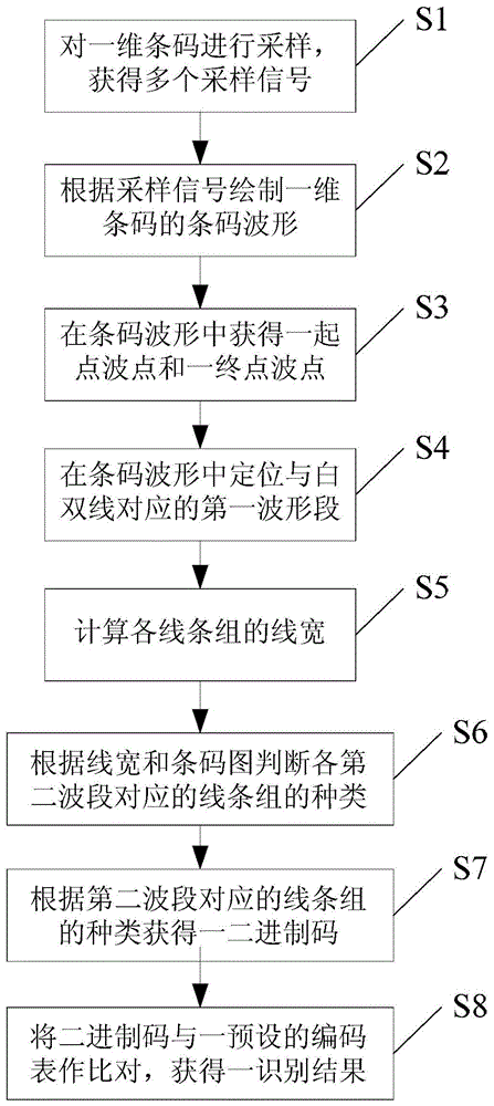
S1:对一一维条码进行采样,获得多个采样信号;S1: Sampling a one-dimensional barcode to obtain multiple sampling signals;
S2:根据所述采样信号绘制所述一维条码的一条码波形;S2: Draw a barcode waveform of the one-dimensional barcode according to the sampling signal;
S3:处理所述条码波形,在所述条码波形中获得与所述一维条码的起点和终点对应的一起点波点和一终点波点;S3: Process the barcode waveform, and obtain a first wave point and an end point wave point corresponding to the starting point and the ending point of the one-dimensional barcode in the barcode waveform;
S4:所述一维条码包括多个线条组,所述线条组包括白双线、黑双线、白单线和黑单线,根据所述起点波点、所述终点波点和所述条码波形在所述条码波形中定位与所述白双线对应的一第一波形段;S4: The one-dimensional barcode includes a plurality of line groups, and the line group includes a white double line, a black double line, a white single line and a black single line. According to the starting point wave point, the end point wave point and the barcode waveform Locate a first waveform segment corresponding to the white double line in the barcode waveform;
S5:通过所述条码波形去除所述第一波形段的图形,计算各所述线条组对应的一第二波形段的宽度,获得各所述线条组的线宽;S5: Remove the graph of the first waveform segment from the barcode waveform, calculate the width of a second waveform segment corresponding to each of the line groups, and obtain the line width of each of the line groups;
S6:根据所述线宽和所述条码波形判断各所述第二波形段对应的线条组的种类;S6: Determine the type of the line group corresponding to each of the second waveform segments according to the line width and the barcode waveform;
S7:根据所述第二波形段对应的线条组的种类获得一二进制码;S7: Obtain a binary code according to the type of the line group corresponding to the second waveform segment;
S8:将所述二进制码与一预设的编码表作比对,获得一识别结果。S8: Compare the binary code with a preset coding table to obtain an identification result.
优选地,所述S1步骤中:通过一反射式光电传感器对所述一维条码进行采样。Preferably, in the step S1: sampling the one-dimensional barcode by a reflective photoelectric sensor.
优选地,所述反射式光电传感器包括一壳体、一发光二极管和一三极管,所述壳体形成并列的两安装腔,两所述安装腔分别在所述反射式光电传感器的一工作面形成一工作窗口,所述发光二极管和所述三极管分别设置于一所述安装腔内。Preferably, the reflective photoelectric sensor includes a housing, a light emitting diode and a triode, the housing forms two parallel mounting cavities, and the two mounting cavities are respectively formed on a working surface of the reflective photoelectric sensor A working window, the light emitting diode and the triode are respectively arranged in the installation cavity.
优选地,所述反射式光电传感器固定于一固定组件且所述反射式光电传感器的所述工作面通过所述扫描缝外露。Preferably, the reflective photoelectric sensor is fixed on a fixing component, and the working surface of the reflective photoelectric sensor is exposed through the scanning slit.
优选地,通过将固定有所述反射式光电传感器的所述固定组件放置于所述一维条码上单向移动获得所述采样信号。Preferably, the sampling signal is obtained by placing the fixed component fixed with the reflective photoelectric sensor on the one-dimensional barcode and moving in one direction.
优选地,所述S3步骤进一步包括步骤:Preferably, the S3 step further comprises the steps:
获取所述条码波形的多个第一最大值和多个第一最小值,对所述第一最大值和所述第一最小值求均值,获得一第一均值;obtaining a plurality of first maximum values and a plurality of first minimum values of the barcode waveform, and averaging the first maximum values and the first minimum values to obtain a first average value;
根据所述第一均值在所述条码波形中添加一第一中线;adding a first center line to the barcode waveform according to the first mean value;
根据所述第一中线与所述条码波形的交点,确定所述起点波点和所述终点波点。The starting point wave point and the end point wave point are determined according to the intersection of the first center line and the barcode waveform.
优选地,所述S4步骤进一步包括步骤:Preferably, the S4 step further comprises the steps:
在所述起点波点和所述终点波点间获取一第二最大值和一第二最小值,计算所述第二最大值和所述第二最小值的均值,获得一第二均值;Obtain a second maximum value and a second minimum value between the starting point wave point and the end point wave point, calculate the average value of the second maximum value and the second minimum value, and obtain a second average value;
根据所述第二均值在所述条码波形中添加一第二中线;adding a second center line to the barcode waveform according to the second mean value;
根据所述条码波形和所述第二中线定位所述第一波形段,所述第一波形段位于所述起点波点和所述终点波点之间,所述第一波形段上的点值大于所述第二均值,且所述第一波形段与所述第二中线的两交点的间距大于一预设值。The first waveform segment is positioned according to the barcode waveform and the second center line, the first waveform segment is located between the start point and the end point, and the point value on the first waveform segment is greater than the second average value, and the distance between the two intersection points of the first waveform segment and the second center line is greater than a predetermined value.
优选地,所述S5步骤进一步包括步骤:Preferably, the S5 step further comprises the steps:
在所述条码波形去除所述第一波形段的图形上获取多个第三最大值和多个第三最小值,计算所述第三最大值和所述第三最小值的均值,获得一第三均值;Obtain a plurality of third maximum values and a plurality of third minimum values on the graph of the barcode waveform with the first waveform segment removed, calculate the average value of the third maximum value and the third minimum value, and obtain a first three means;
根据所述第三均值在所述条码波形中添加一第三中线,所述第三中线将所述条码波形分割为多个所述第二波形段;A third center line is added to the barcode waveform according to the third average value, and the third center line divides the barcode waveform into a plurality of the second waveform segments;
根据所述条码波形与所述第三中线的交点,计算所述第二波形段对应所述线条组的线宽。According to the intersection of the barcode waveform and the third center line, the line width of the second waveform segment corresponding to the line group is calculated.
优选地,所述S6步骤中:Preferably, in the step S6:
当当前所述第二波形段上的点值小于所述第三均值,且所述第二波形段与所述第三中线的两交点的间距大于所述预设值时,当前所述第二波形段所对应的线条组为黑双线;When the current point value on the second waveform segment is smaller than the third average value, and the distance between the two intersection points of the second waveform segment and the third center line is greater than the preset value, the current second waveform segment is The line group corresponding to the waveform segment is a black double line;
当当前所述第二波形段上的点值小于所述第三均值,且所述第二波形段与所述第三中线的两交点的间距小于所述预设值时,当前所述第二波形段所对应的线条组为黑单线;When the current point value on the second waveform segment is less than the third average value, and the distance between the two intersection points of the second waveform segment and the third center line is less than the preset value, the current second waveform segment is less than the predetermined value. The line group corresponding to the waveform segment is a black single line;
当当前所述第二波形段上的点值大于所述第三均值,且所述第二波形段与所述第三中线的两交点的间距小于所述预设值时,当前所述第二波形段所对应的线条组为白单线。When the current point value on the second waveform segment is greater than the third average value, and the distance between the two intersection points of the second waveform segment and the third center line is smaller than the preset value, the current second waveform segment The line group corresponding to the waveform segment is a white single line.
优选地,所述S7步骤中:根据所述条码波形上的所述第一波形段和所述第二波形段所对应的线条组的排列顺序和种类,并根据各所述线条组的种类所对应的一预设码值,排列组合生成所述二进制码。Preferably, in the step S7: according to the arrangement order and type of the line groups corresponding to the first waveform segment and the second waveform segment on the barcode waveform, and according to the type of each line group A corresponding preset code value is permuted and combined to generate the binary code.
本发明由于采用了以上技术方案,使其具有以下有益效果:The present invention has the following beneficial effects due to the adoption of the above technical solutions:
本发明的一种一维条码识别方法具有可靠性强、识别率高并可适用于小体积的反射式光电传感器的优点。The one-dimensional bar code identification method of the present invention has the advantages of strong reliability, high identification rate, and is applicable to small-volume reflective photoelectric sensors.
附图说明Description of drawings
图1为本发明实施例的一维条码识别方法的流程图;1 is a flowchart of a one-dimensional barcode identification method according to an embodiment of the present invention;
图2为本发明实施例的一维条码识别装置的结构示意图;2 is a schematic structural diagram of a one-dimensional barcode identification device according to an embodiment of the present invention;
图3为本发明实施例的一维条码识别方法的添加第一中线时的条码波形图;3 is a barcode waveform diagram when a first center line is added in a one-dimensional barcode identification method according to an embodiment of the present invention;
图4为本发明实施例的一维条码识别方法的添加第二中线时的条码波形图;4 is a barcode waveform diagram when a second center line is added in a one-dimensional barcode identification method according to an embodiment of the present invention;
图5为本发明实施例的一维条码识别方法的添加第三中线时的条码波形图;5 is a barcode waveform diagram when a third center line is added in a one-dimensional barcode identification method according to an embodiment of the present invention;
图6为本发明实施例的反射式光电传感器的结构示意图;6 is a schematic structural diagram of a reflective photoelectric sensor according to an embodiment of the present invention;
图7为本发明实施例的反射式光电传感器与信号处理电路板的连接电路图;7 is a connection circuit diagram of a reflective photoelectric sensor and a signal processing circuit board according to an embodiment of the present invention;
图8为本发明实施例的一维条码识别装置的工作状态图。FIG. 8 is a working state diagram of a one-dimensional barcode identification device according to an embodiment of the present invention.
具体实施方式Detailed ways
下面根据附图1~图8,给出本发明的较佳实施例,并予以详细描述,使能更好地理解本发明的功能、特点。Hereinafter, the preferred embodiments of the present invention are given and described in detail according to the accompanying
请参阅图1和图2,本发明实施的一种一维条码识别方法,包括步骤:Please refer to FIG. 1 and FIG. 2 , a one-dimensional barcode identification method implemented by the present invention includes the steps:
S1:通过一小型一维条码识别装置的反射式光电传感器对一一维条码进行采样,获得500个采样信号;S1: Sampling the one-dimensional barcode through a reflective photoelectric sensor of a small one-dimensional barcode identification device to obtain 500 sampling signals;
本实施例中,反射式光电传感器固定于一固定组件且反射式光电传感器的工作面通过扫描缝外露,通过将固定有反射式光电传感器的固定组件放置于一维条码上单向移动获得采样信号。In this embodiment, the reflective photoelectric sensor is fixed on a fixed component and the working surface of the reflective photoelectric sensor is exposed through the scanning slit, and the sampling signal is obtained by placing the fixed component fixed with the reflective photoelectric sensor on the one-dimensional barcode and moving in one direction .
S2:根据采样信号绘制一维条码的一条码波形。S2: Draw the barcode waveform of the one-dimensional barcode according to the sampling signal.
S3:处理条码波形,在条码波形中获得与一维条码的起点和终点对应的一起点波点和一终点波点。S3: Process the barcode waveform, and obtain a first wave point and an end point wave point corresponding to the starting point and the ending point of the one-dimensional barcode in the barcode waveform.
请参阅图1和图3,本实施例中,S3步骤进一步包括步骤:Please refer to FIG. 1 and FIG. 3. In this embodiment, step S3 further includes steps:
获取条码波形的多个第一最大值a1和多个第一最小值c1,对第一最大值a1和第一最小值c1求均值,获得一第一均值;Obtain a plurality of first maximum values a1 and a plurality of first minimum values c1 of the barcode waveform, and average the first maximum value a1 and the first minimum value c1 to obtain a first average value;
根据第一均值在条码波形中添加一第一中线b1;Add a first center line b1 to the barcode waveform according to the first mean value;
根据第一中线b1与条码波形的交点,确定起点波点和终点波点。According to the intersection of the first center line b1 and the barcode waveform, the starting point wave point and the end point wave point are determined.
S4:一维条码包括多个线条组,线条组包括白双线、黑双线、白单线和黑单线,根据起点波点、终点波点和条码波形在条码波形中定位与白双线对应的一第一波形段。S4: The one-dimensional barcode includes multiple line groups. The line group includes white double lines, black double lines, white single lines and black single lines. According to the starting point wave point, the end point wave point and the barcode waveform, locate the corresponding white double line in the barcode waveform. a first waveform segment.
请参阅图1和图4,本实施例中,S4步骤进一步包括步骤:Please refer to FIG. 1 and FIG. 4. In this embodiment, step S4 further includes steps:
在起点波点和终点波点间获取一第二最大值a2和一第二最小值c2,计算第二最大值a2和第二最小值c2的均值,获得一第二均值;Obtain a second maximum value a2 and a second minimum value c2 between the start point wave point and the end point wave point, calculate the mean value of the second maximum value a2 and the second minimum value c2, and obtain a second mean value;
根据第二均值在条码波形中添加一第二中线b2;Add a second center line b2 to the barcode waveform according to the second mean value;
根据条码波形和第二中线定位第一波形段,第一波形段位于起点波点和终点波点之间,第一波形段上的点值大于第二均值,且第一波形段与第二中线b2的两交点的间距大于一预设值,本实施例中,预设值为35个采样单位。The first waveform segment is located according to the barcode waveform and the second center line, the first waveform segment is located between the start point and the end point, the point value on the first waveform segment is greater than the second average value, and the first waveform segment and the second center line The distance between the two intersection points of b2 is greater than a preset value. In this embodiment, the preset value is 35 sampling units.
S5:通过条码波形去除第一波形段的图形,计算各线条组对应的一第二波形段的宽度,获得各线条组的线宽。S5: Remove the graph of the first waveform segment by the barcode waveform, calculate the width of a second waveform segment corresponding to each line group, and obtain the line width of each line group.
请参阅图1和图5,本实施例中,S5步骤进一步包括步骤:Please refer to FIG. 1 and FIG. 5. In this embodiment, step S5 further includes steps:
在条码波形去除第一波形段的图形上获取多个第三最大值a3和多个第三最小值c3,计算第三最大值a3和第三最小值c3的均值,获得一第三均值;Obtain a plurality of third maximum values a3 and a plurality of third minimum values c3 on the graph of the barcode waveform removing the first waveform segment, calculate the average value of the third maximum value a3 and the third minimum value c3, and obtain a third average value;
根据第三均值在条码波形中添加一第三中线b3,第三中线b3将条码波形分割为多个第二波形段;A third center line b3 is added to the barcode waveform according to the third average value, and the third center line b3 divides the barcode waveform into a plurality of second waveform segments;
根据条码波形与第三中线b3的交点,计算第二波形段对应线条组的线宽。According to the intersection of the barcode waveform and the third center line b3, the line width of the line group corresponding to the second waveform segment is calculated.
S6:根据线宽和条码波形判断各第二波形段对应的线条组的种类。S6: Determine the type of the line group corresponding to each second waveform segment according to the line width and the barcode waveform.
其中,当当前第二波形段上的点值小于第三均值,且第二波形段与第三中线b3的两交点的间距大于预设值时,当前第二波形段所对应的线条组为黑双线;Wherein, when the point value on the current second waveform segment is less than the third average value, and the distance between the two intersection points of the second waveform segment and the third center line b3 is greater than the preset value, the line group corresponding to the current second waveform segment is black double line;
当当前第二波形段上的点值小于第三均值,且第二波形段与第三中线b3的两交点的间距小于预设值时,当前第二波形段所对应的线条组为黑单线;When the point value on the current second waveform segment is less than the third average value, and the distance between the two intersection points of the second waveform segment and the third midline b3 is less than the preset value, the line group corresponding to the current second waveform segment is a black single line;
当当前第二波形段上的点值大于第三均值,且第二波形段与第三中线b3的两交点的间距小于预设值时,当前第二波形段所对应的线条组为白单线。When the point value on the current second waveform segment is greater than the third average value, and the distance between the two intersection points of the second waveform segment and the third center line b3 is smaller than the preset value, the line group corresponding to the current second waveform segment is a white single line.
S7:根据条码波形上的第一波形段和第二波形段所对应的线条组的排列顺序和种类,并根据各线条组的种类所对应的一预设码值,排列组合生成二进制码。S7: According to the arrangement order and type of the line groups corresponding to the first waveform segment and the second waveform segment on the barcode waveform, and according to a preset code value corresponding to the type of each line group, arrange and combine to generate a binary code.
S8:将二进制码与一预设的编码表作比对,获得一识别结果,本实施例中,识别结果为一4位数码值,编码表可根据需要进行调整。S8: Compare the binary code with a preset encoding table to obtain an identification result. In this embodiment, the identification result is a 4-digit digital value, and the encoding table can be adjusted as required.
本发明的一种一维条码识别方法,具有识别率高和适用于小型反射式光电传感器进行一维码识别的优点。The one-dimensional bar code identification method of the present invention has the advantages of high recognition rate and is suitable for a small reflective photoelectric sensor for one-dimensional code identification.
请参阅图2,本实施例的小型一维条码识别装置,包括一反射式光电传感器1、一固定组件2、一信号处理电路板(图中未示)和一电源(图中未示),固定组件2形成一扫描缝24,反射式光电传感器1固定于固定组件2且反射式光电传感器1的一工作面通过扫描缝24外露;反射式光电传感器1连接信号处理电路板和电源。Referring to FIG. 2, the small one-dimensional barcode identification device of this embodiment includes a reflective
固定组件2包括一第一固定件21、一第二固定件22和一安装座23,反射式光电传感器1固定于安装座23,第一固定件21和第二固定件22配合形成一固定空间25和扫描缝24,反射式光电传感器1通过安装座23固定于固定空间25内。The fixing
本实施例中,反射式光电传感器1固定于第一固定件21和第二固定件22之间,第一固定件21与第二固定件22间隔一固定间距形成扫描缝24。扫描缝24的宽度小于等于1mm。In this embodiment, the reflective
请参阅图6和图7,反射式光电传感器1包括一壳体11、一发光二极管D和一三极管Q,壳体11形成并列的两安装腔12,两安装腔12分别在工作面形成一工作窗口13,发光二极管D和三极管Q分别设置于一安装腔12内,发光二极管D的阳极和三极管Q的集电极连接电源;三极管Q的发射极连接反射式光电传感器1的一输出端。6 and 7, the reflective
信号处理电路板包括一主芯片(图中未示)、一限流电阻R1和一负载电阻R2,其中,主芯片连接反射式光电传感器1的输出端Output。限流电阻R1第一端连接发光二极管D的阴极,限流电阻R1的第二端接地或通过一开关接地。负载电阻R2的第一端连接三极管Q的发射极,负载电阻R2的第二端接地。The signal processing circuit board includes a main chip (not shown in the figure), a current limiting resistor R1 and a load resistor R2, wherein the main chip is connected to the output terminal Output of the reflective
本实施例中,主芯片型号为STM32F103R8T6,内置有12bit的A/D转换器,采样电压信号转换为数字量,从而可实现将连续的电压数字量构成检测条码波形,最后根据条码波形分辨黑白最终解析成条码值。信号处理电路板结构简单,可提高装置整体的可靠性和可生产性。In this embodiment, the model of the main chip is STM32F103R8T6, with a built-in 12-bit A/D converter, and the sampling voltage signal is converted into a digital quantity, so that the continuous voltage digital quantity can be formed into a detection barcode waveform, and finally black and white are distinguished according to the barcode waveform. Parse into barcode value. The signal processing circuit board has a simple structure and can improve the overall reliability and productivity of the device.
反射式光电传感器1结构简单、体积小,从而大幅度减小装置整体的体积。通过调制限流电阻R1实现对发光二极管D光源强度的调整。通过调制负载电阻R2阻值实现对输出信号强度的调整。The reflective
请参阅图8,使用本实施例的小型一维条码识别装置进行条码识别时,将小型一维条码识别装置置于条码载体3上方,条码载体3与装置的距离为0.4~0.8mm,条码载体3单向运动,反射式光电传感器1通过扫描缝24检测反馈信号变化,本实施例中,扫描缝24宽度为0.4mm±0.1mm,可识别条码单黑条宽度>0.5mm,根据扫描缝24黑白变化触发反射式光电传感器1输出电压信号变化,按35采样点/mm频率采样还原信号波形图,再根据算法识别单黑线、单白线、双黑线、双白线,最后解析成条码值。Referring to FIG. 8 , when the small one-dimensional barcode identification device of this embodiment is used for barcode identification, the small one-dimensional barcode identification device is placed above the
本实施例的小型一维条码识别装置体积尺寸非常小,可做到5mm*5mm*3mm的大小,可应用于小型手持设备,结构简单、成本低廉。The small one-dimensional barcode identification device of this embodiment is very small in size, and can achieve a size of 5mm*5mm*3mm, and can be applied to small handheld devices, with simple structure and low cost.
以上结合附图实施例对本发明进行了详细说明,本领域中普通技术人员可根据上述说明对本发明做出种种变化例。因而,实施例中的某些细节不应构成对本发明的限定,本发明将以所附权利要求书界定的范围作为本发明的保护范围。The present invention has been described in detail above with reference to the embodiments of the accompanying drawings, and those skilled in the art can make various modifications to the present invention according to the above description. Therefore, some details in the embodiments should not be construed to limit the present invention, and the present invention will take the scope defined by the appended claims as the protection scope of the present invention.
Claims (7)
Priority Applications (1)
| Application Number | Priority Date | Filing Date | Title |
|---|---|---|---|
| CN201710148676.9A CN107563243B (en) | 2017-03-14 | 2017-03-14 | One-dimensional bar code identification method |
Applications Claiming Priority (1)
| Application Number | Priority Date | Filing Date | Title |
|---|---|---|---|
| CN201710148676.9A CN107563243B (en) | 2017-03-14 | 2017-03-14 | One-dimensional bar code identification method |
Publications (2)
| Publication Number | Publication Date |
|---|---|
| CN107563243A CN107563243A (en) | 2018-01-09 |
| CN107563243B true CN107563243B (en) | 2020-11-10 |
Family
ID=60972855
Family Applications (1)
| Application Number | Title | Priority Date | Filing Date |
|---|---|---|---|
| CN201710148676.9A Active CN107563243B (en) | 2017-03-14 | 2017-03-14 | One-dimensional bar code identification method |
Country Status (1)
| Country | Link |
|---|---|
| CN (1) | CN107563243B (en) |
Families Citing this family (2)
| Publication number | Priority date | Publication date | Assignee | Title |
|---|---|---|---|---|
| CN110720910B (en) * | 2019-10-12 | 2022-03-29 | 宁波工程学院 | Muscle movement unit searching method based on correlation |
| CN112819121B (en) * | 2021-01-28 | 2022-06-28 | 丁松林 | Curve code generation method, curve code identification method, terminal device and readable storage medium |
Citations (4)
| Publication number | Priority date | Publication date | Assignee | Title |
|---|---|---|---|---|
| US20020056754A1 (en) * | 2000-11-10 | 2002-05-16 | Maurizio Bianchi | Device and method for reading coded information, and device for detecting a luminous signal diffused by a support containing coded information |
| CN101877057A (en) * | 2009-12-02 | 2010-11-03 | 中兴通讯股份有限公司 | A barcode recognition method and device |
| CN104217189A (en) * | 2014-08-25 | 2014-12-17 | 苏州百慧华业精密仪器有限公司 | Self-learning identification method of barcode used for test strip |
| CN105844200A (en) * | 2016-03-17 | 2016-08-10 | 杭州晟元数据安全技术股份有限公司 | Method of determining bar code type |
Family Cites Families (2)
| Publication number | Priority date | Publication date | Assignee | Title |
|---|---|---|---|---|
| US7777172B2 (en) * | 2007-06-01 | 2010-08-17 | Fairchild Semiconductor Corporation | Methods for reducing cross talk in optical sensors |
| CN104732183B (en) * | 2015-03-20 | 2017-06-13 | 杭州晟元数据安全技术股份有限公司 | A kind of bar code recognition methods based on the analysis of image sampling line half-tone information |
-
2017
- 2017-03-14 CN CN201710148676.9A patent/CN107563243B/en active Active
Patent Citations (4)
| Publication number | Priority date | Publication date | Assignee | Title |
|---|---|---|---|---|
| US20020056754A1 (en) * | 2000-11-10 | 2002-05-16 | Maurizio Bianchi | Device and method for reading coded information, and device for detecting a luminous signal diffused by a support containing coded information |
| CN101877057A (en) * | 2009-12-02 | 2010-11-03 | 中兴通讯股份有限公司 | A barcode recognition method and device |
| CN104217189A (en) * | 2014-08-25 | 2014-12-17 | 苏州百慧华业精密仪器有限公司 | Self-learning identification method of barcode used for test strip |
| CN105844200A (en) * | 2016-03-17 | 2016-08-10 | 杭州晟元数据安全技术股份有限公司 | Method of determining bar code type |
Non-Patent Citations (1)
| Title |
|---|
| 线阵CCD对条形码的测量与识别实验;杨飒等;《实验室科学》;20111228;第14卷(第6期);第110-112页 * |
Also Published As
| Publication number | Publication date |
|---|---|
| CN107563243A (en) | 2018-01-09 |
Similar Documents
| Publication | Publication Date | Title |
|---|---|---|
| US9507051B2 (en) | Photoelectric switch for detection of an object and method for operating the same | |
| JP2018119986A5 (en) | ||
| CN107563243B (en) | One-dimensional bar code identification method | |
| CN211786109U (en) | A laser time-of-flight lidar | |
| US20070029514A1 (en) | Method and system for detecting the position of an edge of a web | |
| JP2574780B2 (en) | Reflective photoelectric switch | |
| CN115561826B (en) | Proximity detection circuit and proximity sensor | |
| CN103377360A (en) | Bar code and scanning device corresponding to bar code | |
| CN103307988B (en) | A kind of light stability system for linear measuring system | |
| CN203705864U (en) | Photoelectric switch for object detection | |
| CN111010230A (en) | High-efficiency solar blind ultraviolet light transmitting and receiving system | |
| CN205666813U (en) | Retro -reflection formula photoelectric switch | |
| US20120287084A1 (en) | Wireless Communicational Optical Positioning Determining Device | |
| CN108983206B (en) | Laser distance measuring device and positioning system with communication function | |
| US12540847B2 (en) | Photoplethysmography front-end receiver | |
| CN109738882B (en) | A High-precision Adjustable Distance Measuring Circuit Based on Infrared Pair Tube | |
| US9016579B2 (en) | Apparatus for and method of electro-optically reading a target in the presence of ambient light | |
| EP3015958A1 (en) | Light sensor array device | |
| US9804000B2 (en) | Optical sensor array apparatus | |
| CN206584366U (en) | Small-sized bar code identifying device | |
| CN211786101U (en) | Infrared range sensor | |
| CN202374268U (en) | OLT (Optical Line Terminal) module optical power detection circuit | |
| CN219038819U (en) | Photoelectric sensor for detecting front and back surfaces of glass slide | |
| CN210982728U (en) | A laser receiver circuit | |
| CN221376686U (en) | Correlation photoelectric sensor with optical code |
Legal Events
| Date | Code | Title | Description |
|---|---|---|---|
| PB01 | Publication | ||
| PB01 | Publication | ||
| SE01 | Entry into force of request for substantive examination | ||
| SE01 | Entry into force of request for substantive examination | ||
| CB02 | Change of applicant information |
Address after: 201201 Shanghai City, Pudong New Area Ruiqinglu No. 526 Applicant after: Shanghai Aopu biomedical Co., Ltd Address before: 201201 Shanghai City, Pudong New Area Ruiqinglu No. 526 Applicant before: Shanghai Upper Bio-tech Pharma Co., Ltd. |
|
| CB02 | Change of applicant information | ||
| GR01 | Patent grant | ||
| GR01 | Patent grant |