CN107546552B - Plug connector and combination thereof - Google Patents
Plug connector and combination thereof Download PDFInfo
- Publication number
- CN107546552B CN107546552B CN201610482281.8A CN201610482281A CN107546552B CN 107546552 B CN107546552 B CN 107546552B CN 201610482281 A CN201610482281 A CN 201610482281A CN 107546552 B CN107546552 B CN 107546552B
- Authority
- CN
- China
- Prior art keywords
- locking
- button
- protruding
- insulating body
- plug connector
- Prior art date
- Legal status (The legal status is an assumption and is not a legal conclusion. Google has not performed a legal analysis and makes no representation as to the accuracy of the status listed.)
- Active
Links
Images


Landscapes
- Details Of Connecting Devices For Male And Female Coupling (AREA)
Abstract
本发明公开了一种插头连接器及其组合,其包括插头连接器与插座连接器,插头连接器包括第一绝缘本体、锁扣件以及绝缘外壳,插座连接器包括壳体,锁扣件包括可受压回弹的锁扣臂,锁扣臂设有凸伸出第一绝缘本体的突出部以及卡锁部,绝缘外壳对应突出部的位置设有按钮,壳体对应卡锁部的位置设有限位槽,插接配对时卡锁部限位于限位槽,按压按钮可实现该按钮带动锁扣臂弹性变形,以使卡锁部脱离限位槽的限位,锁扣件、按钮及限位槽的配合能将电连接器组合的插接或断开分为若干个阶段,有利于避免电源端子的瞬间放电、提高电连接器的安全性。
The invention discloses a plug connector and a combination thereof. The plug connector includes a plug connector and a socket connector. The plug connector includes a first insulating body, a locking member and an insulating shell. The socket connector includes a housing, and the locking member includes A locking arm that can rebound under pressure, the locking arm is provided with a protrusion protruding out of the first insulating body and a locking portion, the insulating shell is provided with a button at the position corresponding to the protrusion, and the housing is provided with a position corresponding to the locking portion. Limiting slot, the locking part is limited to the limiting slot when mating, pressing the button can realize the button to drive the locking arm to elastically deform, so that the locking part can be separated from the limit of the limiting slot, the locking piece, the button and the limit The matching of the slot can divide the plugging or disconnecting of the electrical connector assembly into several stages, which is beneficial to avoid the instantaneous discharge of the power terminal and improve the safety of the electrical connector.
Description
【技术领域】【Technical field】
本发明有关一种插头连接器及其组合,尤其是指一种在插拔时较为安全的插头连接器及其组合。The present invention relates to a plug connector and a combination thereof, in particular to a plug connector and a combination thereof that are relatively safe during plugging and unplugging.
【背景技术】【Background technique】
现有技术请参照中国实用新型第CN204144588U号专利公告的一种电连接器组合,其包括相互配合的第一连接器与第二连接器,所述第一连接器包括第一绝缘本体及固持于第一绝缘本体的第一端子,第二连接器包括第二绝缘本体及固持于第二绝缘本体的第二端子,第一、第二端子均包括五根端子,该五根端子分别为位于中间的侦测端子以及位于侦测端子两侧的电源端子,在对接方向上,五根第一端子平齐设置,五根第二端子也平齐设置,当第一、第二连接器插拔时,第一、第二电源端子与第一、第二侦测端子同时进行接触导通或断开,可能会造成电源端子的瞬间放电,存在安全隐患,影响电连接器的使用寿命。For the prior art, please refer to an electrical connector combination disclosed in Chinese Utility Model No. CN204144588U, which includes a first connector and a second connector that cooperate with each other, and the first connector includes a first insulating body and a The first terminal of the first insulating body, the second connector includes a second insulating body and a second terminal fixed on the second insulating body, the first and second terminals each include five terminals, and the five terminals are located in the middle. The detection terminals and the power terminals located on both sides of the detection terminals, in the docking direction, the five first terminals are arranged flush, and the five second terminals are also arranged flush, when the first and second connectors are inserted and pulled out , the first and second power terminals and the first and second detection terminals are connected or disconnected at the same time, which may cause instantaneous discharge of the power terminals, posing a safety hazard and affecting the service life of the electrical connector.
因此,确有必要提供一种新的插头连接器及其组合,以克服上述缺陷。Therefore, it is necessary to provide a new plug connector and its combination to overcome the above-mentioned defects.
【发明内容】[Content of the invention]
本发明的目的在于提供一种插头连接器及其组合,其插接与断开的过程具有若干个阶段,能够避免电源端子的瞬间放电、提高电连接器的安全性。The purpose of the present invention is to provide a plug connector and its combination, the process of plugging and disconnecting has several stages, which can avoid the instantaneous discharge of the power terminal and improve the safety of the electrical connector.
本发明的目的通过以下技术方案一来实现:一种插头连接器,其包括第一绝缘本体、固持于所述第一绝缘本体的第一端子、固定在所述第一绝缘本体上的锁扣件以及组装于所述第一绝缘本体外侧的绝缘外壳,所述锁扣件包括可受压回弹的锁扣臂,所述锁扣臂设有凸伸出所述第一绝缘本体的突出部,所述绝缘外壳对应所述突出部的位置设有可按压所述突出部的按钮,所述锁扣臂设有与所述突出部同向凸伸的卡锁部,按压所述按钮可实现按压所述突出部以进一步带动所述锁扣臂沿背离所述凸伸方向弹性变形,以使所述卡锁部沿所述凸伸方向发生偏移。The object of the present invention is achieved through the following technical solution: a plug connector, which includes a first insulating body, a first terminal fixed on the first insulating body, and a lock fixed on the first insulating body and an insulating shell assembled on the outside of the first insulating body, the locking piece includes a locking arm that can be pressed and rebounded, and the locking arm is provided with a protrusion protruding from the first insulating body , the insulating shell is provided with a button that can press the protrusion at the position corresponding to the protrusion, and the locking arm is provided with a locking portion that protrudes in the same direction as the protrusion, and pressing the button can realize Pressing the protruding portion further drives the locking arm to elastically deform in a direction away from the protruding direction, so that the locking portion is displaced along the protruding direction.
进一步地,所述第一绝缘本体包括一对沿一对接方向延伸的第一承载部以及位于所述两第一承载部之间的第二承载部,所述锁扣臂包括沿所述对接方向延伸且设于所述第二承载部上方的一对第一锁扣臂,所述第一锁扣臂设有凸伸出所述第二承载部的第一突出部以及与所述第一突出部同向凸伸的第一卡锁部。Further, the first insulating body includes a pair of first bearing portions extending along a butting direction and a second bearing portion located between the two first bearing portions, and the locking arm includes a pair of first bearing portions along the butting direction A pair of first locking arms extending and arranged above the second bearing portion, the first locking arms are provided with a first protrusion protruding out of the second bearing portion and a first protrusion extending from the second bearing portion. The first locking portion protrudes in the same direction.
进一步地,所述按钮包括对应所述第一突出部的位置设置并可沿所述第一突出部凸伸方向按压的第一按钮,按压所述第一按钮可实现该第一按钮与所述第一突出部接触并进一步带动所述第一锁扣臂沿所述凸伸方向弹性变形,以使所述第一卡锁部沿所述凸伸方向发生偏移。Further, the button includes a first button that is set corresponding to the position of the first protrusion and can be pressed along the protruding direction of the first protrusion. Pressing the first button can realize the first button and the first button. The first protruding portion contacts and further drives the first locking arm to elastically deform along the protruding direction, so that the first locking portion is displaced along the protruding direction.
进一步地,所述锁扣件包括与所述第一锁扣臂同向延伸的一对第二锁扣臂,所述两第二锁扣臂分别固定在两第一承载部的外侧,所述第二锁扣臂延伸设有第二卡锁部,所述第二卡锁部的延伸方向与所述第一卡锁部的延伸方向垂直,所述第二锁扣臂设有与所述第二卡锁部同向延伸的第二突出部,所述按钮包括对应所述第二突出部的位置设置并可沿所述第二突出部延伸方向按压的第二按钮,按压所述第二按钮可实现该第二按钮与所述第二突出部接触并进一步带动所述第二锁扣臂弹性变形,以使所述第二卡锁部沿所述延伸方向发生偏移。Further, the locking piece includes a pair of second locking arms extending in the same direction as the first locking arms, the two second locking arms are respectively fixed on the outer sides of the two first bearing parts, the The second locking arm extends with a second locking portion, the extending direction of the second locking portion is perpendicular to the extending direction of the first locking portion, and the second locking arm is provided with the first locking portion. The two latching portions extend in the same direction, and the button includes a second button that is set corresponding to the position of the second protruding portion and can be pressed along the extending direction of the second protruding portion. Pressing the second button The second button can be brought into contact with the second protruding portion and further drive the second locking arm to elastically deform, so that the second locking portion is displaced along the extending direction.
进一步地,所述第一端子包括第一侦测端子,所述第一侦测端子设有第一侦测部,所述第一侦测部的后方设有凸伸出所述第一绝缘本体的凸起部, 所述凸起部位于所述一对锁扣臂之间,按压所述按钮可使该按钮与所述凸起部接触并进一步带动所述第一侦测部发生弹性形变。Further, the first terminal includes a first detection terminal, the first detection terminal is provided with a first detection portion, and the rear of the first detection portion is provided with a protruding out of the first insulating body The protruding part is located between the pair of locking arms, and pressing the button can make the button contact the protruding part and further drive the first detection part to elastically deform.
本发明的目的还通过以下技术方案二来实现:一种插头连接器组合,定义有一对接方向,其包括可插接配对的插头连接器与插座连接器,所述插头连接器包括第一绝缘本体、固持于所述第一绝缘本体的第一端子、固定于所述第一绝缘本体的锁扣件以及组装于所述第一绝缘本体外侧的绝缘外壳,所述插座连接器包括第二绝缘本体、固持于所述第二绝缘本体的第二端子以及罩设在所述第二绝缘本体外侧的壳体,所述锁扣件包括可受压回弹的锁扣臂,所述锁扣臂设有凸伸出所述第一绝缘本体的突出部以及与所述突出部同向凸伸的卡锁部,所述绝缘外壳对应所述突出部的位置设有可按压所述突出部的按钮,所述壳体对应所述卡锁部的位置设有限位槽,当所述电连接器组合插接配对时所述卡锁部限位于所述限位槽,按压所述按钮可实现该按钮与所述突出部接触并进一步带动所述锁扣臂沿所述凸伸方向弹性变形,以使所述卡锁部脱离所述限位槽的限位。The object of the present invention is also achieved through the following technical solution: a plug-connector combination, which defines a mating direction, which includes a plug connector and a socket connector that can be plugged and mated, and the plug connector includes a first insulating body , a first terminal fixed on the first insulating body, a locking piece fixed on the first insulating body, and an insulating shell assembled on the outside of the first insulating body, the socket connector includes a second insulating body , a second terminal held on the second insulating body and a casing covering the outside of the second insulating body, the locking member includes a locking arm that can be pressed and rebounded, and the locking arm is provided with There are protruding parts protruding out of the first insulating body and a locking part protruding in the same direction as the protruding parts, and the insulating housing is provided with a button that can press the protruding part at the position corresponding to the protruding part, The housing is provided with a limit slot at the position corresponding to the locking portion, and the locking portion is limited to the limit slot when the electrical connectors are assembled and mated, and pressing the button can realize the button and the locking portion. The protruding portion contacts and further drives the locking arm to elastically deform along the protruding direction, so that the locking portion is released from the limiting position of the limiting groove.
进一步地,所述第一绝缘本体包括一对沿所述对接方向延伸的第一承载部以及位于所述两第一承载部之间的第二承载部,所述锁扣臂包括沿所述对接方向延伸且设于所述第二承载部上方的一对第一锁扣臂,所述第一锁扣臂设有凸伸出所述第二承载部的第一突出部以及与所述第一突出部同向凸伸的第一卡锁部,所所述限位槽包括对应所述第一卡锁部设置的第一限位槽。Further, the first insulating body includes a pair of first bearing portions extending along the butting direction and a second bearing portion located between the two first bearing portions, and the locking arm includes a pair of first bearing portions extending along the butting direction. A pair of first locking arms extending in the direction and arranged above the second bearing portion, the first locking arms are provided with a first protrusion protruding out of the second bearing portion and a The protruding portion is a first locking portion protruding in the same direction, and the limiting groove includes a first limiting groove corresponding to the first locking portion.
进一步地,所述按钮包括对应所述第一突出部的位置设置并可沿所述第一突出部凸伸方向按压的第一按钮,按压所述第一按钮可实现该第一按钮与所述第一突出部接触并进一步带动所述第一锁扣臂沿所述凸伸方向弹性变形,以使所述第一卡锁部脱离所述第一限位槽的限位。Further, the button includes a first button that is set corresponding to the position of the first protrusion and can be pressed along the protruding direction of the first protrusion. Pressing the first button can realize the first button and the first button. The first protruding portion contacts and further drives the first locking arm to elastically deform along the protruding direction, so that the first locking portion is released from the limiting position of the first limiting groove.
进一步地,所述锁扣件包括与所述第一锁扣臂同向延伸的一对第二锁扣臂,所述两第二锁扣臂分别固定在两第一承载部的外侧,所述第二锁扣臂延伸设有第二卡锁部,所述壳体对应所述第二卡锁部设有第二限位槽,所述第二锁扣臂设有与所述第二卡锁部同向延伸的第二突出部,所述按钮包括对应所述第二突出部的位置设置并可沿所述第二突出部延伸方向按压的第二按钮,按压所述第二按钮可实现该第二按钮与所述第二突出部接触并进一步带动所述第二锁扣臂弹性变形,以使所述第二卡锁部脱离所述第二限位槽的限位。Further, the locking piece includes a pair of second locking arms extending in the same direction as the first locking arms, the two second locking arms are respectively fixed on the outer sides of the two first bearing parts, the The second locking arm is extended with a second locking portion, the housing is provided with a second limiting groove corresponding to the second locking portion, and the second locking arm is provided with the second locking portion. A second protrusion extending in the same direction, the button includes a second button corresponding to the position of the second protrusion and can be pressed along the extending direction of the second protrusion. Pressing the second button can realize the The second button is in contact with the second protruding portion and further drives the second locking arm to elastically deform, so that the second locking portion is released from the limiting position of the second limiting groove.
进一步地,所述第一端子包括第一侦测端子与第一电源端子,所述第二端子包括分别与所述第一侦测端子、第一电源端子对接的第二侦测端子、第二电源端子,所述第二限位槽的长度大于所述第一限位槽的长度,当将配接后的插头连接器从所述插座连接器中拔出时,按压所述第一按钮使所述第一按钮带动所述凸起部、第一突出部下压,以使所述第一、第二侦测部断开连接且所述第一卡锁部脱离所述第一限位槽的限位,此时所述第一、第二电源端子仍保持连接且所述第二卡锁部仍限位于所述第二限位槽,进一步使所述插头连接器沿着所述第二限位槽向远离所述插座连接器的位置移动至所述第二限位槽的边缘,最后,按压所述第二按钮后使所述第二卡锁部受压发生偏移从而脱离所述第二限位槽的限位,此时可将插头连接器沿着所述对接方向完全拔出所述插座连接器。Further, the first terminal includes a first detection terminal and a first power terminal, and the second terminal includes a second detection terminal and a second detection terminal that are respectively connected with the first detection terminal and the first power terminal. The power terminal, the length of the second limit slot is greater than the length of the first limit slot, when the plug connector after mating is pulled out from the socket connector, pressing the first button to make The first button drives the protruding part and the first protruding part to press down, so that the first and second detecting parts are disconnected and the first locking part is separated from the first limiting groove. At this time, the first and second power terminals are still connected and the second locking portion is still limited to the second limit groove, and the plug connector is further allowed to move along the second limit. The position slot moves away from the socket connector to the edge of the second position limit slot, and finally, after pressing the second button, the second locking portion is pressed and displaced so as to be separated from the first locking portion. At this time, the plug connector can be completely pulled out of the socket connector along the docking direction.
与现有技术相比,本发明具有如下有益效果:本发明插头连接器及其组合中锁扣件与按钮的配合能够将所述电连接器组合的插接或断开分为若干个阶段,即侦测端子与电源端子呈不同的时序对接或断开,避免了电源端子的瞬间放电,提高了电连接器的安全指数和使用寿命,此外,第一按钮控制侦测端子开合的设计更进一步增加了电连接器的安全性且操作方便。Compared with the prior art, the present invention has the following beneficial effects: the cooperation of the locking member and the button in the plug connector and the combination thereof of the present invention can divide the plugging or disconnecting of the electrical connector combination into several stages, That is, the detection terminal and the power terminal are connected or disconnected in different timings, which avoids the instantaneous discharge of the power terminal and improves the safety index and service life of the electrical connector. In addition, the design of the first button to control the opening and closing of the detection terminal is more convenient. The safety of the electrical connector is further increased and the operation is convenient.
【附图说明】【Description of drawings】
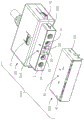
图1是本发明插头连接器的立体图。FIG. 1 is a perspective view of the plug connector of the present invention.
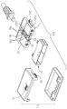
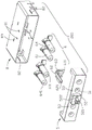
图2是图1所示插头连接器的立体分解图。FIG. 2 is an exploded perspective view of the plug connector shown in FIG. 1 .
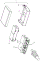
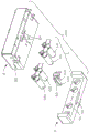
图3是图2所示插头连接器另一角度的立体分解图。FIG. 3 is an exploded perspective view of the plug connector shown in FIG. 2 from another angle.
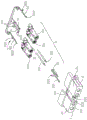
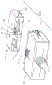
图4是本发明插头连接器的部分立体分解图。Figure 4 is a partially exploded perspective view of the plug connector of the present invention.
图5是本发明插座连接器的立体图。5 is a perspective view of the socket connector of the present invention.
图6是图5所示插座连接器的立体分解图。FIG. 6 is an exploded perspective view of the receptacle connector shown in FIG. 5 .
图7是图6所示插座连接器另一角度的立体分解图。FIG. 7 is an exploded perspective view of the receptacle connector shown in FIG. 6 from another angle.
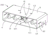
图8是本发明插头连接器组合的立体图。8 is a perspective view of the plug connector assembly of the present invention.
图9是图8所示插头连接器组合另一角度的立体图。FIG. 9 is a perspective view of the plug connector assembly shown in FIG. 8 from another angle.
图10是本发明插头连接器组合对接状态的立体图。FIG. 10 is a perspective view of the plug-connector combination of the present invention in a butt joint state.
图11是本发明插头连接器组合沿图10中的A-A线的剖视图。11 is a cross-sectional view of the plug connector assembly of the present invention taken along line A-A in FIG. 10 .
图12是本发明插头连接器组合沿图10中的B-B线的剖视图。FIG. 12 is a cross-sectional view of the plug connector assembly of the present invention taken along the line B-B in FIG. 10 .
图13是本发明插头连接器组合另一对接状态的立体图。13 is a perspective view of another mating state of the plug-connector assembly of the present invention.
图14是本发明插头连接器组合沿图13中的C-C线的剖视图。FIG. 14 is a cross-sectional view of the plug connector assembly of the present invention taken along line C-C in FIG. 13 .
图15是本发明插头连接器组合沿图13中的D-D线的剖视图。15 is a cross-sectional view of the plug connector assembly of the present invention taken along the line D-D in FIG. 13 .
图16是图14所示插头连接器组合按下第一按钮时的剖视图。FIG. 16 is a cross-sectional view of the plug connector assembly shown in FIG. 14 when the first button is pressed.
图17是图12所示插头连接器组合按下第二按钮时的剖视图。FIG. 17 is a cross-sectional view of the plug connector assembly shown in FIG. 12 when the second button is pressed.
图18是本发明插头连接器组合第一端子的立体分解图与第二端子的立体图。18 is an exploded perspective view of the first terminal and a perspective view of the second terminal of the plug connector of the present invention.
图19是本发明插头连接器组合第一端子与第二端子对接时的立体图。19 is a perspective view of the plug connector of the present invention when the first terminal and the second terminal are butted together.
【主要组件符号说明】【Description of main component symbols】
如下具体实施方式将结合上述附图进一步说明本发明。The following specific embodiments will further illustrate the present invention in conjunction with the above drawings.
【具体实施方式】【Detailed ways】
以下,将结合图1至图19介绍本发明插头连接器及其组合的具体实施方式。Hereinafter, specific embodiments of the plug connector and the combination thereof of the present invention will be introduced with reference to FIGS. 1 to 19 .
请参照图1至图9所示,本发明揭示了一种插头连接器组合1000,其包括相互对接的插头连接器100与插座连接器200。定义所述插头连接器100与所述插座连接器200的相互插接方向为对接方向。Referring to FIG. 1 to FIG. 9 , the present invention discloses a
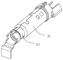
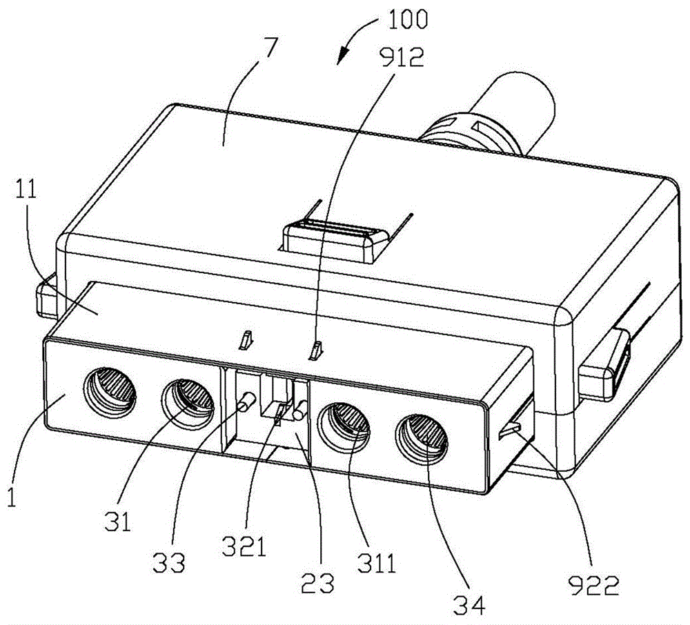
如图1至图7所示,所述插头连接器100设有位于所述对接方向前端的第一对接面1且包括第一绝缘本体2、固持于所述第一绝缘本体2的第一端子3、固定在所述第一绝缘本体2上的锁扣件9以及包覆所述第一绝缘本体2的绝缘外壳7,所述绝缘外壳7设有按钮;所述插座连接器200设有第二对接面4且包括第二绝缘本体5、固持于所述第二绝缘本体5的第二端子6以及罩设在所述第二绝缘本体5外侧的壳体8,所述壳体8与所述第二端子6之间形成对接空间10,在本实施例中,所述壳体8的材质为不锈钢。所述第一对接面1与第二对接面4分别为所述插头连接器100与插座连接器200相互对接时最先与对方进行对接的部分,所述第一端子3包括第一电源端子31及第一侦测端子32,所述第二端子6包括分别与第一电源端子31及第一侦测端子32相配合的第二电源端子61及第二侦测端子62,所述第一、第二电源端子31、61分别设有沿对接方向延伸并相互对接的第一、第二接触部311、611,所述第一、第二侦测端子32、62分别设有相互接触以达成侦测功能的第一、第二侦测部321、621,所述第一接触部311比所述第一侦测部321更靠近所述第一对接面1,所述第二接触部611比所述第二侦测部621更靠近所述第二对接面4。As shown in FIG. 1 to FIG. 7 , the
重点参阅图4,所述第一绝缘本体2包括一对沿所述对接方向延伸的第一承载部21以及位于所述两第一承载部21之间的第二承载部22,所述两第一承载部21较第二承载部22更靠近所述第一对接面1进而在所述第二承载部22的前端形成一凹陷23(标号见图1),每一第一承载部21设有贯穿其前端的收容槽211,所述第二承载部22设有贯穿其前端并与所述凹陷23相贯通的凹槽221以及位于凹槽221一侧并与所述凹槽221相贯通的插槽222(标号见图3)。所述第一接触部311分别收容在所述收容槽211内,所述第一侦测部321收容在所述插槽222内并凸伸入所述凹槽23内,即所述第一电源端子31设于所述第一承载部21上,所述第一侦测端子32设于所述第二承载部22上。4 , the first insulating body 2 includes a pair of
重点参阅图6与图11,所述第二绝缘本体5包括若干开槽51以及一向前凸伸的凸台52,所述第二接触部611分别向前凸伸出所述开槽51,当所述插头连接器100与插座连接器200相互对接时,所述凸台52收容在所述插头连接器100的凹陷23内,且所述凸台25的前端设有一对向前凸伸并收容在所述凹槽23内的支撑部521,所述第二侦测部621固持在所述两支撑部521之间以供所述第一侦测部321正向或反向接触进而达成侦测功能。6 and 11 , the second
所述第一端子3包括一对第一信号端子33,第二端子6包括一对与所述第一信号端子33配合以传输信号的第二信号端子63,所述凹陷23设有一对位于所述凹槽23外部的用于收容所述第一信号端子32的第一信号端子槽231,所述凸台52设有一对位于所述两支撑部521外的用于收容所述第二信号端子63的第二信号端子槽522,所述第一、第二信号端子33、63分别设有收容在所述第一、第二信号端子槽321、522内的第一、第二对接部331、631,参阅图16,所述第一对接部331比所述第一接触部311更靠近所述第一对接面1,所述第二侦测部621比所述第二对接部631更靠近所述第二对接面4,所述插头连接器100与插座连接器200相互对接时,所述第一、第二信号端子33、63早于所述第一、第二侦测端子32、62进行接触并且晚于所述第一、第二电源端子31、61进行接触。The first terminal 3 includes a pair of
所述第一端子3还包括一对第一接地端子34、所述第二端子6还包括一对第二接地端子64,所述第一、第二接地端子34、64分别设有第一、第二接地部341、641。在本实施例中,于所述对接方向上,所述第一接地部341比所述第一接触部311更靠近所述第一对接面1,所述第二接地部641与所述第二接触部611平齐,因此,在对接时所述第一、第二接地端子34、64是所有端子中最早进行接触导通的。The first terminal 3 further includes a pair of
如图8至图9所示,所述第一端子3与第二端子6各包括可相互对接的七根端子,所述第一端子3的七根端子分别为位于中间的第一侦测端子32、位于所述第一侦测端子32两侧的一对第一信号端子33、位于所述第一信号端子33外侧的一对第一电源端子31以及位于最外侧的一对第一接地端子34;所述第二端子6中各端子的排布与所述第一端子3的排布相对应。As shown in FIG. 8 to FIG. 9 , each of the first terminal 3 and the
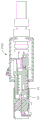
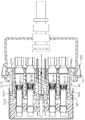
如图18与图19所示,所述第一电源端子31的第一接触部311包括套筒3111及设于套筒3111内的环状弹性夹持元件3112,所述夹持元件3112包括若干个沿所述对接方向延伸的且呈圆周排列的弹片3113,所述弹片3113设有沿所述圆周的圆心方向凸伸出的对接点3114。参阅图12,所述套筒3111包括向其内部凸出的限位部3115,所述夹持元件3112在所述对接方向上限位于所述限位部3115。所述插头连接器100与插座连接器200对接时,所述第二接触部611插入所述夹持元件3112内,所述对接点3114与所述第二接触部611通过多点接触实现电流的多通道导通,从而使该插头连接器组合1000在进行大电流传输的同时温升较小。As shown in FIGS. 18 and 19 , the
参阅图11与图13,所述第一侦测端子32在所述第一侦测部321的后方凸设有凸伸出所述第二承载部22的凸起部322,所述按钮包括对应所述凸起部322的位置设置的且可沿所述凸起部322延伸方向按压的第一按钮71,按压所述第一按钮71可使该第一按钮71与所述凸起部322接触并进一步带动所述第一侦测部321沿垂直于所述对接方向发生弹性形变,从而可断开所述第一侦测端子32与所述第二侦测端子62之间的电性连接。Referring to FIG. 11 and FIG. 13 , the
如图1至图7所示,所述固定在所述第一绝缘本体2上的锁扣件9包括可受压回弹的锁扣臂,在本实施例中,所述锁扣臂包括沿所述对接方向延伸且设于所述第二承载部22上方的一对第一锁扣臂91,所述凸起部322位于所述一对第一锁扣臂91之间,所述第一锁扣臂91设有凸伸出所述第二承载部22且与所述凸起部322同向延伸的第一突出部911以及与所述第一突出部911同向凸伸的第一卡锁部912。如此,所述第一突出部911的位置也对应于所述第一按钮71设置,且所述第一按钮71可按压所述第一突出部911。所述壳体8对应所述第一卡锁部912的位置设有与所述第一锁扣臂91同向延伸的第一限位槽81,当所述插头连接器组合1000插接配对时所述第一卡锁部912限位于所述第一限位槽81,按压所述第一按钮71可实现该第一按钮在与所述凸起部322接触的同时也与所述第一突出部911接触并进一步带动所述第一锁扣臂91沿背离所述凸伸方向弹性变形,以使所述第一卡锁部912沿所述凸伸方向发生偏移,以使所述第一卡锁部912脱离所述第一限位槽81的限位。As shown in FIG. 1 to FIG. 7 , the locking
如图2至图4所示,所述锁扣件包括与所述第一锁扣臂91同向延伸的一对第二锁扣臂92,所述两第二锁扣臂92分别固定在两第一承载部21的外侧,所述第二锁扣臂92延伸设有第二卡锁部922,所述壳体8对应所述第二卡锁部922设有与所述第一限位槽81平行的第二限位槽82,当所述插头连接器组合1000插接配对时所述第二卡锁部922限位于所述第二限位槽82,在本实施例中,所述第二卡锁部922的延伸方向与所述第一卡锁部912的延伸方向垂直,在所述对接方向上,所述第二限位槽82的长度大于所述第一限位槽81的长度。As shown in FIG. 2 to FIG. 4 , the locking member includes a pair of second locking
所述第二锁扣臂92设有与所述第二卡锁部922同向延伸的第二突出部921,所述绝缘外壳7上的按钮还包括对应所述第二突出部921的位置设置并可沿所述第二突出部921延伸方向按压的第二按钮72。参阅图12、图16及图17,当所述插头连接器组合1000插接配对时所述第二卡锁部922限位于所述第二限位槽82,按压所述第二按钮72可实现该第二按钮72与所述第二突出部921接触并进一步带动所述第二锁扣臂92弹性变形,以使所述第二卡锁部922沿所述延伸方向发生偏移从而脱离所述第二限位槽82的限位。The
参阅图10至图17,该等图示为所述插头连接器100与插座连接器200的不同对接过程,以下针对上述对接过程做详细说明。图10至图12为所述插头连接器组合1000完全对接的状态,此时所述第一、第二卡锁部912、922分别限位于所述第一、第二限位槽81、82中;参阅图12与图13,当将配接后的插头连接器100从所述插座连接器200中拔出时,按压所述第一按钮71,所述凸起部322与所述第一突出部911同时被所述第一按钮71带动而下压,此时所述第一侦测部321与所述第二侦测部621断开连接而第一、第二电源端子31、61仍然保持电性接触,所述第一卡锁部912脱离所述第一限位槽81的限位,而此时所述第二卡锁部922仍限位于所述第二限位槽82,由于所述第二限位槽82的长度大于所述第一限位槽81的长度,因此插头连接器100可进一步沿着所述第二限位槽82的延伸方向(即对接方向)朝着远离所述插座连接器200的位置移动至所述第二限位槽82靠近所述第二对接面4的边缘(如图14所示的状态);如图14至17所示,按压所述第二按钮72后可使所述第二卡锁部922受压发生偏移从而脱离所述第二限位槽82的限位,此时可将插头连接器100沿着所述对接方向完全拔出所述插座连接器200,同时第一、第二电源端子31、61断开连接。这样设置可以使所述第一、第二侦测端子32、62与所述第一、第二电源端子31、61在不同的时序断开电性连接,避免了电源端子的瞬间放电,提高了电连接器的安全指数和使用寿命。Referring to FIGS. 10 to 17 , these diagrams illustrate different mating processes of the
参图1至图3,所述插头连接器100设有包覆在所述第一、第二承载部21、22外的金属壳体11,在本实施例中,金属壳体11为不锈钢材质以便为所述插头连接器100提供良好的强度支持;此外,所述金属壳体11与所述壳体8在所述插头连接器100与插座连接器200对接时具有导引作用。所述绝缘外壳7为两件式结构,即其可通过上下对接组装的方式固定于所述金属壳体11外侧。Referring to FIGS. 1 to 3 , the
参阅图5至图7,所述第二绝缘本体5设有向内凹陷的第一配位部53和第三配位部54,所述第一、第三配位部53、54分别位于所述第二绝缘本体5的相对两侧;所述壳体8包括分别与所述第一、第三配位部53、54同向凹设的第二配位部83和第四配位部84,所述第一、第二配位部53、83可进行相对组装固定,所述第二、第三配位部54、84可进行相对组装固定,如此可将所述第二绝缘本体5组装固定于所述壳体8中。Referring to FIG. 5 to FIG. 7 , the second
以上所述仅为本发明的部分实施方式,不是全部的实施方式,本领域普通技术人员通过阅读本发明说明书而对本发明技术方案采取的任何等效的变化,均为本发明的权利要求所涵盖。The above descriptions are only part of the embodiments of the present invention, not all of the embodiments. Any equivalent changes to the technical solutions of the present invention taken by those of ordinary skill in the art by reading the description of the present invention are covered by the claims of the present invention. .
Claims (10)
Priority Applications (2)
| Application Number | Priority Date | Filing Date | Title |
|---|---|---|---|
| CN201610482281.8A CN107546552B (en) | 2016-06-28 | 2016-06-28 | Plug connector and combination thereof |
| TW105123396A TWI701875B (en) | 2016-06-28 | 2016-07-25 | Plug connector and assembly thereof |
Applications Claiming Priority (1)
| Application Number | Priority Date | Filing Date | Title |
|---|---|---|---|
| CN201610482281.8A CN107546552B (en) | 2016-06-28 | 2016-06-28 | Plug connector and combination thereof |
Publications (2)
| Publication Number | Publication Date |
|---|---|
| CN107546552A CN107546552A (en) | 2018-01-05 |
| CN107546552B true CN107546552B (en) | 2020-11-17 |
Family
ID=60962210
Family Applications (1)
| Application Number | Title | Priority Date | Filing Date |
|---|---|---|---|
| CN201610482281.8A Active CN107546552B (en) | 2016-06-28 | 2016-06-28 | Plug connector and combination thereof |
Country Status (2)
| Country | Link |
|---|---|
| CN (1) | CN107546552B (en) |
| TW (1) | TWI701875B (en) |
Families Citing this family (5)
| Publication number | Priority date | Publication date | Assignee | Title |
|---|---|---|---|---|
| CN108243595B (en) * | 2018-03-13 | 2024-05-10 | 西安麦格米特电气有限公司 | Power module and plug frame assembly |
| CN111313193B (en) * | 2020-03-11 | 2025-06-10 | 安费诺电子装配(厦门)有限公司 | Vehicle-mounted line terminal connector and vehicle-mounted storage structure |
| CN113629444B (en) * | 2020-05-09 | 2026-04-17 | 富士康(昆山)电脑接插件有限公司 | Electrical connectors |
| CN113823933B (en) * | 2021-10-11 | 2022-07-29 | 湖南捷联通新能源科技有限公司 | Interference-proof movable connector capable of providing multiple insurance for signal |
| CN116191097A (en) * | 2021-11-26 | 2023-05-30 | 中车株洲电力机车研究所有限公司 | A high-voltage high-power fast electrical connection device |
Citations (8)
| Publication number | Priority date | Publication date | Assignee | Title |
|---|---|---|---|---|
| CN2405334Y (en) * | 1999-11-11 | 2000-11-08 | 富士康(昆山)电脑接插件有限公司 | Wire/cable connector |
| CN101232136A (en) * | 2007-01-23 | 2008-07-30 | 富士康(昆山)电脑接插件有限公司 | electrical connector |
| CN201438577U (en) * | 2009-07-13 | 2010-04-14 | 富士康(昆山)电脑接插件有限公司 | Cable connector |
| CN201708380U (en) * | 2010-05-12 | 2011-01-12 | 富士康(昆山)电脑接插件有限公司 | Cable connector |
| CN102738622A (en) * | 2011-04-12 | 2012-10-17 | 广濑电机株式会社 | Electric connector for circuit substrate |
| CN102904108A (en) * | 2011-07-24 | 2013-01-30 | 富士康(昆山)电脑接插件有限公司 | Electrical connectors and combinations thereof |
| JP2015076163A (en) * | 2013-10-07 | 2015-04-20 | 株式会社七星科学研究所 | Power cable connector |
| CN104823337A (en) * | 2012-11-08 | 2015-08-05 | Ls电线有限公司 | Connector and connection device for high-voltage power supply having the same |
Family Cites Families (3)
| Publication number | Priority date | Publication date | Assignee | Title |
|---|---|---|---|---|
| EP1619760B1 (en) * | 2003-01-16 | 2007-09-19 | Sumitomo Wiring Systems, Ltd. | A jig and a method for withdrawing a terminal in a connector |
| TWM311148U (en) * | 2006-09-08 | 2007-05-01 | Cheng Uei Prec Ind Co Ltd | Plug connector |
| CN204230477U (en) * | 2014-10-29 | 2015-03-25 | 安费诺-泰姆斯(常州)通讯设备有限公司 | Orthoscopic electric connector |
-
2016
- 2016-06-28 CN CN201610482281.8A patent/CN107546552B/en active Active
- 2016-07-25 TW TW105123396A patent/TWI701875B/en active
Patent Citations (8)
| Publication number | Priority date | Publication date | Assignee | Title |
|---|---|---|---|---|
| CN2405334Y (en) * | 1999-11-11 | 2000-11-08 | 富士康(昆山)电脑接插件有限公司 | Wire/cable connector |
| CN101232136A (en) * | 2007-01-23 | 2008-07-30 | 富士康(昆山)电脑接插件有限公司 | electrical connector |
| CN201438577U (en) * | 2009-07-13 | 2010-04-14 | 富士康(昆山)电脑接插件有限公司 | Cable connector |
| CN201708380U (en) * | 2010-05-12 | 2011-01-12 | 富士康(昆山)电脑接插件有限公司 | Cable connector |
| CN102738622A (en) * | 2011-04-12 | 2012-10-17 | 广濑电机株式会社 | Electric connector for circuit substrate |
| CN102904108A (en) * | 2011-07-24 | 2013-01-30 | 富士康(昆山)电脑接插件有限公司 | Electrical connectors and combinations thereof |
| CN104823337A (en) * | 2012-11-08 | 2015-08-05 | Ls电线有限公司 | Connector and connection device for high-voltage power supply having the same |
| JP2015076163A (en) * | 2013-10-07 | 2015-04-20 | 株式会社七星科学研究所 | Power cable connector |
Also Published As
| Publication number | Publication date |
|---|---|
| TWI701875B (en) | 2020-08-11 |
| TW201817095A (en) | 2018-05-01 |
| CN107546552A (en) | 2018-01-05 |
Similar Documents
| Publication | Publication Date | Title |
|---|---|---|
| CN107546552B (en) | Plug connector and combination thereof | |
| CN201130781Y (en) | electrical connector | |
| CN106058581B (en) | Positive reverse plug USB socket | |
| JP2013247110A (en) | Electric connector | |
| CN107546511B (en) | Electric connector and combination thereof | |
| CN205355339U (en) | Positive reverse plug USB socket | |
| CN209860289U (en) | Electric connector combination and electric connector thereof | |
| CN105977678B (en) | A kind of conductive contact piece and the electric connector using the conductive contact piece | |
| CN204966790U (en) | Electric connector | |
| CN101373864A (en) | Low thickness USB plug connector and USB connector using the same | |
| CN109149296B (en) | Connector with short-circuit protection function and connection module thereof | |
| CN105932475B (en) | Radio frequency connector component and its radio frequency connector and adaptation radio frequency connector | |
| CN105958247B (en) | A kind of conductive contact piece and electric connector | |
| CN201207525Y (en) | RF coaxial connector | |
| CN109361121B (en) | Female end connector capable of realizing self-limiting assembly | |
| TWM560710U (en) | Electrical connector | |
| CN219067284U (en) | Plug connector and connector | |
| CN202872010U (en) | Audio connector | |
| CN213692407U (en) | Plug connector and electric connector assembly with same | |
| CN201369433Y (en) | Connector plug and connector using the same | |
| CN204045858U (en) | Detection structure of socket connector | |
| CN209389260U (en) | power connector | |
| CN110867690B (en) | Connectors and their plugs | |
| CN206893855U (en) | A kind of jack contact and the electric connector using the jack contact | |
| CN203690562U (en) | USB socket |
Legal Events
| Date | Code | Title | Description |
|---|---|---|---|
| PB01 | Publication | ||
| PB01 | Publication | ||
| TA01 | Transfer of patent application right | ||
| TA01 | Transfer of patent application right |
Effective date of registration: 20190411 Address after: No. 4401 Shangdu Road, Baisha Town, Zhongmou County, Zhengzhou City, Henan Province Applicant after: FOXCONN INTERCONNECT TECHNOLOGY LTD. Address before: 215316 No. 999 North Gate Road, Yushan, Kunshan, Suzhou, Jiangsu Applicant before: Foxconn Kunshan Computer Connector Co.,Ltd. Applicant before: FOXCONN INTERCONNECT TECHNOLOGY Ltd. |
|
| SE01 | Entry into force of request for substantive examination | ||
| SE01 | Entry into force of request for substantive examination | ||
| GR01 | Patent grant | ||
| GR01 | Patent grant | ||
| TR01 | Transfer of patent right | ||
| TR01 | Transfer of patent right |
Effective date of registration: 20260318 Address after: 518110 Baoyuan Science Park, South of Dashuikeng Community Sightseeing Road, Guanlan Street, Longhua District, Shenzhen City, Guangdong Province Patentee after: Fudin Precision Component (Shenzhen) Co.,Ltd. Country or region after: China Address before: 451450, No. 4401, Shangdu Road, Baisha Town, Zhongmu County, Henan, Zhengzhou Patentee before: FOXCONN INTERCONNECT TECHNOLOGY LTD. Country or region before: China |