CN107533990B - Lead feed and attachment system for camera lens mount - Google Patents
Lead feed and attachment system for camera lens mount Download PDFInfo
- Publication number
- CN107533990B CN107533990B CN201680024732.1A CN201680024732A CN107533990B CN 107533990 B CN107533990 B CN 107533990B CN 201680024732 A CN201680024732 A CN 201680024732A CN 107533990 B CN107533990 B CN 107533990B
- Authority
- CN
- China
- Prior art keywords
- wire
- capillary
- attach
- crimp
- attach structure
- Prior art date
- Legal status (The legal status is an assumption and is not a legal conclusion. Google has not performed a legal analysis and makes no representation as to the accuracy of the status listed.)
- Active
Links
- 238000000034 method Methods 0.000 claims abstract description 43
- 238000005520 cutting process Methods 0.000 claims description 13
- 238000012544 monitoring process Methods 0.000 claims 1
- 230000000717 retained effect Effects 0.000 claims 1
- 230000008569 process Effects 0.000 description 17
- NJPPVKZQTLUDBO-UHFFFAOYSA-N novaluron Chemical compound C1=C(Cl)C(OC(F)(F)C(OC(F)(F)F)F)=CC=C1NC(=O)NC(=O)C1=C(F)C=CC=C1F NJPPVKZQTLUDBO-UHFFFAOYSA-N 0.000 description 14
- 238000004519 manufacturing process Methods 0.000 description 7
- 230000007246 mechanism Effects 0.000 description 7
- 230000003287 optical effect Effects 0.000 description 5
- 229910001285 shape-memory alloy Inorganic materials 0.000 description 5
- 238000007689 inspection Methods 0.000 description 4
- 230000006641 stabilisation Effects 0.000 description 4
- 238000011105 stabilization Methods 0.000 description 4
- 230000008859 change Effects 0.000 description 3
- 238000012840 feeding operation Methods 0.000 description 3
- 238000009434 installation Methods 0.000 description 3
- 239000000725 suspension Substances 0.000 description 3
- 238000002788 crimping Methods 0.000 description 2
- 229910001000 nickel titanium Inorganic materials 0.000 description 2
- HLXZNVUGXRDIFK-UHFFFAOYSA-N nickel titanium Chemical compound [Ti].[Ti].[Ti].[Ti].[Ti].[Ti].[Ti].[Ti].[Ti].[Ti].[Ti].[Ni].[Ni].[Ni].[Ni].[Ni].[Ni].[Ni].[Ni].[Ni].[Ni].[Ni].[Ni].[Ni].[Ni] HLXZNVUGXRDIFK-UHFFFAOYSA-N 0.000 description 2
- 239000010979 ruby Substances 0.000 description 2
- 229910001750 ruby Inorganic materials 0.000 description 2
- 230000009471 action Effects 0.000 description 1
- 239000007767 bonding agent Substances 0.000 description 1
- 239000011248 coating agent Substances 0.000 description 1
- 238000000576 coating method Methods 0.000 description 1
- 238000010586 diagram Methods 0.000 description 1
- 230000006870 function Effects 0.000 description 1
- 238000003384 imaging method Methods 0.000 description 1
- 238000011900 installation process Methods 0.000 description 1
- WABPQHHGFIMREM-UHFFFAOYSA-N lead(0) Chemical compound [Pb] WABPQHHGFIMREM-UHFFFAOYSA-N 0.000 description 1
- 230000014759 maintenance of location Effects 0.000 description 1
- 239000000463 material Substances 0.000 description 1
- 229920000642 polymer Polymers 0.000 description 1
- 238000005476 soldering Methods 0.000 description 1
- 239000010935 stainless steel Substances 0.000 description 1
- 229910001220 stainless steel Inorganic materials 0.000 description 1
- 238000003466 welding Methods 0.000 description 1
Images


Classifications
-
- H—ELECTRICITY
- H04—ELECTRIC COMMUNICATION TECHNIQUE
- H04N—PICTORIAL COMMUNICATION, e.g. TELEVISION
- H04N23/00—Cameras or camera modules comprising electronic image sensors; Control thereof
- H04N23/50—Constructional details
- H04N23/55—Optical parts specially adapted for electronic image sensors; Mounting thereof
-
- B—PERFORMING OPERATIONS; TRANSPORTING
- B21—MECHANICAL METAL-WORKING WITHOUT ESSENTIALLY REMOVING MATERIAL; PUNCHING METAL
- B21F—WORKING OR PROCESSING OF METAL WIRE
- B21F15/00—Connecting wire to wire or other metallic material or objects; Connecting parts by means of wire
- B21F15/10—Connecting wire to wire or other metallic material or objects; Connecting parts by means of wire wire with sheet metal
-
- B—PERFORMING OPERATIONS; TRANSPORTING
- B21—MECHANICAL METAL-WORKING WITHOUT ESSENTIALLY REMOVING MATERIAL; PUNCHING METAL
- B21F—WORKING OR PROCESSING OF METAL WIRE
- B21F23/00—Feeding wire in wire-working machines or apparatus
-
- B—PERFORMING OPERATIONS; TRANSPORTING
- B21—MECHANICAL METAL-WORKING WITHOUT ESSENTIALLY REMOVING MATERIAL; PUNCHING METAL
- B21F—WORKING OR PROCESSING OF METAL WIRE
- B21F45/00—Wire-working in the manufacture of other particular articles
-
- F—MECHANICAL ENGINEERING; LIGHTING; HEATING; WEAPONS; BLASTING
- F03—MACHINES OR ENGINES FOR LIQUIDS; WIND, SPRING, OR WEIGHT MOTORS; PRODUCING MECHANICAL POWER OR A REACTIVE PROPULSIVE THRUST, NOT OTHERWISE PROVIDED FOR
- F03G—SPRING, WEIGHT, INERTIA OR LIKE MOTORS; MECHANICAL-POWER PRODUCING DEVICES OR MECHANISMS, NOT OTHERWISE PROVIDED FOR OR USING ENERGY SOURCES NOT OTHERWISE PROVIDED FOR
- F03G7/00—Mechanical-power-producing mechanisms, not otherwise provided for or using energy sources not otherwise provided for
- F03G7/06—Mechanical-power-producing mechanisms, not otherwise provided for or using energy sources not otherwise provided for using expansion or contraction of bodies due to heating, cooling, moistening, drying or the like
- F03G7/061—Mechanical-power-producing mechanisms, not otherwise provided for or using energy sources not otherwise provided for using expansion or contraction of bodies due to heating, cooling, moistening, drying or the like characterised by the actuating element
- F03G7/0614—Mechanical-power-producing mechanisms, not otherwise provided for or using energy sources not otherwise provided for using expansion or contraction of bodies due to heating, cooling, moistening, drying or the like characterised by the actuating element using shape memory elements
- F03G7/06143—Wires
-
- G—PHYSICS
- G02—OPTICS
- G02B—OPTICAL ELEMENTS, SYSTEMS OR APPARATUS
- G02B27/00—Optical systems or apparatus not provided for by any of the groups G02B1/00 - G02B26/00, G02B30/00
- G02B27/64—Imaging systems using optical elements for stabilisation of the lateral and angular position of the image
- G02B27/646—Imaging systems using optical elements for stabilisation of the lateral and angular position of the image compensating for small deviations, e.g. due to vibration or shake
-
- G—PHYSICS
- G02—OPTICS
- G02B—OPTICAL ELEMENTS, SYSTEMS OR APPARATUS
- G02B7/00—Mountings, adjusting means, or light-tight connections, for optical elements
- G02B7/02—Mountings, adjusting means, or light-tight connections, for optical elements for lenses
- G02B7/04—Mountings, adjusting means, or light-tight connections, for optical elements for lenses with mechanism for focusing or varying magnification
- G02B7/09—Mountings, adjusting means, or light-tight connections, for optical elements for lenses with mechanism for focusing or varying magnification adapted for automatic focusing or varying magnification
-
- H—ELECTRICITY
- H01—ELECTRIC ELEMENTS
- H01R—ELECTRICALLY-CONDUCTIVE CONNECTIONS; STRUCTURAL ASSOCIATIONS OF A PLURALITY OF MUTUALLY-INSULATED ELECTRICAL CONNECTING ELEMENTS; COUPLING DEVICES; CURRENT COLLECTORS
- H01R43/00—Apparatus or processes specially adapted for manufacturing, assembling, maintaining, or repairing of line connectors or current collectors or for joining electric conductors
- H01R43/04—Apparatus or processes specially adapted for manufacturing, assembling, maintaining, or repairing of line connectors or current collectors or for joining electric conductors for forming connections by deformation, e.g. crimping tool
- H01R43/048—Crimping apparatus or processes
- H01R43/052—Crimping apparatus or processes with wire-feeding mechanism
-
- H—ELECTRICITY
- H04—ELECTRIC COMMUNICATION TECHNIQUE
- H04N—PICTORIAL COMMUNICATION, e.g. TELEVISION
- H04N23/00—Cameras or camera modules comprising electronic image sensors; Control thereof
- H04N23/60—Control of cameras or camera modules
- H04N23/68—Control of cameras or camera modules for stable pick-up of the scene, e.g. compensating for camera body vibrations
- H04N23/682—Vibration or motion blur correction
- H04N23/685—Vibration or motion blur correction performed by mechanical compensation
- H04N23/687—Vibration or motion blur correction performed by mechanical compensation by shifting the lens or sensor position
-
- F—MECHANICAL ENGINEERING; LIGHTING; HEATING; WEAPONS; BLASTING
- F03—MACHINES OR ENGINES FOR LIQUIDS; WIND, SPRING, OR WEIGHT MOTORS; PRODUCING MECHANICAL POWER OR A REACTIVE PROPULSIVE THRUST, NOT OTHERWISE PROVIDED FOR
- F03G—SPRING, WEIGHT, INERTIA OR LIKE MOTORS; MECHANICAL-POWER PRODUCING DEVICES OR MECHANISMS, NOT OTHERWISE PROVIDED FOR OR USING ENERGY SOURCES NOT OTHERWISE PROVIDED FOR
- F03G7/00—Mechanical-power-producing mechanisms, not otherwise provided for or using energy sources not otherwise provided for
- F03G7/06—Mechanical-power-producing mechanisms, not otherwise provided for or using energy sources not otherwise provided for using expansion or contraction of bodies due to heating, cooling, moistening, drying or the like
- F03G7/061—Mechanical-power-producing mechanisms, not otherwise provided for or using energy sources not otherwise provided for using expansion or contraction of bodies due to heating, cooling, moistening, drying or the like characterised by the actuating element
- F03G7/0614—Mechanical-power-producing mechanisms, not otherwise provided for or using energy sources not otherwise provided for using expansion or contraction of bodies due to heating, cooling, moistening, drying or the like characterised by the actuating element using shape memory elements
-
- F—MECHANICAL ENGINEERING; LIGHTING; HEATING; WEAPONS; BLASTING
- F03—MACHINES OR ENGINES FOR LIQUIDS; WIND, SPRING, OR WEIGHT MOTORS; PRODUCING MECHANICAL POWER OR A REACTIVE PROPULSIVE THRUST, NOT OTHERWISE PROVIDED FOR
- F03G—SPRING, WEIGHT, INERTIA OR LIKE MOTORS; MECHANICAL-POWER PRODUCING DEVICES OR MECHANISMS, NOT OTHERWISE PROVIDED FOR OR USING ENERGY SOURCES NOT OTHERWISE PROVIDED FOR
- F03G7/00—Mechanical-power-producing mechanisms, not otherwise provided for or using energy sources not otherwise provided for
- F03G7/06—Mechanical-power-producing mechanisms, not otherwise provided for or using energy sources not otherwise provided for using expansion or contraction of bodies due to heating, cooling, moistening, drying or the like
- F03G7/065—Mechanical-power-producing mechanisms, not otherwise provided for or using energy sources not otherwise provided for using expansion or contraction of bodies due to heating, cooling, moistening, drying or the like using a shape memory element
-
- G—PHYSICS
- G02—OPTICS
- G02B—OPTICAL ELEMENTS, SYSTEMS OR APPARATUS
- G02B7/00—Mountings, adjusting means, or light-tight connections, for optical elements
- G02B7/02—Mountings, adjusting means, or light-tight connections, for optical elements for lenses
- G02B7/04—Mountings, adjusting means, or light-tight connections, for optical elements for lenses with mechanism for focusing or varying magnification
- G02B7/08—Mountings, adjusting means, or light-tight connections, for optical elements for lenses with mechanism for focusing or varying magnification adapted to co-operate with a remote control mechanism
-
- G—PHYSICS
- G03—PHOTOGRAPHY; CINEMATOGRAPHY; ANALOGOUS TECHNIQUES USING WAVES OTHER THAN OPTICAL WAVES; ELECTROGRAPHY; HOLOGRAPHY
- G03B—APPARATUS OR ARRANGEMENTS FOR TAKING PHOTOGRAPHS OR FOR PROJECTING OR VIEWING THEM; APPARATUS OR ARRANGEMENTS EMPLOYING ANALOGOUS TECHNIQUES USING WAVES OTHER THAN OPTICAL WAVES; ACCESSORIES THEREFOR
- G03B2205/00—Adjustment of optical system relative to image or object surface other than for focusing
- G03B2205/0053—Driving means for the movement of one or more optical element
- G03B2205/0076—Driving means for the movement of one or more optical element using shape memory alloys
Abstract
A wire feeding and bonding tool and method for attaching a wire to a component having first and second spaced apart wire attach structures. The wire is fed from a supply through a capillary having at least a linear end portion with a feed opening. The capillary is positioned relative to the component to position a first portion of the wire extending from the feed opening adjacent to the first wire attach structure and attach the wire to the first wire attach structure. The capillary is moved relative to the component along the wire feed path to feed the wire from the first wire attach structure to the second wire attach structure and to position a second portion of the wire extending from the feed opening adjacent the second wire attach structure. The wire is attached to a second wire attach structure and cut from the feeder.
Description
Technical Field
The present invention generally relates to wire bonding systems for manufacturing precision parts. One embodiment of the present invention is a lead feeding and attachment system for manufacturing camera lens mounts, such as those incorporated in mobile phones.
Background
Small components, precision components, and other components sometimes include leads that are attached or bonded to portions of these components. A manufacturing tool or system, sometimes referred to as a wire bonding system, may be used to attach these wires to the component.
For example, PCT international application publication No. WO 2014/083318 discloses a camera lens Optical Image Stabilization (OIS) suspension system having a moving assembly coupled to a fixed support assembly by four Shape Memory Alloy (SMA) actuator wires. Each SMA actuator wire has one end attached to a crimp on the support assembly and an opposite end attached to a crimp on the moving assembly. These types of suspension systems are difficult to manufacture efficiently in view of factors such as the relatively small scale of the OIS suspension system, the required accuracy of attachment of the actuator leads, and the relatively fragile or sensitive nature of the leads.
There remains a continuing need for improved systems and methods for manufacturing products with attached leads. In particular, there is a need for systems and methods that can accurately and reliably attach leads within precision components. There is a particular need for systems and methods that have these capabilities to enable efficient and high volume manufacturing.
Disclosure of Invention
Embodiments of the present invention include a wire feeding and bonding tool and method that are capable of accurately and reliably attaching a wire to a precision part of the type having first and second spaced apart wire attach structures. An embodiment of the method includes feeding a wire through a capillary having an end portion with a feed opening, and positioning the capillary to position a first portion of the wire extending from the feed opening adjacent to a first wire attach structure. A first portion of the wire is attached to the first wire attach structure. The capillary is moved relative to the component along the wire feed path to feed the wire from the first wire attach structure to the second wire attach structure, and the capillary is positioned to position a second portion of the wire extending from the feed opening adjacent the second wire attach structure. The second portion of the wire is attached to the second wire attach structure. After the wire is attached to the second wire attach structure, the wire may be disconnected from the feeder.
In an embodiment, the component lead attachment structure may be a crimp, and the lead may be attached by deforming the crimp. Other embodiments of the method include clamping and releasing the wire with respect to the capillary. Other embodiments of the method further comprise tensioning the wire. In other embodiments, the capillary has a linear end portion, and the capillary is moved while maintaining the linear end portion sufficiently coaxial with a wire axis extending between the first and second attachment structures to reduce damage to the wire.
Drawings
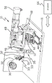
Fig. 1 is a view of a wire bonding tool according to an embodiment of the present invention.
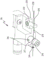
Fig. 2 is a detailed view of the wire clamp assembly of the tool shown in fig. 1.
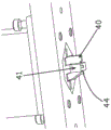
Fig. 3 is a detailed topside view of the pedestal shown in fig. 1 with the components to which the leads are required to be attached.
Fig. 4 is a detailed view of the crimp punch and cutting tool of the wire bonding tool shown in fig. 1.
Fig. 5 is a schematic view of a portion of a component that may have wire bonded by the tool of fig. 1 and a wire feed path used by the tool.
Fig. 6a to 6n are schematic views of portions of the tool of fig. 1, illustrating the sequence of operations performed by the tool to bond a wire to a component.
FIG. 7 is a view of a parts holder according to an embodiment of the present invention.
FIG. 8 is a schematic diagram of a capillary tube inspection system according to an embodiment of the invention.
Detailed Description
A wire feeding and bonding tool 10 according to an embodiment of the present invention may be generally described with reference to fig. 1-3. As shown, the tool 10 includes a base 11 and a support, such as a stage 12, for holding a component 14 (e.g., a camera lens Optical Image Stabilization (OIS) assembly) to which one or more leads are to be bonded by the tool 14. The wire clamp assembly 16 is mounted to and driven by an actuator, such as a table 18, relative to the base 11. The wire clamp assembly 16 includes a base 20 and a clamp 22 for holding a capillary 24. The capillary tube 24 is a tubular structure having an end portion 26, the end portion 26 having a feed opening 28 at a distal end of the capillary tube 24. In the embodiments comprising the embodiment shown in fig. 2, the end portion is linear. In other embodiments, the end portion is non-linear (e.g., it may be curved). In the illustrated embodiment, the entire length of the capillary 24 is linear. The wire clamp assembly 16 also includes a ruby wire guide 34 and a wire clamp 36. The lead wires 32 to be attached to the component 14 are fed from a feeder 30, such as a spool. In an embodiment, the feeder 30 is driven by a motor (not shown in fig. 1). The wire 32 extends from the feeder 30 through a tensioning mechanism 33 and through an optical micrometer 35 to the wire clamp assembly 16. On the wire clamp assembly 16, the wire extends through a ruby wire guide 34 and a clamp 36 before entering the proximal end of the capillary 24. The wire 32 passes through the capillary 24 and extends out of the feed opening 28. The table 18 moves the wire clamp assembly 16 relative to the stage 12 about one or more axes to position the capillary and the wire 32 extending from the feed opening 28 relative to a structure on the component 14 to which the wire is to be bonded. In an embodiment, stage 18 moves the capillary tube about the x, y, z, and θ axes (i.e., four degrees of freedom). The capillary tube holder 22 allows the capillary tube 24 to be easily replaced in the event of damage. The wire clamp 36 includes a base member 37 and a movable member 39. An actuator (such as a solenoid, not shown) drives the movable member 39 relative to the base member 37 between a release position that allows the wire 32 to be fed to the capillary 24 and a clamping position that prevents movement of the wire relative to the capillary.
As shown in fig. 7, the embodiment of the tool 10 also includes a part holder 100', which part holder 100' is incorporated into a die set having crimp punches 40, 41 and a cutting tool 44. In the illustrated embodiment, the clamp 100' has four clamp pads 102' extending from a base 104 '. The clamp pad 102' is configured and positioned to engage the component 14 positioned on the pedestal 12. In an embodiment, part clamp 100' is reciprocally driven or actuated by cam 46.
A control system 66, shown generally in fig. 1, is coupled to the table 18, the wire feed motor, the micrometer 35, the wire clamp actuator, the motor 50, and the actuator 60. In an embodiment, the control system 66 is a programmed controller. As described in more detail below, during operation of the tool 10, the control system 66: (1) actuating stage 18 to position capillary 24 relative to the portion of wire 32 extending from feed opening 28 such that the portion of wire 32 extending from feed opening 28 is presented at a wire attach structure on component 14; (2) actuating the stage 18 to move the capillary 24 along the wire feed path between the attachment structures on the component 14; (3) actuating the motor 50 to drive the punch 40 and the punch 41; (4) actuating the motor 50 to drive the cutting tool 44; (5) actuating the wire feed motor to feed or feed the wire from the feeder 30; and (6) actuating the wire clamp 36 to clamp the wire 32 relative to the clamp assembly 16 (and thus relative to the capillary 24); and (7) actuating motor 50 to drive part clamp 100' in an embodiment.
In an embodiment, the micrometer 35 provides information to the control system 66 about the wire 32 being fed through the micrometer, and the control system may use this information to actively adjust and control the wire feeding operation. For example, some embodiments of the invention may be used with coated wires having spaced apart uncoated regions at the locations where the wires are to be attached to the component 14. In such an embodiment, a micrometer 35 may be used to provide information indicative of the location of the uncoated lead area. Other embodiments include other types of micrometers or other structures for providing information indicative of the wire 32 fed from the feeder 30. In an embodiment, the wire feed motor may be a stepper motor with an encoder to provide information to the control system 66 indicative of the amount of actuation of the motor or feeder 30.
The tensioning mechanism 33 may include a pendulum or dancer arm 51 with a counterweight and a rotational position sensor 52. The position sensor 52 is coupled to the control system 66 and provides information indicative of the position of the dancer arm 51. The lead guide 53 is mounted to the end of the dancer arm 51 by a pivot bearing. For example, as shown in fig. 1, the wire 32 is routed between the feeder 30 and the gripper assembly 16 by the wire guide 53, and the dancer arm 51 and the wire guide are moved away from bottom dead center with respect to the axis of rotation of the position sensor 52. The weight of the dancer arm 51 and the lead guide 53 provides tension on the lead 32. The rotational position sensor 52 provides information to the control system 66 regarding the position of the dancer arm 51 to enable the control system to hold the dancer arm in place to provide a desired amount of tension on the lead 32 (e.g., holding the dancer arm position substantially constant will provide a constant tension on the lead).
In an embodiment, the tool 10 is configured to attach a shape memory alloy (e.g., nitinol) lead 32 to the component 14 in the form of an actuator of a camera lens Optical Image Stabilization (OIS) system, such as the optical image stabilization system generally described in PCT international application publication No. WO 2014/083318. For example, as shown in FIG. 3, the actuator component 14 is a quadrilateral and generally square member having a first or stationary member 70 and a second or movable member 72. Each side of the component 14 includes a first wire attach structure in the form of a crimp 74 on the fixed member 70 and a second wire attach structure in the form of a crimp 76 on the movable member 72. The tool 10 attaches a length of wire 32 between crimps 74 and 76 on each side of the component 14.
Fig. 5 is a schematic view of portions of the fixed member 70 and the crimp 74 and the movable member 72 and the crimp 76 on one side of the component 14. A lead axis 80 is shown corresponding to the location of a length of lead 32 extending between crimp 74 and crimp 76 and attached to component 14 by crimps 74 and 76. As described in more detail below, during the attachment process, the end of the wire 32 (not shown in fig. 5) extending from the feed opening 28 of the capillary 24 is presented and attached to a first attachment structure, such as a crimp 76. Subsequently, the capillary 24 is driven along the feed path 82 to feed the wire from the crimp 76 to a second wire attachment structure, such as the crimp 74. During this wire feeding operation, the end portion 26 of the capillary 24 is held in an orientation sufficient for the wire 32 to exit the feed opening 28 coaxially with the wire axis 80, thereby preventing, minimizing, or at least reducing the chance of damage to the wire 32. In the illustrated embodiment, for example, the linear end portion 26 of the capillary 24 (or the entire length of the capillary if the capillary 24 is linear) is held in an orientation sufficient to be coaxial with the wire axis 80, thereby preventing, minimizing, or at least reducing the chance of damage to the wire 32. In an embodiment (not shown in fig. 5), the wire feed path may be coaxial with the wire axis 80. In other embodiments, such as the embodiment shown in fig. 5, the lead feed path 82 has at least a portion that is not coaxial with the lead path 80. As shown, the wire feed path 82 includes a first section 84 and a second section 86, the first section 84 feeding the wire 32 from the crimp 76 to a position where the crimp 74 is opposite the crimp 76 and the wire is outside the crimp 74, and the second section 86 moving the wire into the crimp 74. The first path section 84 is angled and oriented relative to the wire axis 80 to provide clearance between the capillary 24 (and optionally other components of the tool 10) and the crimp 74. In an embodiment, the angle between the first segment 84 of the feed path 82 and the lead path 80 is relatively small to prevent, minimize, or at least reduce damage to the lead 32 during the feeding process. The second section 86 of the wire feeding path 82 is relatively short relative to the length of the first path section 84 and moves the wire 32 into the crimp 74 so that the wire 32 can be engaged by deforming the crimp. In the illustrated embodiment, the first path section 84 is linear and the second path section 86 is substantially linear and perpendicular to the first path section. In the illustrated embodiment, the end portion 26 of the capillary 24 is oriented substantially parallel to the wire axis 80 as the capillary is moved along the wire feed path 82. In other embodiments, the distal portion 26 is oriented substantially parallel to the first path section 84 as the capillary tube is driven along the first path section. To prevent, minimize, or at least reduce damage to wire 32 during operation of tool 10, other embodiments include other wire feed paths and orientations of distal portion 26 of capillary 24. For example, in other embodiments (e.g., as shown in fig. 6 g), the second path section 86 is a circular path from a location outside of the crimp 74, across the top of the open crimp, and into the open crimp.
Fig. 6a to 6n show an embodiment of the operation of the tool 10. The stand 12 and actuator 60 are withdrawn from their operative positions relative to other components of the tool 10, such as the clamp assembly 16 and table 18, to provide access to the stand. The leadless component 14 is positioned on the pedestal 12 and clamped (e.g., by the clamp 100 in the embodiment shown in fig. 6 a-6 n) to the pedestal 12. Subsequently, the pedestal 12 and the actuator 60 are returned to the operation position where the segment of the lead wire 32 is attached. During a mounting operation, the wire 32 is fed from the feeder 30 to the capillary 24, and a defined amount of the wire is exposed beyond the feed opening 28 of the capillary. In other embodiments having a parts clamp 102', such as described in connection with fig. 7, pedestal 12 with component 14 thereon is returned to the operating position in an undamped state and motor 50 is actuated to move the parts clamp and engage the component to secure the component to the pedestal. In these embodiments, the parts clamp 102' remains engaged with the component 14 throughout the wire feeding and attachment process described below, and upon completion of the process, the motor 50 is actuated to withdraw the parts clamp from the component before the pedestal and the wire-attached portion move from the operating position to the withdrawn position.
Fig. 6a shows the stand 12 in a first position and orientation and the wire clamp assembly 16 in a first or home position, the first side of the component 14 having two unformed crimps 74 and 76, with the end of the wire 32 extending from the feed opening 28 of the capillary 24 in a position spaced relative to the crimps. As shown in fig. 6b and 6c, the wire 32 is clamped by the wire clamp 36 relative to the wire clamp assembly 16, and the wire clamp assembly 16 is driven relative to the component 14 from the position shown in fig. 6a to a position at which the capillary 24 presents an end of the wire 32 within the crimp 76. In an embodiment, during such movement of the clamp assembly 16, the wire feed motor is actuated to feed wire from the supply 30 while maintaining a desired tension on the wire 32 between the supply and the wire clamp 36. Subsequently, as shown in fig. 6d and 6e, the first crimping punch 40 is actuated to deform the crimp 76 and engage it and attach the lead 32.
As shown in fig. 6f and 6g, after the wire 32 is attached to the crimp 76, the wire clamp 36 is actuated to release the wire 32, and the wire clamp assembly 16 is driven relative to the crimp 76 to expose the wire from the capillary 24 and feed the wire along a wire feed path (e.g., path 82 as shown in fig. 5) and position the wire within the crimp 74. The amount of wire 32 exposed during this feeding operation is determined by the spacing between crimps 74 and 76 and any amount of additional slack or "snapping" of the wire that is required in the section of the wire between the crimps. Subsequently, the wire clamp 36 is actuated to clamp the wire 32, and the wire clamp assembly 16 is actuated to move the capillary 24 back toward the crimp 76, thereby pushing a desired amount of slack into the wire between the crimp 76 and the crimp 74. During this operation, the engagement between the capillary 24 and the wire 32 helps to ensure that the required slack is located between the crimp 76 and the crimp 74 (i.e., not between the wire clamp 36 and the proximal end of the capillary). After the wire 32 is properly positioned and tensioned within the open crimp 74 by the above process, the second crimp punch 41 is actuated to deform the crimp 74 and engage and attach the wire 32 to the crimp 74, as shown in fig. 6 h.
After the wire is attached to crimps 76 and 74, wire clamp 36 is actuated to release wire 32. The wire clamp assembly 16 is then driven away from the crimp 74 a distance sufficient to enable the wire 32 to be cut and a desired length of wire to be fed out of the capillary 24 to be positioned within the first crimp on the lower side of the component 14. Subsequently, the wire clamp 36 is actuated to clamp the wire 32 to the wire clamp assembly 16, and then as shown in fig. 6i, the cutting tool 44 is actuated to sever the wire between the crimp 74 and the feed opening 28. Subsequently, a suitable amount of exposed wire for the next attachment sequence extends from the feed opening 28. In the embodiment shown in fig. 6j and 6k, the punch 40 and punch 41 and cutting tool 44 are then retracted, and the wire clamp assembly 16 is actuated and returned to its original position as shown in fig. 6 l. In other embodiments, a sufficient length of wire 32 to ensure that the wire is severed is fed or fed during the wire feeding and feeding steps described in connection with fig. 6f and 6 g. Including (1) actuating the wire clamp 36 to release the wire 32; (2) driving the wire clamp assembly 16 away from the crimp 74 to provide additional and desired length of wire to ensure the severing step; and (3) the step of actuating the wire clamp to clamp the wire as described above in connection with fig. 6i can be eliminated by this method to increase the wiring assembly cycle time.
As shown in fig. 6m and 6n, after the section of wire 32 is attached to crimps 74 and 76 on the first side of component 14, actuator 60 is actuated to rotate pedestal 12 (e.g., 90 °), and position the other (e.g., second) side of component 14 having crimps 74 and 76 relative to wire clamp assembly 16. Subsequently, the process described and illustrated with respect to fig. 6 a-6 l is repeated to attach the second segment of the wire 32 to the crimps 74 and 76 on the second side of the component 14. Subsequently, the processes described and illustrated above are repeated to attach the segments of the wire 32 to the crimps 74 and 76 on the third and fourth sides of the component 14. The pedestal 12 and actuator 60 are withdrawn from their operating positions relative to the clamp assembly 36 and table 18, and the component 14 with the attached sections of the leads 32 can be removed from the pedestal 12. Subsequently, the process described and illustrated above may be repeated for another component 14.
FIG. 8 is a view of a capillary tube inspection system 150 that may be used with the tool 10. As shown, the inspection system 150 includes one or more imaging devices, such as a camera 152, coupled to an image processor 154. The image processor 154 may be hardware and/or software based and may be included in the control system 66. Capillaries such as 24 may be fragile machined components and may be damaged during operation of the tool 10 (e.g., by handling by an operator). Manufacturing tolerances also occur for the capillary 24. The inspection system 150 may be used to identify damaged, misaligned, or otherwise out of tolerance capillaries 24. During tool installation, a rigid and precise fixture (not shown) that replicates the shape, tolerances, and other characteristics and features of capillary 24 required is mounted to wire clamp assembly 16. The capillary mount fixture is imaged by a camera 152 and the image is received by an image processor 154 and used by the image processor as a frame of reference. After the frame of reference is established, the capillary mount fixture is removed and the capillary 24 is positioned within the wire clamp assembly 16. Images (also generated by the camera 152) of the capillary tube are processed and evaluated (e.g., compared to a frame of reference) by the processor 154 after installation of the capillary tube 24 prior to operation of the tool 10 and/or periodically during operation of the tool. If the capillary change is identified as being of a type and/or degree that is within a predetermined threshold (e.g., if the position of the feed opening 28 is slightly misaligned or offset from a desired position), the control system 66 may compensate for the change during the wire attachment process. If the identified capillary change is of a type and/or amount greater than a predetermined threshold, the image processor or control system 66 may issue an alert to the operator. The operator can then take appropriate action.
Wire bonding tools and related methods provide a number of important advantages. Leads such as SMA wires attached to the OIS component are relatively fragile and susceptible to damage (e.g., when bonding the leads to the component). Supporting the wire within the capillary during bonding and other processes using the wire can prevent, minimize, or at least reduce damage to the wire. By way of non-limiting example, in some embodiments, the diameter of the nitinol lead 32 attached to an OIS component, such as 14 (including the outer coating), is approximately 27-29 μm. In these embodiments, it has been determined that the use of stainless steel and a capillary 24 having an inner diameter of about 38 μm provides the above-described type of advantages. Other embodiments use capillaries and leads having other dimensions. The capillary 24 may also be formed from other materials, such as polymers. Dispensing the wire coaxially from the capillary or at a relatively small angle relative to the coaxial reduces damage to the wire while allowing the wire to be manipulated. In addition to improving the efficiency of the wire attach process, the tool can also increase the speed of the attach process, thereby increasing the yield of the attach process.
Although the present invention has been described with reference to preferred embodiments, workers skilled in the art will recognize that changes may be made in form and detail without departing from the spirit and scope of the invention.
For example, in other embodiments, one or more lead segments may be attached to the component by different routing/assembly tools (e.g., at different stations, as an alternative to rotating the component relative to a single attachment tool). Each such routing/assembly tool may be dedicated to attaching lead segments to one side of the component, and the components may be transferred between tools. The method of attaching the wire segments at such different tools may be the same or similar to the method described above.
Different wire feed, clamping and/or tensioning configurations may be implemented. For example, the gripper 36 may be actuated by a piezoelectric or micro-motor actuator to increase speed. In the embodiment described in connection with fig. 1, the wire tension provided by the tensioning mechanism is primarily maintained throughout the routing process with respect to the portion of the wire that is secured or secured by the clamp assembly, crimp, or other attachment structure. The fastening or securing function is periodically switched between the clamp assembly and the crimp. In the event that the wire is not adequately maintained by the crimp and the clamp is open, the wire tension may cause the wire to pass through and exit the capillary (i.e., in a direction opposite and away from the feed opening). This type of "drop" accident can result in tool downtime to re-thread the wire into the capillary and complete the associated installation process. Embodiments of the present invention incorporate a lead retention mechanism, which reduces the chance of such a drop event. For example, embodiments include slip clutches, rollers, and/or other mechanisms that do not completely release the wire. One such mechanism may allow the wire to slide in one direction (i.e., the feed direction) by tightly controlling the sliding tension threshold, while not allowing the wire to slide in the other direction. Another mechanism uses a roller contactor to maintain the wire and a target slip-clutch device to selectively control wire slip. Embodiments that use a driven roller to feed out the wire (e.g., having a motor coupled to a control system) would have certain advantages. The same rollers can be used to simplify the initial installation by automating the capillary threading process, clearing any potentially damaged wire, and synchronizing the position of the uncoated wire segments. Certain steps in the wire attach process may be performed more efficiently by sending out additional wire rather than through the unclamping/translating/reclamping/translating process of the embodiment described in connection with fig. 1.
The wire feed through the embodiment described in connection with fig. 1 is accomplished by moving the clamp assembly (and capillary) about x, y, z and theta axes (e.g., four degrees of freedom) relative to the relatively stationary components (rather than by rotating the components to present different sides of the components by an actuated stand). The same or similar relative wire feed (e.g., wire feed path) may be achieved by movement of the components by providing some or all degrees of freedom of movement. For example, in an embodiment, the tool is configured with a gripper assembly that translates about the x-axis and the y-axis and a stage that is driven by actuators located on the z-axis and the θ -axis. Wire feed paths such as those described above may be achieved through different combinations of movement of the clamp assembly and components (e.g., the stage may be driven through a relatively small range of motion about the z-axis and theta-axis instead of the clamp assembly).
Claims (30)
1. A wire feeding and bonding tool comprising:
a support for holding a component to which a wire is to be attached, wherein the component has at least first and second spaced apart wire attach structures to which a wire is attachable, a first wire axis extending between the first and second wire attach structures;
a wire feed system, the wire feed system comprising:
a capillary having an end portion with a feed opening, wherein a wire to be attached to the wire attach structure can be fed through the capillary and extend from the feed opening;
a stage for moving the capillary relative to the support about one or more axes to position the capillary and the wire extending from the feed opening;
an attachment tool positioned relative to the support to attach the lead to the attachment structure;
a cutting tool positioned relative to the support to sever the lead; and
a control system coupled to the table, the attachment tool, and the cutting tool, wherein the control system:
actuating the stage to position the capillary such that a portion of the wire extending from the feed opening is presented at the first and second wire attach structures;
actuating the stage to move the capillary along a wire feed path and feed the wire from the first wire attach structure to the second wire attach structure such that the wire exiting the feed opening is sufficiently coaxial with the wire axis to reduce damage to the wire;
actuating the attachment tool to attach the wire to the first and second wire attach structures; and
actuating the cutting tool to sever the wire.
2. The wire feeding and bonding tool of claim 1 wherein all or substantially all of the capillary is linear.
3. The wire feeding and bonding tool of claim 1 further comprising a capillary clamp mounted to the table to releasably hold the capillary.
4. The wire feeding and bonding tool of claim 1 wherein the component has a crimp-style wire attachment structure and:
the control system actuates the stage to position the capillary such that the portion of the wire extending from the feed opening extends into a crimp; and
the attachment tool includes at least one punch for deforming the crimp member such that the crimp member engages a portion of the lead within the crimp member.
5. The wire feeding and bonding tool of claim 1, wherein:
the control system actuates the stage to move the capillary away from the first wire attachment structure along a first substantially linear portion of the wire feed path; and
the control system actuates the stage to move the capillary in a second portion of the wire feed path that is substantially perpendicular to the first portion of the wire feed path, and the second portion of the wire feed path is shorter than the first portion of the wire feed path.
6. The wire feeding and bonding tool of claim 5 wherein the control system actuates the stage to move the capillary through a loop-like path in the second portion of the wire feed path.
7. The wire feeding and bonding tool of claim 1 wherein the control system:
actuating the stage to position the capillary such that an end of the wire extending from the feed opening is adjacent the first wire attach structure;
actuating the attachment tool to attach the end of the wire adjacent the first wire attach structure to the first wire attach structure;
after the wire is attached to the first wire attach structure, actuating the stage to move the capillary along the wire feed path and position a portion of the wire extending from the capillary adjacent to the second wire attach structure;
actuating the attachment tool to attach the portion of the wire adjacent the second wire attach structure to the second wire attach structure; and
actuating the cutting tool to disconnect the portion of the wire attached to the second wire attach structure from a portion extending from the feed opening.
8. The wire feeding and bonding tool of claim 7 wherein the component has a first crimp wire attach structure and a second crimp wire attach structure, and wherein:
the control system actuates the stage to position the capillary such that the wire extends from the feed opening into a crimp; and
the attachment tool includes at least one punch for deforming the crimp member such that the crimp member engages a portion of the lead within the crimp member.
9. The wire feeding and bonding tool of claim 8, wherein:
the attachment tool comprises a first punch and a second punch;
the control system actuates the first punch to deform the first crimp; and
the control system actuates the second punch to deform the second crimp.
10. The wire feeding and bonding tool of claim 9, wherein:
the control system actuates the stage to move the capillary away from the first crimp along a first substantially linear portion of the wire feed path; and
the control system actuates the stage to move the capillary in a second portion of the wire feed path that is substantially perpendicular to the first portion of the wire feed path to position wire within the second crimp, and the second portion of the wire feed path is shorter than the first portion of the wire feed path.
11. The wire feeding and bonding tool of claim 10 wherein the control system actuates the stage to move the capillary through a looped path in the second portion of the wire feed path.
12. The wire feeding and bonding tool of claim 9 wherein the component has at least a third and a fourth crimp wire attach structure, and a second wire attach axis that is non-collinear with the first wire attach axis extends between the third and fourth crimps, and:
the tool further includes a buttress actuator coupled to the control system for rotating the buttress relative to the wire feed system; and
the control system is:
actuating the buttress actuator to rotate the buttress and the component retained on the buttress;
actuating the stage to position the capillary such that an end of the wire extending from the feed opening enters into the third crimp;
actuating the first punch to deform the third crimp and attach the lead to the third crimp;
after the wire is attached to the third crimp, actuating the stage to move the capillary along the wire feed path and position a portion of the wire extending from the capillary into the fourth crimp;
actuating the second punch to deform the fourth crimp and attach the lead to the fourth crimp; and
actuating the cutting tool to disconnect a portion of the wire attached to the fourth crimp from a portion extending from the feed opening.
13. The wire feeding and bonding tool of claim 12 wherein the control system actuates the holder actuator to rotate the holder and the component held on the holder about 90 degrees.
14. The wire feeding and bonding tool of any of claims 1 and 7 further comprising a tensioning device to tension the wire.
15. The wire feeding and bonding tool of any of claims 1 and 7,
the capillary tube includes a linear end portion; and
the control system actuates the stage to move the capillary such that the linear end portion is sufficiently coaxial with the wire axis to reduce damage to the wire.
16. The wire feeding and bonding tool of claim 1 wherein the component has at least a third wire attach structure and a fourth wire attach structure, and a second wire attach axis that is non-collinear with the first wire attach axis extends between the third wire attach structure and the fourth wire attach structure, and wherein:
the wire feeding and bonding tool further comprises a holder actuator coupled to the control system for moving the holder relative to the wire feeding system; and
the control system is:
actuating the support actuator to move the support and the component held on the support;
actuating the stage to position the capillary such that an end of the wire extending from the feed opening is adjacent the third wire attach structure;
actuating the attachment tool to attach the wire to the third wire attach structure;
after the wire is attached to the third wire attach structure, actuating the stage to move the capillary along the wire feed path and position a portion of the wire extending from the capillary adjacent to the fourth wire attach structure;
actuating the attachment tool to attach the wire to the fourth wire attach structure; and
actuating the cutting tool to disconnect the portion of the wire attached to the fourth wire attach structure from a portion extending from the feed opening.
17. A method for attaching a wire to a component having first and second spaced apart wire attach structures, the method comprising:
feeding the wire through a capillary having a feed opening;
positioning the capillary such that a first portion of the wire extending from the feed opening is positioned adjacent the first wire attach structure;
attaching the first portion of the lead to the first lead attachment structure;
moving the capillary relative to the component along a wire feed path to feed the wire from the first wire attach structure to the second wire attach structure and position a second portion of the wire extending from the feed opening adjacent the second wire attach structure;
attaching the second portion of the wire to the second wire attach structure such that the wire exiting the feed opening is sufficiently coaxial with the wire axis to reduce damage to the wire.
18. The method of claim 17, wherein moving the capillary tube comprises:
moving the capillary away from the first wire attach structure along a first and substantially linear portion of the wire feed path; and
after moving the capillary along the first portion of the wire feed path, moving the capillary along a second portion of the wire feed path to position the second portion of the wire adjacent to the second wire attach structure, wherein the second portion of the wire feed path is substantially perpendicular to the first portion of the wire feed path.
19. The method of claim 18, wherein the capillary has a linear end portion, and moving the capillary comprises maintaining the linear end portion of the capillary sufficiently coaxial with the wire axis to reduce damage to the wire.
20. The method of claim 19, wherein the second portion of the wire feed path is shorter than the first portion of the wire feed path.
21. The method of claim 20, wherein moving the capillary along the second portion of the wire feed path comprises moving the capillary along a looped path.
22. The method of claim 21, wherein:
moving the capillary along the second portion of the wire feed path comprises moving the wire into an opening of a crimp-style attachment structure; and
attaching the second portion of the wire to the second wire attach structure includes deforming the crimp-style attachment structure to bond the wire.
23. The method of any of claims 17 and 22, further comprising clamping and releasing the wire with respect to the capillary.
24. The method of any one of claims 17, 18 and 20, further comprising tensioning the wire.
25. The method of claim 17, wherein the capillary has a linear end portion, and moving the capillary comprises maintaining the linear end portion of the capillary sufficiently coaxial with the wire axis to reduce damage to the wire.
26. The method of claim 17, further comprising disconnecting the wire between the second wire attach structure and the capillary after attaching the second portion of the wire to the second wire attach structure.
27. The method of claim 17, wherein:
moving the capillary tube comprises:
moving the capillary away from the first wire attach structure toward the second wire attach structure while feeding wire from the capillary;
clamping the wire relative to the capillary after moving the capillary away from the first wire attach structure;
moving the capillary together with the clamped wire toward the first wire attach structure to push slack into the wire between the first and second wire attach structures; and
attaching the second portion of the wire to the second wire attach structure comprises attaching the wire to the second wire attach structure after moving the capillary to push slack into the wire.
28. The method of claim 17, further comprising:
monitoring the wire to identify a location of an uncoated region on the wire; and
adjusting a position of the wire relative to the capillary based on the identified location of the uncoated region on the wire.
29. The wire feeding and bonding tool of claim 1, wherein:
the tool further includes a monitor for identifying a location of an uncoated region on the wire; and
the control system is coupled to the monitor and causes a position of the wire relative to the capillary to be adjusted according to the identified position of the uncoated region on the wire.
30. The method of claim 17, wherein moving the capillary relative to the member comprises moving the capillary and the member.
Applications Claiming Priority (3)
| Application Number | Priority Date | Filing Date | Title |
|---|---|---|---|
| US201562142182P | 2015-04-02 | 2015-04-02 | |
| US62/142,182 | 2015-04-02 | ||
| PCT/US2016/025194 WO2016161075A1 (en) | 2015-04-02 | 2016-03-31 | Wire feeding and attaching system for camera lens suspensions |
Publications (2)
| Publication Number | Publication Date |
|---|---|
| CN107533990A CN107533990A (en) | 2018-01-02 |
| CN107533990B true CN107533990B (en) | 2020-09-22 |
Family
ID=57006487
Family Applications (1)
| Application Number | Title | Priority Date | Filing Date |
|---|---|---|---|
| CN201680024732.1A Active CN107533990B (en) | 2015-04-02 | 2016-03-31 | Lead feed and attachment system for camera lens mount |
Country Status (6)
| Country | Link |
|---|---|
| US (3) | US10840662B2 (en) |
| EP (1) | EP3278354B1 (en) |
| JP (1) | JP6637516B2 (en) |
| KR (1) | KR102519325B1 (en) |
| CN (1) | CN107533990B (en) |
| WO (1) | WO2016161075A1 (en) |
Families Citing this family (8)
| Publication number | Priority date | Publication date | Assignee | Title |
|---|---|---|---|---|
| US9366879B1 (en) | 2014-12-02 | 2016-06-14 | Hutchinson Technology Incorporated | Camera lens suspension with polymer bearings |
| US9454016B1 (en) | 2015-03-06 | 2016-09-27 | Hutchinson Technology Incorporated | Camera lens suspension with integrated electrical leads |
| KR102519325B1 (en) * | 2015-04-02 | 2023-04-10 | 허친슨 테크놀로지 인코포레이티드 | Wire transport and attachment system for camera lens suspension |
| US10670878B2 (en) | 2016-05-19 | 2020-06-02 | Hutchinson Technology Incorporated | Camera lens suspensions |
| KR20190015528A (en) | 2016-06-09 | 2019-02-13 | 허친슨 테크놀로지 인코포레이티드 | Shape memory alloy wire attachment structure having an adhesive for a suspension assembly |
| CN106944827B (en) * | 2017-05-04 | 2022-12-09 | 惠州市德赛自动化技术有限公司 | Mobile phone lens assembling equipment |
| DE102019000856A1 (en) * | 2019-02-06 | 2020-08-06 | Diehl Metal Applications Gmbh | Establishing a low-voltage path of a cell contacting system |
| GB2611338B (en) * | 2021-09-30 | 2024-04-03 | Cambridge Mechatronics Ltd | Apparatus and methods for assembling an actuating module |
Citations (2)
| Publication number | Priority date | Publication date | Assignee | Title |
|---|---|---|---|---|
| US4437603A (en) * | 1980-01-07 | 1984-03-20 | Hitachi, Ltd. | Automatic wiring machine for printed circuit boards |
| US4781319A (en) * | 1985-05-31 | 1988-11-01 | Dynapert Delvotec S.A. | Bonding head |
Family Cites Families (42)
| Publication number | Priority date | Publication date | Assignee | Title |
|---|---|---|---|---|
| CH457131A (en) | 1967-09-06 | 1968-05-31 | Koch Carl | Photographic focusing screen camera |
| US3776447A (en) | 1969-06-30 | 1973-12-04 | Texas Instruments Inc | Automatic semiconductor bonding machine |
| US3734386A (en) * | 1971-06-30 | 1973-05-22 | Ibm | Wiring apparatus with wire path forming means |
| US4140265A (en) * | 1975-06-26 | 1979-02-20 | Kollmorgen Technologies Corporation | Method and apparatus for positioning the end of a conductive filament at a predetermined and repeatable geometric location for coupling to a predetermined terminal area of an element |
| US4586642A (en) * | 1985-05-13 | 1986-05-06 | Kulicke And Soffa Industries Inc. | Wire bond monitoring system |
| US4824005A (en) | 1986-08-13 | 1989-04-25 | Orthodyne Electronics Corporation | Dual mode ultrasonic generator in a wire bonding apparatus |
| JP2959322B2 (en) | 1993-03-09 | 1999-10-06 | 住友電装株式会社 | Harness electric wire manufacturing apparatus and manufacturing method |
| US5402927A (en) * | 1994-06-09 | 1995-04-04 | Kulicke And Soffa Investments, Inc. | Adjustable wire tensioning apparatus |
| JP3488100B2 (en) * | 1998-10-13 | 2004-01-19 | 矢崎総業株式会社 | Automatic cutting and crimping equipment |
| TW522532B (en) * | 2000-11-07 | 2003-03-01 | Siliconware Precision Industries Co Ltd | Schemes for detecting bonding status of bonding wire of semiconductor package |
| US7384531B1 (en) | 2004-02-19 | 2008-06-10 | Hutchinson Technology Incorporated | Plated ground features for integrated lead suspensions |
| WO2005114658A2 (en) | 2004-05-14 | 2005-12-01 | Hutchinson Technology Incorporated | Method for making noble metal conductive leads for suspension assemblies |
| US7679647B2 (en) | 2004-07-21 | 2010-03-16 | Hewlett-Packard Development Company, L.P. | Flexible suspension for image stabilization |
| EP1807239A2 (en) * | 2004-11-02 | 2007-07-18 | Imasys AG | Laying device, contacting device, advancing system, laying and contacting unit, production system, method for the production and a transponder unit |
| JP4530984B2 (en) * | 2005-12-28 | 2010-08-25 | 株式会社新川 | Wire bonding apparatus, bonding control program, and bonding method |
| US8350959B2 (en) | 2006-03-30 | 2013-01-08 | 1 . . . Limited | Camera lens actuation apparatus |
| US8286332B2 (en) * | 2006-09-26 | 2012-10-16 | Hid Global Gmbh | Method and apparatus for making a radio frequency inlay |
| US7929252B1 (en) | 2006-10-10 | 2011-04-19 | Hutchinson Technology Incorporated | Multi-layer ground plane structures for integrated lead suspensions |
| US7832082B1 (en) | 2006-10-10 | 2010-11-16 | Hutchinson Technology Incorporated | Method for manufacturing an integrated lead suspension component |
| JP2008233526A (en) | 2007-03-20 | 2008-10-02 | Tamron Co Ltd | Actuator for preventing image shake and camera equipped therewith |
| US8169746B1 (en) | 2008-04-08 | 2012-05-01 | Hutchinson Technology Incorporated | Integrated lead suspension with multiple trace configurations |
| JP4625858B2 (en) * | 2008-09-10 | 2011-02-02 | 株式会社カイジョー | Wire bonding method, wire bonding apparatus, and wire bonding control program |
| EP2326984A2 (en) | 2008-09-12 | 2011-06-01 | Cambridge Mechatronics Limited | Optical image stabilisation comprising shape memory alloy actuators |
| WO2010089529A1 (en) | 2009-02-09 | 2010-08-12 | Cambridge Mechatronics Limited | Optical image stabilisation |
| JP2011039485A (en) | 2009-07-14 | 2011-02-24 | Seiko Instruments Inc | Drive module and electronic device |
| JP4804564B2 (en) | 2009-07-14 | 2011-11-02 | キヤノン株式会社 | Optical apparatus having shake correction device |
| JP5846346B2 (en) | 2009-08-21 | 2016-01-20 | ミツミ電機株式会社 | Camera shake correction device |
| JP2011127585A (en) | 2009-11-17 | 2011-06-30 | Morioka Seiko Instruments Inc | Actuator manufacturing method, actuator, drive module manufacturing method, drive module, and electronic apparatus |
| US8885299B1 (en) | 2010-05-24 | 2014-11-11 | Hutchinson Technology Incorporated | Low resistance ground joints for dual stage actuation disk drive suspensions |
| GB2495887B (en) | 2010-08-09 | 2016-12-28 | Cambridge Mechatronics Ltd | Camera apparatus |
| GB201019532D0 (en) | 2010-11-18 | 2010-12-29 | Cambridge Mechatronics Ltd | Optical image stablisation drive |
| CA2818301A1 (en) | 2010-11-22 | 2012-05-31 | Senseair Ab | Method for the wafer-level integration of shape memory alloy wires |
| KR20130098635A (en) * | 2012-02-28 | 2013-09-05 | 삼성전자주식회사 | Capillary exchange system of semiconductor wire bond |
| GB201206490D0 (en) | 2012-04-12 | 2012-05-30 | Cambridge Mechatronics Ltd | Compact camera |
| JP6289451B2 (en) | 2012-05-25 | 2018-03-07 | ケンブリッジ メカトロニクス リミテッド | Shape memory alloy actuator |
| GB201220485D0 (en) | 2012-11-14 | 2012-12-26 | Cambridge Mechatronics Ltd | Control of an SMA actuation apparatus |
| WO2014077232A1 (en) * | 2012-11-16 | 2014-05-22 | 株式会社新川 | Wire bonding device and wire bonding method |
| GB201221306D0 (en) | 2012-11-27 | 2013-01-09 | Cambridge Mechatronics Ltd | Suspension system for a camera lens element |
| WO2014100516A1 (en) | 2012-12-20 | 2014-06-26 | Bynlac Laboratories Llc | Voice coil motor optical image stabilization |
| GB201403803D0 (en) | 2014-03-04 | 2014-04-16 | Cambridge Mechatronics Ltd | SMA actuator |
| GB201412848D0 (en) | 2014-07-18 | 2014-09-03 | Cambridge Mechatronics Ltd | Suspension system for a camera lens element |
| KR102519325B1 (en) | 2015-04-02 | 2023-04-10 | 허친슨 테크놀로지 인코포레이티드 | Wire transport and attachment system for camera lens suspension |
-
2016
- 2016-03-31 KR KR1020177031353A patent/KR102519325B1/en active IP Right Grant
- 2016-03-31 CN CN201680024732.1A patent/CN107533990B/en active Active
- 2016-03-31 WO PCT/US2016/025194 patent/WO2016161075A1/en active Application Filing
- 2016-03-31 US US15/086,871 patent/US10840662B2/en active Active
- 2016-03-31 JP JP2017551683A patent/JP6637516B2/en active Active
- 2016-03-31 EP EP16774169.3A patent/EP3278354B1/en active Active
-
2020
- 2020-11-16 US US17/099,481 patent/US11769977B2/en active Active
- 2020-11-16 US US17/099,373 patent/US11682876B2/en active Active
Patent Citations (2)
| Publication number | Priority date | Publication date | Assignee | Title |
|---|---|---|---|---|
| US4437603A (en) * | 1980-01-07 | 1984-03-20 | Hitachi, Ltd. | Automatic wiring machine for printed circuit boards |
| US4781319A (en) * | 1985-05-31 | 1988-11-01 | Dynapert Delvotec S.A. | Bonding head |
Also Published As
| Publication number | Publication date |
|---|---|
| US11682876B2 (en) | 2023-06-20 |
| KR20170136556A (en) | 2017-12-11 |
| CN107533990A (en) | 2018-01-02 |
| EP3278354B1 (en) | 2024-03-20 |
| WO2016161075A1 (en) | 2016-10-06 |
| US20160294141A1 (en) | 2016-10-06 |
| KR102519325B1 (en) | 2023-04-10 |
| EP3278354A4 (en) | 2018-11-14 |
| US20210075175A1 (en) | 2021-03-11 |
| US11769977B2 (en) | 2023-09-26 |
| JP2018520889A (en) | 2018-08-02 |
| JP6637516B2 (en) | 2020-01-29 |
| EP3278354A1 (en) | 2018-02-07 |
| US20210075176A1 (en) | 2021-03-11 |
| US10840662B2 (en) | 2020-11-17 |
Similar Documents
| Publication | Publication Date | Title |
|---|---|---|
| CN107533990B (en) | Lead feed and attachment system for camera lens mount | |
| JP5206865B2 (en) | Electronic component winding method and apparatus | |
| US7185411B2 (en) | Method and apparatus for forming fine gauge and monofilament single and double-armed sutures | |
| JP2008545238A (en) | Terminal supply device for connection equipment | |
| EP3616805B1 (en) | Lead wire straightening device | |
| EP2893987B1 (en) | Work processing apparatus and die moving method for work processing apparatus | |
| WO2009017653A1 (en) | Wire positioning device for a wire termination machine | |
| JP2018520889A5 (en) | ||
| CN112805817A (en) | Die attach system and method of attaching a die to a substrate | |
| KR100800208B1 (en) | Trimming device and trimming method | |
| JP2007266271A (en) | Core mounting method and device | |
| JP4299631B2 (en) | Semiconductor device manufacturing equipment | |
| JP2011125982A (en) | Positioning method by automatic machine, and positioning device of the automatic machine | |
| WO2018134912A1 (en) | Component inserting machine | |
| JP7426897B2 (en) | automatic wiring device | |
| CN114765940B (en) | Pin element feeder, substrate alignment machine and method for assembling pin element on circuit substrate | |
| WO2021166248A1 (en) | Holder | |
| CN114472682B (en) | Cutting device and manufacturing device for heat exchanger fin | |
| CN112865478B (en) | Memory alloy motor module, assembly system and assembly method | |
| US11205634B2 (en) | Bonding apparatus with replaceable bonding tool | |
| US20200346808A1 (en) | Attachment of a tray gripper of a tray sealing machine | |
| EP3813503B1 (en) | Electronic component mounting device and control method | |
| JP2008307602A (en) | Method and device for discharging product | |
| KR20200125642A (en) | Apparatus and method for automatic assembly of probe head | |
| KR20230031182A (en) | Bonding device and alignment method |
Legal Events
| Date | Code | Title | Description |
|---|---|---|---|
| PB01 | Publication | ||
| PB01 | Publication | ||
| SE01 | Entry into force of request for substantive examination | ||
| SE01 | Entry into force of request for substantive examination | ||
| GR01 | Patent grant | ||
| GR01 | Patent grant |