CN107529813B - Suction belt conveyor and rod-making machine for the tobacco processing industry, method for measuring material properties of a material rod for the tobacco processing industry and use - Google Patents
Suction belt conveyor and rod-making machine for the tobacco processing industry, method for measuring material properties of a material rod for the tobacco processing industry and use Download PDFInfo
- Publication number
- CN107529813B CN107529813B CN201680020944.2A CN201680020944A CN107529813B CN 107529813 B CN107529813 B CN 107529813B CN 201680020944 A CN201680020944 A CN 201680020944A CN 107529813 B CN107529813 B CN 107529813B
- Authority
- CN
- China
- Prior art keywords
- suction belt
- belt conveyor
- tobacco
- rod
- resonator
- Prior art date
- Legal status (The legal status is an assumption and is not a legal conclusion. Google has not performed a legal analysis and makes no representation as to the accuracy of the status listed.)
- Active
Links
- 239000000463 material Substances 0.000 title claims abstract description 73
- 241000208125 Nicotiana Species 0.000 title claims abstract description 69
- 235000002637 Nicotiana tabacum Nutrition 0.000 title claims abstract description 69
- 238000000034 method Methods 0.000 title claims abstract description 25
- 238000012545 processing Methods 0.000 title claims abstract description 22
- 230000007246 mechanism Effects 0.000 claims description 26
- 230000005540 biological transmission Effects 0.000 claims description 5
- 238000011144 upstream manufacturing Methods 0.000 claims description 4
- 230000005855 radiation Effects 0.000 description 22
- 235000019504 cigarettes Nutrition 0.000 description 20
- 238000005259 measurement Methods 0.000 description 19
- 230000005684 electric field Effects 0.000 description 13
- 238000009826 distribution Methods 0.000 description 10
- 239000000835 fiber Substances 0.000 description 6
- 238000010521 absorption reaction Methods 0.000 description 3
- 238000013461 design Methods 0.000 description 3
- 230000035515 penetration Effects 0.000 description 3
- 238000011160 research Methods 0.000 description 3
- 230000002745 absorbent Effects 0.000 description 2
- 239000002250 absorbent Substances 0.000 description 2
- 239000003990 capacitor Substances 0.000 description 2
- 230000008878 coupling Effects 0.000 description 2
- 238000010168 coupling process Methods 0.000 description 2
- 238000005859 coupling reaction Methods 0.000 description 2
- 238000005520 cutting process Methods 0.000 description 2
- 230000007423 decrease Effects 0.000 description 2
- 238000005516 engineering process Methods 0.000 description 2
- 230000005284 excitation Effects 0.000 description 2
- 239000004744 fabric Substances 0.000 description 2
- 229920000767 polyaniline Polymers 0.000 description 2
- 229920001296 polysiloxane Polymers 0.000 description 2
- 238000003825 pressing Methods 0.000 description 2
- 230000001902 propagating effect Effects 0.000 description 2
- 230000035945 sensitivity Effects 0.000 description 2
- 239000007787 solid Substances 0.000 description 2
- 238000003860 storage Methods 0.000 description 2
- 238000012546 transfer Methods 0.000 description 2
- 238000009966 trimming Methods 0.000 description 2
- 239000006096 absorbing agent Substances 0.000 description 1
- 239000011358 absorbing material Substances 0.000 description 1
- 238000004026 adhesive bonding Methods 0.000 description 1
- 239000005030 aluminium foil Substances 0.000 description 1
- 238000013459 approach Methods 0.000 description 1
- 230000002238 attenuated effect Effects 0.000 description 1
- 238000010276 construction Methods 0.000 description 1
- 238000011109 contamination Methods 0.000 description 1
- 230000007547 defect Effects 0.000 description 1
- 238000001514 detection method Methods 0.000 description 1
- 238000011161 development Methods 0.000 description 1
- 239000006185 dispersion Substances 0.000 description 1
- 230000000694 effects Effects 0.000 description 1
- 239000006260 foam Substances 0.000 description 1
- 239000006261 foam material Substances 0.000 description 1
- 230000010354 integration Effects 0.000 description 1
- 239000002184 metal Substances 0.000 description 1
- 229910052751 metal Inorganic materials 0.000 description 1
- 230000003287 optical effect Effects 0.000 description 1
- 239000002245 particle Substances 0.000 description 1
- 230000000149 penetrating effect Effects 0.000 description 1
- 230000008092 positive effect Effects 0.000 description 1
- 230000008569 process Effects 0.000 description 1
- 238000012216 screening Methods 0.000 description 1
- 238000000926 separation method Methods 0.000 description 1
- 230000002123 temporal effect Effects 0.000 description 1
Images


Classifications
-
- A—HUMAN NECESSITIES
- A24—TOBACCO; CIGARS; CIGARETTES; SIMULATED SMOKING DEVICES; SMOKERS' REQUISITES
- A24C—MACHINES FOR MAKING CIGARS OR CIGARETTES
- A24C5/00—Making cigarettes; Making tipping materials for, or attaching filters or mouthpieces to, cigars or cigarettes
- A24C5/32—Separating, ordering, counting or examining cigarettes; Regulating the feeding of tobacco according to rod or cigarette condition
- A24C5/34—Examining cigarettes or the rod, e.g. for regulating the feeding of tobacco; Removing defective cigarettes
- A24C5/3412—Examining cigarettes or the rod, e.g. for regulating the feeding of tobacco; Removing defective cigarettes by means of light, radiation or electrostatic fields
-
- A—HUMAN NECESSITIES
- A24—TOBACCO; CIGARS; CIGARETTES; SIMULATED SMOKING DEVICES; SMOKERS' REQUISITES
- A24C—MACHINES FOR MAKING CIGARS OR CIGARETTES
- A24C5/00—Making cigarettes; Making tipping materials for, or attaching filters or mouthpieces to, cigars or cigarettes
- A24C5/14—Machines of the continuous-rod type
- A24C5/18—Forming the rod
- A24C5/1857—Belt construction or driving means
-
- A—HUMAN NECESSITIES
- A24—TOBACCO; CIGARS; CIGARETTES; SIMULATED SMOKING DEVICES; SMOKERS' REQUISITES
- A24C—MACHINES FOR MAKING CIGARS OR CIGARETTES
- A24C5/00—Making cigarettes; Making tipping materials for, or attaching filters or mouthpieces to, cigars or cigarettes
- A24C5/14—Machines of the continuous-rod type
- A24C5/18—Forming the rod
-
- A—HUMAN NECESSITIES
- A24—TOBACCO; CIGARS; CIGARETTES; SIMULATED SMOKING DEVICES; SMOKERS' REQUISITES
- A24C—MACHINES FOR MAKING CIGARS OR CIGARETTES
- A24C5/00—Making cigarettes; Making tipping materials for, or attaching filters or mouthpieces to, cigars or cigarettes
- A24C5/39—Tobacco feeding devices
- A24C5/399—Component parts or details, e.g. feed roller, feed belt
Landscapes
- Health & Medical Sciences (AREA)
- General Health & Medical Sciences (AREA)
- Toxicology (AREA)
- Manufacturing Of Cigar And Cigarette Tobacco (AREA)
Abstract
The invention relates to a suction belt conveyor (160) of a rod maker of the tobacco processing industry for conveying material, in particular tobacco, comprising at least one downwardly open rod guide channel (100) which is defined by two lateral channel side walls (102, 104) and a suction belt (106) along a conveying path (108), and to a rod maker of the tobacco processing industry, a method for measuring material properties of a material rod of the tobacco processing industry, and a use. According to the invention, at least one electromagnetic measuring device (200, 220, 240, 260) is integrated into a channel side wall (102, 104) of the suction belt conveyor (160) at least one location along the conveying path (108) for determining properties of the conveyed material.
Description
Technical Field
The invention relates to a suction belt conveyor for conveying material, in particular tobacco, of a rod maker of the tobacco processing industry, comprising at least one downwardly open rod guide channel which is defined by two lateral channel side walls and a suction belt along a conveying path, and to a rod maker of the tobacco processing industry, a method for measuring material properties of a material rod of the tobacco processing industry, and a use.
The present invention relates generally to the field of rod making of materials for the tobacco processing industry, and in particular to the making of tobacco rods. In order to ensure a uniformly high material quality, the quality of the strip material is usually monitored by means of different measuring devices, wherein in particular the properties of the material, such as the quantity, density, humidity, etc., are monitored. For this purpose, different measuring methods are used, such as optical measuring methods, HF measuring methods, microwave measuring methods or measuring methods in the case of the use of β emitters.
Background
It is known in the case of tobacco rods to provide measuring devices for determining material properties at the places where the tobacco rod has been wrapped with cigarette paper. The reason for this is that there the tobacco rod can be brought into relatively good contact with the measuring device. On the other hand, the tobacco rod then already has its final shape. A disadvantage of these known measuring methods is that the influence of the paper always has to be taken into account when the measuring device is arranged in this position.
Disclosure of Invention
The object of the present invention is to provide an alternative possibility for measuring material properties of a material strip of the tobacco processing industry.
This object is achieved by a suction belt conveyor for conveying material, in particular tobacco, of a rod maker of the tobacco processing industry, comprising at least one downwardly open rod guide channel which is delimited by two lateral channel side walls and a suction belt along a conveying path, wherein the suction belt conveyor is improved in that: at least one electromagnetic measuring device is integrated into the channel side wall of the suction belt conveyor at least one point along the conveying path.
With the invention, a measurement of a material, in particular a tobacco material, is now provided for the first time already at a very early stage, i.e. in the suction belt conveyor, the material not yet being wrapped by a wrapping material, such as a wrapping paper, at the time of the measurement. The suction belt conveyor in a rod maker of the tobacco processing industry has a suction belt which is perforated and is acted upon from above by a negative pressure or suction air. In the dispersing region, the separated tobacco material or other material is dispersed with an air flow from below onto the suction belt, so that a layer of the loose material is deposited or formed on the underside of the suction belt and is held on the suction belt by the negative pressure applied from above. The suction belt is moved through a guide channel with lateral channel walls, which define a fixed cross-section for the shaken off material. At the outlet of the suction belt conveyor, the tobacco material arrives at a format mechanism (format richtung) in which it is wound with a wrapping material, such as paper or aluminium foil, and is shaped into a rod with a circular or oval cross section.
The suction belt conveyor is a relatively compact and massive unit. An example of a corresponding suction belt conveyor is disclosed in DE 102011082625 a1 of the applicant, the disclosure of which is to be incorporated in its entirety into the present application by reference. The suction belt is a wearing part which is to be replaced approximately every shift. For this reason, the strip guide channel is open downward.
The measurements already carried out in the strip guide channel of the suction belt conveyor have the following advantages: it is already possible to measure material properties at an early moment without the influence of interference. The material property can be, for example, a measure of the density or weight of the tobacco. The early determination of the density as proposed offers the following advantages: deviations from the predefined value are detected more quickly and thus, for example, adjustments to the tobacco feed can be carried out immediately, as a result of which tobacco defects can advantageously be reduced.
Preferably, an electromagnetic measuring device is used, which operates in the frequency range between 100kHz and 15 GHz.
However, it is particularly preferred that the electromagnetic measuring device is designed as a microwave measuring device with at least one resonator cavity, since microwave measuring technology offers a large number of possibilities for determining the properties of materials.
Preferably, the microwave measuring device comprises at least one measuring opening oriented toward the transport path. In view of the integration of the microwave measuring device into the channel side wall and the fact that the microwave measuring device must be designed in such a way that the suction belt can be replaced, the microwave measuring device must be designed as a partially open sensor. Accordingly, a measuring opening can be provided which is enclosed from above, from the side or in a U-shape.
Preferably, the microwave measuring device comprises two coaxial resonators which are arranged opposite one another and in particular aligned with one another and which are inserted into the two opposite channel side walls. This results in a, if appropriate symmetrical arrangement on both sides of the guide channel in the suction belt conveyor, for which the guide channel between the two coaxial resonators is itself part of the resonator cavity. In this case one coaxial resonator is excited, while the opposite coaxial resonator serves as a receiver. The coaxial resonator is preferably a lambda/4-coaxial resonator which is short-circuited at the ends.
In an alternative or additional embodiment of the invention, it is preferably provided that the at least one microwave measuring device in the two opposite channel side walls in particular additionally each has a resonator cavity with a rectangular cross section, which resonator cavities are arranged in particular aligned with one another on both sides of the strip guide channel.
A resonator cavity with a rectangular cross section enables a very precise setting of the microwave field penetrating the tobacco material by selecting the size of the wall.
One embodiment of a resonator cavity with a rectangular cross section is that the rectangular cross section is larger or smaller in the direction of the transport path than perpendicularly transversely to the transport path, wherein the smaller of the cross sections has a spread smaller than half the wavelength when using the microwave measuring frequency. If the rectangular cross section is larger in the direction along the transport path than perpendicularly transversely to the transport path, a geometry is selected in which the electric field in the tobacco material has a preferential component in the perpendicular direction (Y-direction). Such a field causes a good penetration of the material strip. In the opposite case, in which the extent of the resonator cavity transverse, i.e. perpendicular, to the strand transport direction is greater than in the strand transport direction, the Z-component of the electric field, i.e. the component in the strand transport direction, prevails in the material. This field also penetrates the material well and the measurement window along the strip transport direction is narrower, so that smaller structures can also be decomposed by rapid temporal changes. This is traded for a slightly greater extension of the stray field.
In an advantageous development, a cover is arranged above the opening of the resonator cavity and the suction strip, which cover is designed to be reflective to microwaves, wherein in particular the spacing between the cover and the suction strip is a few millimeters, in particular less than 20 mm, in particular less than 6 mm. This cover has the following functions: the microwave measuring field and the stray field are limited vertically upwards, which has a positive effect on the stray field of the microwave measuring field. Thus, for example, when the spacing of the covers is reduced from 18 mm to 4 mm, the maximum field strength of the stray field can be reduced by a factor of 4 or more within a one meter spacing.
In a further alternative or additional preferred embodiment, it is provided that the at least one microwave measuring device, in particular additionally, comprises an inverted "U" -shaped slotted rectangular resonator which surrounds the bar guide channel on three sides. This particular inverted "U" shaped design of the rectangular resonator is structurally caused by: the guide channel of the suction belt conveyor must be open downwards for allowing the replacement of the suction belt. The associated resonator cavity extends from one side in one side channel sidewall laterally through the guide channel toward the other side in the other side channel sidewall. In the two channel side walls, the resonator cavity is open with two slots to the guide channel, and its size in the conveying direction is narrower than the size of the resonator cavity itself, so that the resonator cavity tapers toward the center, i.e. toward the guide channel. Such a "slotted rectangular resonator" has a very high quality and a good penetration of the measuring field into the guide channel. Such a resonator has a particularly high sensitivity to fluctuations in the material properties of the material strip, since it also extends directly to the tobacco material.
In the case of the slotted rectangular resonator, it is preferably further provided that the resonator cavity narrows in its cross section in relation to the orientation of the strip guide channel from the outside towards the opening facing the channel side wall.
All of the microwave measuring devices described so far that can be used according to the invention preferably operate in transmission. Within the scope of the invention, reflection measurements can be carried out and provided, in which case only one side of the channel side wall is filled with resonators and the other side of the channel side wall is reflected. This applies not only to the case of open coaxial resonators but also to resonators having a rectangular cross section.
The microwave measuring means structurally radiates a portion of its power to the environment. The power of the microwave radiation must not exceed a certain limit value, as prescribed by different standards (european union: TBD, usa: TBD). For microwave measuring devices with closed resonators, it is not possible to propagate a mode (Moden) in the opening of the microwave measuring device, through which the strip is guided. This does not look the same with a partially open microwave measuring mechanism like for example the slotted rectangular resonator. Here, modes can propagate through the openings, as a result of which radiation can occur which significantly exceeds the limit values which should be observed.
For measurements by means of the transmission method, the resonator is excited by two symmetrically arranged coupling-in or coupling-out sections (Ein-bzw. Auskopplungen). In principle, different modes can be excited. It is desirable to excite a mode whose electric field extends parallel to the strips in the measuring range, since it has been shown that a field oriented perpendicular to the strips excites propagating modes in the channel side walls. This is produced, for example, in the slotted rectangular resonator for the TM010 mode, which is cylindrical, or for the TE110 mode, which is close to it.
However, due to the arrangement of the coupling-in/coupling-out, a mode orthogonal to the aforementioned mode is additionally excited. The electric field thereof runs perpendicular to the strips and forms a direct connection between the incoupling and outcoupling. These two field distributions are excited and finally superimposed.
The applicant has found that it is an electric field oriented perpendicular to the strips which creates a mode in the channel sidewalls which is transmissible and thus responsible for the radiation.
In order to generate a field oriented parallel to the strip in the slotted rectangular resonator, it is therefore preferably provided that the resonator has three coupling-in and-out antennas, of which two antennas are arranged symmetrically on both sides of the strip guide channel and a third antenna is arranged above the strip guide channel in the plane of symmetry of the resonator cavity, wherein the two symmetrically arranged antennas are excited in phase and the central antenna serves as a coupling-out antenna, or the central antenna is excited and the two symmetrically arranged antennas (268, 269) serve as coupling-out antennas.
The symmetrical arrangement of the antennas, together with the symmetrical antennas which are excited in phase in both sides of the slotted rectangular resonator, and the coupling-out in the upper region in the plane of symmetry, all provides the following advantages: no field distribution having a horizontal field component perpendicular to the strips is excited, whereby the radiation can be significantly reduced.
The excitation in phase is carried out, for example, by signal splitting with a wilkinson divider, while the field is to be intercepted on a third gate or antenna arranged centrally in the plane of symmetry. Alternatively, it is also possible to excite the central gate or the central antenna and intercept the signals in phase at the two symmetrical gates (antennas).
Alternatively or in order to further reduce the radiation, one or both channel side walls have one or more microwave-absorbing planar bodies (Fl ä cheyne) incorporated into the one or more channel side walls downstream and/or upstream of the at least one resonator cavity in the transport direction of the suction belt. Here, as disclosed in "Dielectric Properties of Microwave Absorbing Sheets products with Silicone and Polyaniline" such as for example in material Research (Materials Research) 13 (2) pages 197 to 201, l.de Castro folguars et al, material Research 2010 (13) (2), it is possible to refer to foams, rubber layers, films or similar Materials with corresponding absorption Properties, such as for example based on Silicone or Polyaniline. Other materials with sufficiently large absorption properties are also suitable for this.
Preferably, power electronics and/or measurement electronics are arranged on the suction belt conveyor and are thermally coupled to the suction belt conveyor. This ensures that the microwave measuring device, which has a comparatively low power requirement due to its compactness, is provided with an electronic device which is maintained at a substantially constant temperature by thermal coupling to the suction belt conveyor representing a high thermal mass.
As an alternative to the microwave measuring device, the electromagnetic measuring device can also be designed as a capacitive measuring device. Due to the size of the rectangle of the suction belt conveyor, the measuring mechanism of the capacitance can be regarded as a type of plate capacitor. It is conceivable that dielectric cavities are provided on both sides of the channel side walls, and that electrodes in the form of metal surfaces are applied to the dielectric cavities.
The object of the invention is also achieved by a rod maker, in particular a tobacco rod maker, of the tobacco processing industry, having a suction belt conveyor according to the invention described above.
The object of the invention is also achieved by the use of a microwave measuring device for measuring material properties of tobacco material which is shaken off from below onto a suction belt and is held on the suction belt by suction air in the previously described suction belt conveyor according to the invention of a rod maker of the tobacco processing industry.
Finally, the object of the invention is also achieved by a method for measuring material properties of a material strip of the tobacco processing industry, in particular a tobacco strip, wherein the material is shaken off from below onto a suction belt of a suction belt conveyor according to the invention described above and is conveyed along a conveying path by means of a guide channel of the suction belt conveyor by means of the suction belt conveyor, and the material properties of the material are measured along the conveying path in the guide channel by means of a microwave measuring device of the suction belt conveyor or in the suction belt conveyor.
It is conceivable to use the method as a broadband or resonant method. Preferably, the method of resonance is used as a method, since the method of resonance only measures at the resonance frequency compared to a method of characterizing a broad frequency of a material in a defined frequency range. This makes it possible to achieve a high accuracy not only more quickly, but also-at least at such frequencies-significantly more precisely.
As operating mode, reflection measurements or transmission measurements are considered in particular. Preferably, the measurement is carried out as a transmission measurement, in which case the measurement is always carried out in the maximum value of the signal level, in particular in the resonant method, which simplifies the measurement value detection. The loss measurement is here also more accurate and less sensitive with respect to external wiring.
The advantages, characteristics and features of the rod making machine, the use and the method according to the invention correspond to the advantages, characteristics and features of the suction belt conveyor according to the invention.
Further features of the invention will become apparent from the description of an embodiment according to the invention with reference to the claims and the accompanying drawings. The embodiments according to the invention can implement individual features or a combination of features.
Drawings
Without limiting the general inventive concept, the invention is described below by way of example with reference to the accompanying drawings, to which explicit reference is made in respect of all the details according to the invention that are not explained in detail in the description. In the drawings:
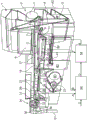
figure 1 shows a schematic overview of a known cigarette rod maker,
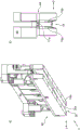
fig. 2 a) and b) show schematically a perspective single representation (a) and a cross-sectional representation (b) of a rod guide channel provided in the known cigarette rod maker of fig. 1,
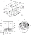
figures 3 a) to c) show schematic views of a first embodiment of a suction belt conveyor with microwave measuring means together with field distribution and radiation characteristics,
figures 4 a) to c) show a schematic representation, field characteristics and radiation characteristics of another embodiment of a suction belt conveyor with a microwave measuring mechanism,
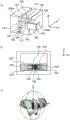
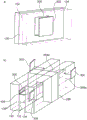
figures 5 a) to c) show another alternative embodiment, field and radiation characteristic in a schematic representation of a suction belt conveyor with a microwave measuring mechanism,
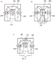
figures 6a to e) show schematic views of another alternative embodiment of a suction belt conveyor with a slotted rectangular conveyor together with detailed illustrations, field distributions and radiation characteristics,
figures 7 a) to c) show a schematic view of the steering together with the radiation characteristics for a corresponding slotted rectangular resonator,
figures 8 a) and b) show a schematic view of an absorption element for the channel side walls of a suction belt conveyor according to the invention,
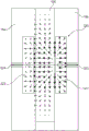
fig. 9) shows a schematic view of an embodiment of a suction belt conveyor with a capacitive measuring mechanism together with a field distribution.
In the figures, corresponding identical or similar elements and/or components are provided with the same reference numerals, so that a renewed description is correspondingly dispensed with.
Detailed Description
A known cigarette rod maker according to DE 102011082625 a1 is schematically shown in fig. 1, the construction and the operating principle of which are explained below.
From the sluice 1 the tobacco fibres (not shown in the drawings) are supplied in portions to a pre-distributor 2. A take-off roller 3 in the pre-dispenser 2 feeds tobacco fibres from the pre-dispenser 2 to a reserve container 4. A lifting conveyor 5 takes the tobacco fibres from the reserve container 4 and feeds a pile chute 6. The tube roll 7 takes out a substantially uniform flow of tobacco fibres from the stacking chute 6, which is beaten out of the tube roll 7 by a beater roll (Ausschlagwalze) 8 and thrown onto a dispersion cloth 9 rotating at a constant speed. A tobacco mat (Tabakvlies) is formed from the tobacco stream on the distribution 9. The tobacco mat is thrown into a sifting device 11, which essentially consists of an air curtain (luftvorhuang) that sifts out the larger or heavier tobacco fraction, while all other tobacco particles sink out of the air into a funnel 14, which consists of a tube roller 12 and a wall 13.
The tobacco fibers from the hopper 14 are conveyed by the tube roll 12 to the suction belt conveyor, more specifically into the strand guide channel 16 and there are thrown against the lower branch of the air-permeable, continuously rotating suction belt 17, which is loaded with underpressure from its back side and forms the bottom of the strand guide channel 16, from where the tobacco fibers are shaken off a tobacco fiber cake (tabakfaserkuche) in the form of a strand, which is thereby held on the lower branch of the suction belt 17 by means of the air sucked into the underpressure chamber 18. The tobacco fibre cake shaken or deposited therein is conveyed along the rod guide channel 16 as a rod in a suspended manner by the rotating suction belt 17. The lower branch of the suction belt 17 extends through the rod guide channel 16 from its beginning, where the rod-forming zone is located, in the embodiment shown, up to a trimming device (Egalisator) or trimmer 19 for removing excess tobacco fibres.
The tobacco rod thus formed is then placed on the synchronously guided cigarette paper band 21. The cigarette paper strip 21 is pulled off the bobbin 22, guided by a pressing mechanism 23 and put on a driven format belt (format band) 24. The Format belt 24 conveys the tobacco rod together with the cigarette paper strip 21 through the Format mechanism (Format) 26, in which the cigarette paper strip 21 is folded around the tobacco rod so that only a narrow edge also projects, which is glued by a gluing device, not shown, in a known manner. The bond seam thus formed is then closed and dried by a double seam panel (tandemnatpl ä tte) 27.
The cigarette rod 28 thus formed is passed through a measuring instrument 29 and subsequently cut by a cutter device 31 into double-length cigarettes 32. The double cigarettes 32 are transferred by a transfer device 34 with controlled arms onto a take-up roller 36 of a filter assembly machine 37, and are divided into individual cigarettes by a circular cutter on a cutting roller 38 of the filter assembly machine.
The conveyor belts 39, 41 convey the excess tobacco fibers separated by the trimming device 19 into a container 42 arranged below the storage container 4, from which they are removed again by the lifting conveyor 5 as returned tobacco.
The known strand guide channel 16 from DE 102011082625 a1 is shown in fig. 2 a) and 2 b) as individual parts with additional details.
The assembly comprising the strip guide channel 16 has a frame 46 by means of which this assembly is arranged in the machine shown in fig. 1. The strip guide channel 16 is open downward and has two lateral side walls 16a, 16b spaced apart from each other. Fig. 2b also shows schematically in cross section the lower branch 17a of the continuously rotating suction belt 17 (fig. 1) which forms the bottom (above) of the strand guide channel 16. The cavity 16c and thus the cross section of the strip guide channel 16 are also delimited by the two lateral channel side walls 16a, 16b and the lower branch 17a of the suction strip 17. The spacing between the channel side walls 16a, 16b on both sides of the rod guide channel 16 determines the width of the rod-shaped tobacco cake shaken out in the cavity 16c of the rod guide channel 16.
In the example shown, at least one of the two lateral side walls 16a, 16b can be adjusted transversely to the strip conveying direction according to the arrow X shown in fig. 2 a), which is schematically indicated in fig. 2 a) and 2 b) by a double arrow Y. By means of this adjustability of at least one of the two- sided side walls 16a, 16b, the distance of the two-sided side walls from one another and thus the clear width of the cavity 16c of the rod guide channel 16 can be varied, which also causes a corresponding variation in the width of the rod-shaped tobacco cake shaken out in the cavity 16c of the rod guide channel 16. For a given cross-sectional area of the rod-shaped tobacco cake shaken out in the cavity 16c of the rod guide channel 16, the variation in the width also has an influence on the stack height.
The lateral side walls 16a, 16b are adjusted by means of a drive 48, which drive 48 is actuated by a subsequent adjustment in which the distance between the two side channel side walls 16a, 16b or the clear width of the cavity 16c of the strand guide channel 16 forms an adjustment variable.
The already previous measuring device 29 is preferably designed to: the cross section, ovality or roundness and/or the density of the cigarette rod 28 and/or the weight of the cigarette 32 and/or the weight of the cigarette rod 28 per length unit and/or the degree of filling of the fibers in the cigarette rod 28 and/or in the cigarette 32 are detected and a corresponding output signal a is emitted. The output signal a is transmitted to the regulator 50. As can be seen schematically in fig. 1, a spacing sensor 52 is arranged on the rod guide channel 16, which spacing sensor detects the stack height of the rod-shaped tobacco cakes in the rod guide channel 16 and transmits a corresponding output signal B to the controller 50. The interval sensor 52 is disposed upstream of the dresser 19.
A further spacing sensor 56 is also arranged on the strand guide channel 16, with the aid of which the actual value of the respective clear spacing between the two lateral side walls 16a, 16b for the strand guide channel 16 and thus the width of the cavity 16c of the strand guide channel is detected and a corresponding signal F is transmitted to the adjustment mechanism 54. The controller 50 processes a target value signal C as a further input variable, by means of which a corresponding target value is predefined for one or more parameters to be controlled. These three signals A, B and C are processed in the regulator 50, which produces the resulting output signal D for actuating the downstream adjusting mechanism 54 accordingly.
Fig. 3 shows schematically, in a cut-away view, a suction belt conveyor according to a first exemplary embodiment of the invention, together with coaxial resonators 206, 207 inserted into the channel side walls 102, 104. These channel sidewalls can, but need not, be configured like the channel sidewalls 16a, 16b from fig. 2. Preferably, they are solid on the outside of the microwave measuring device.
A section through the strand guide path 100 is shown, wherein the strand transport direction 108 or the transport path 108 is indicated by an arrow. Between the channel side walls 102, 104, a suction belt 106 extends, which moves in the strip transport direction (arrow) and on which material is shaken up to a filling level 112, which is also the filling depth because it is shaken from below. Above the suction belt 106, a cover 110 is arranged, which upwardly limits the radiation of the microwave measurement field from the coaxial resonators 206, 207. In the schematic illustration, the rear channel side wall 102 is shown solid and the front channel side wall 104 is shown semi-transparently. The cover 110 is also integral per se and is not formed of two halves as shown in the schematic view of fig. 3 a) for the sake of clarity only.
The coaxial resonators 206, 207 of the microwave measuring device 200 each have a resonator cavity 202, 203, as can be clearly seen in fig. 3 b). Concentrically arranged in the resonator cavities 202, 203 are coaxial antennas 208, 209, respectively. The resonator cavities 202, 203 are open with openings 204, 205 to the guide channel 100, so that an electromagnetic microwave field, which is depicted by an arrow, penetrates into the guide channel 100.
A coordinate system is shown in each case not only in fig. 3 a) but also in fig. 3 b), in which the Z direction coincides with the transport path 108, the X direction is perpendicular to the Z axis in the horizontal direction and the Y direction is perpendicular to the Z axis in the vertical direction. The coaxial resonators 206, 207 are preferably lambda/4-coaxial resonators short-circuited at the ends. The maximum field strength occurs at the interface of the open ends of the respective coaxial resonators 206, 207 and decreases towards the center of the guide channel 100. The coaxial resonators 206, 207 have a radiation characteristic with a pronounced maximum, in particular along the Z-direction and along the X-direction.
Fig. 4 schematically shows an alternative exemplary embodiment according to the present invention. In contrast to the microwave measuring device 200 from fig. 3, the microwave measuring device 220 in fig. 4 a) and 4 b) is of symmetrical design with two resonator cavities 222, 223 which are rectangular in cross section and which open out in each case with an opening 224, 225 toward the guide channel 100. The extension of the resonator cavities 222, 223 in the direction of the conveying path 108 is significantly greater than the extension transverse to the conveying path, thus resulting in a predominantly Y component (E)y) Of the electric field of (a). The respective antenna 228, 229 penetrates into the resonator cavities 222, 223 from below in the vertical direction for generating a microwave field with a predominant Y component.
Said EyThe field strength distribution of the field components is shown in fig. 4 b). A good penetration of the guide channel 100 is shown. The vertical size of the resonator cavities 222, 223 is significantly smaller than half the wavelength of the used microwave measuring field between 4 and 6 GHz and larger than half the wavelength along the strip direction, so that a Mode (Mode), the field component of which in the Y direction can propagate perpendicular to the strip direction (Z direction), is obtained.
Also well recognizable in fig. 4 b) is the small spacing of the cover 110 relative to the suction strip 106. As the spacing of the cover 110 relative to the suction belt 106 increases, the resonant frequencies of the different excited modes approach one another, which has advantages in measurement technology. At the same time, however, an undesirable increase in the radiation is observed, so that a smaller cover spacing is desirable for the radiation.
Fig. 5 shows a schematic illustration of a further exemplary embodiment of a suction belt conveyor according to the invention with a microwave measuring device 240. As can be seen in perspective in fig. 5 a), two rectangular resonators 246, 247 are introduced into the channel side walls 102, 104, said resonators 242, 243 having rectangular resonator cavities 242, 243, which, as in the previous exemplary embodiment, are also aligned with one another and penetrate the guide channel 100 at the level of the material that is shaken off the suction belt 106. The rectangular resonator cavities 242, 243 now have a small extent in the strip direction which is smaller than half the wavelength of the microwave measuring field and a greater extent transversely to the strip direction in the vertical direction than half the wavelength.
As can be seen from fig. 5 b), the antennas 248, 249 are arranged with their antenna cables 248a, 249a symmetrically on both sides and project into the resonator cavities 242, 243 in the strip direction, i.e., in the Z direction. Exciting as a principal component having electric field lines (E) along the Z-directionz) Of (2) is performed. This field accordingly penetrates into the material in the guide channel 100 at the location of the openings 244, 245 facing the guide channel 100 and weakens towards the center. In general, the material is better penetrated by the electric field and the measurement window ratio along the Z-direction is at E of fig. 4yAnd is narrower in the resonator. However, the X-component of the electric field propagates in the channel side walls and, as can be seen in fig. 5 c), leads to stray radiation in the Z-direction depending on the radiation characteristics shown there.
Fig. 6 schematically shows a further exemplary embodiment with a microwave measuring device 260 having a slotted rectangular resonator 266 which extends in an inverted "U" shape around the guide channel 100 or the material below the suction belt 106 and is open downward for enabling a suction belt exchange. In the center, a slot-like opening 265 can be identified in fig. 6 a), which opening defines a measurement window which is narrow in the Z direction. The resonator cavity 262 of the slotted rectangular resonator 266 is schematically shown in a cross-sectional perspective in fig. 6 b). The cross section of the resonator cavity 262 in the Z direction is narrowed by means of a flange 272 toward the center, i.e., toward the material-carrying guide channel 100. Coupling-in portions 268a, 269a of the two antennas 268, 269 are shown, which extend into the resonator cavity 262 in the Z-direction. The microwave field in the resonator is formed throughout the U-shaped resonator.
Fig. 6 c) shows a cross section of the guide channel 100 and the slotted rectangular resonator 266 in the Y-Z plane, wherein the structure of the flange 272 can be clearly recognized, as also the antenna 269 protruding into the resonator cavity 266 in the Z direction and the arrangement of the antenna cable 269 outside the antenna.
Fig. 6 d) shows the field distribution of the electric field intensity in a front view with a cross-sectional plane in the center of the slot 265 for the resonator 266 according to fig. 6 a) to 6 c). The electric field decreases downwards and towards the centre in the shown configuration, but has the following advantages: it abuts the material and there is no structure-induced separation other than the window for microwave passage that prevents contamination of the resonator cavity 262. The sensor has the greatest sensitivity of all the microwave measuring mechanisms shown up to now.
The radiation shown in fig. 6 e) is maximal in the Z-direction and has the greatest radiation compared to the other embodiments.
In fig. 7a to 7 c), different configurations of the steering of the slotted rectangular resonator 266 are shown.
For a symmetric resonator, such as the slotted rectangular resonator 266, two propagating modes are excited: a "common mode" mode, for which the electric field lines (E) in the strip run (in particular) parallel to the strip and the magnetic field (H) surrounds both antennas; and a "push-pull" mode for which the electric field lines run between the antennas (in particular) orthogonal to the strips. The actual field distribution is finally a superposition of the two modes. If the incoupling antenna and the outcoupling antenna (coupling elements) are excited in common mode (fig. 7 a) or push-pull (fig. 7 b), the common mode or push-pull mode can be excited separately from one another. It has been shown that the push-pull mode is a mode that excites a so-called slab mode (plattenmode) in the channel sidewalls, which can propagate and radiate here as shown in fig. 7 b).
Fig. 7c shows an embodiment according to the invention, in which knowledge about the excitation in phase is advantageously used to reduce the radiation.
According to the exemplary embodiment shown, the two symmetrically arranged antennas 268, 269 are excited in phase (for example by simple signal splitting by means of a wilkinson divider) and effectively represent an electrode (coupling-in or coupling-out). The other electrode is embedded in the symmetry plane as shown in fig. 7 c). By means of this arrangement, no field distribution is excited which possesses a horizontal field component perpendicular to the strips, whereby radiation of microwave power into the environment can advantageously be at least partially suppressed.
An arrangement can also be considered which has no second electrode in the plane of symmetry. In this case, the resonator is operated in a reflective manner.
The slotted rectangular resonator 266 ranges in size from about 50 to 100 mm along the Z-direction, and also ranges in size from 50 to 100 mm along the Y-direction and about 70 mm along the X-direction. Other design dimensions can of course likewise be realized and taken into account in accordance with the invention.
One possible solution for reducing the radiation in the channel side walls, in particular due to the slab mode, is schematically shown in fig. 8 a), 8 b). Fig. 8 a) shows a schematic sectional illustration of a guide channel 100 with channel side walls 102, 104 into which absorbing elements 300, 302 of a material with a complex dielectric constant, such as a microwave-absorbing rubber material, a foam material or the like, are inserted opposite one another. These absorbing elements take power away from the radiated microwave field so that the external radiation is reduced. Fig. 8 b) shows the arrangement of such absorbing elements 300, 302, 304, 306 upstream and downstream of the slotted rectangular resonators 266 in the channel sidewalls 102, 104. The respective absorber elements 300 to 306 can, for example, be embedded in the channel side walls 102, 104 in the propagation direction, for this purpose, in specially provided cavities. The attenuation effect obtained increases with the size and layer thickness of the absorbing material. In the case of two laterally arranged 3 × 3 cm layers, the fundamental mode (Grundmode) of the TEM-plate mode can be attenuated by more than 10 dB along the propagation direction.
Fig. 9) shows a top view of the suction belt conveyor according to the invention with the strip guide channel 100 defined by the channel side walls 16a, 16b and the capacitance measuring device 320.
The measuring means of the capacitance comprise two cutouts (cavities) 321, 322 arranged opposite one another in the channel side walls 16a, 16b, which are filled with air or a dielectric. Each of the hollow portions is embedded with an electrode 323, 324. As can be seen from fig. 9, the capacitance measuring mechanism is similar in structure to a plate capacitor.
The effective measurement window is determined by the field lines shown by the arrows in fig. 9). These field lines also determine the actual effective measured capacitance. The remaining field lines should be assigned to stray capacitances.
All the mentioned features, the features which can be seen from the drawings only and also the individual features which are disclosed in combination with one another are also considered to be features which are essential to the invention both individually and in combination. The embodiments according to the invention can be realized by individual features or combinations of features. Features identified as "especially" or "preferred" within the scope of the invention should be understood as optional features.
List of reference numerals:
1 sluice gate
2 Pre-distributor
3 Material taking roller
4 storage container
5 lifting conveyor
6 Stacking chute
7-tube roller
8 beat out roller
9 dispersing cloth
11 screening mechanism
12-tube roller
13 wall body
14 funnel
16 guide channels
16a channel side wall
16b channel side wall
Cavity and cross section of 16c guide channels
17 suction belt
17a lower branch
18 negative pressure chamber
19 trimmer
21 cigarette paper tape
22 bobbin
23 pressing mechanism
24-specification belt
26-specification mechanism
27 two-seat joint board (Tandemnahtpl ä tte)
28 cigarette strip
29 measuring instrument
31 tool device
34 transfer device
36 receiving roller
37 filter assembly machine
38 cutting drum
39 conveyor belt
41 conveyer belt
42 container
46 frame
48 driving mechanism
50 regulator
52 space sensor
54 adjustment mechanism
56 space sensor
100 guide channels
102 channel side wall
104 channel side wall
106 suction belt
108 conveying path
110 cover
112 filling level
200 microwave measuring mechanism
202. 203 resonator cavity
204. 205 opening of the container
206. 207 coaxial resonator
208. 209 coaxial antenna
220 microwave measuring mechanism
222. 223 resonator cavity
224. 225 opening
226. 227 rectangular resonator
228. 229 aerial
240 microwave measuring mechanism
242. 243 resonator cavity
244. 245 opening
246. 247 rectangular resonator
248. 249 antenna
248a, 249a antenna cable
260 microwave measuring mechanism
262 resonator cavity
264. 265 opening
266 slotted rectangular resonator
268. 269 aerial
268a, 269a antenna cable
270 antenna
272 flange
300. 302 absorbent element
304. 306 absorbent element
320 capacitance measuring mechanism
321. 322 hollow part
323. 324 electrode
Claims (13)
1. Suction belt conveyor for conveying material for a rod maker of the tobacco processing industry, comprising at least one downwardly open rod guide channel (100) which is defined by two-sided channel side walls (102, 104) and a suction belt (106) along a conveying path (108), characterized in that at least one electromagnetic measuring device is integrated into the channel side walls (102, 104) of the suction belt conveyor at least one location along the conveying path (108) for determining properties of the conveyed material, wherein the measuring device is designed as a microwave measuring device with at least one resonator cavity, wherein the microwave measuring device comprises at least one measuring opening oriented toward the conveying path, wherein the at least one microwave measuring device comprises an inverted "U" -shaped slotted rectangular resonator (266), the rectangular resonator surrounds the strip guide channel (100) on three sides, wherein the slotted rectangular resonator (266) has three coupling-in and-out antennas (268, 269, 270), of which two antennas are arranged symmetrically on both sides of the strip guide channel (100) and the third antenna is arranged in the symmetry plane of the resonator cavity above the strip guide channel (100), wherein the two symmetrically arranged antennas are excited in phase and the third antenna is used as a coupling-out antenna, or the third antenna is excited and the two symmetrically arranged antennas are used as coupling-out antennas.
2. Suction belt conveyor according to claim 1, characterized in that the microwave measuring means comprise two coaxial resonators (206, 207) arranged opposite each other and incorporated in the side walls (102, 104) of the two channels.
3. Suction belt conveyor according to claim 1, characterized in that at least one microwave measuring device has in each case one resonator cavity with a rectangular cross section in the two opposite side walls of the channel, which resonator cavities with a rectangular cross section are arranged in alignment with one another on both sides of the strip guide channel (100).
4. Suction belt conveyor according to claim 1, characterized in that the slotted rectangular resonator (266) is included in addition to the resonator cavity.
5. A suction belt conveyor as claimed in claim 1, characterized in that one or both channel side walls (102, 104) have one or more microwave-absorbing planar bodies (300, 302, 304, 306) incorporated into one or both channel side walls (102, 104) downstream and/or upstream of the at least one resonator cavity along the conveying path (108) of the suction belt (106).
6. Suction belt conveyor according to claim 1, characterized in that power electronics and/or measuring electronics are arranged on the suction belt conveyor.
7. The suction belt conveyor of claim 1 wherein the material being conveyed is tobacco.
8. A rod making machine of the tobacco processing industry, comprising a suction belt conveyor according to any one of claims 1 to 7.
9. A rod making machine of the tobacco processing industry according to claim 8, wherein said rod making machine is a tobacco rod making machine.
10. Use of a microwave measuring device in a suction belt conveyor according to one of claims 1 to 7 in a rod maker of the tobacco processing industry for measuring material properties of tobacco material which is shaken off onto a suction belt (106) from below and which is held on the suction belt (106) by suction air.
11. Method for measuring material properties of a material strip of the tobacco processing industry, wherein the material is shaken off from below onto a suction belt (106) of a suction belt conveyor according to any one of claims 1 to 7 and is conveyed with the suction belt (106) along a conveying path (108) through a strip guide channel (100) of the suction belt conveyor, and the material properties of the material are measured in the strip guide channel (100) along the conveying path (108) by means of an electromagnetic measuring mechanism of the suction belt conveyor, wherein the measuring mechanism is configured as a microwave measuring mechanism with at least one resonator cavity, wherein the microwave measuring mechanism comprises at least one measuring opening oriented towards the conveying path.
12. The method of claim 11, wherein said resonating is performed as a transmission method.
13. The method of claim 11, wherein said strip of material is a tobacco strip.
Applications Claiming Priority (3)
| Application Number | Priority Date | Filing Date | Title |
|---|---|---|---|
| DE102015105353.5 | 2015-04-09 | ||
| DE102015105353.5A DE102015105353A1 (en) | 2015-04-09 | 2015-04-09 | Suction belt conveyor and rod machine of the tobacco processing industry, use and method for measuring material properties of a material strand of the tobacco processing industry |
| PCT/EP2016/057302 WO2016162292A1 (en) | 2015-04-09 | 2016-04-04 | Suction belt conveyor and strand-forming machine of the tobacco processing industry, and use and method for measuring material properties of a material strand of the tobacco processing industry |
Publications (2)
| Publication Number | Publication Date |
|---|---|
| CN107529813A CN107529813A (en) | 2018-01-02 |
| CN107529813B true CN107529813B (en) | 2021-10-01 |
Family
ID=55646612
Family Applications (1)
| Application Number | Title | Priority Date | Filing Date |
|---|---|---|---|
| CN201680020944.2A Active CN107529813B (en) | 2015-04-09 | 2016-04-04 | Suction belt conveyor and rod-making machine for the tobacco processing industry, method for measuring material properties of a material rod for the tobacco processing industry and use |
Country Status (8)
| Country | Link |
|---|---|
| US (1) | US11178901B2 (en) |
| EP (1) | EP3297461B1 (en) |
| JP (1) | JP7115854B2 (en) |
| KR (1) | KR102624354B1 (en) |
| CN (1) | CN107529813B (en) |
| DE (1) | DE102015105353A1 (en) |
| PL (1) | PL3297461T3 (en) |
| WO (1) | WO2016162292A1 (en) |
Families Citing this family (12)
| Publication number | Priority date | Publication date | Assignee | Title |
|---|---|---|---|---|
| DE102017123503A1 (en) * | 2017-10-10 | 2019-04-11 | Hauni Maschinenbau Gmbh | Method and system for producing rod-shaped products of the tobacco-processing industry |
| DE102018105111A1 (en) | 2018-03-06 | 2019-09-12 | Hauni Maschinenbau Gmbh | Saugbandförderer and strand machine of the tobacco processing industry and use of a measuring device in a suction belt conveyor a strand machine of the tobacco processing industry |
| IT201800003717A1 (en) * | 2018-03-19 | 2019-09-19 | Gd Spa | Transport and inspection station for a semi-finished product of the tobacco industry |
| DE102018116533A1 (en) * | 2018-07-09 | 2020-01-09 | Hauni Maschinenbau Gmbh | Measuring device for a suction belt conveyor and suction belt conveyor with a measuring device |
| EP3852557B1 (en) | 2018-09-21 | 2023-09-06 | G.D S.p.A. | Apparatus for the conveying and inspection of a semi-finished product of the tobacco industry |
| WO2020058871A1 (en) * | 2018-09-21 | 2020-03-26 | G.D S.P.A. | Electromagnetic detector for detecting properties of products of the tobacco industry |
| CH715607A1 (en) * | 2018-12-03 | 2020-06-15 | Koch Roger | Cigarette machine and process for making cigarettes. |
| DE202019103894U1 (en) | 2019-07-15 | 2019-09-23 | Tews Elektronik Gmbh & Co. Kg | Cigarette machine with a suction belt conveyor |
| RU2736959C2 (en) * | 2019-12-25 | 2020-11-23 | Хауни Машиненбау Гмбх | Measuring device for vacuum belt conveyor and vacuum belt conveyor with measuring device |
| CN112089084B (en) * | 2020-09-30 | 2024-08-09 | 太原科技大学 | Tobacco loosening vibration unit, tobacco discharging device and production line |
| CN115626419B (en) * | 2022-11-01 | 2024-02-20 | 邳州市新世界木业有限公司 | Woodworking machinery conveyer belt |
| DE102023125584A1 (en) | 2023-09-21 | 2025-03-27 | Körber Technologies Gmbh | Device and method for producing a rod for the tobacco processing industry |
Citations (3)
| Publication number | Priority date | Publication date | Assignee | Title |
|---|---|---|---|---|
| US4805641A (en) * | 1985-07-31 | 1989-02-21 | Korber Ag | Method and apparatus for ascertaining the density of wrapped tobacco fillers and the like |
| CN1052150C (en) * | 1995-07-14 | 2000-05-10 | 豪尼机械制造股份公司 | Apparatus for ascertaining complex dielectric constant of tobacco |
| CN101088008A (en) * | 2004-12-22 | 2007-12-12 | 豪尼机械制造股份公司 | Measuring device and method for determining a dielectric property, particularly humidity and/or density, of a product |
Family Cites Families (23)
| Publication number | Priority date | Publication date | Assignee | Title |
|---|---|---|---|---|
| DE3207124A1 (en) * | 1981-03-21 | 1982-09-30 | Hauni-Werke Körber & Co KG, 2050 Hamburg | Method and machine for producing rod-shaped smoking articles |
| US4474190A (en) | 1981-03-21 | 1984-10-02 | Hauni-Werke Korber & Co. Kg | Method and apparatus for regulating the operation of machines for the production of cigarettes or the like |
| US4538453A (en) * | 1982-03-27 | 1985-09-03 | Molins Plc | Method and apparatus for determining the mass and moisture content of tobacco |
| JPS60234575A (en) | 1984-05-08 | 1985-11-21 | 日本たばこ産業株式会社 | Content tobacco amount controller of cigarette producing machine |
| DE3613957C1 (en) | 1986-04-24 | 1987-06-25 | Bat Cigarettenfab Gmbh | Method and device for regulating at least two of the physical properties of a strand made of smokable material which are decisive for the quality of the finished product |
| DE3705576A1 (en) * | 1987-02-21 | 1988-09-01 | Hauni Werke Koerber & Co Kg | METHOD AND ARRANGEMENT FOR FORMING A STRAND OF TOBACCO |
| DE3725364A1 (en) * | 1987-07-31 | 1989-02-09 | Hauni Werke Koerber & Co Kg | METHOD AND ARRANGEMENT FOR MAKING A STRAND OF FIBERS OF TOBACCO OR ANOTHER SMOKEABLE MATERIAL |
| DE3725366A1 (en) | 1987-07-31 | 1989-02-09 | Hauni Werke Koerber & Co Kg | DEVICE FOR MEASURING THE DENSITY OF A STRING OF TOBACCO |
| CN1052150A (en) | 1989-11-30 | 1991-06-12 | 鞍山钢铁公司 | A low alloy sulfuric acid dew point corrosion resistant steel |
| DE4004119A1 (en) | 1990-02-10 | 1991-08-14 | Tews Elektronik Dipl Ing Manfr | METHOD FOR MEASURING THE HUMIDITY OF A MEASUREMENT WITH THE AID OF MICROWAVES AND DEVICE FOR IMPLEMENTING THE METHOD |
| AU2530495A (en) * | 1994-05-19 | 1995-12-18 | Molins Plc | Cigarette manufacture |
| JPH10325813A (en) * | 1997-05-23 | 1998-12-08 | Matsushita Electric Works Ltd | Microwave moisture meter |
| DE29716639U1 (en) | 1997-09-16 | 1999-01-21 | Tews Elektronik, 22459 Hamburg | Microwave stray field sensor for moisture and / or density measurement |
| DE19825592A1 (en) | 1998-06-09 | 1999-12-16 | Focke & Co | Method and device for determining the density of tobacco |
| JPH11346747A (en) * | 1998-06-12 | 1999-12-21 | Japan Tobacco Inc | Device for winding up tobacco |
| SE9803850L (en) | 1998-11-11 | 2000-05-12 | Kildal Antenna Consulting Ab | Dielectric microwave sensor |
| DE10112499B4 (en) | 2001-03-15 | 2010-08-19 | Hauni Maschinenbau Ag | Resonator device, in particular Mikrowellenresonatoreinrichtung |
| DE10117081A1 (en) | 2001-04-06 | 2002-10-10 | Hauni Maschinenbau Ag | Device and method for generating a statement about the property (s) of a fiber strand |
| TWI357425B (en) | 2003-09-09 | 2012-02-01 | Laird Technologies Inc | Microwave-absorbing form-in-place paste |
| DE202005001756U1 (en) * | 2004-02-12 | 2005-05-04 | Trützschler GmbH & Co KG | Microwave sensor for measuring a dielectric property of a product |
| DE202007018481U1 (en) | 2007-08-28 | 2008-09-11 | Tews Elektronik Dipl.-Ing. Manfred Tews | Device for measuring a moisture value of dielectric substances |
| DE102011082625A1 (en) | 2011-09-13 | 2013-03-14 | Hauni Maschinenbau Ag | Control device for controlling at least one parameter of an article of the tobacco processing industry |
| DE102013213936A1 (en) | 2013-07-16 | 2015-01-22 | Hauni Maschinenbau Ag | Arrangement and method for checking rod-shaped articles of the tobacco-processing industry |
-
2015
- 2015-04-09 DE DE102015105353.5A patent/DE102015105353A1/en active Pending
-
2016
- 2016-04-04 WO PCT/EP2016/057302 patent/WO2016162292A1/en unknown
- 2016-04-04 JP JP2017552801A patent/JP7115854B2/en active Active
- 2016-04-04 KR KR1020177032194A patent/KR102624354B1/en active Active
- 2016-04-04 CN CN201680020944.2A patent/CN107529813B/en active Active
- 2016-04-04 EP EP16713474.1A patent/EP3297461B1/en active Active
- 2016-04-04 PL PL16713474.1T patent/PL3297461T3/en unknown
-
2017
- 2017-10-06 US US15/726,926 patent/US11178901B2/en active Active
Patent Citations (3)
| Publication number | Priority date | Publication date | Assignee | Title |
|---|---|---|---|---|
| US4805641A (en) * | 1985-07-31 | 1989-02-21 | Korber Ag | Method and apparatus for ascertaining the density of wrapped tobacco fillers and the like |
| CN1052150C (en) * | 1995-07-14 | 2000-05-10 | 豪尼机械制造股份公司 | Apparatus for ascertaining complex dielectric constant of tobacco |
| CN101088008A (en) * | 2004-12-22 | 2007-12-12 | 豪尼机械制造股份公司 | Measuring device and method for determining a dielectric property, particularly humidity and/or density, of a product |
Also Published As
| Publication number | Publication date |
|---|---|
| JP7115854B2 (en) | 2022-08-09 |
| PL3297461T3 (en) | 2023-01-16 |
| KR102624354B1 (en) | 2024-01-11 |
| US11178901B2 (en) | 2021-11-23 |
| DE102015105353A1 (en) | 2016-10-13 |
| WO2016162292A1 (en) | 2016-10-13 |
| JP2018511330A (en) | 2018-04-26 |
| US20180027868A1 (en) | 2018-02-01 |
| KR20170134696A (en) | 2017-12-06 |
| EP3297461B1 (en) | 2022-08-24 |
| EP3297461A1 (en) | 2018-03-28 |
| CN107529813A (en) | 2018-01-02 |
Similar Documents
| Publication | Publication Date | Title |
|---|---|---|
| CN107529813B (en) | Suction belt conveyor and rod-making machine for the tobacco processing industry, method for measuring material properties of a material rod for the tobacco processing industry and use | |
| JP4477281B2 (en) | Method for inspecting production articles | |
| EP0935136B1 (en) | Method for determining the moisture content of a bulk material | |
| JP4679034B2 (en) | Method and apparatus for detecting and selecting foreign matter in cigarettes | |
| JPH07308179A (en) | Method and device for determining density of fiber material stream on cigaret producing machine | |
| CN101512328A (en) | A re-entrant microwave resonator for detecting a characteristic like humidity, density or presence of foreign substances in a fibrous material like cigarettes | |
| US7800378B2 (en) | Microwave resonator for or on a textile machine, especially a card, draw frame, combing machine or the like | |
| JPH0928365A (en) | Device that measures complex permittivity of tobacco | |
| GB2489587A (en) | Method and system for producing an endless filter rod | |
| US7068048B2 (en) | Microwave sensor for measuring a dielectric property of a product | |
| AU1590999A (en) | Determining moisture content by using microwaves phase and attentuation | |
| KR20190039132A (en) | A measuring device and method for detecting an electrically conductive element of a product, | |
| CN106690407A (en) | Apparatus, machine, method and use for checking cigarette head quality | |
| JP2000028552A (en) | Method and device for measuring density of substance with free water correction | |
| US20080211516A1 (en) | Method and Measuring Instrument for Measuring Water Content | |
| CN107438517A (en) | System for manufacturing corrugated cardboard width | |
| US6897659B2 (en) | Device for testing the quality of rope-like materials | |
| KR102786457B1 (en) | Station for transport and inspection of semi-finished products of the tobacco industry | |
| CN113766838B (en) | Method and apparatus for manufacturing cylindrical heating type smoking article | |
| CN114126423B (en) | Cigarette machine with adsorption belt conveyor | |
| RU2736959C2 (en) | Measuring device for vacuum belt conveyor and vacuum belt conveyor with measuring device | |
| EP4533073A1 (en) | Electromagnetic detector for detecting properties of products of the tobacco industry | |
| CN112740022A (en) | Electromagnetic detector for detecting properties of products of the tobacco industry | |
| CH697758B1 (en) | Microwave sensor for measuring a dielectric property, in particular the density and / or humidity, a product. |
Legal Events
| Date | Code | Title | Description |
|---|---|---|---|
| PB01 | Publication | ||
| PB01 | Publication | ||
| SE01 | Entry into force of request for substantive examination | ||
| SE01 | Entry into force of request for substantive examination | ||
| GR01 | Patent grant | ||
| GR01 | Patent grant | ||
| CP01 | Change in the name or title of a patent holder | ||
| CP01 | Change in the name or title of a patent holder |
Address after: Hamburg, Germany Patentee after: Kolber Technology Co.,Ltd. Address before: Hamburg, Germany Patentee before: HAUNI MASCHINENBAU GmbH |