CN1075018C - Pallet for collapsible container/pallet system - Google Patents
Pallet for collapsible container/pallet system Download PDFInfo
- Publication number
- CN1075018C CN1075018C CN97193549A CN97193549A CN1075018C CN 1075018 C CN1075018 C CN 1075018C CN 97193549 A CN97193549 A CN 97193549A CN 97193549 A CN97193549 A CN 97193549A CN 1075018 C CN1075018 C CN 1075018C
- Authority
- CN
- China
- Prior art keywords
- pallet
- top panel
- transverse plate
- rod member
- plastic pallet
- Prior art date
- Legal status (The legal status is an assumption and is not a legal conclusion. Google has not performed a legal analysis and makes no representation as to the accuracy of the status listed.)
- Expired - Fee Related
Links
Images


Classifications
-
- B—PERFORMING OPERATIONS; TRANSPORTING
- B65—CONVEYING; PACKING; STORING; HANDLING THIN OR FILAMENTARY MATERIAL
- B65D—CONTAINERS FOR STORAGE OR TRANSPORT OF ARTICLES OR MATERIALS, e.g. BAGS, BARRELS, BOTTLES, BOXES, CANS, CARTONS, CRATES, DRUMS, JARS, TANKS, HOPPERS, FORWARDING CONTAINERS; ACCESSORIES, CLOSURES, OR FITTINGS THEREFOR; PACKAGING ELEMENTS; PACKAGES
- B65D71/00—Bundles of articles held together by packaging elements for convenience of storage or transport, e.g. portable segregating carrier for plural receptacles such as beer cans or pop bottles; Bales of material
- B65D71/0088—Palletisable loads, i.e. loads intended to be transported by means of a fork-lift truck
- B65D71/0092—Palletisable loads, i.e. loads intended to be transported by means of a fork-lift truck provided with one or more rigid supports, at least one dimension of the supports corresponding to a dimension of the load, e.g. skids
- B65D71/0096—Palletisable loads, i.e. loads intended to be transported by means of a fork-lift truck provided with one or more rigid supports, at least one dimension of the supports corresponding to a dimension of the load, e.g. skids the dimensions of the supports corresponding to the periphery of the load, e.g. pallets
-
- B—PERFORMING OPERATIONS; TRANSPORTING
- B65—CONVEYING; PACKING; STORING; HANDLING THIN OR FILAMENTARY MATERIAL
- B65D—CONTAINERS FOR STORAGE OR TRANSPORT OF ARTICLES OR MATERIALS, e.g. BAGS, BARRELS, BOTTLES, BOXES, CANS, CARTONS, CRATES, DRUMS, JARS, TANKS, HOPPERS, FORWARDING CONTAINERS; ACCESSORIES, CLOSURES, OR FITTINGS THEREFOR; PACKAGING ELEMENTS; PACKAGES
- B65D19/00—Pallets or like platforms, with or without side walls, for supporting loads to be lifted or lowered
- B65D19/0004—Rigid pallets without side walls
- B65D19/0053—Rigid pallets without side walls the load supporting surface being made of more than one element
- B65D19/0055—Rigid pallets without side walls the load supporting surface being made of more than one element forming a continuous plane contact surface
- B65D19/0067—Rigid pallets without side walls the load supporting surface being made of more than one element forming a continuous plane contact surface the base surface being made of more than one element
- B65D19/0069—Rigid pallets without side walls the load supporting surface being made of more than one element forming a continuous plane contact surface the base surface being made of more than one element forming a continuous plane contact surface
-
- B—PERFORMING OPERATIONS; TRANSPORTING
- B65—CONVEYING; PACKING; STORING; HANDLING THIN OR FILAMENTARY MATERIAL
- B65D—CONTAINERS FOR STORAGE OR TRANSPORT OF ARTICLES OR MATERIALS, e.g. BAGS, BARRELS, BOTTLES, BOXES, CANS, CARTONS, CRATES, DRUMS, JARS, TANKS, HOPPERS, FORWARDING CONTAINERS; ACCESSORIES, CLOSURES, OR FITTINGS THEREFOR; PACKAGING ELEMENTS; PACKAGES
- B65D19/00—Pallets or like platforms, with or without side walls, for supporting loads to be lifted or lowered
- B65D19/38—Details or accessories
- B65D19/44—Elements or devices for locating articles on platforms
-
- B—PERFORMING OPERATIONS; TRANSPORTING
- B65—CONVEYING; PACKING; STORING; HANDLING THIN OR FILAMENTARY MATERIAL
- B65D—CONTAINERS FOR STORAGE OR TRANSPORT OF ARTICLES OR MATERIALS, e.g. BAGS, BARRELS, BOTTLES, BOXES, CANS, CARTONS, CRATES, DRUMS, JARS, TANKS, HOPPERS, FORWARDING CONTAINERS; ACCESSORIES, CLOSURES, OR FITTINGS THEREFOR; PACKAGING ELEMENTS; PACKAGES
- B65D2519/00—Pallets or like platforms, with or without side walls, for supporting loads to be lifted or lowered
- B65D2519/00004—Details relating to pallets
- B65D2519/00009—Materials
- B65D2519/00014—Materials for the load supporting surface
- B65D2519/00034—Plastic
-
- B—PERFORMING OPERATIONS; TRANSPORTING
- B65—CONVEYING; PACKING; STORING; HANDLING THIN OR FILAMENTARY MATERIAL
- B65D—CONTAINERS FOR STORAGE OR TRANSPORT OF ARTICLES OR MATERIALS, e.g. BAGS, BARRELS, BOTTLES, BOXES, CANS, CARTONS, CRATES, DRUMS, JARS, TANKS, HOPPERS, FORWARDING CONTAINERS; ACCESSORIES, CLOSURES, OR FITTINGS THEREFOR; PACKAGING ELEMENTS; PACKAGES
- B65D2519/00—Pallets or like platforms, with or without side walls, for supporting loads to be lifted or lowered
- B65D2519/00004—Details relating to pallets
- B65D2519/00009—Materials
- B65D2519/00049—Materials for the base surface
- B65D2519/00069—Plastic
-
- B—PERFORMING OPERATIONS; TRANSPORTING
- B65—CONVEYING; PACKING; STORING; HANDLING THIN OR FILAMENTARY MATERIAL
- B65D—CONTAINERS FOR STORAGE OR TRANSPORT OF ARTICLES OR MATERIALS, e.g. BAGS, BARRELS, BOTTLES, BOXES, CANS, CARTONS, CRATES, DRUMS, JARS, TANKS, HOPPERS, FORWARDING CONTAINERS; ACCESSORIES, CLOSURES, OR FITTINGS THEREFOR; PACKAGING ELEMENTS; PACKAGES
- B65D2519/00—Pallets or like platforms, with or without side walls, for supporting loads to be lifted or lowered
- B65D2519/00004—Details relating to pallets
- B65D2519/00009—Materials
- B65D2519/00084—Materials for the non-integral separating spacer
- B65D2519/00104—Plastic
-
- B—PERFORMING OPERATIONS; TRANSPORTING
- B65—CONVEYING; PACKING; STORING; HANDLING THIN OR FILAMENTARY MATERIAL
- B65D—CONTAINERS FOR STORAGE OR TRANSPORT OF ARTICLES OR MATERIALS, e.g. BAGS, BARRELS, BOTTLES, BOXES, CANS, CARTONS, CRATES, DRUMS, JARS, TANKS, HOPPERS, FORWARDING CONTAINERS; ACCESSORIES, CLOSURES, OR FITTINGS THEREFOR; PACKAGING ELEMENTS; PACKAGES
- B65D2519/00—Pallets or like platforms, with or without side walls, for supporting loads to be lifted or lowered
- B65D2519/00004—Details relating to pallets
- B65D2519/00258—Overall construction
- B65D2519/00283—Overall construction of the load supporting surface
- B65D2519/00293—Overall construction of the load supporting surface made of more than one piece
-
- B—PERFORMING OPERATIONS; TRANSPORTING
- B65—CONVEYING; PACKING; STORING; HANDLING THIN OR FILAMENTARY MATERIAL
- B65D—CONTAINERS FOR STORAGE OR TRANSPORT OF ARTICLES OR MATERIALS, e.g. BAGS, BARRELS, BOTTLES, BOXES, CANS, CARTONS, CRATES, DRUMS, JARS, TANKS, HOPPERS, FORWARDING CONTAINERS; ACCESSORIES, CLOSURES, OR FITTINGS THEREFOR; PACKAGING ELEMENTS; PACKAGES
- B65D2519/00—Pallets or like platforms, with or without side walls, for supporting loads to be lifted or lowered
- B65D2519/00004—Details relating to pallets
- B65D2519/00258—Overall construction
- B65D2519/00283—Overall construction of the load supporting surface
- B65D2519/00298—Overall construction of the load supporting surface skeleton type
-
- B—PERFORMING OPERATIONS; TRANSPORTING
- B65—CONVEYING; PACKING; STORING; HANDLING THIN OR FILAMENTARY MATERIAL
- B65D—CONTAINERS FOR STORAGE OR TRANSPORT OF ARTICLES OR MATERIALS, e.g. BAGS, BARRELS, BOTTLES, BOXES, CANS, CARTONS, CRATES, DRUMS, JARS, TANKS, HOPPERS, FORWARDING CONTAINERS; ACCESSORIES, CLOSURES, OR FITTINGS THEREFOR; PACKAGING ELEMENTS; PACKAGES
- B65D2519/00—Pallets or like platforms, with or without side walls, for supporting loads to be lifted or lowered
- B65D2519/00004—Details relating to pallets
- B65D2519/00258—Overall construction
- B65D2519/00313—Overall construction of the base surface
- B65D2519/00323—Overall construction of the base surface made of more than one piece
-
- B—PERFORMING OPERATIONS; TRANSPORTING
- B65—CONVEYING; PACKING; STORING; HANDLING THIN OR FILAMENTARY MATERIAL
- B65D—CONTAINERS FOR STORAGE OR TRANSPORT OF ARTICLES OR MATERIALS, e.g. BAGS, BARRELS, BOTTLES, BOXES, CANS, CARTONS, CRATES, DRUMS, JARS, TANKS, HOPPERS, FORWARDING CONTAINERS; ACCESSORIES, CLOSURES, OR FITTINGS THEREFOR; PACKAGING ELEMENTS; PACKAGES
- B65D2519/00—Pallets or like platforms, with or without side walls, for supporting loads to be lifted or lowered
- B65D2519/00004—Details relating to pallets
- B65D2519/00258—Overall construction
- B65D2519/00313—Overall construction of the base surface
- B65D2519/00328—Overall construction of the base surface shape of the contact surface of the base
- B65D2519/00333—Overall construction of the base surface shape of the contact surface of the base contact surface having a stringer-like shape
-
- B—PERFORMING OPERATIONS; TRANSPORTING
- B65—CONVEYING; PACKING; STORING; HANDLING THIN OR FILAMENTARY MATERIAL
- B65D—CONTAINERS FOR STORAGE OR TRANSPORT OF ARTICLES OR MATERIALS, e.g. BAGS, BARRELS, BOTTLES, BOXES, CANS, CARTONS, CRATES, DRUMS, JARS, TANKS, HOPPERS, FORWARDING CONTAINERS; ACCESSORIES, CLOSURES, OR FITTINGS THEREFOR; PACKAGING ELEMENTS; PACKAGES
- B65D2519/00—Pallets or like platforms, with or without side walls, for supporting loads to be lifted or lowered
- B65D2519/00004—Details relating to pallets
- B65D2519/00258—Overall construction
- B65D2519/00368—Overall construction of the non-integral separating spacer
- B65D2519/00373—Overall construction of the non-integral separating spacer whereby at least one spacer is made of one piece
-
- B—PERFORMING OPERATIONS; TRANSPORTING
- B65—CONVEYING; PACKING; STORING; HANDLING THIN OR FILAMENTARY MATERIAL
- B65D—CONTAINERS FOR STORAGE OR TRANSPORT OF ARTICLES OR MATERIALS, e.g. BAGS, BARRELS, BOTTLES, BOXES, CANS, CARTONS, CRATES, DRUMS, JARS, TANKS, HOPPERS, FORWARDING CONTAINERS; ACCESSORIES, CLOSURES, OR FITTINGS THEREFOR; PACKAGING ELEMENTS; PACKAGES
- B65D2519/00—Pallets or like platforms, with or without side walls, for supporting loads to be lifted or lowered
- B65D2519/00004—Details relating to pallets
- B65D2519/00547—Connections
- B65D2519/00552—Structures connecting the constitutive elements of the pallet to each other, i.e. load supporting surface, base surface and/or separate spacer
- B65D2519/00557—Structures connecting the constitutive elements of the pallet to each other, i.e. load supporting surface, base surface and/or separate spacer without separate auxiliary elements
- B65D2519/00562—Structures connecting the constitutive elements of the pallet to each other, i.e. load supporting surface, base surface and/or separate spacer without separate auxiliary elements chemical connection, e.g. glued, welded, sealed
-
- B—PERFORMING OPERATIONS; TRANSPORTING
- B65—CONVEYING; PACKING; STORING; HANDLING THIN OR FILAMENTARY MATERIAL
- B65D—CONTAINERS FOR STORAGE OR TRANSPORT OF ARTICLES OR MATERIALS, e.g. BAGS, BARRELS, BOTTLES, BOXES, CANS, CARTONS, CRATES, DRUMS, JARS, TANKS, HOPPERS, FORWARDING CONTAINERS; ACCESSORIES, CLOSURES, OR FITTINGS THEREFOR; PACKAGING ELEMENTS; PACKAGES
- B65D2571/00—Bundles of articles held together by packaging elements for convenience of storage or transport, e.g. portable segregating carrier for plural receptacles such as beer cans, pop bottles; Bales of material
- B65D2571/00006—Palletisable loads, i.e. loads intended to be transported by means of a fork-lift truck
- B65D2571/00055—Clapping elements, also placed on the side
-
- B—PERFORMING OPERATIONS; TRANSPORTING
- B65—CONVEYING; PACKING; STORING; HANDLING THIN OR FILAMENTARY MATERIAL
- B65D—CONTAINERS FOR STORAGE OR TRANSPORT OF ARTICLES OR MATERIALS, e.g. BAGS, BARRELS, BOTTLES, BOXES, CANS, CARTONS, CRATES, DRUMS, JARS, TANKS, HOPPERS, FORWARDING CONTAINERS; ACCESSORIES, CLOSURES, OR FITTINGS THEREFOR; PACKAGING ELEMENTS; PACKAGES
- B65D2571/00—Bundles of articles held together by packaging elements for convenience of storage or transport, e.g. portable segregating carrier for plural receptacles such as beer cans, pop bottles; Bales of material
- B65D2571/00006—Palletisable loads, i.e. loads intended to be transported by means of a fork-lift truck
- B65D2571/00111—Arrangements of flexible binders
- B65D2571/00117—Arrangements of flexible binders with protecting or supporting elements arranged between binder and articles or materials, e.g. for preventing chafing of binder
Abstract
The invention discloses three embodiments of a plastic pallet (11) and accompanying top frames. The parts of the pallets (11) and top frames are formed from extruded stock, and many such parts are made from the same or similar stock. In the basic aspects of the invention, all embodiments of the pallet (11) include top (19) and bottom (27) sections which are spaced from one another by spacer blocks (14) which are formed from a commom piece of plastic stock. Most desirably, each of these spacer blocks (14) is generally hollow with strengthening webbing (31) but is oriented relative to the top (19) and bottom (27) decks so that the latter close those opposed ends at which the hollow interior and webbing (31) otherwise would be exposed. The design is such that exposed ends of other parts of the pallet are similarly closed by other parts.
Description
Background of invention
The present invention relates to be used to load and unload, carry and store the pallet of cargo receptacle, particularly relate to the quite cheap plastic pallet structure of a kind of crash-resistant cost.
Plastic pallet is the product that occurs already.According to commercial point of view, the use of pallet is generally limited to container and goods moving in enclosure space, for example moves in the warehouse.A reason is that plastic pallet is quite expensive, and the manager need consider maintenance care usually.Another reason is that many plastic pallets generally all lack enough impregnabilityes, so that can not bear the situation about abusing that runs in daily use.In this case, nowadays most of plastic pallet is molded or vacuum forming is an integral member, perhaps by the component set-up of molded or vacuum forming.Though this integrated pallet can sustain situation about abusing usually, its manufacturing expense has increased the cost of plastic pallet greatly.And some pallet that constitutes by extruder member, (see U.S. Pat-3,878,796 and NBX Packaging Specialists of Wausau, the pallet that Wisconsin provides, its trade mark is called Enviro-board), general this pallet does not possess the advantage that adopts pressing method or adopt the product of parts interconnection technique manufacturing.
The applicant has developed reusable plastic container (seeing U.S. Pat-5,450,982), and has invented plastic pallet, particularly is applicable to the pallet of this container.The applicant has solved the many problems that are present in the plastic pallet in the process of development plastic pallet.
Summary of the invention
The invention provides a kind of in light weight, plastic pallet that cost is quite low, it has enough impregnabilityes in daily use.This firm and lightweight plastic pallet is by a plurality of discrete component set-ups, and these parts can only be made by a few plastics rod member, described plastic pallet comprises following discrete parts: the top panel part, it forms the surface of pallet, this surface is connected with the goods that is transferred, described tray surface comprises a plurality of transverse plates and a pair of boundary plank, and each described boundary plank seals an end of described transverse plate; The bottom panel part, the stayed surface of its contact pallet; With a plurality of intervals block, extension and fixing between described top panel partial sum bottom panel part partly separates described top panel partial sum bottom panel, forms passage between described top panel partial sum bottom panel part, picks up bar so that receive the inspection of pallet.
This pallet is made by the different parts and the part of extrusion forming.The major advantage of this pallet is that many parts can be replaced mutually, and are made by same plastics rod member.Its main achievement is that the cost of this plastic pallet is quite low.Though its low cost of manufacture but provides needed impregnability in daily use with the pallet of spline structure.This structure has also overcome the defective that occurs when making pallet.In addition, its structure makes by the welding process between the element, can produce failure-free, have the pallet of rugged construction.
Of the present invention main aspect, pallet of the present invention comprises top panel partial sum bottom panel part, by a plurality of intervals block top panel partial sum bottom panel partly is spaced from each other, described block is made by the plastics rod member of same material.Best, the interval block rod member of extruding has hollow interior, and there is strengthening web to support the outer wall of block, each block is provided with respect to top panel partial sum bottom panel part is directed, so that the opposed end that exposes its hollow interior and its web of partially enclosed those blocks of top panel partial sum bottom panel.Best, top panel partial sum bottom panel part is made by several crushed elements, and wherein subelement promptly can be used for making the top panel part and also can be used for making the bottom panel part.In addition, the structure of a plurality of elements is suitable for adopting easily firm and failure-free interconnection technique.
The principal character of pallet of the present invention is not only can be used to provide to use pallet more, and can be used to provide purpose-made pallet, and for example, a kind of structure is that when the container that is provided by above-mentioned patent was in erectility, such container and pallet cooperatively interacted; Another kind of structure is that when container was in folded state, this container and pallet cooperatively interacted.
Below by detailed description, can know other features and advantages of the present invention to the preferred embodiments of the present invention and its modification.
Brief description of drawings
The following accompanying drawing of reference:
Fig. 1 is the axonometric drawing of the preferred embodiment of pallet of the present invention;
Fig. 2 is the decomposing schematic representation of pallet shown in Figure 1;
Fig. 3 A is the boundary plank cross sectional drawing of the top panel parts of pallet shown in Figure 1;
Fig. 3 B is the partial schematic diagram boundary plank zone, that amplify that is surrounded by line 3B among Fig. 3 A, the typical structure of its expression energy drag device;
Fig. 3 C is the end view of the narrow transverse plate in the middle top panel parts embodiment illustrated in fig. 1:
Fig. 3 D is the end view of a transverse plate of the ratio broad in the middle top panel parts embodiment illustrated in fig. 1:
Fig. 3 E is the end view of the space block in embodiment illustrated in fig. 1;
Fig. 3 F is the end view that is similar to Fig. 3 C, and it represents the end face of a narrow transverse plate in the top frame assembly shown in Figure 5;
Fig. 3 G is the end view of the plate in the connection top frame assembly shown in Figure 5, and this plate is similar to the plate shown in Fig. 3 D:
Fig. 4 A is the axonometric drawing that is similar to an alternative embodiment of the invention of Fig. 1, wherein have can with the disclosed such container of U.S. Pat-5450982, interactional container interlocking tape;
Fig. 4 B is the amplification end view of the interlocking tape of pallet shown in Figure 4, and it represents the structure of this tape;
Fig. 5 is the partial isometric that is used for the top frame of the embodiment of the invention shown in Fig. 4 A;
Fig. 6 A is the front elevation that pallet shown in Figure 4 is equipped with container, and its expression is same as top frame shown in Figure 5.
Fig. 6 B is the lateral plan of Fig. 6 A illustrated embodiment;
Fig. 7 is the axonometric drawing of another embodiment of the present invention, and its expression has the container of a plurality of expansion;
Fig. 8 is the view similar to Fig. 7, the axonometric drawing that expression disassembles pallet shown in Figure 7 and the container that folds;
Fig. 9 is the axonometric drawing that is used for the top frame of pallet shown in Fig. 7 and 8;
Figure 10 is the front elevation that pallet is equipped with folding container shown in Fig. 7 and 8;
Figure 11 is the lateral plan of embodiment same as shown in Figure 10;
Figure 12 is the axonometric drawing of pallet shown in top frame shown in Figure 9 and Fig. 7 and 8, the mode that its expression top frame and pallet cooperatively interact;
Figure 13 is an axonometric drawing, and its assembly set of representing a plurality of pallet/top frame shown in Figure 12 is deposited in together, so that carry;
Figure 14 is the scheme drawing of extrusion line, and they can be provided for the needed shared rod member of the top frame shown in the pallet shown in shop drawings 1 and 4 and Fig. 5 and 9 respectively.
Detailed description of preferred embodiment
In order to meet the relevant regulations of patent law, provide following detailed.Obviously, for this professional those of ordinary skill, under the situation that does not break away from design of the present invention and scope, can make multiple variation and remodeling.
With reference to Fig. 1 and 2, common plastic pallet of the present invention is by code name 11 expressions.This pallet comprises top panel parts 12, and it has and is placed on the top surface that container on the pallet or other material cooperatively interact; With the bottom panel parts 13 that stayed surface cooperatively interacts, the ground or the floor of for example placing pallet; And a plurality of blocks 14, by these blocks 14 top panel parts 12 and bottom panel parts 13 are spaced from each other.As shown in Figure 1, the block 14 of location makes and form passage 16 between panel, so that bar is picked up in the fork lifter of reception routine or the inspection of analogue.In this structure, the frame element that forms bottom panel is provided with the inclined-plane of code name 17 expressions, so that make inspection pick up bar access passage 16 easily.
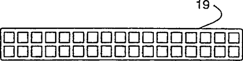
In more detail, though top panel partly has more than ten parts,, only need to provide three kinds of different extruding plastic rod members according to its structure.All these a plurality of parts can be made by these three kinds of rod members.That is, be used for illustrating the preferred embodiments of the present invention, comprising nine transverse bar member, adopting wherein six transverse bar member of same extruding rod member manufacturing, then making by another kind extruding rod member by other three transverse bar member of code name 19 expressions by code name 18 expressions.(as described below, the extruding rod member identical with transverse bar member 18 can be used for making a plurality of elements of bottom panel).
The top panel part also comprises a pair of boundary plank spaced apart from each other 21.Each boundary plank 21 L-shaped transversal surface, its one leg is adjacent and seal the open end of corresponding transverse bar member 18 and 19, its in addition one leg the first type surface of meeting stile is provided.
Lath is avoided extrudate simultaneously with connection mode connection side listrium reliably, for example avoids adopting clamping element.Can finish aforesaid operations simply by Vibration Welding.For this reason, as shown in Figure 3A, the surface 22 of each boundary plank has a plurality of Vibration Welding energy drag devices 23 that are provided with along its length direction.The fragmentary section views of in Fig. 3 B, having represented one of energy drag device 23 of amplifying.These energy drag devices make the surface 22 of boundary plank and the end of corresponding transverse plate carry out Vibration Welding easily.As everyone knows, vibrate by the surface that will bond together mutually and to obtain Vibration Welding, energy drag device 23 is as linear energy and material concentrator; Be beneficial to carry out Vibration Welding.
Though pallet of the present invention adopts Vibration Welding, this professional those of ordinary skill also can adopt the welding method of other types as can be known, and for example hot plate welding also is feasible.
As shown in Figure 3A, boundary plank has the lattice structure.The inside that is each boundary plank is hollow and has web, and it is similar to, and egg case or other extend between wall and upholder, can separate the packaging structure of individual articles.Such constructional feature is that the weight than solid construction alleviates greatly, and this boundary plank be configured with the total weight that helps alleviate support holder structure.Shown in Fig. 3 C and 3d, transverse plate 18 and 19 also has the lattice structure, and the outer wall at them is provided with reinforcing section as required, so also can expendable weight.
Can see that the structure of top panel is such, promptly transverse plate 18 and 19 open end are sealed by boundary plank.This is very important, because it can prevent that insect and foreign material from accumulating in the transverse plate.Also comprise boundary plank end cap 23 (Fig. 2), produce and the boundary plank similar problem so that avoid.The top panel part also comprises median plate 26, and it extends between the end of pallet, and perpendicular to transverse plate 18,19.Therefore median plate 26 is not fixed on the transverse plate 18,19, but is fixed on the interval block 14 that is in contact with it.
Also can adopt Vibration Welding that each long lath is fixed together.In this case, lath 27 and 27 ' the lattice structure that exposes of end as the energy drag device, so that carry out this Vibration Welding.
Adopting at interval as previously described, block 14 partly is separated from each other bottom panel and top panel.Each of these interval blocks 14 all has hollow rectangular configuration, and it comprises internal web, so that support the wall of block.Shown in Fig. 3 E, each interval block comprises internal web transverse wall 29, and it extends between the center line of each longwell of block, and a pair of mutual opposed chevron pointing web 31 is arranged, and respectively the relative central authorities than shortwall is connected to the part of longwell.
Each block 14 aligns with respect to panel, and promptly panel seals the relative end of each block, as shown in Figure 2.The web end also can be used as the energy drag device, is beneficial to adopt Vibration Welding that block is fixed on faceplate part.Block 14 is bonded to after the bottom panel, adopt heating and pressure method, the lath edge that pressurizes suitably from the outside of lath processes bevel edge 17.
Find out as above-mentioned, in a plurality of component set-up pallets, can constitute wherein most of parts by same extruding rod member.Because the structure of pallet, the open end of many parts are the parts sealings with other extrusion formings.Keep the end cap of minimum number, only need to provide end cap 23,24,28 to get final product.These end caps can injection mo(u)lding, owing to can make a plurality of pallets at one time, so that the die cost of each end cap can be maintained to is minimum.
Easy and the U.S. Pat-5,450 of pallet of the present invention, 912 disclosed plastic container match.Promptly by additional a little and revise and just can make basic pallet, so that provide purpose-made pallet for upright vessel or Foldable container.Fig. 4 A and 4B represent to be used for the purpose-made pallet of this upright vessel.Fig. 4 A and 4B show the basic pallet etcetera that is used for such upright vessel.Fig. 5 represents top frame, will be discussed below.Fig. 6 A, 6B represent to be used for the pallet of stacking and upright vessel.
Have container lath guide 31 in the purpose-made pallet shown in Fig. 4 A 30, edge with each container is adjacent respectively for it.As shown in the figure, two guides also can lean against the edge setting that is parallel to the lath guide privately along the central authorities of pallet.Therefore can see and on each pallet, can hold the upright container of two rows.All lath guides all can adopt the Vibration Welding location.Fig. 4 B represents the end face of guide.The rod member that can see the guide of employing is such, that is, each guide comprises energy drag device 32, so that Vibration Welding.
Each guide is provided with the upright sheet 33 of putting more energy into, and it matches with the bottom margin of container.In described embodiment, be provided with this sheet 33 of putting more energy into and alleviated guide weight, that is, excised the part extruded material.
Top frame is set helps container stacking upright on the fixed tray, so that carry and charge and discharge operations.Shown in detailed among Fig. 5, the top of container is orientated as we can see from the figure.In Fig. 5, top frame comprises pair of L-shaped end plate 34, and it is positioned at the top of container, on described end plate 34 cut-out is arranged, so that hold the part protruding upward on the upright vessel.Described end plate 34 is connected by lath 36, also is provided with median plate 37, on median plate 37 cut-out is arranged, so that it is suitable for holding the projection of upright vessel.
Shown in Fig. 5 and 6B, the flexibility that is provided with a pair of routine is with 38, so that pallet, container and top frame assembly are fixed together.Each flexibility with 38 around the top panels of pallet upwards, along shown in container stride across top frame and extend.In this case, as shown in Figure 5, be provided with cut-out at part 39 places in the framework lath 36, so that hold flexible band.
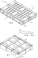
The basic pallet of this container that above-mentioned patent describes is carried on also the retrofit basis of pallet of basic pallet of the present invention when being formed on folded state, Fig. 7 and 8 expressions have several folding containers, as shown in the figure through the pallets of remodeling on it.As described in early stage patent, when these containers are in folded state, with the container intussusception and be interlocked.The end frame of container is mainly used in cover superimposition interlocking.It is in place that Fig. 7 is illustrated in container folding on the pallet.And Fig. 8 represents that container and pallet disassemble.Pallet 50 is different from simple pallet shown in Figure 1, and it has additional pin 51 and 52 on top panel, and perforation 53 is arranged on bottom panel, and the axis of described perforation 53 is aimed at cooresponding pin.(it should be noted that respectively bores a hole 53 comprises the embolus that can push, and it can seal the perforation in the lath 27 of pallet).Obviously,, can learn, be provided with the pin 52 and the perforation 53 of corresponding location and sizing in the relative side of pallet though do not illustrate.Though the Foldable container described in the above-mentioned patent can be used for this pallet, the difference of these containers is to have different thickness.That is, sidewall paneling comprises folding flap 54, and when container was upright, the remainder of flap matching board formed the higher sidewall of size.And the end wall 56 of container can extend as required, so that cooperate with sidewall, thereby increases the height of container, and these ends that have a container endwall framework are mainly played cover superimposition interlocked and used.
As shown in the figure, pin 51 and 52 is mutually spaced apart with suitable distance, so that hold folding container, adopts the end of these pin fixed containers.
Also comprise top frame 60 in this embodiment, make folding container stacking fixing reliably.Fig. 9 represents to be positioned at this top frame and the container at the top of stacking.In many aspects, this framework is identical with the framework that is used for upright vessel.In this case, this top frame comprises pair of L-shaped end plate 61, makes the extruding rod member of this end plate 61, and is identical with the extruding rod member of the L shaped end plate 21 of making pallet top panel part.Except being provided with the described energy drag device of Fig. 3 F, transverse plate 65 is corresponding to the transverse plate or the median plate 18 of pallet top panel part.
Also comprise five transverse slats, a pair of transverse slats 63 and 64 that is positioned at each end, and central transverse slats 65.Fig. 3 G represents the end view of lath 63.As shown in the figure, except that lath was solid rather than lattice structure, lath 63 was substantially the same in the top panel lath 19 partly of basic pallet.(preferably lath 63 has the solid structure, and this is for when being formed with the lath of cut-out 66, prevents to expose the inside opening of lath, will illustrate below.) adopt the rod member very identical with the top panel transverse plate 19 partly of pallet to make lath 64, that is, adopt the extruding lattice rod member shown in Fig. 3 D.Basic demand for these laths is the end frame that guarantees to cover Foldable container, so that by the top frame assembly pressure is applied on the container, and makes applied pressure rectangular distribution on container.
As shown in the figure, be with 67, guarantee that container is secured in place on the pallet in the cut-out 66 of end lath 63, the flexibility that the container of stacking is tied up in arrangement.Finished product member after Figure 10 and 11 expressions are tied up wherein is fixed to a large amount of Foldable containers on the pallet of the present invention by top frame of the present invention.
Wish that in many cases container carries with folding form.Pallet 50 and relative top frame 60 can be provided for this reason.So, require can recycle for Foldable container design-calculated pallet and top frame.The structure of design-calculated pallet and top frame is suitable for being nested in together, and recycles easily.Figure 12,13 expression this pallet and top frame, Figure 12 represents the assembly set of a pallet/top frame, and Figure 13 represents that the assembly set of a plurality of pallet/top frame is stacked in together, so that simply carry and load and unload.Can see that with reference to Figure 12 the cut-out 66 of top frame installed the pin 51 and 52 on the pallet.Therefore, this pin has two different functions at least, and a function is that the Foldable container that keeps lower is positioned at suitable position; Another function is that the assurance container is correctly aimed at top frame.Figure 13 represents that the pallet of a plurality of Foldable containers and top frame assembly are stacked in together.Can see, in the perforation 53 on a pallet, lay the pin 52 of pallet below it.In addition, the flexibility of setting keeps together with 67 assembly sets with stacking.
As mentioned above, the structure of pallet is such, and its most of parts are made by same extruding rod member.Figure 14 is a scheme drawing of making this rod member.Left side is in the drawings represented to produce the extruding rod member by each manufacturing line.As shown in the figure, only there are four line 71-74 to provide the whole rod members that need for the major part of basic pallet.Other three line 76-78 are U.S. Pat-5,450,962 disclosed this can be uprightly and collapsible container pallet and the needed optional feature of top frame are provided.In this case, but the rod member that manufacturing line 76 squeezes out is used for making the guide of the pallet of upright vessel shown in Figure 4.And the rod member that manufacturing line 77 and 78 squeezes out is used for producing the lath of two top frame.
As described in beginning as this circumstantial letter, the applicant limits above preferred embodiment and its remodeling.Claims of the present invention, with and equivalent limit the scope of protection of present invention.
Claims (13)
1. firm and lightweight plastic pallet, it is characterized in that described plastic pallet is by a plurality of component set-ups, these parts can be divided into several groups, and those parts in each group can be made by same plastics rod member, and described plastic pallet comprises following discrete parts:
A) top panel part, it forms the surface of pallet, and this surface is connected with the goods that is transferred, and described tray surface comprises a plurality of transverse plates and a pair of boundary plank, and each described boundary plank seals an end of described transverse plate;
B) bottom panel part, the stayed surface of its contact pallet; With
C) a plurality of interval block extends between described top panel partial sum bottom panel part and fixing, and described top panel partial sum bottom panel is partly separated, and forms passage between described top panel partial sum bottom panel part, picks up bar so that receive the inspection of pallet.
2. according to the described plastic pallet of claim 1, it is characterized in that, described interval block is made by same plastics rod member, the rod member of the described interval block that is crushed to has common hollow interior structure, strengthening web is wherein arranged, so that support the wall of block, therefore described each interval block is exposed to this end by opposed end, described hollow interior and web in the partially enclosed block of described top panel partial sum bottom panel with respect to directed setting of described top panel partial sum bottom panel part.
3. according to the described plastic pallet of claim 2, it is characterized in that, described interval block has the common rectangular cross section with two pairs of mutual opposed outer walls, inside at described rod member is provided with web, in each described interval block, comprise interior transverse wall, transverse wall extends between the mutual opposed outer wall of described rod member in described, also comprise a pair of mutual opposed chevron pointing web, respectively another central authorities to mutual opposed outer wall are connected to the part of the first mutual opposed walls, this wall is supported by described internal transverse wall.
4. according to the described plastic pallet of claim 1, it is characterized in that described transverse plate is made by same plastics rod member, the rod member of described transverse plate is the common hollow body that inside has web, web is as the strut member of outer wall, and each transverse plate of formation has a pair of mutual opposed open end; Described top panel partly comprises a pair of spaced boundary plank, and described boundary plank and transverse plate are adjacent, seals mutual opposed open end by described boundary plank.
5. according to the described plastic pallet of claim 1, it is characterized in that, adopt welding method that described transverse plate is welded on the boundary plank.
6. according to the described plastic pallet of claim 1, it is characterized in that described transverse plate is made by same plastics rod member, described bottom panel partly has frame element, and described frame element is made by the rod member of described transverse plate.
7. according to the described plastic pallet of claim 1, it is characterized in that having two groups of transverse plates, each is organized transverse plate and has different structures, and the plastics rod member of corresponding two kinds of different transverse plates is arranged, and makes transverse plate by described plastics rod member.
8. according to the described plastic pallet of claim 1, it is characterized in that each boundary plank has L shaped section, the profile of its one leg seals the respective end portions of a plurality of transverse plates.
9. according to the described plastic pallet of claim 8, it is characterized in that on the one leg in addition of the described L shaped boundary plank of described each boundary plank, having a plurality of energy drag devices, so that boundary plank is rigidly connected on the described transverse plate.
10. according to the described plastic pallet of claim 1, it is characterized in that the tray surface that described top panel partly is provided with comprises the lath of interlocking, be used for and container interlocking by described pallet carrying.
11. according to the described plastic pallet of claim 10, it is characterized in that having four interlocking laths at described tray surface, described lath is parallel to each other, the edge of a pair of lath and mutual opposed top panel part is adjacent, and another is central adjacent to lath and tray surface.
12. according to the described plastic pallet of claim 1, it is characterized in that,
In described top panel part, described a plurality of transverse plates are made by same bar material, and each transverse plate has a pair of mutual opposed open end; And the L-shaped separately section of described boundary plank, one leg wherein seals the mutual opposed end of described transverse plate, and described boundary plank made by same bar material, and this bar material is inequality with the sort of bar material of making transverse plate;
Have frame element in described bottom panel part, these frame elements are to use the bar material identical with the rod member of the transverse plate of making the top panel part to make; With
Described interval block is also made by same bar material, this bar material is crushed to, has hollow substantially inside, wherein have strengthening web, so that support the wall of block, each at interval block with respect to directed setting of described top panel partial sum bottom panel part, therefore by described top panel partial sum bottom panel partially enclosed the opposed end that described hollow interior and web can be come out on the block.
13. according to the described plastic pallet of claim 12, it is characterized in that, described top panel partly comprises the lath of a plurality of interlockings, described lath and the container interlocking of carrying by described pallet, have four interlocking laths at described tray surface, described lath is parallel to each other, and a pair of lath is with opposed described top panel edge partly is adjacent mutually, and another is central adjacent to lath and tray surface.
Applications Claiming Priority (2)
| Application Number | Priority Date | Filing Date | Title |
|---|---|---|---|
| US08/631,633 | 1996-04-08 | ||
| US08/631,633 US5836255A (en) | 1996-04-08 | 1996-04-08 | Pallet for erected and collapsible container/pallet system |
Publications (2)
| Publication Number | Publication Date |
|---|---|
| CN1215373A CN1215373A (en) | 1999-04-28 |
| CN1075018C true CN1075018C (en) | 2001-11-21 |
Family
ID=24532060
Family Applications (1)
| Application Number | Title | Priority Date | Filing Date |
|---|---|---|---|
| CN97193549A Expired - Fee Related CN1075018C (en) | 1996-04-08 | 1997-01-16 | Pallet for collapsible container/pallet system |
Country Status (8)
| Country | Link |
|---|---|
| US (1) | US5836255A (en) |
| EP (1) | EP0801001B1 (en) |
| CN (1) | CN1075018C (en) |
| AT (1) | ATE192716T1 (en) |
| CA (1) | CA2186194C (en) |
| DE (1) | DE69701917T2 (en) |
| IL (1) | IL126327A (en) |
| WO (1) | WO1997037896A1 (en) |
Families Citing this family (44)
| Publication number | Priority date | Publication date | Assignee | Title |
|---|---|---|---|---|
| US5865315A (en) * | 1997-01-06 | 1999-02-02 | Uitz; Mark O | Material transport system |
| US6250234B1 (en) * | 1998-07-01 | 2001-06-26 | Rehrig Pacific Company | Method of reinforcing a plastic pallet |
| US6216608B1 (en) * | 1998-07-01 | 2001-04-17 | The Geon Company | Plastic pallet |
| US6283044B1 (en) | 1998-07-01 | 2001-09-04 | Rehrig Pacific Company | Pallet assembly |
| US6294114B1 (en) | 1998-08-20 | 2001-09-25 | Scott A. W. Muirhead | Triple sheet thermoforming apparatus, methods and articles |
| US6749418B2 (en) | 1998-08-20 | 2004-06-15 | Scott A. W. Muirhead | Triple sheet thermoforming apparatus |
| USD443969S1 (en) | 1999-10-22 | 2001-06-19 | Rehrig Pacific Company | Pallet |
| US7342496B2 (en) | 2000-01-24 | 2008-03-11 | Nextreme Llc | RF-enabled pallet |
| US6661339B2 (en) | 2000-01-24 | 2003-12-09 | Nextreme, L.L.C. | High performance fuel tank |
| US6943678B2 (en) | 2000-01-24 | 2005-09-13 | Nextreme, L.L.C. | Thermoformed apparatus having a communications device |
| US8077040B2 (en) | 2000-01-24 | 2011-12-13 | Nextreme, Llc | RF-enabled pallet |
| ES2172403B1 (en) * | 2000-06-07 | 2003-12-16 | Plaspalet S A | PREMOLDED MODULES FOR THE CONFECTION OF PALLETS AND PALLETS OBTAINED. |
| FR2810638B1 (en) * | 2000-06-22 | 2002-12-06 | Solvay | PALLET IN PLASTIC MATERIAL |
| AU2001286752A1 (en) | 2000-08-24 | 2002-03-04 | Infiltrator Systems, Inc. | Plastic pallet design |
| US7165499B2 (en) * | 2003-02-04 | 2007-01-23 | Rehrig Pacific Company | Reinforced pallet |
| US20060048687A1 (en) * | 2004-09-07 | 2006-03-09 | Trienda, A Wilbert Company | Reduced profile, improved-strength, improved-ridgity, plastic one-way pallet |
| US20060081158A1 (en) * | 2004-10-19 | 2006-04-20 | Fitzpatrick Technologies, L.L.C. | Pultrusion pallet |
| WO2006089302A2 (en) * | 2005-02-18 | 2006-08-24 | The Engineered Pallet Company, Llc | Plastic pallet having diagonally corrugated deck |
| US20060201400A1 (en) * | 2005-02-18 | 2006-09-14 | Moore Roy E Jr | Plastic pallet having deck suspension system |
| US20060201402A1 (en) * | 2005-03-01 | 2006-09-14 | Moore Roy E Jr | Thermoplastic pallet for transporting food goods |
| US8235217B2 (en) * | 2005-05-24 | 2012-08-07 | Stolzman Michael D | Bulk container with cap and pallet base |
| US20070017422A1 (en) * | 2005-07-19 | 2007-01-25 | Fitzpatrick Technologies, Llc | Pallet with composite components |
| US20070017423A1 (en) * | 2005-07-19 | 2007-01-25 | Ingham Terry L | Pallet With Recycled Components |
| US20080190922A1 (en) * | 2007-02-08 | 2008-08-14 | Kraeling Brett B | Collapsible shipping container |
| JP2008290801A (en) * | 2007-05-22 | 2008-12-04 | Zeon Logistical Materials Co Ltd | Pile board for printing press |
| US7690315B2 (en) | 2007-06-15 | 2010-04-06 | Rehrig Pacific Company | Nestable pallet |
| US8261673B2 (en) * | 2007-09-26 | 2012-09-11 | Fitzpatrick Technologies | Pallet with lead board |
| GB2449374B (en) * | 2008-07-23 | 2009-05-13 | Rftraq Ltd | A pallet made of plastics material |
| CH704180A2 (en) * | 2010-12-01 | 2012-06-15 | Konsortium Two In One | Modular range. |
| CA2824262A1 (en) * | 2011-01-20 | 2012-07-26 | Bede WHITEFORD | Pallet leader board system |
| CN102152477A (en) * | 2011-05-24 | 2011-08-17 | 常熟市汽车饰件有限公司 | Friction welding method for automobile coatrack |
| US8978912B1 (en) | 2012-03-19 | 2015-03-17 | Response Holdings Corporation | Collapsible shipping tote |
| US8943981B2 (en) * | 2013-03-14 | 2015-02-03 | Daniel Kelly | Reinforced plastic pallet |
| CN104129549A (en) * | 2014-07-11 | 2014-11-05 | 芜湖富春染织有限公司 | High-load-bearing cheese supporting plate |
| WO2016040300A1 (en) | 2014-09-08 | 2016-03-17 | Green Ox Pallet Technology, Llc | Lightweight and rigid pallet |
| US9511897B2 (en) * | 2014-09-15 | 2016-12-06 | Air-Bag Packing Co., Ltd. | Assemblable pallet |
| US9511898B2 (en) * | 2014-09-15 | 2016-12-06 | Air-Bag Packing Co., Ltd. | Assemblable pallet |
| US9352874B2 (en) * | 2014-09-25 | 2016-05-31 | Lenovo Enterprise Solutions (Singapore) Pte. Ltd. | Low profile, light weight hybrid wood/paper pallet |
| TWI599516B (en) * | 2014-11-19 | 2017-09-21 | Air-Bag Packing Co Ltd | Adjustable size of the modular pallet |
| CN105292678B (en) * | 2014-12-09 | 2017-10-17 | 昆山亚比斯环保包装材料有限公司 | A kind of pallet |
| CN105083699A (en) * | 2015-09-02 | 2015-11-25 | 青岛赛尔板业有限公司 | Composite material pultrusion tray |
| EP3630633A1 (en) * | 2017-05-26 | 2020-04-08 | Integrated Composite Products, Inc. | Composite pallet |
| US10562666B2 (en) | 2018-05-31 | 2020-02-18 | Chep Technology Pty Limited | Repairable plastic pallet with grommets in the top deck and associated methods |
| WO2020056896A1 (en) * | 2018-09-20 | 2020-03-26 | 重庆惠科金渝光电科技有限公司 | Pallet and packaging structure |
Citations (2)
| Publication number | Priority date | Publication date | Assignee | Title |
|---|---|---|---|---|
| US4597339A (en) * | 1982-04-14 | 1986-07-01 | Mccaffrey Hugh | Pallet |
| US5388533A (en) * | 1988-08-09 | 1995-02-14 | Pigott; Brandon L. | Pallet and components thereof |
Family Cites Families (40)
| Publication number | Priority date | Publication date | Assignee | Title |
|---|---|---|---|---|
| DE401658C (en) * | 1924-09-09 | Carl August Bembe | Big boom for sailing boats | |
| US3126843A (en) * | 1964-03-31 | de laney | ||
| US2990058A (en) * | 1959-03-17 | 1961-06-27 | Saint Gobain Corp | Unitized shipment package |
| DE1814591A1 (en) * | 1967-12-15 | 1969-12-11 | Cegedur Gp | Load bearing plate |
| GB1005589A (en) * | 1962-05-04 | 1965-09-22 | Karl Dahmen | Supporting-foot for goods to be transported |
| FR1322667A (en) * | 1962-05-21 | 1963-03-29 | Support foot for parcel shipping | |
| US3315800A (en) * | 1964-12-14 | 1967-04-25 | Hampton R Wagner | Collapsible plywood shipping device |
| US3540385A (en) * | 1968-07-18 | 1970-11-17 | Mojonnier Bros Co | Materials handling pallet |
| US3557512A (en) * | 1968-07-22 | 1971-01-26 | Dow Chemical Co | Structural unit with x-shaped inserts |
| US3678868A (en) * | 1969-04-03 | 1972-07-25 | Kyowa Electric | Pallet |
| US3610173A (en) * | 1969-04-04 | 1971-10-05 | John W Mcilwraith | Plastic pallet |
| US3664271A (en) * | 1969-12-15 | 1972-05-23 | Ernest Harold Wolder | Plastic molded pallet |
| US3720176A (en) * | 1970-08-13 | 1973-03-13 | Moraine Box Co | Molded pallet |
| AT321809B (en) * | 1971-06-04 | 1975-04-25 | Freya Plastic Delbrouck F | Stackable fruit or vegetable crates |
| US3814280A (en) * | 1972-01-17 | 1974-06-04 | Metalcraft Bristol Ltd | Metal box structure and components therefor |
| US3814031A (en) * | 1972-05-26 | 1974-06-04 | Monsanto Co | Plastic pallets |
| DE2365344A1 (en) * | 1973-03-09 | 1974-09-12 | Freya Plastic Delbrouck F | SKID TRAINING OF A PLASTIC PALLET |
| GB1459433A (en) * | 1973-03-30 | 1976-12-22 | Powerscreen Int Ltd | Remote control system |
| US3878796A (en) * | 1973-12-05 | 1975-04-22 | Econopal Inc | Plastic pallet assembly |
| JPS5239532B2 (en) * | 1974-01-24 | 1977-10-05 | ||
| FR2291101A1 (en) * | 1974-11-14 | 1976-06-11 | Cavel Michel De | Material handling open frame pallet - is converted into container for truck by addition of pre-fitted components |
| US3954067A (en) * | 1974-11-22 | 1976-05-04 | Miles Ray P | Reversible pallet |
| US3989140A (en) * | 1975-03-03 | 1976-11-02 | A & E Plastik Pak Co., Inc. | Apparatus for unitizing stacked product containers for shipment |
| DE2516108C3 (en) * | 1975-04-12 | 1979-11-22 | Fritz 4300 Essen Klawitter | Transport pallet |
| GB1571190A (en) * | 1975-12-09 | 1980-07-09 | Wavin Bv | Pallets |
| US4301730A (en) * | 1977-09-29 | 1981-11-24 | Pamarco Incorporated | Anilox roll and method of making the same |
| DE3011139A1 (en) * | 1980-03-22 | 1981-10-01 | Erich Ing.(grad.) 8776 Heigenbrücken Amrogowicz | Pallet system for foodstuffs industry - includes flat pallet with superimposed container or shelves and fitted with base pallet used as contamination barrier |
| FR2559126B1 (en) * | 1984-02-03 | 1986-12-26 | Sifar Sa | PALLET TROLLEY FOR THE STORAGE AND TRANSPORT OF GROUPING TRAYS CONTAINING PACKAGING |
| US4597338A (en) * | 1984-11-14 | 1986-07-01 | Pinckney Molded Plastics, Inc. | Pallet |
| FR2590870B1 (en) * | 1985-12-04 | 1988-06-24 | Allibert Sa | REINFORCED LOADING PALLET AND METHOD FOR REINFORCING SUCH A PALLET |
| US4720115A (en) * | 1986-05-02 | 1988-01-19 | Houston Rehrig | Plastic dolly |
| US4843976A (en) * | 1988-08-09 | 1989-07-04 | Pigott Maurice J | Plastic pallet |
| US5197395A (en) * | 1988-08-09 | 1993-03-30 | Pigott Maurice J | Plastic pallet with deck assembly |
| IT219385Z2 (en) * | 1990-03-08 | 1993-02-26 | PALLET WITH ELEMENTS IN PLASTIC MATERIAL | |
| DE4016589A1 (en) * | 1990-05-23 | 1991-11-28 | Thyssen Polymer Gmbh | Multipart hygienic pallet for transporting foods - has plastics skids and plastics transverse stays with moulded fasteners |
| FR2697502A1 (en) * | 1992-11-03 | 1994-05-06 | Chanal Hugon Raymond | Extruded pallet of synthetic material - has extruded hollow lower and upper boards and posts assembled face-to-face by ultrasonic welding |
| US5458069A (en) * | 1993-02-05 | 1995-10-17 | Stolzman; Michael D. | Plastic skid and method of manufacture |
| EP0690809B1 (en) * | 1993-04-01 | 1997-02-12 | World Wide Pallets Limited | A load-handling pallet |
| US5450962A (en) * | 1993-09-23 | 1995-09-19 | Uitz; Mark O. | Reusable container |
| US5497708A (en) * | 1994-09-30 | 1996-03-12 | Chrysler Corporation | Pallet with adjustable article mounting hardware and article attachment method |
-
1996
- 1996-04-08 US US08/631,633 patent/US5836255A/en not_active Expired - Lifetime
- 1996-09-23 CA CA002186194A patent/CA2186194C/en not_active Expired - Fee Related
-
1997
- 1997-01-16 CN CN97193549A patent/CN1075018C/en not_active Expired - Fee Related
- 1997-01-16 IL IL12632797A patent/IL126327A/en not_active IP Right Cessation
- 1997-01-16 WO PCT/US1997/000451 patent/WO1997037896A1/en active Search and Examination
- 1997-02-27 EP EP97103223A patent/EP0801001B1/en not_active Expired - Lifetime
- 1997-02-27 DE DE69701917T patent/DE69701917T2/en not_active Expired - Fee Related
- 1997-02-27 AT AT97103223T patent/ATE192716T1/en not_active IP Right Cessation
Patent Citations (2)
| Publication number | Priority date | Publication date | Assignee | Title |
|---|---|---|---|---|
| US4597339A (en) * | 1982-04-14 | 1986-07-01 | Mccaffrey Hugh | Pallet |
| US5388533A (en) * | 1988-08-09 | 1995-02-14 | Pigott; Brandon L. | Pallet and components thereof |
Also Published As
| Publication number | Publication date |
|---|---|
| IL126327A0 (en) | 1999-05-09 |
| DE69701917T2 (en) | 2001-01-11 |
| AU726644B2 (en) | 2000-11-16 |
| CN1215373A (en) | 1999-04-28 |
| WO1997037896A1 (en) | 1997-10-16 |
| DE69701917D1 (en) | 2000-06-15 |
| CA2186194C (en) | 2000-11-28 |
| AU1533797A (en) | 1997-10-29 |
| EP0801001A1 (en) | 1997-10-15 |
| US5836255A (en) | 1998-11-17 |
| IL126327A (en) | 2001-07-24 |
| CA2186194A1 (en) | 1997-10-09 |
| ATE192716T1 (en) | 2000-05-15 |
| EP0801001B1 (en) | 2000-05-10 |
Similar Documents
| Publication | Publication Date | Title |
|---|---|---|
| CN1075018C (en) | Pallet for collapsible container/pallet system | |
| US5950546A (en) | Double deck fold-up pallet | |
| SK57194A3 (en) | Corrugated pallet | |
| CN101312888B (en) | A pallet | |
| US5184558A (en) | Pallet and method and apparatus for making same | |
| CN1039892C (en) | Integrated two-way paper cargo pallet | |
| US5941177A (en) | Recyclable, heavy duty, lightweight, moisture resistant corrugated fiberboard pallet | |
| KR100263314B1 (en) | Pallet | |
| CN1011037B (en) | Package assembly | |
| CN1842471A (en) | Bulk shipping box assembly with detachable pallet | |
| CN1211956A (en) | Material transport system | |
| CN1946610A (en) | Corrugated cardboard supports | |
| CN106715281A (en) | Platforms made of paper materials | |
| CN1649776A (en) | Corrugated cardboard pallets and improvements in and relating to corrugated cardboard pallets | |
| EP1281632B1 (en) | Cushioning material for packaging and method and device for manufacturing the cushioning material | |
| NL9600004A (en) | Stackable packaging with reinforced corners - has at sides of corner reinforcing members oversize to snap fit | |
| US4872574A (en) | Container | |
| CN108502384A (en) | A kind of commuting case and packing method detachably transported | |
| US20030052038A1 (en) | Corrugated container with integral pallet | |
| US4614277A (en) | Pallet with tensioned strips and bulk bin | |
| CN2780640Y (en) | Location frame structure of corruagted paper trestle plate top | |
| CN1043519C (en) | Corrugated pallet | |
| JP7293924B2 (en) | Welded can manufacturing method and apparatus | |
| WO2023100204A1 (en) | Pallet for supporting and transporting goods | |
| ITMI980940A1 (en) | CONTAINER ON SHOVEL |
Legal Events
| Date | Code | Title | Description |
|---|---|---|---|
| C06 | Publication | ||
| PB01 | Publication | ||
| C10 | Entry into substantive examination | ||
| SE01 | Entry into force of request for substantive examination | ||
| C14 | Grant of patent or utility model | ||
| GR01 | Patent grant | ||
| C19 | Lapse of patent right due to non-payment of the annual fee | ||
| CF01 | Termination of patent right due to non-payment of annual fee |