CN107454355B - Sliding structure of rear decorative cover plate of liquid crystal television - Google Patents
Sliding structure of rear decorative cover plate of liquid crystal television Download PDFInfo
- Publication number
- CN107454355B CN107454355B CN201710899193.2A CN201710899193A CN107454355B CN 107454355 B CN107454355 B CN 107454355B CN 201710899193 A CN201710899193 A CN 201710899193A CN 107454355 B CN107454355 B CN 107454355B
- Authority
- CN
- China
- Prior art keywords
- cover plate
- decorative cover
- rear decorative
- liquid crystal
- sliding
- Prior art date
- Legal status (The legal status is an assumption and is not a legal conclusion. Google has not performed a legal analysis and makes no representation as to the accuracy of the status listed.)
- Expired - Fee Related
Links
Images


Classifications
-
- H—ELECTRICITY
- H04—ELECTRIC COMMUNICATION TECHNIQUE
- H04N—PICTORIAL COMMUNICATION, e.g. TELEVISION
- H04N5/00—Details of television systems
- H04N5/64—Constructional details of receivers, e.g. cabinets or dust covers
Landscapes
- Engineering & Computer Science (AREA)
- Multimedia (AREA)
- Signal Processing (AREA)
- Devices For Indicating Variable Information By Combining Individual Elements (AREA)
Abstract
The invention discloses a sliding structure of a rear decorative cover plate of a liquid crystal television, which is arranged on the liquid crystal television with a sound box base and positioned between a small rear shell and the rear decorative cover plate; the rear decorative cover plate is arranged on the back surface of the small rear shell; wherein: under the condition of wall-hung installation, the rear decorative cover plate slides downwards by the thickness of the sound box base to expose the rack screw through hole on the small rear shell; because the rear decorative cover plate adopts a structure capable of sliding downwards, when the loudspeaker box is mounted on a wall, the upright post structure and the screw holes which are used for mounting the loudspeaker box base on the small rear shell are shielded, so that the integral aesthetic feeling that the screw holes do not exist behind the large-size liquid crystal television when the loudspeaker box is erected is considered, and the integral aesthetic feeling that the screw holes do not exist behind the large-size liquid crystal television when the loudspeaker box is mounted on the wall is also considered.
Description
Technical Field
The invention relates to the field of large-size liquid crystal televisions with sound box bases, in particular to a sliding structure of a rear decorative cover plate of a liquid crystal television.
Background
With the popularization and development of large-size liquid crystal televisions (i.e., liquid crystal televisions above 55 inches), consumers can not only pay attention to the integral aesthetic feeling brought to the front of the large-size liquid crystal television by the front decorative panel (or strip), but also pay attention to the integral aesthetic feeling brought to the back of the large-size liquid crystal television by the back decorative cover plate which is invisible or less concerned, and especially, the feeling can be taken into consideration of the installation conditions of standing up the television and hanging on the wall.
The rear shell of a large-size liquid crystal television in the prior art is fixed through screws, under the normal condition, a rear decorative cover plate is installed on a small rear shell (the length and the width of the rear decorative cover plate are much smaller than those of a liquid crystal screen), under the condition of vertical machine installation, any hole groove or rib column structure is not required to be arranged on the rear decorative cover plate, if wall hanging installation is considered, the two conditions can be divided into two conditions, one is that the rear decorative cover plate cannot be detached, the hole groove or rib column required by the wall hanging installation is required to be added on the non-detachable rear decorative cover plate for wall hanging installation, and the other is that the rear decorative cover plate can be detached, and the rear decorative cover plate is detached and can be used for wall hanging installation.
However, in the former case, the rear decorative cover plate with the holes or ribs seriously affects the overall aesthetic feeling behind the large-sized liquid crystal television; in the latter case, not only is the detached rear decorative cover left unused and occupying space, but the small rear housing exposed after detachment still destroys the overall aesthetic appeal behind the large-sized liquid crystal television.
Therefore, there is still a need for improvement and development of the prior art.
Disclosure of Invention
In order to solve the technical problem, the invention provides a sliding structure of a rear decorative cover plate of a liquid crystal television, which can give consideration to the integral aesthetic feeling of the rear of a large-size liquid crystal television under two installation conditions of erecting the television and hanging on a wall.
The technical scheme of the invention is as follows: a sliding structure of a rear decorative cover plate of a liquid crystal television is arranged on the liquid crystal television with a sound box base and is positioned between a small rear shell and the rear decorative cover plate; the rear decorative cover plate is arranged on the back surface of the small rear shell; wherein: and under the condition of wall-hung installation, the rear decorative cover plate slides downwards by the thickness of the sound box base, and is used for exposing the rack screw through hole on the small rear shell.
The sliding structure of the rear decorative cover plate of the liquid crystal television is characterized in that: a plurality of sliding column hooks are arranged on one surface, facing the small rear shell, of the rear decorative cover plate; each sliding column hook consists of a sliding column and a hook plate, the sliding column is vertically connected to the surface of the decorative cover plate, and the hook plate is eccentrically connected to the top of the sliding column and used for hooking the small rear shell; correspondingly, a plurality of first slide rail grooves are arranged on the small rear shell and correspond to the slide column hooks on the rear decorative cover plate; the lower end of the first slide rail groove is provided with a dismounting hole which is matched with the hook plate of the corresponding slide post hook to penetrate through so as to be convenient for dismounting the rear decorative cover plate; elastic limiting salient points are symmetrically arranged at the upper end of the first slide rail groove and used for clamping a slide column of a corresponding slide column hook when the vertical machine is installed so as to position the upper limit position of the rear decorative cover plate; first guide ribs extend from two sides of the first slide rail groove to the thickness direction of the small rear shell respectively, the distance from the top surface of each first guide rib to the outer side surface of the small rear shell is smaller than or equal to the distance from the bottom surface of the hook plate of the sliding column hook to the inner side surface of the rear decorative cover plate, and the top surface of one end, close to the dismounting hole, of each first guide rib is an inclined surface.
The sliding structure of the rear decorative cover plate of the liquid crystal television is characterized in that: a plurality of iron sheet grooves are formed in one surface, facing the small rear shell, of the rear decorative cover plate; an iron sheet which can be magnetically attracted is arranged in each iron sheet groove; correspondingly, a plurality of magnet seats with elastic clamping grooves are arranged on the small rear shell and correspond to the iron sheet grooves on the rear decorative cover plate, and a magnet is clamped in each magnet seat and used for adsorbing the iron sheets in the corresponding iron sheet grooves when the rear decorative cover plate slides up and down.
The sliding structure of the rear decorative cover plate of the liquid crystal television is characterized in that: and two groups of button limiting assemblies are transversely installed on one surface of the lower part of the small rear shell facing the screen body structural member at intervals, and are used for positioning the rear decorative cover plate after sliding downwards on the back surface of the small rear shell and preventing the rear decorative cover plate from being separated from the small rear shell.
The sliding structure of the rear decorative cover plate of the liquid crystal television is characterized in that: two second slide rail grooves are transversely arranged at intervals at the bottom of the small rear shell, a button hole matched with the button limiting assembly is formed in the bottom end of each second slide rail groove, positioning ribs and screw bottom hole columns are symmetrically arranged on two sides of the button hole, and positioning clamping grooves are formed in the upper portions of the positioning ribs; and second guide ribs respectively extend from two sides of the second slide rail groove to the thickness direction of the small rear shell, and the distance from the top surface of each second guide rib to the outer side surface of the small rear shell is less than or equal to the distance from the bottom surface of the hook plate of the sliding column hook to the inner side surface of the rear decorative cover plate.
The sliding structure of the rear decorative cover plate of the liquid crystal television is characterized in that: each group of button limiting assemblies consists of a fixed seat, a spring, a sliding sheet and a button; after the sliding piece is assembled on the small rear shell, the sliding piece is positioned at the bottom of the button, and the spring is positioned between the inner bottom surface of the fixed seat and the bottom surface of the sliding piece; screw through-hole columns are symmetrically arranged at two ends of the fixed seat; two ends of the sliding sheet are symmetrically provided with clamping teeth which are used for being clamped into the positioning clamping grooves in an adaptive mode; the head of the button is provided with a positioning groove for supporting a sliding column of a corresponding sliding column hook when the button is mounted on a wall so as to position the lower limit position of the rear decorative cover plate; the top surface of the button is provided with a counter bore with a straight rib for manually pressing and rotating the button.
The sliding structure of the rear decorative cover plate of the liquid crystal television is characterized in that: the upper edge of the screen body structural member is provided with a wall hanging riveting column which is used for connecting and fixing a wall hanging rack on the back of the small back shell through a rack screw during wall hanging installation; correspondingly, the rack screw through hole is formed in the upper edge of the small rear shell.
According to the sliding structure of the rear decorative cover plate of the liquid crystal television, which is provided by the invention, as the rear decorative cover plate adopts a structure capable of sliding downwards, when the rear decorative cover plate is hung on a wall, a stand column structure and screw holes for mounting a sound box base on a small rear shell are shielded, so that the integral aesthetic feeling that no screw hole exists behind a large-size liquid crystal television when the rear decorative cover plate is hung on the wall is considered, and the integral aesthetic feeling that no screw hole exists behind the large-size liquid crystal television when the rear decorative cover plate is hung on the wall is also considered.
Drawings
FIG. 1 is a state diagram of the sliding structure of the rear decorative cover plate of the LCD TV set in the vertical state;
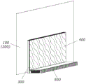
FIG. 2 is a view showing a state of the sliding structure of the rear decorative cover plate of the LCD TV according to the embodiment of the present invention when hanging on a wall;
FIG. 3 is a rear view of the sliding structure of the rear decorative cover plate of the LCD TV according to the embodiment of the present invention after the vertically installed speaker base is removed;
fig. 4 is an exploded view of main parts of an embodiment of a sliding structure of a rear decorative cover plate of a liquid crystal television according to the present invention;
fig. 5 is a structural view of a rear decorative cover plate used in the sliding structural embodiment of the rear decorative cover plate of the liquid crystal television set of the present invention;
FIG. 6 is a structural view of a small rear case used in an embodiment of a sliding structure of a rear decorative cover plate of a liquid crystal television set according to the present invention;
fig. 7 is an enlarged view of a single set of button limiting components mounted on a small rear shell according to an embodiment of the sliding structure of the rear decorative cover plate of the liquid crystal television.
Detailed Description
The embodiments and examples of the present invention will be described in detail below with reference to the accompanying drawings, and the described embodiments are only for the purpose of illustrating the present invention and are not intended to limit the embodiments of the present invention.
As shown in fig. 1, fig. 1 is a state diagram of a sliding structure of a rear decorative cover plate of a liquid crystal television according to an embodiment of the present invention when the liquid crystal television is set up, where the liquid crystal television according to the present invention refers to a large-sized liquid crystal television with a sound box base (or a base with a certain thickness such as a main box base) and more than 55 inches, and includes a liquid crystal screen 100 and a screen structure 200 thereof, a small rear shell 300, a rear decorative cover plate 400, and a sound box base 500; the small rear case 300 is mounted on the panel structure 200 of the liquid crystal display 100, the rear decorative cover 400 is mounted on the back of the small rear case 300, and the speaker base 500 is connected to the lower edge of the back of the small rear case 300 and is used as a support for the whole large-sized liquid crystal display during the installation of the stereoscopic display.
Referring to fig. 2, fig. 2 is a state diagram of a sliding structure of a rear decorative cover plate of a liquid crystal television according to an embodiment of the present invention when the liquid crystal television is hung on a wall, the sliding structure of the rear decorative cover plate of the liquid crystal television is disposed on the liquid crystal television with a sound box base 500 and is located between the small rear shell 300 and the rear decorative cover plate 400, and in a case of wall-mounted installation, the rear decorative cover plate 400 slides downwards by a distance of the thickness of the sound box base 500 to expose a rack screw through hole on the upper portion of the small rear shell 300 for installing the lower half of the wall-mounted rack 600; meanwhile, the sound box base 500 is reversely buckled on the back surface of the liquid crystal screen 100 above the small rear case 300, and the upper half part of the wall hanging rack 600 is connected with the sound box base 500.
Referring to fig. 3, fig. 3 is a rear view of an embodiment of a sliding structure of a rear decorative cover plate of a liquid crystal television according to the present invention after a speaker base is removed from a vertical installation, before a vertical installation is switched to a wall-mounted installation, the speaker base 500 in fig. 1, which serves as a support member during the vertical installation, needs to be removed, and after the speaker base 500 is removed, since there is no shielding of the speaker base 500, many structures at the lower portion of the back surface of the small rear case 300, particularly four upright post fixing structures 330 for connecting and fixing the speaker base 500, are exposed, which seriously affects the overall aesthetic feeling of the back surface of a large-sized liquid crystal television.
In order to shield the structures located at the lower part of the back surface of the small rear shell 300, the liquid crystal television improves the rear decorative cover plate, adopts a structure capable of sliding downwards for a distance of the thickness of the sound box base 500, and combines a bump limiting structure and a button limiting structure, wherein the bump limiting structure is used for positioning the upper limit position of the decorative cover plate 400, the button limiting structure is used for positioning the lower limit position of the rear decorative cover plate 400, and the magnet attracting structure is used for improving the sliding hand feeling of the rear decorative cover plate 400.
Referring to fig. 4, fig. 4 is an exploded view of main parts of an embodiment of a sliding structure of a rear decorative cover plate of an lcd tv according to the present invention, in a specific embodiment of the sliding structure of the rear decorative cover plate of the lcd tv according to the present invention, a wall-hanging rivet 106 is disposed at an upper edge of the panel structure 200 for connecting and fixing the wall-hanging rack 600 of fig. 2 to the back surface of the small rear housing 300 by a rack screw during wall-hanging installation; correspondingly, the rack screw through hole 306 is also formed in the upper edge of the small rear shell 300; meanwhile, two sets of button position-limiting assemblies 230 are laterally installed at intervals on a surface of the lower portion of the small rear case 300 facing the panel structure 200, for positioning the rear decorative cover plate 400 after sliding downward on the back surface of the small rear case 300, and preventing the rear decorative cover plate 400 from coming off the small rear case 300.
Specifically, referring to fig. 5, fig. 5 is a structural view of a rear decorative cover plate used in an embodiment of a sliding structure of the rear decorative cover plate of a liquid crystal television according to the present invention, fig. 5 shows a structure on an inner side surface of the rear decorative cover plate 400 facing the small rear case 300, and a partial structure at a corner a is enlarged, and a plurality of stud hooks 410 and a plurality of iron piece grooves 420 are provided on a surface of the rear decorative cover plate 400 facing the small rear case 300; each of the strut hooks 410 is composed of a strut 411 and a hook plate 412, the strut 411 is vertically connected to the surface of the trim cover 400, and the hook plate 412 is eccentrically connected to the top of the strut 411 for hooking the small rear case 300; each iron sheet groove 420 is provided with an iron sheet 421 capable of being magnetically attracted.
Correspondingly, referring to fig. 6, fig. 6 is a structural diagram of a small rear housing used in an embodiment of a sliding structure of a rear decorative cover plate of a liquid crystal television according to the present invention, fig. 6 not only shows a structure of the small rear housing 300 facing an inner side surface of a panel structure 200, but also shows a partial structure at a corner B in an enlarged manner (compared with a large figure, a partial B view slightly changes a view angle), and a plurality of first slide rail grooves 310 are provided on the small rear housing 300 to correspond to slide post hooks on the rear decorative cover plate 400; the lower end of the first slide rail groove 310 is provided with a dismounting hole 312 for allowing the hook plate 412 of the corresponding slide post hook 410 in fig. 5 to pass through, so as to facilitate dismounting the rear decorative cover plate 400; elastic limit salient points 311 are symmetrically arranged at the upper end of the first slide rail groove 310 and used for clamping a slide column 411 of a corresponding slide column hook 410 in the drawing 5 when the vertical machine is installed so as to position the upper limit position of the rear decorative cover plate 400; first guide ribs 313 extend from two sides of the first slide rail groove 310 in the thickness direction of the small rear shell 300, the distance from the top surface of the first guide ribs 313 to the outer side surface of the small rear shell 300 (i.e., the surface facing the rear decorative cover plate 400) is less than or equal to the distance from the bottom surface of the hook plate 412 of the strut hook 410 in fig. 5 to the inner side surface of the rear decorative cover plate 400 (i.e., the surface facing the small rear shell 300), and the top surface of the first guide ribs 313 close to the end of the dismounting hole 312 is an inclined surface, so that the first guide ribs can be loosened and tightened when the rear decorative cover plate 400 is mounted and slid upwards.
Specifically, a plurality of magnet seats 314 with elastic clamping grooves are further disposed on the small rear shell 300 and correspond to the iron sheet grooves on the rear decorative cover plate 400, and each magnet seat 314 is provided with a magnet 315 in a clamping manner, so as to adsorb the iron sheet 421 in the corresponding iron sheet groove 420 in fig. 5 when the rear decorative cover plate 400 slides up and down, so as to improve the sliding hand feeling of the rear decorative cover plate 400.
Specifically, referring to fig. 7, fig. 7 is an enlarged view of a single set of button-limiting members mounted on a small rear housing according to an embodiment of the sliding structure of the rear decorative cover plate of the lcd tv of the present invention, (a) is a partially enlarged view of the inner side surface of the small rear housing 300 located at the post-fixing structure 330, (b) is an exploded enlarged view of the single set of button-limiting members 230, and (c) is a partially enlarged view of (a) after assembly (slightly angled compared to (a), but the angle is the same as that of fig. 6).
As shown in (a), two second slide rail grooves 320 are transversely spaced at the bottom of the small rear shell 300, a button hole 321 adapted to mount the button limiting assembly 230 is formed at the bottom end of each second slide rail groove 320, positioning ribs 322 and screw bottom hole columns 323 are symmetrically arranged on two sides of the button hole 321, and positioning clamping grooves 324 are formed in the upper portions of the positioning ribs 322; like the first slide rail groove 310, second guide ribs 325 extend from both sides of the second slide rail groove 320 in the thickness direction of the small rear housing 300, and the distance from the top surface of the second guide ribs 325 to the outer side surface of the small rear housing 300 (i.e., the surface facing the rear trim cover 400) is not more than the distance from the bottom surface of the hook plate 412 of the strut hook 410 to the inner side surface of the rear trim cover 400 (i.e., the surface facing the small rear housing 300) in fig. 5.
As shown in (b), each set of button-limiting members 230 is composed of a fixing base 231, a spring 232, a sliding piece 233 and a button 234; after assembling it to the small rear case 300, the slide 233 is located at the bottom of the button 234, and the spring 232 is located between the inner bottom surface of the holder 231 and the bottom surface of the slide 233; two ends of the fixed seat 231 are symmetrically provided with screw through-hole columns 231 a; two ends of the slide sheet 233 are symmetrically provided with a latch 233a for being fittingly latched into the positioning latch slot 324 in (b); the head of the button 234 is provided with a positioning groove 234a for supporting the sliding column 411 of the sliding column hook 410 corresponding thereto in fig. 5 during wall-hung installation to position the lower limit position of the rear decorative cover plate 400; the top surface of the button 234 is provided with a counter bore with a straight rib 234b for rotating the button 234 by manual depression.
As shown in (c), after the button position limiting assembly 230 is assembled on the small rear case 300 by passing screws through the screw through holes 231a at both ends of the fixing seat 231, in the machine-erected state, the rear decorative cover plate 400 is at the upper limit position under the clamp of the elastic position limiting salient point 311 in fig. 6; when the installation needs to be switched to the wall-hung installation, the sound box base 500 is firstly detached, and then the rear decorative cover plate 400 is forcibly slid downwards until the slide column 411 of the slide column hook 410 in fig. 5 is pressed against the corresponding positioning groove 234a, the clamping teeth 233a symmetrically arranged at the two ends of the slide sheet 233 are clamped in the positioning clamping grooves 324 at the upper parts of the positioning ribs 322 in fig. 7 (a), so that the lower limit position of the rear decorative cover plate 400 can be automatically calibrated; next, as shown in fig. 2, the wall-hanging rack 600 is taken out and fixed at the bottom edge of the detached sound box base 500, and is connected to the wall-hanging rivet 106 of the screen structure 200 through the rack screw through hole 306 of the small back shell 300 in fig. 4 by a wall-hanging screw, so as to connect and fix the sound box base 500 to the upper portion of the small back shell 300.
When the rear decorative cover plate 400 needs to be removed, the rear decorative cover plate 400 can be firstly slid to the upper limit position, then the straight rib 234b on the top surface of the button 234 is pinched by fingers, the hand is loosened after the button 234 rotates for 90 degrees while being pressed, the button 234 can be taken out after automatically sliding out under the elastic force of the spring 232, then the rear decorative cover plate 400 is slid downwards, so that the sliding column hooks 410 on the button are dropped to the corresponding detaching holes 312 and the button holes 321, and the rear decorative cover plate 400 can be easily detached; when the rear decorative cover 400 is installed again, the sliding post hooks 410 on the rear decorative cover 400 are aligned with the corresponding detaching holes 312 and the button holes 321, so that the rear decorative cover 400 can be attached to the back of the small rear shell 300, and the rear decorative cover 400 is slid upward until the "click" sound is heard and the corresponding hand feeling is felt, so that the rear decorative cover 400 is installed again, and finally, the finger is used to pinch a straight rib 234b on the top surface of the knob 234 to press and rotate 90 ° in the reverse direction, so that the latch teeth 233a symmetrically arranged at the two ends of the sliding piece 233 in (b) of fig. 7 automatically latch in the positioning latch slots 324 positioned at the upper parts of the positioning ribs 322 in (a) of fig. 7, so that the button 234 is installed again.
It should be understood that the above-mentioned embodiments are merely preferred embodiments of the present invention, and not meant to limit the technical solutions of the present invention, and it should be obvious to those skilled in the art that the above-mentioned additions, substitutions, changes or modifications can be made according to the spirit and principle of the present invention, for example, the sound box base 500 is only used as an embodiment of the sliding structure of the rear decorative cover plate of the lcd tv, but not limited to the sound box base, the main cabinet base or other bases with a certain thickness, and all of the additions, substitutions, changes or modifications should fall within the scope of the appended claims.
Claims (7)
1. A sliding structure of a rear decorative cover plate of a liquid crystal television is arranged on the liquid crystal television with a sound box base and is positioned between a small rear shell and the rear decorative cover plate; the rear decorative cover plate is arranged on the back surface of the small rear shell; the method is characterized in that: under the condition of wall-hung installation, the rear decorative cover plate slides downwards by the thickness of the sound box base to expose the rack screw through hole on the small rear shell;
a plurality of sliding column hooks are arranged on one surface, facing the small rear shell, of the rear decorative cover plate; each sliding column hook consists of a sliding column and a hook plate, the sliding column is vertically connected to the surface of the decorative cover plate, and the hook plate is eccentrically connected to the top of the sliding column and used for hooking the small rear shell; correspondingly, a plurality of first slide rail grooves are arranged on the small rear shell and correspond to the slide column hooks on the rear decorative cover plate; the lower end of the first slide rail groove is provided with a dismounting hole which is matched with the hook plate of the corresponding slide post hook to penetrate through so as to be convenient for dismounting the rear decorative cover plate; elastic limiting salient points are symmetrically arranged at the upper end of the first slide rail groove and used for clamping a slide column of a corresponding slide column hook when the vertical machine is installed so as to position the upper limit position of the rear decorative cover plate.
2. The sliding structure of a rear decorative cover plate of a liquid crystal television set according to claim 1, wherein: first guide ribs extend from two sides of the first slide rail groove to the thickness direction of the small rear shell respectively, the distance from the top surface of each first guide rib to the outer side surface of the small rear shell is smaller than or equal to the distance from the bottom surface of the hook plate of the sliding column hook to the inner side surface of the rear decorative cover plate, and the top surface of one end, close to the dismounting hole, of each first guide rib is an inclined surface.
3. The sliding structure of a rear decorative cover plate of a liquid crystal television set according to claim 2, wherein: a plurality of iron sheet grooves are formed in one surface, facing the small rear shell, of the rear decorative cover plate; an iron sheet which can be magnetically attracted is arranged in each iron sheet groove; correspondingly, a plurality of magnet seats with elastic clamping grooves are arranged on the small rear shell and correspond to the iron sheet grooves on the rear decorative cover plate, and a magnet is clamped in each magnet seat and used for adsorbing the iron sheets in the corresponding iron sheet grooves when the rear decorative cover plate slides up and down.
4. The sliding structure of a rear decorative cover plate of a liquid crystal television set according to claim 3, wherein: and two groups of button limiting assemblies are transversely installed on one surface of the lower part of the small rear shell facing the screen body structural member at intervals, and are used for positioning the rear decorative cover plate after sliding downwards on the back surface of the small rear shell and preventing the rear decorative cover plate from being separated from the small rear shell.
5. The sliding structure of a rear decorative cover plate of a liquid crystal television set according to claim 4, wherein: two second slide rail grooves are transversely arranged at intervals at the bottom of the small rear shell, a button hole matched with the button limiting assembly is formed in the bottom end of each second slide rail groove, positioning ribs and screw bottom hole columns are symmetrically arranged on two sides of the button hole, and positioning clamping grooves are formed in the upper portions of the positioning ribs; and second guide ribs respectively extend from two sides of the second slide rail groove to the thickness direction of the small rear shell, and the distance from the top surface of each second guide rib to the outer side surface of the small rear shell is less than or equal to the distance from the bottom surface of the hook plate of the sliding column hook to the inner side surface of the rear decorative cover plate.
6. The sliding structure of a rear decorative cover plate of a liquid crystal television set according to claim 5, wherein: each group of button limiting assemblies consists of a fixed seat, a spring, a sliding sheet and a button; after the sliding piece is assembled on the small rear shell, the sliding piece is positioned at the bottom of the button, and the spring is positioned between the inner bottom surface of the fixed seat and the bottom surface of the sliding piece; screw through-hole columns are symmetrically arranged at two ends of the fixed seat; two ends of the sliding sheet are symmetrically provided with clamping teeth which are used for being clamped into the positioning clamping grooves in an adaptive mode; the head of the button is provided with a positioning groove for supporting a sliding column of a corresponding sliding column hook when the button is mounted on a wall so as to position the lower limit position of the rear decorative cover plate; the top surface of the button is provided with a counter bore with a straight rib for manually pressing and rotating the button.
7. The sliding structure of a rear decorative cover plate of a liquid crystal television set according to claim 1, wherein: the upper edge of the screen body structural member is provided with a wall hanging riveting column which is used for connecting and fixing a wall hanging rack on the back of the small back shell through a rack screw during wall hanging installation; correspondingly, the rack screw through hole is formed in the upper edge of the small rear shell.
Priority Applications (1)
| Application Number | Priority Date | Filing Date | Title |
|---|---|---|---|
| CN201710899193.2A CN107454355B (en) | 2017-09-28 | 2017-09-28 | Sliding structure of rear decorative cover plate of liquid crystal television |
Applications Claiming Priority (1)
| Application Number | Priority Date | Filing Date | Title |
|---|---|---|---|
| CN201710899193.2A CN107454355B (en) | 2017-09-28 | 2017-09-28 | Sliding structure of rear decorative cover plate of liquid crystal television |
Publications (2)
| Publication Number | Publication Date |
|---|---|
| CN107454355A CN107454355A (en) | 2017-12-08 |
| CN107454355B true CN107454355B (en) | 2020-06-09 |
Family
ID=60498470
Family Applications (1)
| Application Number | Title | Priority Date | Filing Date |
|---|---|---|---|
| CN201710899193.2A Expired - Fee Related CN107454355B (en) | 2017-09-28 | 2017-09-28 | Sliding structure of rear decorative cover plate of liquid crystal television |
Country Status (1)
| Country | Link |
|---|---|
| CN (1) | CN107454355B (en) |
Families Citing this family (2)
| Publication number | Priority date | Publication date | Assignee | Title |
|---|---|---|---|---|
| CN108591753B (en) * | 2018-05-04 | 2019-11-05 | 深圳创维-Rgb电子有限公司 | A kind of display equipment |
| CN109756814B (en) * | 2018-12-27 | 2020-07-17 | 深圳市万普拉斯科技有限公司 | Speaker telescopic structure of flat display device and flat display device |
Citations (9)
| Publication number | Priority date | Publication date | Assignee | Title |
|---|---|---|---|---|
| CN2720745Y (en) * | 2004-08-03 | 2005-08-24 | 郑传芳 | Beauty device for thin flat TV set |
| CN201601773U (en) * | 2009-12-25 | 2010-10-06 | 康佳集团股份有限公司 | Television |
| CN201937754U (en) * | 2010-12-27 | 2011-08-17 | 广东长虹电子有限公司 | Flat-panel television |
| CN202121705U (en) * | 2011-07-20 | 2012-01-18 | 冠捷显示科技(厦门)有限公司 | Novel covering structure of television pedestal installation hole |
| CN202276414U (en) * | 2011-10-18 | 2012-06-13 | 深圳创维-Rgb电子有限公司 | Base and television |
| CN103016928A (en) * | 2012-12-25 | 2013-04-03 | 深圳Tcl新技术有限公司 | Device capable of being used as both hanger and base and television set |
| CN104253963A (en) * | 2014-09-28 | 2014-12-31 | 广州创维平面显示科技有限公司 | Television |
| CN204836368U (en) * | 2015-07-01 | 2015-12-02 | 康佳集团股份有限公司 | TV set and pedestal mounting hole covers structure thereof |
| JP2016102541A (en) * | 2014-11-28 | 2016-06-02 | カシオ計算機株式会社 | Electronic apparatus |
-
2017
- 2017-09-28 CN CN201710899193.2A patent/CN107454355B/en not_active Expired - Fee Related
Patent Citations (9)
| Publication number | Priority date | Publication date | Assignee | Title |
|---|---|---|---|---|
| CN2720745Y (en) * | 2004-08-03 | 2005-08-24 | 郑传芳 | Beauty device for thin flat TV set |
| CN201601773U (en) * | 2009-12-25 | 2010-10-06 | 康佳集团股份有限公司 | Television |
| CN201937754U (en) * | 2010-12-27 | 2011-08-17 | 广东长虹电子有限公司 | Flat-panel television |
| CN202121705U (en) * | 2011-07-20 | 2012-01-18 | 冠捷显示科技(厦门)有限公司 | Novel covering structure of television pedestal installation hole |
| CN202276414U (en) * | 2011-10-18 | 2012-06-13 | 深圳创维-Rgb电子有限公司 | Base and television |
| CN103016928A (en) * | 2012-12-25 | 2013-04-03 | 深圳Tcl新技术有限公司 | Device capable of being used as both hanger and base and television set |
| CN104253963A (en) * | 2014-09-28 | 2014-12-31 | 广州创维平面显示科技有限公司 | Television |
| JP2016102541A (en) * | 2014-11-28 | 2016-06-02 | カシオ計算機株式会社 | Electronic apparatus |
| CN204836368U (en) * | 2015-07-01 | 2015-12-02 | 康佳集团股份有限公司 | TV set and pedestal mounting hole covers structure thereof |
Also Published As
| Publication number | Publication date |
|---|---|
| CN107454355A (en) | 2017-12-08 |
Similar Documents
| Publication | Publication Date | Title |
|---|---|---|
| CN209804245U (en) | Information terminal | |
| CN200990038Y (en) | Computer case | |
| CN101334948B (en) | Image display device | |
| US9220174B2 (en) | Pedestal for flat panel display device and flat panel display device | |
| CN107454355B (en) | Sliding structure of rear decorative cover plate of liquid crystal television | |
| CN201054675Y (en) | Flat television bracket | |
| CN101652042B (en) | Electronic apparatus | |
| JP2013102420A (en) | Display device and television apparatus | |
| KR20210119095A (en) | Wall mount for display device | |
| KR100630973B1 (en) | Display device | |
| CN207517282U (en) | Thin intelligent flat plate | |
| JP2012150371A (en) | Image display device | |
| CN207425251U (en) | Control box and thin intelligent panel comprising same | |
| CN214544542U (en) | Modularized display device | |
| CN107483856B (en) | Television and sound box integrated device | |
| KR102273304B1 (en) | Sound bar speaker | |
| CN221300593U (en) | Display device and base thereof | |
| CN207427334U (en) | Thin intelligent flat plate | |
| CN219827366U (en) | Glass clip | |
| CN221504632U (en) | Display apparatus | |
| JP3287106B2 (en) | Desktop wiring device | |
| CN220688708U (en) | Wall-mounted display device | |
| CN217382224U (en) | Flat television | |
| CN213070400U (en) | Display device | |
| CN212377679U (en) | Multimedia mobile bracket |
Legal Events
| Date | Code | Title | Description |
|---|---|---|---|
| PB01 | Publication | ||
| PB01 | Publication | ||
| SE01 | Entry into force of request for substantive examination | ||
| SE01 | Entry into force of request for substantive examination | ||
| GR01 | Patent grant | ||
| GR01 | Patent grant | ||
| CF01 | Termination of patent right due to non-payment of annual fee | ||
| CF01 | Termination of patent right due to non-payment of annual fee |
Granted publication date: 20200609 |